EP1269574B1 - Deployable antenna - Google Patents
Deployable antenna Download PDFInfo
- Publication number
- EP1269574B1 EP1269574B1 EP01926429A EP01926429A EP1269574B1 EP 1269574 B1 EP1269574 B1 EP 1269574B1 EP 01926429 A EP01926429 A EP 01926429A EP 01926429 A EP01926429 A EP 01926429A EP 1269574 B1 EP1269574 B1 EP 1269574B1
- Authority
- EP
- European Patent Office
- Prior art keywords
- polygon
- tension
- platform
- compression
- antenna
- Prior art date
- Legal status (The legal status is an assumption and is not a legal conclusion. Google has not performed a legal analysis and makes no representation as to the accuracy of the status listed.)
- Expired - Lifetime
Links
Images



Classifications
-
- H—ELECTRICITY
- H01—ELECTRIC ELEMENTS
- H01Q—ANTENNAS, i.e. RADIO AERIALS
- H01Q15/00—Devices for reflection, refraction, diffraction or polarisation of waves radiated from an antenna, e.g. quasi-optical devices
- H01Q15/14—Reflecting surfaces; Equivalent structures
- H01Q15/16—Reflecting surfaces; Equivalent structures curved in two dimensions [2D], e.g. paraboloidal
- H01Q15/161—Collapsible reflectors
-
- F—MECHANICAL ENGINEERING; LIGHTING; HEATING; WEAPONS; BLASTING
- F24—HEATING; RANGES; VENTILATING
- F24S—SOLAR HEAT COLLECTORS; SOLAR HEAT SYSTEMS
- F24S23/00—Arrangements for concentrating solar-rays for solar heat collectors
- F24S23/70—Arrangements for concentrating solar-rays for solar heat collectors with reflectors
- F24S23/81—Arrangements for concentrating solar-rays for solar heat collectors with reflectors flexible
-
- Y—GENERAL TAGGING OF NEW TECHNOLOGICAL DEVELOPMENTS; GENERAL TAGGING OF CROSS-SECTIONAL TECHNOLOGIES SPANNING OVER SEVERAL SECTIONS OF THE IPC; TECHNICAL SUBJECTS COVERED BY FORMER USPC CROSS-REFERENCE ART COLLECTIONS [XRACs] AND DIGESTS
- Y02—TECHNOLOGIES OR APPLICATIONS FOR MITIGATION OR ADAPTATION AGAINST CLIMATE CHANGE
- Y02E—REDUCTION OF GREENHOUSE GAS [GHG] EMISSIONS, RELATED TO ENERGY GENERATION, TRANSMISSION OR DISTRIBUTION
- Y02E10/00—Energy generation through renewable energy sources
- Y02E10/40—Solar thermal energy, e.g. solar towers
Definitions
- the present invention relates to energy focusing surfaces, such as radio wave antennas, solar concentrators, and the like and is particularly directed to a screw motion-driven tensegrity support architecture, that is configured to stably deploy and adjustably control characteristics of the energy-focusing surface.
- the mission objective for a large, deployable space antenna is to provide reliable radio frequency (RF) energy reflection to an electronic collector (feed) located at the focus of the parabolic surface.
- RF radio frequency
- the current state of deployable parabolic space antenna design is principally based on what may be termed a segmented construction approach which, as shown in Figures 1-4, is configured much like an umbrella. In this type of design, a plurality of radial ribs or segments 1 are connected to a central hub 3, that supports an antenna feed 5.
- a mechanical advantaged linear actuator (not shown) is used to drive the segments 1 from their stowed or unfurled condition, shown in the diagrammatic side and end views of Figures 1 and 2, into a locked, over-driven, position, so as to deploy a surface 7, as shown in the diagrammatic side and end views of Figures 3 and 4.
- a shortcoming of a single fold design of this type of antenna is the fact that the height of the stowed package is over one half of the deployed diameter.
- Other proposals include the use of hoop tensioners and mechanical memory surface materials.
- defocus is defined as the error the surface of a reflector 10 that causes the received energy 12 to paint or be projected upon an area 14, rather than converge onto a focal point (where an antenna feed is placed).
- mispointing corresponds to the misplacement of the converged energy 12 to a spatial position 16 other than the designed focal point 18.
- the third characteristic - surface roughness (or the approximation of a prescribed (e.g., parabolic) surface geometry), defines the reflector's ability to reflect and collect a given band of RF energy. Higher band reflectors require a more accurate surface that better approximates the theoretical parabola.
- defocus produces divergent (rather than parallel) waves of energy from the reflector surface, while mispointing directs these waves in the wrong direction.
- a top candidate technologies include structural elements, materials and structures for electronic devices, and large deployable antennas (having diameters in excess of twenty-five meters). While there have been fourteen meter subsystems developed to meet geosynchronous system requirements during the 1990s, the large deployable requirement has yet to be addressed or developed.
- Tetrobots have been developed in the last few years as a new approach to modular design.
- the tetrobot approach which is described in the text by G. Hamlin et al, entitled: "TETROBOT, A Modular Approach to Reconfigurable Parallel Robotics,” Kluwer Academic Publishers, 1998 (ISBN: 0-7923-8025-8) utilizes a system of hardware components, algorithms, and software to build various robotic structures to meet multiple design needs. These structures are Platonic Solids (tetrahedral and octahedral modules), with all the connections made with truss members. As described in the text by P.
- Wada et al entitled: "Using Adaptive Structures to Enable Future Missions by Relaxing Ground Test Requirements, Journal of Spacecraft, Vol. 28, No. 6, Nov.-Dec. 1991, pp. 663-669 concludes that from well defined forward analyses (position, velocity and acceleration), this adaptive truss would be useful for deployed structures to remove position or motion errors caused by manufacturing, temperature change, stress, or external force.
- U.S. Patents No. 4,030,102, and No. 4,825,225 disclose the application of strut and tie construction to deployable antennas.
- the majority of such patents address trusses and the issues associated with their deployment and minimal stowage volume.
- U.S. Patent No. 4,539,786 discloses a design for a three-dimensional rectangular volume based on an octahedron. Deployment uses a series of ties within the truss network, and details of the joints and hinges are described. When networked with other octahedral subsets, a compact stow package could be expended into a rigid three-dimensional framework.
- a 6-6 parallel platform structure comprises an upper hexagonal platform and a lower hexagonal base, the perimeter geometry of which is defined by a plurality of interconnected tensioned ties. Vertices of the hexagonal tie base and the hexagonal upper tie platform are interconnected by a set of 12 legs, with a pair of legs extending from each vertex of a respective hexagonal platform/base tie set to adjacent vertices of the opposite hexagonal base/platform tie set. Each leg pair includes a compression member or a strut and a tension member or tie respectively.
- a screw-motion based drive is coupled to the compression members to rotate the upper platform relative to the base and to deploy the antenna and screw-drive the support structure about a central longitudinal axis to its tensegrity state.
- the present invention includes a method of deploying an antenna support architecture by importing a screw-based differential axial positioning motion to a platform structure relative to a base structure of said architecture to unfurl a furlable radio wave-reflective material into an antenna when the architecture is placed in a tensegrity condition while causing said furlable radio wave-reflective material to deploy to a prescribed antenna surface geometry, in which said support architecture comprises a first tension member-configured polygon (154) and a second tension member-configured polygon (152), with each vertex of said first polygon being respectively connected by a tension member and a compression member to adjacent vertices of said second polygon, and wherein each vertex of said second polygon being respectively connected by a tension member and a compression member to adjacent vertices of said first polygon, so that compression members alternate with tension members between said first and second polygons, with opposite ends of each compression member connecting only to tension members, placing said structure in said tensegrity condition to cause the sum of the tension forces in said tension
- the invention also includes an antenna comprising a structurethat is adapted to be configured into a tensegrity condition by importing a screw-based differential axial positioning motion and causing a furlable radio wave-reflective material to deploy to an antenna surface geometry, in which said structure includes a first tension member-configured polygon and a second tension member-configured polygon spaced in parallel relation to said first polygon, vertices of said first polygon being coupled by tension and compression members to vertices of said second polygon, and a structure manipulator operative to impart said screw-motion to said compression members to effect axial displacement with mutual relative rotation between said first and second tension member-configured polygons and thereby place said structure in said tensegrity condition, each vertex of said first polygon being respectively connected by one said tension members and one said compression members to adjacent vertices of said second polygon, and each vertex of said second polygon is respectively connected by one said tension members and one said compression member to adjacent vertices of said first polygon, so that compression
- a tensegrity structure it is advantageous to form a highly stable structure, known as a tensegrity structure, to compactly stow, deploy and support an energy focusing surface, such as radio wave antenna, solar concentrator, and the like.
- an energy focusing surface such as radio wave antenna, solar concentrator, and the like.
- the pitch and thereby the shape of the supported energy-focusing surface may be controllably adjusted, to facilitate compensating corrections for antenna defocus, mispointing, and surface roughness.
- a 6-6 platform structure for deploying and supporting an energy directing surface, such as a parabolic RF electromagnetic antenna, is suitably configured such that the lowest energy state for the platform structure is in a screw-rotated 6-6 tensegrity position.
- the 6-6 parallel platform structure comprises an upper hexagonal platform and a lower hexagonal base, the perimeter geometry of each of which is defined by a plurality of interconnected tensioned ties.
- Vertices of the hexagonal tie base and the hexagonal upper tie platform are interconnected by a set of twelve legs, with a pair of legs extending from each vertex of a respective hexagonal platform/base tie set to adjacent vertices of the opposite hexagonal base/platform tie set.
- Each leg pair includes a compression member or strut and a tension member or tie.
- the twelve legs include six compression struts and an alternating set of six tensioned ties, so that opposite ends of each compression strut connect only to tensioned ties.
- this 6-6 structure requires that the sum of the tie tension forces matches the sum of the compression forces in the struts.
- This structure provides six degrees of freedom, with the struts being controllably adjustable to establish parameters of an antenna surface subsystem that is supported by the 6-6 parallel platform. Since the geometry of each of the base and the platform is a hexagon, the radius from the center of the 6-6 parallel platform structure to the platform coordinates is equal to the length of the platform/base side. Using the base and platform geometries, Plucker line coordinates are calculated to define the length of the legs.
- a screw motion-based drive system is coupled to the struts to realize and providing vernier adjustment of the parabolic shape through a relative z/ ⁇ z motion or pitch p,
- the pitch namely the separation between the upper platform and lower base, is defined as the ratio of linear z change to rotation about the z axis, which typically corresponds to the boresight axis of the antenna surface being deployed.
- a (parabolically) shaped reflective surface such as a conductive mesh may be supported by an arrangement of cords and ties attached at a plurality of points along its circular perimeter to the six platform vertices of the 6-6 parallel platform structure, so that the operation of the struts will fully deploy the antenna into its intended geometry as the support structure is screw-driven from its stowed configuration in its tensegrity state.
- tensegrity structure of the present invention allows control of the component kinematics of the parallel platform structure, in particular the positioning of the six struts,' tuning' adjustments to the positions of the struts may be made for any or all of these parameters to comply with a prescribed antenna performance specification.
- Defocus may be addressed by analysis of any 'cupping' of structural components, given the assumption that there are constant errors inherent in the antenna subsystem once deployed. For a given reflector surface a tolerance is established for an associated performance specification.
- the initial positions of the struts may be modified as necessary to control the geometry of the antenna reflector perimeter.
- Mispointing deals with improper geometry of the surface causing the energy to be directed to the wrong (theoretical) focal point, although the focal point is actually a focal plane, due to energy management issues with RF transmitter/receivers.
- the ability to control the positions of the struts provides for surface geometry adjustment so as to direct the RF energy within the boundaries of this plane.
- Surface accuracy depends on properties of the reflective surface (e.g., reflective mesh), such as but not limited to non-linear stiffness, and reflective mesh surface material. Positioning and control of the reflector material through vernier adjustment of the strut support structure and/or the tensioning ties may be employed to provide compensation for properties of the surface material.
- the use of a minimum number of rigid elements (six compression struts) of the 6-6 tensegrity parallel platform structure of the invention also facilitates maximizing stowage density for a fixed spacecraft area or volume.
- the architecture of the antenna support of the present invention is a 'tensegrity' structure, which is not only highly stable, but enjoys a substantial increase in stowed package density for space deployed antenna applications.
- a tensegrity-based support arrangement for deploying and controlling the characteristics of an energy focusing surface, such as but not limited to a parabolic antenna.
- 'tensegrity' is a kinematic approach to support structures derived from the two words 'tensile' and 'integrity'. It is described in an article by R. Connelly et al, entitled: "Mathematics and Tensegrity," American Scientist, Vol. 86, March-April 1998, pp. 142-151. Tensegrity was originally developed for architectural sculptures by K. Snelson in 1948. The tensegrity structure itself is described, for example, in the specification of U.S. Patent No. 3,063,52. A principal advantage of this type of design is that there is a minimum of compression elements (or struts); the stability of the tensegrity system is created through tension members (ties).
- Pearce entitled: "Structure in Nature is a Strategy for Design," MIT Press, Cambridge, MA., 1990 (ISBN:0-262-66045-8) describes the nature of structures and the discovery of the Platonic Solids. Plato was able to determine the nature of structures, and the structure of nature (a duality), by observing naturally occurring systems such as spider webs. Building on this work, Pearce was able to document more natural phenomenon (soap bubbles, Dragonfly wings, and cracked mud) to establish energy minimization during state change. The assumption here is that nature uses the most energy-efficient method. From these assumptions and an understanding of stress and strain in structural members (columns and beams), he was able to present a unique solution for simple, durable, high strength structures. From these conclusions, he proposed a family of residential, commercial, and industrial structures that are both aesthetically pleasing and functional.
- Figure 7 shows a simple tetrahedron as a four-vertex, six-edged member structure
- Figure 8 shows an interior (tripod) system of four struts 81-84, from which a tensegrity structure of the tetrahedron of Figure 7 may be realized by connecting the four vertices of the struts with tensioned ties 85.
- Figure 9 shows a simple octahedron (having 6-vertices, 12-edges, and 8-faces) - while Figure 10 shows the octahedron of Figure 9 rotated about its center, producing a 3-3 platform-like structure having a pair of upper and lower three-sided platforms 91 and 92, supported in parallel planes by six support struts therebetween.
- FIG 11 shows the 3-3 platform-like octahedron of Figure 10 with alternate ones of the six support struts thereof replaced by ties. From these illustrations, it can be seen that a deployable tensegrity structure may be realized using platform kinematic mathematics to manipulate the parallel struts between an upper platform and a lower base.
- a regular polygon-based platform structure for deploying and supporting an energy directing surface, such as a parabolic radio wave antenna, is configured such that the lowest energy state for the platform structure is in a tensegrity position.
- an energy directing surface such as a parabolic radio wave antenna
- the present invention will be described for the case of a regular six-polygon or hexagon for each of the platform and base of the tensegrity structure, corresponding to a '6-6' parallel platform architecture. It should be observed, however, that the invention is not limited to use with a polygon of a specific number of sides. In accordance with fundamental geometry principles, as the number of sides of the polygon is increased, the perimeter of the polygon tends acquire a more circular configuration. In terms of a practical implementation, a 6-6 structure provides a reasonable number of compression support members and connection points for a furlable reflective medium of which the antenna reflector surface is formed.
- Figure 12 is a diagrammatic perspective view of the tensegrity position of a 6-6 structure for deploying a hexagonal platform 111 comprised of a plurality of tensioned ties, relative to a hexagonal base 112 also formed of a plurality of tensioned ties.
- broken lines represent (tensioned) ties and solid lines represent (compression) struts.
- the stability of this structure requires that the sum of the tie forces matches the sum of the compression forces in the struts that interconnect vertices of the platform 111 with the vertices of the base 113.
- Equation (2) By manipulating equation (1), differentiating the denominator with respect to h, and equating to zero (to get minimum/maximum values), a maximum h value is derived, as shown by equation (2): EQUATION (2)
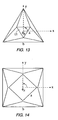
- Figure 14 shows a plan view of a 4-4 parallel platform as a square anti-prism.
- a 3-3 parallel platform is an octahedron; a 5-5 parallel platform is a pentagonal anti-prism.
- the calculations of the quality index for a 4-4 parallel platform of Figure 14 are similar to those for the 3-3 platform of Figure 13. However, because the 4-4 line coordinates yield a 6x8 matrix, the determinate is not so easily calculated. To square the calculation, the index includes the product of the matrix and its transpose, as shown in equation (4). EQUATION (4)
- a 6-6 parallel platform (hexagonal anti-prism) is the basis for this deployable antenna architecture of the present invention.
- similar quality index values are developed, so as to define the stability of the 6-6 structure once it is in an equilibrium position.
- the Cauchy-Binet theorem is used to determine the index.
- Figure 15 shows a perspective view of a 6-6 parallel platform in a rotational position offset from the tensegrity position shown in Figure 12, referenced above.
- a 6-6 parallel platform has an upper hexagonal planar platform 141 formed of a plurality of tensioned ties 151 arrayed in parallel with a lower hexagonal planar base 142 formed of a plurality of tensioned ties 152.
- the vertices of the two hexagonal arrays are interconnected by a set of twelve generally vertical legs S half of which are comprise struts and half of which comprise tensioned ties.
- This structure provides six degrees of freedom, with the struts being controllably adjustable to establish parameters of an antenna surface subsystem supported by the 6-6 parallel platform, as will be described.
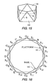
- FIG. 16 A plan view of the 6-6 parallel platform structure of Figures 12 and 15 is shown in Figure 16.
- the coordinates of the vertices of the ties 151 of the platform 141 are A through F, while the coordinates of the vertices of ties 152 of the base 142 are denoted G A through G F .
- the first truss segment is denoted as S 1 (heavy lines), and extends between (base) vertex G A and (platform) vertex A. Proceeding around the 6-6 parallel platform structure, the last or twelfth truss segment is S 12 , extending between bases vertex F and platform vertex G A . All of the base coordinates are fixed (no possible motions), and all z or vertical axis values are equal to zero (0).
- the values of the base coordinates are set forth in Appendix 1, while line coordinates for the platform vertices at the neutral position (the twelve legs are all the same nominal length) are set forth in Appendix 2.
- a set of Plucker matrices may be defined as set forth in Appendix 3, to provide a set of (L, M, N, P, Q, R) Plucker coordinates for the twelve legs S 1 -S 12 .
- the normalized Plucker coordinates were determined by dividing the calculated value by the nominal lengths of the legs for the neutral position, as defined by equation (7).
- the J matrix comprised of the Plucker coordinates for the twelve legs, is a 12x6 array, set forth in Appendix 4.
- the transpose J T is set forth in Appendix 5.
- Equation (8) shows the calculation of the optimization value for the 6-6 J matrix (non-symmetric) is similar to that for the 4-4 platform solution which, like the 3-3 platform is known.
- Equation (14) the product of the J and J T matrices is calculated, as in equation (9).
- the combined matrices are simplified in equation (14) as: EQUATION (14)
- the present invention manipulates the struts of the 6-6 parallel platform structure using a screw-motion based drive, in order to controllably adjust the twist and pitch of the tensegrity structure, and thereby deploy and tune one or more characteristics of the energy-focusing surface it supports.
- the lower base 143 remains fixed, while the upper platform 141, to which the perimeter of the antenna surface is attached, is rotated about thereby and axially displaced along the screw's z axis as it effectively moves along a screw of variable pitch h.
- Appendix 6 contains relationships associated with this screw motion of the geometry of an octahedron, as described by J.
- the radius from the center of the 6-6 parallel platform structure to the platform coordinates is equal to the length of the platform side.
- the Plucker line coordinates are calculated using Grassman's principle by counting the 2x2 determinants of each of the 2x4 arrays set forth in Appendix 7.
- the Plucker coordinates are defined by the determinants of Appendix 8. From these values, the transpose of Jacobian matrix of Appendix 9 may be obtained.
- the Plucker coordinates define the length of the legs for this structure, as set forth in Appendix 10.
- adjacent legs are of equal length, and may be defined by equation (18) as: EQUATION (18)
- Figure 17 shows the rotation of the 6-6 parallel platform structure of Figures 15 and 16 through tensegrity.
- every other (even numbered) leg of the structure is a strut, while the remaining (odd numbered) legs therebetween have been replaced by tensioned ties.
- tensegrity occurs when all struts (S 2 , S 4 , S 6 , S 8 , S 10 , and S 12 ) are in compression, and all ties (S 1 , S 3 , S 5 , S 7 , S 9 , and S 11 ) are in tension.
- the struts (S 2 , S 4 , S 6 , S 8 , S 10 , and S 12 ) cannot be in tension because they interface only with tensile members (ties 151 that form the six sides of platform 141, the ties 152 that form the six sides of platform 142, and ties S 1 , S 3 , S 5 , S 7 , S 9 , and S 11 ).
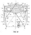
- Figure 18 diagrammatically illustrates a parabolically shaped reflective mesh 170 that is supported by an arrangement of cords 171 and ties 172
- Figure 19 is a side sectional diagram of the structure of Figure 18, showing in broken lines the manner in which the parabolic shape of the reflective mesh 170 of the antenna readily geometrically adjoins a stable hyperboloid shape 175 realized by the compression struts and ties of the tensegrity structure.
- the antenna mesh 170 may be readily attached to the 6-6 parallel platform structure by means of fasteners commonly employed for space-deployed structures, at a plurality of points along its circular perimeter to the six platform vertices A-F.
- Each of the compression struts S 2 , S 4 , S 6 , S 8 , S 10 , and S 12 is controllably, rotationally manipulated, as by means of electro-mechanically driven linkages coupled thereto from a strut manipulator subsystem 154, so as to perform a screw path motion about a central longitudinal axis 150.
- this screw path motion serves to change both the separation or spacing z between the upper tie platform 141 and the lower tie base 142, as well as their mutual differential rotation about the axis 150, and thereby deploys the structure and attached antenna mesh 170 from their stowed condition into their intended 'tensegrity state' geometry.
- defocus is addressed by analysis of any 'cupping' of structural components, given the assumption that there are constant errors inherent in the antenna subsystem once it is deployed. For a given reflector surface an associated tolerance is established for a characteristic design (e.g., an L-band commercial antenna which require a surface accuracy in the microns).
- the initial positions of the struts may be modified as necessary to control the geometry of the antenna reflector perimeter.
- a particularly beneficial feature of the invention is the use of screw-based differential axial positioning of the platform relative to the base, which enables the antenna reflector surface to direct the RF energy toward respectively different foci. This enables different receiver feeds to be located in the vicinity of a nominal focal point, allowing different beams at different frequencies to be directed to these receivers.
- Stowage within the envelope or shroud of the launch vehicle must also be considered along with the above issues of antenna performance.
- antenna subsystems are designed with one extra fold along the length of the struts. Nominally this means that a 20-meter diameter antenna would have a maximum stowed package density of approximately 5-meter height and several meters in diameter.
- the use of a minimum number of rigid elements here, six struts, which may be configured as telescoping components) allows present day packaging schemes to maximize stowage density for a fixed spacecraft region (area or volume).
- the struts and ties may be deployed by means of a reel 181 mounted to the distal ends of a strut 180.
- the strut is configured as a hollow tube that is sized to receive and stow (three) ties (corresponding to an adjacent (odd) leg S oi and two connected ties 151 of the platform 141) that deploy from the within the strut proper along the arrow paths of Figure 21.
- This simple, yet durable approach solves the problem of variable length ties for special antenna designs, such as those with multiple feed centers (focal points on the parabolic antenna surface).
- the base of the strut 180 is provided with a revolute joint 182 to ensure that there are only translational constraints.
- the present invention is able to compactly stow, deploy and support an energy focusing surface, such as a furlable conductive material for a radio wave antenna.
- an energy focusing surface such as a furlable conductive material for a radio wave antenna.
- the pitch and the shape of the supported energy-focusing surface may be controllably adjustable, so as to facilitate compensating corrections for defocus, mispointing, and surface roughness.
- Screw motion-driven tensegrity antenna support architecture to deploy for adjustable control of an energy-focusing surface, such as an RF wave-reflecting conductive mesh.
- an energy-focusing surface such as an RF wave-reflecting conductive mesh.
- an energy-focusing surface such as an RF wave-reflecting conductive mesh.
- Vertices of the hexagonal tie base and the hexagonal upper tie platform are interconnected by pairs of legs, each including a compression strut and a tension tie.
- the stability of the structure requires that the sum of the tie tension forces matches the sum of the compression forces in the struts.
- a screw motion-based drive system is coupled to the struts to define relative mutual rotation and pitch between the upper platform and lower base.
- the RF reflective surface is supported by an arrangement of cords and ties attached at points along its circular perimeter to the six platform vertices of the parallel platform structure.
Landscapes
- Engineering & Computer Science (AREA)
- Physics & Mathematics (AREA)
- Thermal Sciences (AREA)
- Life Sciences & Earth Sciences (AREA)
- Sustainable Development (AREA)
- Sustainable Energy (AREA)
- Electromagnetism (AREA)
- Chemical & Material Sciences (AREA)
- Combustion & Propulsion (AREA)
- Mechanical Engineering (AREA)
- General Engineering & Computer Science (AREA)
- Aerials With Secondary Devices (AREA)
- Details Of Aerials (AREA)
Abstract
Description
- The present invention relates to energy focusing surfaces, such as radio wave antennas, solar concentrators, and the like and is particularly directed to a screw motion-driven tensegrity support architecture, that is configured to stably deploy and adjustably control characteristics of the energy-focusing surface.
- The field of deployable structures, such as space-deployed platforms, has matured significantly in the past decade. What once was a difficult art to master has been developed into a number of practical applications by commercial enterprises. The significance of this maturity has been the reliable deployment of various spacecraft-supported antenna systems, similar to that employed by the NASA tracking data and relay satellite (TDRS). In recent years, the development of parabolic, mesh-surface, reflector geometries has been accompanied by improvements in phased arrays (flat panel structures with electronically steered beams), both of which are critical to commercial and defense space programs. As commercial spacecraft production has exceeded military/ civil applications, there is currently a demand for structural systems with proven reliability and performance, and the ever present reduced cost. As described in the text by Larson and Wertz, entitled "Space Mission Analysis and Design," Microcosm, Inc., ISBM: 1881883019; November 1992; 2nd Edition, a spacecraft system's requirements may be defined through a process of identifying broad objectives, reasonably achievable goals, and cost constraints. Although space missions vary greatly, and the requirements, goals, and costs associated with each task also vary greatly, one constraint is always present: "space is expensive."
- The mission objective for a large, deployable space antenna is to provide reliable radio frequency (RF) energy reflection to an electronic collector (feed) located at the focus of the parabolic surface. The current state of deployable parabolic space antenna design is principally based on what may be termed a segmented construction approach which, as shown in Figures 1-4, is configured much like an umbrella. In this type of design, a plurality of radial ribs or
segments 1 are connected to acentral hub 3, that supports anantenna feed 5. A mechanical advantaged linear actuator (not shown) is used to drive thesegments 1 from their stowed or unfurled condition, shown in the diagrammatic side and end views of Figures 1 and 2, into a locked, over-driven, position, so as to deploy asurface 7, as shown in the diagrammatic side and end views of Figures 3 and 4. A shortcoming of a single fold design of this type of antenna is the fact that the height of the stowed package is over one half of the deployed diameter. Other proposals include the use of hoop tensioners and mechanical memory surface materials. - To meet the above-stated objective, an analysis of mathematics and electrical engineering yields three fundamental parameters of the antenna: 1-defocus, 2-mispointing, and 3-surface roughness. As diagrammatically illustrated in Figure 5, for a receiving antenna, defocus is defined as the error the surface of a
reflector 10 that causes the receivedenergy 12 to paint or be projected upon anarea 14, rather than converge onto a focal point (where an antenna feed is placed). As shown in Figure 6, mispointing corresponds to the misplacement of the convergedenergy 12 to aspatial position 16 other than the designedfocal point 18. The third characteristic - surface roughness (or the approximation of a prescribed (e.g., parabolic) surface geometry), defines the reflector's ability to reflect and collect a given band of RF energy. Higher band reflectors require a more accurate surface that better approximates the theoretical parabola. Conversely, for a transmitting antenna, defocus produces divergent (rather than parallel) waves of energy from the reflector surface, while mispointing directs these waves in the wrong direction. - In recent years, numerous organizations have solicited for new approaches to deployable antenna structures. The Air Force Research Laboratories (AFRL) of the United States are interested in solutions to aid with their Space Based Laser and Radar programs, and have requested new solutions to building precision deployable structures to support the optical and radar payloads. These requests are based upon the premise that the stowed density for deployable antennas can be significantly increased, while maintaining the reliability that the space community has enjoyed in the past. A failure of these structures is unacceptable. If the stowed volume can be reduced (therefore an increase in density for a given weight), launch services can be applied more efficiently.
- The implementation of multiple vehicle launch platforms (e.g., the Iridium satellite built by Motorola) has presented a new case where the launch efficiency is a function of the stowed spacecraft package, and not the weight of the electronic bus. For extremely high frequency (EHF) systems (greater than 20 GHz) in low earth orbit (LEO), the antenna aperture needs to be only a few meters in diameter. However, for an L-band, geosynchronous orbit satellite (such AceS built by Lockheed Martin, United States), the antenna aperture diameter is fifty feet. Less weight and payload drag must be achieved to ensure a more efficient assent into a geosynchronous orbit.
- A relatively comprehensive study of the technology needs for future space systems to be published in the last decade was released by the International Technology Research Institute in a WTEC Panel Report entitled: "Global Satellite Communications Technology and Systems, Executive Summary," November 11,1998. This NSF/ NASA sponsored research commissioned a panel of U.S. satellite engineers and scientists to study international satellite R&D projects to evaluate the long-term presence of the United States in this industry. A prior study was undertaken in 1992 to establish that there was significant activity in Europe and Asia that correspond to that of the U.S., and benchmarked this R&D to U.S. capability. The later study added market, regulatory, and policy issues in addition to the technology developments. The conclusion was that while the U.S. holds a lead in the space marketplace, there are ongoing gains by other continents. This is evident in space launch, where Ariane Space has nearly achieved the capabilities of Boeing's (Delta) rocket services.
- Once significant aspect of this study is that U.S. manufacturers are meeting their goals for short-term research (achieving program performance), but have greatly neglected the long-term goals, which has traditionally been funded by the government. A top candidate technologies include structural elements, materials and structures for electronic devices, and large deployable antennas (having diameters in excess of twenty-five meters). While there have been fourteen meter subsystems developed to meet geosynchronous system requirements during the 1990s, the large deployable requirement has yet to be addressed or developed.
- Tetrobots have been developed in the last few years as a new approach to modular design. The tetrobot approach, which is described in the text by G. Hamlin et al, entitled: "TETROBOT, A Modular Approach to Reconfigurable Parallel Robotics," Kluwer Academic Publishers, 1998 (ISBN: 0-7923-8025-8) utilizes a system of hardware components, algorithms, and software to build various robotic structures to meet multiple design needs. These structures are Platonic Solids (tetrahedral and octahedral modules), with all the connections made with truss members. As described in the text by P. Tidwell et al, entitled: "Kinematic Analysis of Generalized Adaptive Trusses," First Joint U.S./Japan Conference on Adaptive Structures, November 13-15, 1990, Technomic Publishing Co., pp. 772-791, adaptive trusses have been applied to the field of deployable structures; providing the greatest stiffness and strength for a given weight of any articulated structure or mechanism. Using the tetrahedron geometry (6-struts and 4-vertices) as its basis, the Tidwell et al text proposes a series of octahedral cells (12-struts and 6-vertices) to build an adaptive structure. An article by B. Wada et al, entitled: "Using Adaptive Structures to Enable Future Missions by Relaxing Ground Test Requirements, Journal of Spacecraft, Vol. 28, No. 6, Nov.-Dec. 1991, pp. 663-669 concludes that from well defined forward analyses (position, velocity and acceleration), this adaptive truss would be useful for deployed structures to remove position or motion errors caused by manufacturing, temperature change, stress, or external force.
- The most complex issue in developing a reliable deployable structure design is the packaging of a light weight subsystem in as small a volume as possible, while ensuring that the deployed structure meets system requirements and mission performance. An article by D. Warnaar, entitled: Evaluation Criteria for Conceptual of Deployable-Foldable Truss Structures," ASME Design Engineering: Mechanical Design and Synthesis, Vol. 46, pp. 167-173, 1992, in describing criteria developed for deployable-foldable truss structures, addresses the issues of conceptual design, storage space, structural mass, structural integrity, and deployment. This article simplifies the concepts related to a stowed two-dimensional area deploying to a three-dimensional volume. A tutorial on deployable-foldable truss structures is presented in: "Conceptual Design of Deployable-Foldable Truss Structures Using Graph Theory-Part 1: Graph Generation," by D. Warnaar et al, ASME 1990 Mechanisms Conference, pp.107-113, September 1990, and "Conceptual Design of Deployable-Foldable Truss Structures Using Graph Theory-Part 2: Generation of Deployable Truss Module Design Concepts, by D. Warnaar et al, ASME, 1990 Mechanisms Conference, pp.115-125, September 1990. This series of algorithms presents a mathematical representation for the folded (three-dimensional volume in a two-dimensional area) truss, and aids in determining the various combinations for a folded truss design.
- NASA's Langley Research Center has extensive experience in developing truss structures for space. One application, a 14-meter diameter, three-ring optical truss, was designed for space observation missions. An article by K. Wu et al, entitled: "Multicriterion Preliminary Design of a Tetrahedral Truss Platform," Journal of Spacecraft and Rockets, Vol. 33, No. 3, May-June 1996, pp. 410-415, details a design study that was performed using the Taguchi methods to define key parameters for a Pareto-optimal design: maximum structural frequency, minimum mass, and the maximum frequency to mass ratio. In the study, tetrahedral cells were used for the structure between two precision surfaces. 31 analyses were performed on 19,683 possible designs with an average frequency-to-mass ratio between 0.11 and 0.13 Hz/kg. This results in an impressive 22 to 26 Hz for a 200-kg structure.
- The field of deployable space structures has proven to be both technically challenging and financially lucrative during the last few decades. Such applications as large parabolic antennas require extensive experience and tooling to develop, but is a key component to the growing personal communications market. Patents relating to deployable space structures have typically focused on the deployment of general truss network designs, rather than specific antenna designs. Some of these patents address new approaches that have not been seen in publication.
- For example, the specifications of U.S. Patents No. 4,030,102, and No. 4,825,225 disclose the application of strut and tie construction to deployable antennas. However, the majority of such patents address trusses and the issues associated with their deployment and minimal stowage volume. For example, the specification of U.S. Patent No. 4,539,786 discloses a design for a three-dimensional rectangular volume based on an octahedron. Deployment uses a series of ties within the truss network, and details of the joints and hinges are described. When networked with other octahedral subsets, a compact stow package could be expended into a rigid three-dimensional framework.
- Other patent specifications described continued work in expandable networks to meet the needs of International Space Station. For example, the specification of U.S. Patent No. 4,655,022, employs beams and triangular plates to form tetrahedral units that provide a linear truss.
- In the article by Duffy I. et al, entitled "Review of a family of self-deploying tensegrity structures with elastic ties", Shock and Vibration Digest, Vol. 32, No. 2,1 - March 1, 2000, pp. 100-106, a tensegrity structure is described which can be compactly stowed and deployed to form an energy focusing surface, such as radio wave antenna. Through the use of a screw-motion based deployment and positioning drive of the scrubs of the tensegrity structure, the pitch and thereby the shape of the supported energy-focusing surface may be controllably adjusted. A 6-6 parallel platform structure comprises an upper hexagonal platform and a lower hexagonal base, the perimeter geometry of which is defined by a plurality of interconnected tensioned ties. Vertices of the hexagonal tie base and the hexagonal upper tie platform are interconnected by a set of 12 legs, with a pair of legs extending from each vertex of a respective hexagonal platform/base tie set to adjacent vertices of the opposite hexagonal base/platform tie set. Each leg pair includes a compression member or a strut and a tension member or tie respectively. A screw-motion based drive is coupled to the compression members to rotate the upper platform relative to the base and to deploy the antenna and screw-drive the support structure about a central longitudinal axis to its tensegrity state.
- The present invention includes a method of deploying an antenna support architecture by importing a screw-based differential axial positioning motion to a platform structure relative to a base structure of said architecture to unfurl a furlable radio wave-reflective material into an antenna when the architecture is placed in a tensegrity condition while causing said furlable radio wave-reflective material to deploy to a prescribed antenna surface geometry, in which said support architecture comprises a first tension member-configured polygon (154) and a second tension member-configured polygon (152), with each vertex of said first polygon being respectively connected by a tension member and a compression member to adjacent vertices of said second polygon, and wherein each vertex of said second polygon being respectively connected by a tension member and a compression member to adjacent vertices of said first polygon, so that compression members alternate with tension members between said first and second polygons, with opposite ends of each compression member connecting only to tension members, placing said structure in said tensegrity condition to cause the sum of the tension forces in said tension members to match the sum of compression forces in said compression members, and in which preferably each of said first and second polygons comprises a hexagon, characterized by forming said antenna surface geometry in a parabolically shaped reflective mesh (170) that is supported by an arrangement of cords (171) and ties (172) and providing vernier adjustment of the parabolic shape through The supporting compression members and/or the tension members.
- The invention also includes an antenna comprising a structurethat is adapted to be configured into a tensegrity condition by importing a screw-based differential axial positioning motion and causing a furlable radio wave-reflective material to deploy to an antenna surface geometry, in which said structure includes a first tension member-configured polygon and a second tension member-configured polygon spaced in parallel relation to said first polygon, vertices of said first polygon being coupled by tension and compression members to vertices of said second polygon, and a structure manipulator operative to impart said screw-motion to said compression members to effect axial displacement with mutual relative rotation between said first and second tension member-configured polygons and thereby place said structure in said tensegrity condition, each vertex of said first polygon being respectively connected by one said tension members and one said compression members to adjacent vertices of said second polygon, and each vertex of said second polygon is respectively connected by one said tension members and one said compression member to adjacent vertices of said first polygon, so that compression members alternate with tension members between said first and second polygons, with opposite ends of each compression member connecting only to tension member, characterized in that
after deployment said antenna surface geometry forms a parabolically shaped reflective mesh that is supported by forming said antenna surface geometry in a parabolically shaped reflective mesh that is supported by an arrangement of cords and ties the compression members and/or the tension members, when said structure manipulator places said antenna structure in said tensegrity conditon. - It is advantageous to form a highly stable structure, known as a tensegrity structure, to compactly stow, deploy and support an energy focusing surface, such as radio wave antenna, solar concentrator, and the like. In addition, through the use of a screw-motion based deployment and positioning drive of the struts of the tensegrity structure, the pitch and thereby the shape of the supported energy-focusing surface may be controllably adjusted, to facilitate compensating corrections for antenna defocus, mispointing, and surface roughness.
- A 6-6 platform structure for deploying and supporting an energy directing surface, such as a parabolic RF electromagnetic antenna, is suitably configured such that the lowest energy state for the platform structure is in a screw-rotated 6-6 tensegrity position. The 6-6 parallel platform structure comprises an upper hexagonal platform and a lower hexagonal base, the perimeter geometry of each of which is defined by a plurality of interconnected tensioned ties. Vertices of the hexagonal tie base and the hexagonal upper tie platform are interconnected by a set of twelve legs, with a pair of legs extending from each vertex of a respective hexagonal platform/base tie set to adjacent vertices of the opposite hexagonal base/platform tie set. Each leg pair includes a compression member or strut and a tension member or tie. Namely, the twelve legs include six compression struts and an alternating set of six tensioned ties, so that opposite ends of each compression strut connect only to tensioned ties.
- The stability of this 6-6 structure requires that the sum of the tie tension forces matches the sum of the compression forces in the struts. This structure provides six degrees of freedom, with the struts being controllably adjustable to establish parameters of an antenna surface subsystem that is supported by the 6-6 parallel platform. Since the geometry of each of the base and the platform is a hexagon, the radius from the center of the 6-6 parallel platform structure to the platform coordinates is equal to the length of the platform/base side. Using the base and platform geometries, Plucker line coordinates are calculated to define the length of the legs.
- In order to control deployment from a stowed condition and the geometric parameters of the deployed structure, a screw motion-based drive system is coupled to the struts to realize and providing vernier adjustment of the parabolic shape through a relative z/ Θz motion or pitch p, The pitch, namely the separation between the upper platform and lower base, is defined as the ratio of linear z change to rotation about the z axis, which typically corresponds to the boresight axis of the antenna surface being deployed. A (parabolically) shaped reflective surface, such as a conductive mesh may be supported by an arrangement of cords and ties attached at a plurality of points along its circular perimeter to the six platform vertices of the 6-6 parallel platform structure, so that the operation of the struts will fully deploy the antenna into its intended geometry as the support structure is screw-driven from its stowed configuration in its tensegrity state.
- Key parameters associated with successful operation of deployable antennas are defocus, mispointing, and surface roughness. Since the tensegrity structure of the present invention allows control of the component kinematics of the parallel platform structure, in particular the positioning of the six struts,' tuning' adjustments to the positions of the struts may be made for any or all of these parameters to comply with a prescribed antenna performance specification. Defocus may be addressed by analysis of any 'cupping' of structural components, given the assumption that there are constant errors inherent in the antenna subsystem once deployed. For a given reflector surface a tolerance is established for an associated performance specification. The initial positions of the struts may be modified as necessary to control the geometry of the antenna reflector perimeter.
- Mispointing deals with improper geometry of the surface causing the energy to be directed to the wrong (theoretical) focal point, although the focal point is actually a focal plane, due to energy management issues with RF transmitter/receivers. The ability to control the positions of the struts provides for surface geometry adjustment so as to direct the RF energy within the boundaries of this plane. The use of screw-based differential axial positioning of the platform relative to the base, which enables the antenna reflector surface to direct the RF energy toward respectively different foci. This enables different receiver feeds to be located in the vicinity of a nominal focal point, allowing different beams at different frequencies to be directed to these receivers.
- Surface accuracy depends on properties of the reflective surface (e.g., reflective mesh), such as but not limited to non-linear stiffness, and reflective mesh surface material. Positioning and control of the reflector material through vernier adjustment of the strut support structure and/or the tensioning ties may be employed to provide compensation for properties of the surface material. The use of a minimum number of rigid elements (six compression struts) of the 6-6 tensegrity parallel platform structure of the invention also facilitates maximizing stowage density for a fixed spacecraft area or volume.
- The present invention will now be described, by way of example, with reference to the accompanying drawings, in which:
- Figures 1 and 2 are respective diagrammatic side and end views of the stowed condition of a conventional segmented radial rib-based space-deployable parabolic antenna;
- Figures 3 and 4 are respective diagrammatic side and end views of the deployed condition of the antenna of Figures 1 and 2;
- Figure 5 diagrammatically illustrates the defocus of a reflector surface;
- Figure 6 diagrammatically illustrates mispointing of a reflector surface;
- Figure 7 shows a simple tetrahedron as a four-vertex, six-edged member structure;
- Figure 8 shows an interior tripod system of four struts from which a tensegrity structure of the tetrahedron of Figure 7 may be realized;
- Figure 9 shows a simple octahedron;
- Figure 10 shows the octahedron of Figure 9 rotated about its center, producing a 3-3 platform structure;
- Figure 11 shows the 3-3 octahedron of Figure 10 with alternate ones of the six support struts thereof replaced by ties;
- Figure 12 is a diagrammatic perspective view of a tensegrity position of a hexagonal platform formed of a plurality of tensioned ties relative to a hexagonal base formed of a plurality of ties;
- Figure 13 diagrammatically illustrates a plan view of a 3-3 parallel platform;
- Figure 14 shows a plan view of a 4-4 parallel platform as a square anti-prism;
- Figure 15 shows a perspective view of a 6-6 parallel platform in a position rotationally offset from the tensegrity position of Figure 12;
- Figure 16 is a plan view of the 6-6 parallel platform structure of Figures 12 and 15;
- Figure 17 shows successive conditions of rotation of the 6-6 parallel platform structure of Figures 15 and 16 through tensegrity;
- Figure 18 diagrammatically illustrates a parabolically shaped reflective mesh attached at a plurality of points along its circular perimeter to the six platform vertices of a 6-6 parallel platform structure;
- Figure 19 is a side sectional broken line diagram of the structure of Figure 18; and
- Figures 20 and 21 diagrammatically illustrate struts and ties deployed by a reel mounted to distal ends of a strut.
- The architecture of the antenna support of the present invention is a 'tensegrity' structure, which is not only highly stable, but enjoys a substantial increase in stowed package density for space deployed antenna applications. In order to facilitate an appreciation of the use of a tensegrity-based support arrangement for deploying and controlling the characteristics of an energy focusing surface, such as but not limited to a parabolic antenna.
- The term 'tensegrity' is a kinematic approach to support structures derived from the two words 'tensile' and 'integrity'. It is described in an article by R. Connelly et al, entitled: "Mathematics and Tensegrity," American Scientist, Vol. 86, March-April 1998, pp. 142-151. Tensegrity was originally developed for architectural sculptures by K. Snelson in 1948. The tensegrity structure itself is described, for example, in the specification of U.S. Patent No. 3,063,52. A principal advantage of this type of design is that there is a minimum of compression elements (or struts); the stability of the tensegrity system is created through tension members (ties).
- A simplification of Snelson's work is presented in the text by A. Pugh, entitled: "An Introduction to Tensegrity," University of California Press, Berkeley, CA., 1976 (ISBN: 0-520-02996-8), beginning with a basic description of the attractions and forces in nature that govern everyday life, to applications in history of tensile and compressive members in buildings and ships, in order to achieve a balance between these forces to achieve the necessary structures for commerce and living. The introduction of Platonic solids presents the simplicity and art of tensile and compressive structures. The text by P. Pearce, entitled: "Structure in Nature is a Strategy for Design," MIT Press, Cambridge, MA., 1990 (ISBN:0-262-66045-8) describes the nature of structures and the discovery of the Platonic Solids. Plato was able to determine the nature of structures, and the structure of nature (a duality), by observing naturally occurring systems such as spider webs. Building on this work, Pearce was able to document more natural phenomenon (soap bubbles, Dragonfly wings, and cracked mud) to establish energy minimization during state change. The assumption here is that nature uses the most energy-efficient method. From these assumptions and an understanding of stress and strain in structural members (columns and beams), he was able to present a unique solution for simple, durable, high strength structures. From these conclusions, he proposed a family of residential, commercial, and industrial structures that are both aesthetically pleasing and functional.
- Figure 7 shows a simple tetrahedron as a four-vertex, six-edged member structure, while Figure 8 shows an interior (tripod) system of four struts 81-84, from which a tensegrity structure of the tetrahedron of Figure 7 may be realized by connecting the four vertices of the struts with
tensioned ties 85. Figure 9 shows a simple octahedron (having 6-vertices, 12-edges, and 8-faces) - while Figure 10 shows the octahedron of Figure 9 rotated about its center, producing a 3-3 platform-like structure having a pair of upper and lower three-sided platforms - A regular polygon-based platform structure for deploying and supporting an energy directing surface, such as a parabolic radio wave antenna, is configured such that the lowest energy state for the platform structure is in a tensegrity position. For purposes of providing a non-limiting illustrative example, the present invention will be described for the case of a regular six-polygon or hexagon for each of the platform and base of the tensegrity structure, corresponding to a '6-6' parallel platform architecture. It should be observed, however, that the invention is not limited to use with a polygon of a specific number of sides. In accordance with fundamental geometry principles, as the number of sides of the polygon is increased, the perimeter of the polygon tends acquire a more circular configuration. In terms of a practical implementation, a 6-6 structure provides a reasonable number of compression support members and connection points for a furlable reflective medium of which the antenna reflector surface is formed.
- Attention is now directed to Figure 12, which is a diagrammatic perspective view of the tensegrity position of a 6-6 structure for deploying a
hexagonal platform 111 comprised of a plurality of tensioned ties, relative to ahexagonal base 112 also formed of a plurality of tensioned ties. In Figure 12, broken lines represent (tensioned) ties and solid lines represent (compression) struts. The stability of this structure requires that the sum of the tie forces matches the sum of the compression forces in the struts that interconnect vertices of theplatform 111 with the vertices of the base 113. - An understanding of the 6-6 tensegrity platform structure of the invention may be facilitate by initially examining the geometric properties of a 3-3 parallel platform diagrammatically illustrated in the plan view of Figure 13, and described for example, in an article by J. Lee et al, entitled: "A Practical Quality Index based on the Octahedral Manipulator," International Journal of Robotics Research, October 1998, pp. 1081-1090. The calculations for the quality index lambda for the 3-3 platform line coordinates is defined by a 6-6 matrix. The side length of the platform is'a', the base is'b', and the height of the (three-sided)
platform 121 above the (three-sided)base 121 is 'h'. The determinate det J| for this 6-6 matrix (dividing by the nominal leg length to normalize the line coordinates) is readily calculated, as set forth in equation (1):
EQUATION (1) - By manipulating equation (1), differentiating the denominator with respect to h, and equating to zero (to get minimum/maximum values), a maximum h value is derived, as shown by equation (2):
EQUATION (2) - By substituting equation (2) into the original determinate, the maximum value | det J|m is obtained as set forth in equation (3):
EQUATION (3) - A new expression for the maximum determinate is formed by substituting b=τa. Differentiating with respect to τ yields the maximum ratio of b/a and h/a: τ=b/a=2; h/a=1. These values are similar to those derived for the 6-6 platform, to be described below.
- Figure 14 shows a plan view of a 4-4 parallel platform as a square anti-prism. (As described above, a 3-3 parallel platform is an octahedron; a 5-5 parallel platform is a pentagonal anti-prism.) The calculations of the quality index for a 4-4 parallel platform of Figure 14 are similar to those for the 3-3 platform of Figure 13. However, because the 4-4 line coordinates yield a 6x8 matrix, the determinate is not so easily calculated. To square the calculation, the index includes the product of the matrix and its transpose, as shown in equation (4).
EQUATION (4) - This method is derived from the Cauchy-Binet theorem, where detJ.JT = Δ1 2+ Δ2 2 + ... + Δnm 2. For any 6xn matrix this method applies. As with the 3-3 platform of Figure 13, the determinate may be calculated as shown in equation (5):
EQUATION (5) - Differentiating the denominator with respect to h yields the maximum value hm, as set forth in equation (6).
EQUATION (6) - Using the τ method described above develops the ratios
τ=b/a-2½;h/a-2=y-½. - As described briefly above, a 6-6 parallel platform (hexagonal anti-prism) is the basis for this deployable antenna architecture of the present invention. Using the previously derived mathematics, similar quality index values are developed, so as to define the stability of the 6-6 structure once it is in an equilibrium position. As with the 4-4 platform of Figure 14, the Cauchy-Binet theorem is used to determine the index. Once the mathematics is defined, details of the implementation of the 6-6 antenna will be described.
- Figure 15 shows a perspective view of a 6-6 parallel platform in a rotational position offset from the tensegrity position shown in Figure 12, referenced above. As shown in Figure 15, a 6-6 parallel platform has an upper hexagonal
planar platform 141 formed of a plurality oftensioned ties 151 arrayed in parallel with a lower hexagonalplanar base 142 formed of a plurality oftensioned ties 152. The vertices of the two hexagonal arrays are interconnected by a set of twelve generally vertical legs S half of which are comprise struts and half of which comprise tensioned ties. This structure provides six degrees of freedom, with the struts being controllably adjustable to establish parameters of an antenna surface subsystem supported by the 6-6 parallel platform, as will be described. - A plan view of the 6-6 parallel platform structure of Figures 12 and 15 is shown in Figure 16. The coordinates of the vertices of the
ties 151 of theplatform 141 are A through F, while the coordinates of the vertices ofties 152 of the base 142 are denoted GA through GF. The first truss segment is denoted as S1 (heavy lines), and extends between (base) vertex GA and (platform) vertex A. Proceeding around the 6-6 parallel platform structure, the last or twelfth truss segment is S12, extending between bases vertex F and platform vertex GA. All of the base coordinates are fixed (no possible motions), and all z or vertical axis values are equal to zero (0). The values of the base coordinates are set forth inAppendix 1, while line coordinates for the platform vertices at the neutral position (the twelve legs are all the same nominal length) are set forth in Appendix 2. - From the above-referenced Lee et al article, and an article by B. Knight, entitled: "An Analysis of Special Redundant Motions for a Square Platform," CIMAR Paper, June 1998, a set of Plucker matrices may be defined as set forth in
Appendix 3, to provide a set of (L, M, N, P, Q, R) Plucker coordinates for the twelve legs S1-S12. The normalized Plucker coordinates were determined by dividing the calculated value by the nominal lengths of the legs for the neutral position, as defined by equation (7).
EQUATION (7) - The J matrix, comprised of the Plucker coordinates for the twelve legs, is a 12x6 array, set forth in Appendix 4. The transpose JT is set forth in
Appendix 5. - Equation (8) shows the calculation of the optimization value for the 6-6 J matrix (non-symmetric) is similar to that for the 4-4 platform solution which, like the 3-3 platform is known.
EQUATION (8) - For this example, the product of the J and JT matrices is calculated, as in equation (9).
EQUATION (9)
As shown in equation (10), h is expressible as a function of a and b as:
EQUATION (10)
Substituting equation (10) into the above yields equations (11) and (12) as:
EQUATION (11)
EQUATION (12)
This provides Δ as a function of a and b as:
EQUATION (13)
From equation (13) the optimized solution is calculated by substituting b = τa. The combined matrices are simplified in equation (14) as:
EQUATION (14) - Through differentiation with respect to τ, maximum and minimum values may be calculated, as shown in equation (15), yielding the solution for the most stable geometry for a 6-6 platform.
EQUATION (15)
where τ = 2/31/2 = b/a; h = a/31/2; and b = 2a/31/2. - As described previously, the present invention manipulates the struts of the 6-6 parallel platform structure using a screw-motion based drive, in order to controllably adjust the twist and pitch of the tensegrity structure, and thereby deploy and tune one or more characteristics of the energy-focusing surface it supports. During this screw-motion based manipulation of the struts S1-S12, the lower base 143 remains fixed, while the
upper platform 141, to which the perimeter of the antenna surface is attached, is rotated about thereby and axially displaced along the screw's z axis as it effectively moves along a screw of variable pitch h. Appendix 6 contains relationships associated with this screw motion of the geometry of an octahedron, as described by J. Duffy et al in "An Investigation of some Special Motions of an Octahedron Manipulator Using Screw Theory," publication in process, December 1997. Advantageously, this screw like motion is readily produced simply by imparting each strut with the same incremental increase or decrease in length. Continuity requires that the coordinates (about the circle defined) sum to zero. Namely, as shown in equations (16) and (17):

- Similar to the above-referenced texts detailing octahedron and square platform papers, the radius from the center of the 6-6 parallel platform structure to the platform coordinates is equal to the length of the platform side. Using the base and platform coordinates previously defined, the Plucker line coordinates are calculated using Grassman's principle by counting the 2x2 determinants of each of the 2x4 arrays set forth in
Appendix 7. The Plucker coordinates are defined by the determinants ofAppendix 8. From these values, the transpose of Jacobian matrix of Appendix 9 may be obtained. The Plucker coordinates define the length of the legs for this structure, as set forth inAppendix 10. - Similarly, in the 6-6 parallel platform structure, adjacent legs are of equal length, and may be defined by equation (18) as:
EQUATION (18) - Using the same principles, the screw motion of this structure is readily defined as set forth in equations (19) and (20) as:


- The values for the summation of the L, M, P, and Q coordinates are defined as set forth in Appendix 11 and are zero; the values of the N and R summations, which are also set forth in Appendix 11, are non-zero. The second pair of legs sum similarly, as set forth in equations (21) - (26).


- For the
odd leg 1°, adding the first, third, fifth, and seventh, ninth, and eleventh rows of the matrix and substituting the expressions for the coordinates yields equation (27), wherein z replaces the value for h.

- The even leg calculation yields a similar result, as shown in equation (28).

- With half the number of legs (e.g., the odd legs (S1, S3, S5, S7, S9, and S11) replaced by tensioned ties, leaves the even numbered legs as struts (S2, S4, S6, S8, S10, and S12 which have no displacement). For this condition, the left side of each of equations (27) and (28) equals zero, and are therefore reduced to functions of only rotation and displacement, as shown in equation (29).

- The pitch p is defined in equation (30) as the ratio of linear z change to rotation about the z axis.

- This yields the pitch equation (31)

- The integration operation shown in equations (32) and (33) yields the z calculation, and demonstrates that the odd numbered legs can be controllably manipulated to realize a relative z/Θz motion or pitch.


- Figure 17 shows the rotation of the 6-6 parallel platform structure of Figures 15 and 16 through tensegrity. For the present example, every other (even numbered) leg of the structure is a strut, while the remaining (odd numbered) legs therebetween have been replaced by tensioned ties. As pointed out above, tensegrity occurs when all struts (S2, S4, S6, S8, S10, and S12) are in compression, and all ties (S1, S3, S5, S7, S9, and S11) are in tension. The struts (S2, S4, S6, S8, S10, and S12) cannot be in tension because they interface only with tensile members (
ties 151 that form the six sides ofplatform 141, theties 152 that form the six sides ofplatform 142, and ties S1, S3, S5, S7, S9, and S11). - Figure 18 diagrammatically illustrates a parabolically shaped
reflective mesh 170 that is supported by an arrangement ofcords 171 andties 172, while Figure 19 is a side sectional diagram of the structure of Figure 18, showing in broken lines the manner in which the parabolic shape of thereflective mesh 170 of the antenna readily geometrically adjoins astable hyperboloid shape 175 realized by the compression struts and ties of the tensegrity structure. Theantenna mesh 170 may be readily attached to the 6-6 parallel platform structure by means of fasteners commonly employed for space-deployed structures, at a plurality of points along its circular perimeter to the six platform vertices A-F. - Each of the compression struts S2, S4, S6, S8, S10, and S12 is controllably, rotationally manipulated, as by means of electro-mechanically driven linkages coupled thereto from a strut manipulator subsystem 154, so as to perform a screw path motion about a central
longitudinal axis 150. As described above, this screw path motion serves to change both the separation or spacing z between theupper tie platform 141 and thelower tie base 142, as well as their mutual differential rotation about theaxis 150, and thereby deploys the structure and attachedantenna mesh 170 from their stowed condition into their intended 'tensegrity state' geometry. - As described earlier, key parameters associated with successful operation of deployable (parabolic) antennas are defocus, mispointing, and surface roughness. Since the present invention allows control of the component kinematics of the parallel platform structure, in particular the positioning of the six compression struts (S2, S4, S6, S8, S10, and S12), 'tuning' adjustments of the struts may be made for any or all of these parameters to comply with a prescribed antenna performance specification.
- The issue of defocus is addressed by analysis of any 'cupping' of structural components, given the assumption that there are constant errors inherent in the antenna subsystem once it is deployed. For a given reflector surface an associated tolerance is established for a characteristic design (e.g., an L-band commercial antenna which require a surface accuracy in the microns). The initial positions of the struts may be modified as necessary to control the geometry of the antenna reflector perimeter.
- Mispointing, which deals with the problem of a improper geometry of the sufficient parabolic surface causing the energy to be directed to the wrong focal point. In reality the theoretical focal point is actually a focal plane, due to energy management issues with RF transmitter/receivers. The ability to control the positions of the struts provides for surface geometry adjustment so as to direct the RF energy within the boundaries of this plane.
- Surface accuracy depends on properties of the reflective surface, such as but not limited to non-linear stiffness, and reflective mesh surface material. Positioning and control of the reflector material through vernier adjustment of the strut support structure and/or the tensioning ties may be employed to provide compensation for properties of the surface material. An article by Z. You, entitled: "Displacement control of prestressed structures," in Computer Methods in Applied Mechanics and Engineering, Volume 144, pp. 51-59, March 15, 1997, describes tools for calculating motions of pre-stressed nodes by actuating flexible ties.
- A particularly beneficial feature of the invention is the use of screw-based differential axial positioning of the platform relative to the base, which enables the antenna reflector surface to direct the RF energy toward respectively different foci. This enables different receiver feeds to be located in the vicinity of a nominal focal point, allowing different beams at different frequencies to be directed to these receivers.
- Stowage within the envelope or shroud of the launch vehicle must also be considered along with the above issues of antenna performance. Currently, antenna subsystems are designed with one extra fold along the length of the struts. Nominally this means that a 20-meter diameter antenna would have a maximum stowed package density of approximately 5-meter height and several meters in diameter. The use of a minimum number of rigid elements (here, six struts, which may be configured as telescoping components) allows present day packaging schemes to maximize stowage density for a fixed spacecraft region (area or volume).
- As diagrammatically illustrated in Figures 20 and 21, to facilitate compact stowage, the struts and ties may be deployed by means of a
reel 181 mounted to the distal ends of astrut 180. The strut is configured as a hollow tube that is sized to receive and stow (three) ties (corresponding to an adjacent (odd) leg Soi and twoconnected ties 151 of the platform 141) that deploy from the within the strut proper along the arrow paths of Figure 21. This simple, yet durable approach solves the problem of variable length ties for special antenna designs, such as those with multiple feed centers (focal points on the parabolic antenna surface). The base of thestrut 180 is provided with a revolute joint 182 to ensure that there are only translational constraints. - By taking advantage of the structural and stability properties of a tensegrity structure, the present invention is able to compactly stow, deploy and support an energy focusing surface, such as a furlable conductive material for a radio wave antenna. Moreover, by coupling the struts of the tensegrity structure to a screw-motion based deployment and positioning drive, the pitch and the shape of the supported energy-focusing surface may be controllably adjustable, so as to facilitate compensating corrections for defocus, mispointing, and surface roughness.
- Screw motion-driven tensegrity antenna support architecture to deploy for adjustable control of an energy-focusing surface, such as an RF wave-reflecting conductive mesh. With a 6-6 parallel platform structure an upper hexagonal platform and a lower hexagonal base, the perimeter geometry of each is defined by plural interconnected tensioned ties. Vertices of the hexagonal tie base and the hexagonal upper tie platform are interconnected by pairs of legs, each including a compression strut and a tension tie. The stability of the structure requires that the sum of the tie tension forces matches the sum of the compression forces in the struts. To control deployment from a stowed condition and the geometric parameters of the deployed RF reflecting surface, a screw motion-based drive system is coupled to the struts to define relative mutual rotation and pitch between the upper platform and lower base. The RF reflective surface is supported by an arrangement of cords and ties attached at points along its circular perimeter to the six platform vertices of the parallel platform structure.
Claims (2)
- A method of deploying an antenna support architecture by importing a screw-based differential axial positioning motion to a platform structure relative to a base structure of said architecture to unfurl a furlable radio wave-reflective material into an antenna when the architecture is placed in a tensegrity condition while causing said furlable radio wave-reflective material to deploy to a prescribed antenna surface geometry, in which said support architecture comprises a first tension member-configured polygon (154) and a second tension member-configured polygon (152), with each vertex of said first polygon being respectively connected by a tension member and a compression member to adjacent vertices of said second polygon, and wherein each vertex of said second polygon being respectively connected by a tension member and a compression member to adjacent vertices of said first polygon, so that compression members alternate with tension members between said first and second polygons, with opposite ends of each compression member connecting only to tension members, placing said structure in said tensegrity condition to cause the sum of the tension forces in said tension members to match the sum of compression forces in said compression members, and in which preferably each of said first and second polygons comprises a hexagon,
characterized by
forming said antenna surface geometry in a parabolically shaped reflective mesh (170) that is supported by an arrangement of cords (171) and ties (172) and providing vernier adjustment of the parabolic shape through the supporting compression members and/or the tension members. - An antenna comprising a structure that is adapted to be configured into a tensegrity condition by importing a screw-based differential axial positioning motion and causing a furlable radio wave-reflective material to deploy to an antenna surface geometry, in which said structure includes a first tension member-configured polygon (151) and a second tension member-configured polygon (152) spaced in parallel relation to said first polygon, vertices (A, B, C, D, E, F) of said first polygon being coupled by tension and compression members (S1, S2, S3, S4, S5, S6, S7, S8, S9, S10, S11, S12) to vertices (GA, GB, GC, GD, GE, GF) of said second polygon, and a structure manipulator operative to impart said screw-motion to said compression members (S2, S4, S6, S8, S10, S12) . to effect axial displacement with mutual relative rotation between said first and second tension member-configured polygons (151;152) and thereby place said structure in said tensegrity condition, each vertex (A, B, C, D, E, F) of said first polygon (151) being respectively connected by one said tension members (S1, S3, S5, S7, S9, S11) and one said compression members (S2, S4, S6, S8, S10, S12) to adjacent vertices (GA,GB; GB,GC; GC,GD; GD,GE; GE,GF; GF,GA) of said second polygon (152), and each vertex (GA, GB, GC, GD, GE, GF) of said second polygon (152) is respectively connected by one said tension members (S1, S3, S5, S7, S9, S11) and one said compression members (S2, S4, S6, S8, S10, S12) to adjacent vertices (A,F; B,A; C,B; D,C; E,D; F,E) of said first polygon (151), so that compression members alternate with tension members between said first and second polygons, with opposite ends of each compression member connecting only to tension member,
characterized in that
after deployment said antenna surface geometry forms a parabolically shaped reflective mesh (170) that is supported by forming said antenna surface geometry in a parabolically shaped reflective mesh (170) that is supported by an arrangement of cords (171) and ties (172) and providing vernier adjustment of the parabolic shape through the compression members and/or the tension members when said structure manipulator places said antenna structure in said tensegrity condition.
Applications Claiming Priority (3)
| Application Number | Priority Date | Filing Date | Title |
|---|---|---|---|
| US09/539,630 US6441801B1 (en) | 2000-03-30 | 2000-03-30 | Deployable antenna using screw motion-based control of tensegrity support architecture |
| US539630 | 2000-03-30 | ||
| PCT/US2001/009560 WO2001076011A2 (en) | 2000-03-30 | 2001-03-19 | Deployable antenna |
Publications (2)
| Publication Number | Publication Date |
|---|---|
| EP1269574A2 EP1269574A2 (en) | 2003-01-02 |
| EP1269574B1 true EP1269574B1 (en) | 2006-05-31 |
Family
ID=24152011
Family Applications (1)
| Application Number | Title | Priority Date | Filing Date |
|---|---|---|---|
| EP01926429A Expired - Lifetime EP1269574B1 (en) | 2000-03-30 | 2001-03-19 | Deployable antenna |
Country Status (6)
| Country | Link |
|---|---|
| US (1) | US6441801B1 (en) |
| EP (1) | EP1269574B1 (en) |
| AT (1) | ATE328373T1 (en) |
| AU (1) | AU2001252963A1 (en) |
| DE (1) | DE60120135T2 (en) |
| WO (1) | WO2001076011A2 (en) |
Families Citing this family (25)
| Publication number | Priority date | Publication date | Assignee | Title |
|---|---|---|---|---|
| US6984049B2 (en) * | 2002-11-04 | 2006-01-10 | General Dynamics Advanced Information Systems, Inc. | Hinged substrate for large-aperture, lightweight, deformable mirrors |
| US7278245B2 (en) * | 2003-07-21 | 2007-10-09 | Rouse Glenn R | Radial-hinge mechanism |
| US6970143B2 (en) * | 2004-03-16 | 2005-11-29 | Harris Corporation | Highly compact, precision lightweight deployable truss which accommodates side mounted components |
| US7138960B2 (en) * | 2004-08-27 | 2006-11-21 | United Technologies Corporation | Deployable electromagnetic concentrator |
| US20060227063A1 (en) * | 2005-04-07 | 2006-10-12 | Vanguard Composites Group, Inc. | Star-rib backing structure for a reflector system |
| JP5299291B2 (en) * | 2008-02-13 | 2013-09-25 | コニカミノルタ株式会社 | Movable tensegrity structure |
| US7710348B2 (en) * | 2008-02-25 | 2010-05-04 | Composite Technology Development, Inc. | Furlable shape-memory reflector |
| US8195118B2 (en) | 2008-07-15 | 2012-06-05 | Linear Signal, Inc. | Apparatus, system, and method for integrated phase shifting and amplitude control of phased array signals |
| US9281569B2 (en) | 2009-01-29 | 2016-03-08 | Composite Technology Development, Inc. | Deployable reflector |
| US8259033B2 (en) * | 2009-01-29 | 2012-09-04 | Composite Technology Development, Inc. | Furlable shape-memory spacecraft reflector with offset feed and a method for packaging and managing the deployment of same |
| US8872719B2 (en) | 2009-11-09 | 2014-10-28 | Linear Signal, Inc. | Apparatus, system, and method for integrated modular phased array tile configuration |
| US8698681B2 (en) | 2010-04-21 | 2014-04-15 | City University Of Hong Kong | Solar energy collection antennas |
| US8599081B2 (en) | 2010-04-21 | 2013-12-03 | City University Of Hong Kong | Solar energy collection antennas |
| US9366853B2 (en) | 2011-02-25 | 2016-06-14 | Utah State University Research Foundation | Multiple petal deployable telescope |
| WO2012116366A2 (en) * | 2011-02-25 | 2012-08-30 | Utah State University Research Foundation | Multiple petal deployable telescope |
| US8474760B2 (en) | 2011-03-16 | 2013-07-02 | Stephen Leventhal | Polygonal support structure |
| US8616328B2 (en) * | 2012-02-27 | 2013-12-31 | California Institute Of Technology | Method and apparatus for wave generation and detection using tensegrity structures |
| WO2013140201A1 (en) * | 2012-03-19 | 2013-09-26 | Agence Spatiale Europeenne | A deployable tensegrity structure, especially for space applications |
| US10811759B2 (en) | 2018-11-13 | 2020-10-20 | Eagle Technology, Llc | Mesh antenna reflector with deployable perimeter |
| US12083674B2 (en) | 2018-12-13 | 2024-09-10 | Etegent Technologies, Ltd. | Preloaded strut |
| US11139549B2 (en) | 2019-01-16 | 2021-10-05 | Eagle Technology, Llc | Compact storable extendible member reflector |
| US11942687B2 (en) | 2019-02-25 | 2024-03-26 | Eagle Technology, Llc | Deployable reflectors |
| US10797400B1 (en) | 2019-03-14 | 2020-10-06 | Eagle Technology, Llc | High compaction ratio reflector antenna with offset optics |
| AT523050B1 (en) | 2019-09-26 | 2021-05-15 | Artner Dr Gerald | antenna |
| US11870183B2 (en) | 2019-10-01 | 2024-01-09 | Honeybee Robotics, Llc | Joint system for orbital and extra orbital structures |
Family Cites Families (18)
| Publication number | Priority date | Publication date | Assignee | Title |
|---|---|---|---|---|
| US4030102A (en) | 1975-10-23 | 1977-06-14 | Grumman Aerospace Corporation | Deployable reflector structure |
| US4539786A (en) | 1983-03-03 | 1985-09-10 | Ltv Aerospace And Defense Co. | Biaxial scissors fold, post tensioned structure |
| JPS60233249A (en) | 1984-05-07 | 1985-11-19 | 小野田 淳次郎 | Developable truss |
| JPS6124741A (en) | 1984-07-12 | 1986-02-03 | 名取 通弘 | Joint type extensible truss beam |
| US4819399A (en) | 1984-10-12 | 1989-04-11 | Hitachi, Ltd. | Deployable truss |
| JPH0615783B2 (en) | 1985-07-25 | 1994-03-02 | 淳次郎 小野田 | Deployed structure |
| JPH0742812B2 (en) | 1986-06-04 | 1995-05-10 | 富士重工業株式会社 | Deployed structure |
| US5167100A (en) | 1986-06-12 | 1992-12-01 | Anandasivam Krishnapillai | Deployable structures |
| US5016418A (en) | 1986-08-22 | 1991-05-21 | The United States Of America As Represented By The Administrator Of The National Aeronautics And Space Administration | Synchronously deployable double fold beam and planar truss structure |
| US4825225A (en) | 1987-01-27 | 1989-04-25 | Waters Terrance J | Hyperboloidal deployable space antenna |
| US4796033A (en) * | 1987-06-18 | 1989-01-03 | Hughes Aircraft Company | Hub and rim reflector |
| US4989015A (en) * | 1987-10-26 | 1991-01-29 | Hughes Aircraft Company | Unfurlable mesh reflector |
| JPH0794236B2 (en) | 1989-03-31 | 1995-10-11 | 富士重工業株式会社 | Deployed structure |
| DE69012470T2 (en) | 1989-07-19 | 1995-05-11 | Japan Aircraft Mfg Co | Extendable mast. |
| US5680145A (en) * | 1994-03-16 | 1997-10-21 | Astro Aerospace Corporation | Light-weight reflector for concentrating radiation |
| US5642590A (en) | 1995-10-31 | 1997-07-01 | Dynamic Systems Research, Inc. | Deployable tendon-controlled structure |
| US6195067B1 (en) * | 1999-02-09 | 2001-02-27 | Trw Inc. | Remotely adjustable mesh deployable reflectors |
| US6268835B1 (en) * | 2000-01-07 | 2001-07-31 | Trw Inc. | Deployable phased array of reflectors and method of operation |
-
2000
- 2000-03-30 US US09/539,630 patent/US6441801B1/en not_active Expired - Lifetime
-
2001
- 2001-03-19 DE DE60120135T patent/DE60120135T2/en not_active Expired - Fee Related
- 2001-03-19 EP EP01926429A patent/EP1269574B1/en not_active Expired - Lifetime
- 2001-03-19 WO PCT/US2001/009560 patent/WO2001076011A2/en not_active Ceased
- 2001-03-19 AU AU2001252963A patent/AU2001252963A1/en not_active Abandoned
- 2001-03-19 AT AT01926429T patent/ATE328373T1/en not_active IP Right Cessation
Also Published As
| Publication number | Publication date |
|---|---|
| WO2001076011A2 (en) | 2001-10-11 |
| WO2001076011A3 (en) | 2002-04-04 |
| DE60120135D1 (en) | 2006-07-06 |
| ATE328373T1 (en) | 2006-06-15 |
| AU2001252963A1 (en) | 2001-10-15 |
| EP1269574A2 (en) | 2003-01-02 |
| US6441801B1 (en) | 2002-08-27 |
| DE60120135T2 (en) | 2007-03-29 |
Similar Documents
| Publication | Publication Date | Title |
|---|---|---|
| US6441801B1 (en) | Deployable antenna using screw motion-based control of tensegrity support architecture | |
| US6542132B2 (en) | Deployable reflector antenna with tensegrity support architecture and associated methods | |
| Ma et al. | Recent advances in space-deployable structures in China | |
| US10899478B2 (en) | Stackable pancake satellite | |
| Kiper et al. | Deployable space structures | |
| Huang | The development of inflatable array antennas | |
| Tibert | Deployable tensegrity structures for space applications | |
| US7059094B2 (en) | Frame structure | |
| Santiago-Prowald et al. | Advances in deployable structures and surfaces for large apertures in space | |
| US8384613B1 (en) | Deployable structures with quadrilateral reticulations | |
| JP3864195B2 (en) | Space structure and its deployment system, and solar power generation satellite | |
| Knight | Deployable antenna kinematics using tensegrity structure design | |
| Duan et al. | Large deployable satellite antennas | |
| US20190393602A1 (en) | Large aperture deployable reflectarray antenna | |
| Rogers et al. | Technology assessment and development of large deployable antennas | |
| Lin et al. | An inflatable microstrip reflectarray concept for Ka-band applications | |
| Hedgepeth et al. | Design concepts for large reflector antenna structures | |
| Shen et al. | Dynamic and vibration analysis of a SAR membrane antenna | |
| Russell et al. | A technology development program for large space antennas | |
| Pehrson et al. | Folding approaches for tensioned precision planar shell structures | |
| Zheng et al. | A novel space large deployable paraboloid structure with power and communication integration | |
| Huang et al. | The development of inflatable array antennas | |
| Knight et al. | Innovative deployable antenna developments using tensegrity design | |
| CN117039392B (en) | Deployable structure for circular planar phased array antennas | |
| Hedgepeth | Design concepts for large antenna reflectors |
Legal Events
| Date | Code | Title | Description |
|---|---|---|---|
| PUAI | Public reference made under article 153(3) epc to a published international application that has entered the european phase |
Free format text: ORIGINAL CODE: 0009012 |
|
| 17P | Request for examination filed |
Effective date: 20020717 |
|
| AK | Designated contracting states |
Kind code of ref document: A2 Designated state(s): AT BE CH CY DE DK ES FI FR GB GR IE IT LI LU MC NL PT SE TR |
|
| AX | Request for extension of the european patent |
Free format text: AL;LT;LV;MK;RO;SI |
|
| 17Q | First examination report despatched |
Effective date: 20040206 |
|
| GRAP | Despatch of communication of intention to grant a patent |
Free format text: ORIGINAL CODE: EPIDOSNIGR1 |
|
| GRAS | Grant fee paid |
Free format text: ORIGINAL CODE: EPIDOSNIGR3 |
|
| GRAA | (expected) grant |
Free format text: ORIGINAL CODE: 0009210 |
|
| AK | Designated contracting states |
Kind code of ref document: B1 Designated state(s): AT BE CH CY DE DK ES FI FR GB GR IE IT LI LU MC NL PT SE TR |
|
| PG25 | Lapsed in a contracting state [announced via postgrant information from national office to epo] |
Ref country code: NL Free format text: LAPSE BECAUSE OF FAILURE TO SUBMIT A TRANSLATION OF THE DESCRIPTION OR TO PAY THE FEE WITHIN THE PRESCRIBED TIME-LIMIT Effective date: 20060531 Ref country code: CH Free format text: LAPSE BECAUSE OF FAILURE TO SUBMIT A TRANSLATION OF THE DESCRIPTION OR TO PAY THE FEE WITHIN THE PRESCRIBED TIME-LIMIT Effective date: 20060531 Ref country code: BE Free format text: LAPSE BECAUSE OF FAILURE TO SUBMIT A TRANSLATION OF THE DESCRIPTION OR TO PAY THE FEE WITHIN THE PRESCRIBED TIME-LIMIT Effective date: 20060531 Ref country code: IT Free format text: LAPSE BECAUSE OF FAILURE TO SUBMIT A TRANSLATION OF THE DESCRIPTION OR TO PAY THE FEE WITHIN THE PRESCRIBED TIME-LIMIT;WARNING: LAPSES OF ITALIAN PATENTS WITH EFFECTIVE DATE BEFORE 2007 MAY HAVE OCCURRED AT ANY TIME BEFORE 2007. THE CORRECT EFFECTIVE DATE MAY BE DIFFERENT FROM THE ONE RECORDED. Effective date: 20060531 Ref country code: LI Free format text: LAPSE BECAUSE OF FAILURE TO SUBMIT A TRANSLATION OF THE DESCRIPTION OR TO PAY THE FEE WITHIN THE PRESCRIBED TIME-LIMIT Effective date: 20060531 Ref country code: AT Free format text: LAPSE BECAUSE OF FAILURE TO SUBMIT A TRANSLATION OF THE DESCRIPTION OR TO PAY THE FEE WITHIN THE PRESCRIBED TIME-LIMIT Effective date: 20060531 |
|
| REG | Reference to a national code |
Ref country code: GB Ref legal event code: FG4D Ref country code: CH Ref legal event code: EP |
|
| REG | Reference to a national code |
Ref country code: IE Ref legal event code: FG4D |
|
| REF | Corresponds to: |
Ref document number: 60120135 Country of ref document: DE Date of ref document: 20060706 Kind code of ref document: P |
|
| PG25 | Lapsed in a contracting state [announced via postgrant information from national office to epo] |
Ref country code: DK Free format text: LAPSE BECAUSE OF FAILURE TO SUBMIT A TRANSLATION OF THE DESCRIPTION OR TO PAY THE FEE WITHIN THE PRESCRIBED TIME-LIMIT Effective date: 20060831 |
|
| PG25 | Lapsed in a contracting state [announced via postgrant information from national office to epo] |
Ref country code: ES Free format text: LAPSE BECAUSE OF FAILURE TO SUBMIT A TRANSLATION OF THE DESCRIPTION OR TO PAY THE FEE WITHIN THE PRESCRIBED TIME-LIMIT Effective date: 20060911 |
|
| REG | Reference to a national code |
Ref country code: SE Ref legal event code: TRGR |
|
| PG25 | Lapsed in a contracting state [announced via postgrant information from national office to epo] |
Ref country code: PT Free format text: LAPSE BECAUSE OF FAILURE TO SUBMIT A TRANSLATION OF THE DESCRIPTION OR TO PAY THE FEE WITHIN THE PRESCRIBED TIME-LIMIT Effective date: 20061031 |
|
| NLV1 | Nl: lapsed or annulled due to failure to fulfill the requirements of art. 29p and 29m of the patents act | ||
| ET | Fr: translation filed | ||
| REG | Reference to a national code |
Ref country code: CH Ref legal event code: PL |
|
| PLBE | No opposition filed within time limit |
Free format text: ORIGINAL CODE: 0009261 |
|
| STAA | Information on the status of an ep patent application or granted ep patent |
Free format text: STATUS: NO OPPOSITION FILED WITHIN TIME LIMIT |
|
| 26N | No opposition filed |
Effective date: 20070301 |
|
| PG25 | Lapsed in a contracting state [announced via postgrant information from national office to epo] |
Ref country code: MC Free format text: LAPSE BECAUSE OF NON-PAYMENT OF DUE FEES Effective date: 20070331 Ref country code: IE Free format text: LAPSE BECAUSE OF NON-PAYMENT OF DUE FEES Effective date: 20070319 |
|
| PG25 | Lapsed in a contracting state [announced via postgrant information from national office to epo] |
Ref country code: GR Free format text: LAPSE BECAUSE OF FAILURE TO SUBMIT A TRANSLATION OF THE DESCRIPTION OR TO PAY THE FEE WITHIN THE PRESCRIBED TIME-LIMIT Effective date: 20060901 |
|
| PGFP | Annual fee paid to national office [announced via postgrant information from national office to epo] |
Ref country code: FI Payment date: 20080328 Year of fee payment: 8 Ref country code: GB Payment date: 20080327 Year of fee payment: 8 Ref country code: SE Payment date: 20080327 Year of fee payment: 8 |
|
| PGFP | Annual fee paid to national office [announced via postgrant information from national office to epo] |
Ref country code: DE Payment date: 20080430 Year of fee payment: 8 Ref country code: FR Payment date: 20080317 Year of fee payment: 8 |
|
| PG25 | Lapsed in a contracting state [announced via postgrant information from national office to epo] |
Ref country code: LU Free format text: LAPSE BECAUSE OF NON-PAYMENT OF DUE FEES Effective date: 20070319 Ref country code: CY Free format text: LAPSE BECAUSE OF FAILURE TO SUBMIT A TRANSLATION OF THE DESCRIPTION OR TO PAY THE FEE WITHIN THE PRESCRIBED TIME-LIMIT Effective date: 20060531 |
|
| PG25 | Lapsed in a contracting state [announced via postgrant information from national office to epo] |
Ref country code: TR Free format text: LAPSE BECAUSE OF FAILURE TO SUBMIT A TRANSLATION OF THE DESCRIPTION OR TO PAY THE FEE WITHIN THE PRESCRIBED TIME-LIMIT Effective date: 20060531 |
|
| PG25 | Lapsed in a contracting state [announced via postgrant information from national office to epo] |
Ref country code: FI Free format text: LAPSE BECAUSE OF NON-PAYMENT OF DUE FEES Effective date: 20090319 |
|
| EUG | Se: european patent has lapsed | ||
| GBPC | Gb: european patent ceased through non-payment of renewal fee |
Effective date: 20090319 |
|
| REG | Reference to a national code |
Ref country code: FR Ref legal event code: ST Effective date: 20091130 |
|
| PG25 | Lapsed in a contracting state [announced via postgrant information from national office to epo] |
Ref country code: DE Free format text: LAPSE BECAUSE OF NON-PAYMENT OF DUE FEES Effective date: 20091001 |
|
| PG25 | Lapsed in a contracting state [announced via postgrant information from national office to epo] |
Ref country code: GB Free format text: LAPSE BECAUSE OF NON-PAYMENT OF DUE FEES Effective date: 20090319 Ref country code: FR Free format text: LAPSE BECAUSE OF NON-PAYMENT OF DUE FEES Effective date: 20091123 |
|
| PG25 | Lapsed in a contracting state [announced via postgrant information from national office to epo] |
Ref country code: SE Free format text: LAPSE BECAUSE OF NON-PAYMENT OF DUE FEES Effective date: 20090320 |