EP1269403B1 - Apparatus and method for characterizing, encoding, storing, and searching images by shape - Google Patents
Apparatus and method for characterizing, encoding, storing, and searching images by shape Download PDFInfo
- Publication number
- EP1269403B1 EP1269403B1 EP00936207A EP00936207A EP1269403B1 EP 1269403 B1 EP1269403 B1 EP 1269403B1 EP 00936207 A EP00936207 A EP 00936207A EP 00936207 A EP00936207 A EP 00936207A EP 1269403 B1 EP1269403 B1 EP 1269403B1
- Authority
- EP
- European Patent Office
- Prior art keywords
- light energy
- image
- slit
- intensity
- intensities
- Prior art date
- Legal status (The legal status is an assumption and is not a legal conclusion. Google has not performed a legal analysis and makes no representation as to the accuracy of the status listed.)
- Expired - Lifetime
Links
Images




Classifications
-
- G—PHYSICS
- G06—COMPUTING OR CALCULATING; COUNTING
- G06V—IMAGE OR VIDEO RECOGNITION OR UNDERSTANDING
- G06V10/00—Arrangements for image or video recognition or understanding
- G06V10/40—Extraction of image or video features
- G06V10/42—Global feature extraction by analysis of the whole pattern, e.g. using frequency domain transformations or autocorrelation
-
- G—PHYSICS
- G06—COMPUTING OR CALCULATING; COUNTING
- G06F—ELECTRIC DIGITAL DATA PROCESSING
- G06F16/00—Information retrieval; Database structures therefor; File system structures therefor
- G06F16/50—Information retrieval; Database structures therefor; File system structures therefor of still image data
- G06F16/58—Retrieval characterised by using metadata, e.g. metadata not derived from the content or metadata generated manually
- G06F16/583—Retrieval characterised by using metadata, e.g. metadata not derived from the content or metadata generated manually using metadata automatically derived from the content
-
- G—PHYSICS
- G06—COMPUTING OR CALCULATING; COUNTING
- G06V—IMAGE OR VIDEO RECOGNITION OR UNDERSTANDING
- G06V10/00—Arrangements for image or video recognition or understanding
- G06V10/88—Image or video recognition using optical means, e.g. reference filters, holographic masks, frequency domain filters or spatial domain filters
- G06V10/92—Image or video recognition using optical means, e.g. reference filters, holographic masks, frequency domain filters or spatial domain filters using spatial domain filters, e.g. joint transform correlators
Definitions
- This invention relates generally to optical image processing and more particularly characterizing images optically in a way that can be encoded, stored, searched, retrieved, and/or compared to other images.
- creative works there are hundreds of millions, perhaps billions, of creative works in the world which are in the form of visual images or which can be converted into visual images.
- creative works may include, for example, artistic drawings and paintings, commercial art, technical drawings, photographs, motion pictures, digitally recorded still and video motion images, radar images, maps, computer-generated images, literary works, graphics software code, sound recordings, and many more.
- Such creative works are stored in libraries, data bases, public and private collections, and other places all over the world, and there are many reasons for persons wanting to find them.
- images are much more difficult than, for example, text, to characterize in an objective manner, independent of human viewing and subjective evaluation.
- a visual search engine implemented by ditto.com (formerly Arriba Soft Corp.) uses a "crawler" computer software program to travel the World Wide Web, visiting web sites in search of images, and capturing the images along with any related text. The images are then reduced in size, indexed with the text according to some category of subject matter, content, characteristic, or the like, screened and/or chosen by humans ("human filters"), and entered into a data base.
- Subsequent access or searching of the data base is done by entering a key word or phrase, which has to be one of a number of key words or phrases that the search engine architect or operator has chosen to characterize an image in the search engine index. For example, a searcher could enter the word “butterfly” and, if the data base search engine has images indexed by the word “butterfly," the search engine will display those images. If the search under "butterfly" yields too many hits, e.g. over 3000 images, another word, such as "monarch” can be added to narrow the search field, but only if the data base architect or operator has images indexed under the word “monarch”. The words “monarch butterfly” may narrow the field t, e.g., several hundred images.
- the search capability of such a search engine is limited by: (i) the word(s) the data base architect or operator choose to describe an image; (ii) the limited time that real people have to view the images, assign key words for indexing, and enter the image with the chosen index words in the data base-currently up to several million images; (iii) the limited images from the hundreds of millions or billions available that the operator decides to index and put into the data base; (iv) the user has to personally view the images presented; and (v) if the user wants to find the source or location of an image of which the user has a reference image that the user has in his/her possession, the user has to hope the search engine operator did not exclude the wanted image, and the user has to compare the images delivered by the search engine to the reference image.
- Applicant's co-pending patent application U.S. Serial No. 09/326,362, filed June 4, 1999, describes how images can be found in various data bases, servers, web sites, and the like that are accessible by or via the Internet and compared to a reference image using optical correlation techniques.
- all of the images found in all such available sources could be placed into a single or central data base, and then each search for a match to a reference image could be searched in that data base.
- Such a scheme would eliminate having to go to all available sources for each search.
- 09/326,362 does not address how images found in such various data bases, servers, web sites, and the like could be characterized in a manner that requires minimal data or bytes of information for easy and manageable data base storage, quick searching, and ready retrieval for match comparisons.
- a more specific object of this invention is to provide a method for characterizing shapes in an image quickly and encoding such shape-related characteristics with minimal data so that data storage, searching, and retrieval can be done fast and without extraordinary computer processing power and memory capacity.
- Another specific object of the invention is to provide automated search and retrieval of an image from a data base of images based on a reference image.
- the method of this invention as defined in claim 1 includes characterizing an image for shape content by creating an optical Fourier transform pattern of the image with light energy, spatial filtering the light energy from the Fourier transform pattern with a rotating slit to create a filtered pattern of light energy, detecting intensities of light energy as it is distributed in the filtered pattern at discrete angular orientations of the slit, and storing the intensities of light energy detected in the spatial pattern along with the discrete angular orientation of the slit at which such intensities of light energy are detected.
- the invention also includes splitting the light energy distributed in the filtered pattern into two beams for detecting by two separate detector arrays that are offset in virtual relation to each other in reference to the filtered pattern in order to avoid losing light energy intensities in spots or zones of light energy that straddle boundaries between two or more individual photosensitive elements in one of the detector arrays.
- Processing and storing the light energy intensities include combining intensities from individual photosensitive elements with angular orientation of the slit for storage in spaces of a data array that correspond to positions of individual photosensitive elements in the detector array.
- the intensities can be measured against an intensity threshold and stored in the data base only if they are at least as high as the intensity threshold.
- a flag, such as one or more distortion levels can be added to the rotation and intensity information stored in the data array.
- the apparatus of this invention as defined in claim 18 includes an optical image shape content characterizer comprising a Fourier transform lens for creating a Fourier transform pattern of light energy from the image at the focal plane of the lens, a spatial filter with a rotating slit positioned in the focal plane of the lens to pass only light energy from the Fourier transform pattern at angular orientations of the slit, a photodetector positioned to detect light passed by the spatial filter, and a spatial light modulator with an associated coherent light source.
- the spatial light modulator is addressable to produce an image with coherent light from the associated coherent light source and to project the image with the coherent light through the Fourier transform lens.
- the photodetector preferably includes two detector arrays of individual photosensitive elements, and a beam splitter projects a portion of the filtered pattern to one of the detector arrays and another portion to the other detector array.
- the detector arrays are virtually offset in relation to each other in reference to the filtered pattern.
- a comparator circuit (or software performing comparator function) selects intensity from among an individual photosensitive element in one of the arrays and a cluster of virtual partially juxtaposed photosensitive elements in the other array.
- a RIXel data base array is used to store intensities together with rotational orientation and, optionally, a searchable flag, such as a distortion factor.
- An optical image characterizer 10 for characterizing, storing, and searching optical images by shape content according to the present invention is shown schematically in Figure 1.
- This characterizer 10 characterizes an image according to the geometric shapes that comprise the image, and the characterization will be unique to the image.
- Other characterizations of the image such as color and/or texture created with different optical apparatus that is not part of this invention can be used together with the shape characteristics acquired according to this invention further characterize and search images.
- this description will focus primarily on image shape content characterization according to this invention.
- a sample image 12 which can be obtained from any source (e.g., Internet, electronic data base, web site, library, scanner, photograph, film strip, radar image, electronic still or moving video camera, and other sources) is entered into the optical image shape characterizer 10, as will be described in more detail below.
- Any number n of other sample images 14, ..., n, are shown in Figure queued for entry in sequence, as indicated by arrows 16, 18, into the optical image characterizer 10. Entry of any number n of such sequential images 12,14,..., n can be done manually or, preferably, in an automated manner, such as a mechanical slide handler, a computer image generator, a film strip projector, an electronic still or video camera, or the like.
- the box 20 in Figure 1 represents diagrammatically any apparatus capable of queuing and moving images 12, 14, .. ., n into the image characterizer 10.
- the description that follows will, for the most part, refer only to the first image 12 for convenience and simplicity, but with the understanding that it could apply as well to any image 12, 14,.... n.
- the several sample images 12, 14,... , n are inserted into the optical image characterizer 10 in a plane that is perpendicular to the beam of light 22 emanating from the image illuminator 21, i.e., perpendicular to the plane of the view in Figure 1.
- the images 12,14, ... , n are shown as projected into a plane parallel to the plane of the view in Figure 1, i.e., parallel to the plane of the paper.
- An image 12 entered into the optical image characterizer 10 passes optically through a number of optical components, which will be described in more detail below.
- the image 12 will undergo a significant transformation upon passing through the thin, positive lens 30, also called the Fourier transform (FT) lens.
- FT Fourier transform
- a Fourier transform of the sample image 12' rearranges the light energy of the image 12' into a Fourier transform pattern 32, which occurs at the focal length F of the lens 30 (i.e., in the focal plane, as shown in Figure 1, and which is unique to the image 12', even though it is not recognizable as the image 12' to the human eye.
- the light energy in the Fourier domain i.e., in the focal plane
- the complex amplitude distribution of light energy 34 in the pattern 32 is the Fourier transform of the complex light distribution in the image 12', which is an optical recreation of the image 12 in monochromatic, preferably coherent, light energy, as will be described in more detail below.
- Concentrations of intense light energy in the Fourier transform (FT) pattern 32 generally correspond to spatial frequencies of the image 12', i.e., how closely together or far apart features in the image 12' change or remain the same.
- a shirt with a plaid fabric in an image i.e., having many small squares in the spatial domain image
- a plain, single-color shirt not shown
- portions of an image such as the bumper and grill parts 35 of the automobile in the spatial domain image 12', would have a higher spatial frequency than the side panel 36 portion of the automobile image 12', because the bumper and grill parts 35 comprise many small pieces with various edges, curves, and other intricate changes within a small spatial distance, whereas the side panel 36 is fairly smooth and uniform over a large spatial distance.
- Light energy from the finer details of an image in the spatial domain tend to be dispersed farther radially outward from the optical center or axis 40 of the Fourier transformed image, i.e., in the Fourier domain, than light energy from courser or plainer details of an image, such as the side panel 36 of the spatial domain image 12'.
- the amplitude of light energy 34 dispersed radially outward in the Fourier transform pattern 32 is related to the light energy of the corresponding portions of the spatial domain image 12' from which such light energy emanates, except that such light energy is concentrated into areas or bands 34 at the plane of the Fourier transform (FT) pattern 32 after they are refracted by the FT lens 30, i.e., into bands of intense light energy separated by bands of little or no light energy.
- the intensity or amplitude of light energy from those high spatial frequency portions of the image 12', which are dispersed by the FT lens 30 to the more radially outward bands of light energy 34 in the Fourier transform pattern 32 will be higher, i.e., brighter.
- the high spatial frequency portions of the image 12' are dim, then the intensity or amplitude of light energy from those high spatial frequency portions of the image 12', which are dispersed by the FT lens 30 to the more radially outward bands of light energy 34 in the Fourier transform pattern 32, will be lower, i.e., not so bright.
- the intensity or amplitude of light energy from those low spatial frequency portions of the image 12' which are dispersed by the FT lens to the less radially outward bands of light energy 34 in the Fourier transform pattern 32 will be higher, i.e., brighter.
- the intensity or amplitude of light energy from those low spatial frequency portions of the image 12', which are dispersed by the FT lens 30 to the less radially outward bands of light energy 34 in the Fourier transform pattern 32 will be lower, i.e., not so bright.
- the Fourier transform pattern 32 of the light emanating from the image 12'(i) is unique to the image 12', (ii) comprises areas or bands of light energy 34 concentration dispersed radially from the center or optical axis 40 that represent spatial frequencies, i.e., fineness of details, in the image 12', (iii) the intensity or amplitudes of light energy 34 at each spatial frequency area or band in the Fourier transform pattern 32 corresponds to brightness or intensity of light energy emanating from the respective fine or course features of the image 12', and (iv) such light energy 34 in the areas or bands of the Fourier transform pattern 32 are detectable in intensity and in spatial location.
- this optical image characterizer 10 of this invention is designed to characterize an image 12 by shapes that comprise the image 12
- additional spatial filtering of the Fourier transform light energy pattern 32 is used to detect and capture light energy emanating from the finer details or parts of such finer details in the image 12', which are aligned linearly in various specific angular orientations.
- Such spatial filtering can be accomplished in any of a number of different ways, as will be explained in more detail below, but an exemplary spatial filter 50 arrangement for this function is an elongated slit 52 in an opaque rotor 54 positioned in the focal plane of the FT lens 30 (i.e., in the Fourier domain), which is rotatable on an axle about the optic axis 40.
- a rotation drive depicted diagrammatically in Figure 1 as a motor 56 with a drive belt 58 extending around the spatial filter rotor 54, rotates the spatial filter rotor 54, thus the slit 52, about the optic axis 40, as indicated by arrow 59.
- a motor 56 and belt 58 drive may be used, but other, more efficient rotor apparatus, such as an air drive and air bearings (not shown) can also be used.
- portions of the light energy 34 in the Fourier pattern 32 that align with the slit 52 can pass through the spatial filter 50.
- Such portions of light energy 54, which pass through the spatial filter 50 represent, i.e., emanated largely from details or features of the image 12', such as straight lines and short segments of curved lines, that align lineally with the angular orientation of the slit 52, will be described in more detail below.
- the result is a filtered pattern 60 of light energy bands 62 that represent the unique combination of features or lines in the image 12' that align linearly with the silt 52 in the spatial filter 50.
- the slit 52 will align linearly with features or lines in the image 12' that have different angular orientations.
- the diffracted light energy bands 62 in the filtered pattern 60 will change along with the rotation of the slit 52 to represent different features, details, or lines in image 12' at various angular orientations, intricateness or fineness, and brightness, as will be explained in more detail below.
- the spatially filtered light energy in bands 62 of the filtered pattern 60 can be detected by one or more photodetector(s) 80a, 80b at any of the various angular orientations of the slit 52 and fed electronically to a computer 100 or other microprocessor for processing and encoding, as will be described in more detail below.
- One significant, but not essential, feature of this invention includes the use of two detector arrays 82a, 82b of individual photosensitive energy transducers 84a, 84b, respectively, but one of said arrays 82a, 82b being virtually offset from the other with respect to the optical axis 40.
- the spatially filtered light beam 61 is split by beam splitter 64 to send the beam 61 to both photodetectors 80a, 80b, so that the filtered patterns 60 are detected by both detector arrays 82a, 82b.
- the computer 100 with input of optical information about the filtered patterns 60, i.e., light energy intensity (I) distribution, from the one or two detector array(s) 82a, 82b, along with information from the image handling apparatus 20 about the image 12 (e.g., identification number, source locator, and the like), and information from the spatial filter 50 about the angular orientation (R) of the slit 52, can be programmed to encode the characteristics of the image 12 relating to the shape content of the image 12.
- optical information about the filtered patterns 60 i.e., light energy intensity (I) distribution
- the image handling apparatus 20 e.g., identification number, source locator, and the like
- R angular orientation
- One useful format for encoding such information is by pixel of the filtered image 60, including information regarding x, y coordinate location of each pixel, R otation (i.e., angular orientation of the slit 52, thus of the linear features of the image 12 that align with such angular orientation), and Intensity (i.e., amplitude of light energy from the filtered pattern 60 that is detected at each pixel at the angular orientation R.
- a searchable flag such as a distortion factor X, can also be provided, as will be explained in more detail below.
- Such combination of angular orientation or rotation R, light energy intensity I for each pixel, and distortion factor X can be called a "RIXel" for short.
- Each RIXel can then be associated with some identifier for the image 12 from which it was derived (e.g., a number, name, or the like), the source location of the image 12 (e.g., Internet URL, data base file, book title, owner of the image 12, and the like), and any other desired information about the image, such as format, resolution, color, texture, or the like.
- Some of such other information, such as color and/or texture can be information input from another data base or even from another optical characterizer that automatically characterizes the same image 12 as to color, texture, or the like-whatever would be useful for searching and finding image 12 or for comparing image 12 to other images.
- Some, all, or additional combinations of such information about each image 12, 14 ..., n characterized for shape and encoded, as described above, can be sent by the computer 100 to one or more data base(s) 102.
- data base(s) 102 Several example data base architectures 104, 106, 108 for storing RIXel information about each image 12, 14,..., n are shown in Figure 1, but many other architectures and combinations of information could also be used.
- the image 12 is recreated with monochromatic, preferably coherent, light energy, e.g., at image 12' with a spatial light modulator (SLM) 26 illuminated with a beam of coherent light 24 from a laser source 23, such as a laser diode or gas diode.
- SLM spatial light modulator
- This feature of the invention could also be implemented with white light, although the resultant Fourier transform and spatially filtered patterns would be more blurred than with monochromatic light. Therefore, while this description of the invention will proceed based on monochromatic, preferably coherent, light, it should be understood that white light is a suitable, albeit not-preferred, substitute.
- the spatial light modulator (SLM) 26 can be optically addressable, such as the one illustrated in Figure 1, or it can be electrically addressable and driven, for example by a video camera (not shown) or by a computer (not shown).
- a spatial light modulator can "write" an image into a polarized beam of light 25 by rotating the polarization plane of the light on a spatial basis across the beam 25 to either absorb or transmit the polarized light, or partially absorb or transmit the polarized light, depending on what is needed to create the image 12' in monochromatic light.
- an optically addressed SLM 26 the image plane is addressed on a spatial basis by incident light energy on a semiconductor material adjacent the polarization rotating material (usually a liquid crystal material), whereas, in an electrically addressable SLM (not shown), the liquid crystal, polarization rotating material is addressed electrically on a pixel by pixel basis.
- portions of the polarized beam of coherent light 25 are either absorbed or transmitted by the liquid crystal material in the SLM 26.
- the transmitted portions of the polarized light have the plane of polarization rotated 45 degrees as it passes once through the liquid crystal material, whereupon it is reflected and passed back through the liquid crystal again to be rotated another 45 degrees.
- the light in polarized beam 25 that is not absorbed in the SLM 26 is reflected and emerges from the SLM along the same optical path 27, but in the form of image 12' and with its plane of polarization rotated 90 degrees.
- Some electrically addressed SLM's work much the same way, i.e., transmitting the polarized light twice through the liquid crystal with a reflection between the two passes, while others simply transmit the polarized light through the liquid crystal once in one direction.
- the coherent light beam 24 from laser source 23 is passed first through a polarizer 28 to create a polarized beam of light 25 with all the light polarized in one plane, such as, for example, but not for limitation, in the s plane, as indicated by 25(s).
- the s-polarized beam 25(s) is then passed through a spatial filter 110 comprised essentially of a pin hole 112 and a lens 114 to focus the beam 25(s) on the pin hole 112.
- This spatial filter 110 is provided primarily to condition the beam 25(s) to get a good Gaussian wavefront and, if necessary, to limit the power of the beam 25(s).
- Lens 114a then columnates the light.
- the beam 25(s) is then passed through a polarizing beam splitter 116, which reflects light polarized in one direction at plane 118 and transmits light polarized in the orthogonal direction.
- the polarizing beam splitter 116 reflects s-polarized light and transmits p-polarized light, and it is oriented to reflect the s-polarized beam 25(s) toward the optically addressed spatial light modulator (SLM) 16.
- SLM spatial light modulator
- the light beam 22 from illuminator 21, such as a laser diode or gas laser illuminates the image 12.
- the image 12 is illustrated in Figure 1 on transparency or film 120, placed in a support 122 in the path of beam 22.
- a light diffuser plate 124 such as a frosted or etched glass, can be positioned in front of the film 120 to obtain a uniform illumination of the image 12.
- the beam 22 carrying image 12 is then projected (focused) onto the optically addressable spatial light modulator (SLM) 26 by a lens 126.
- the spectral mirror 128 is optional. It is used here to fold the beam 22 in order to keep the optics in a more compact arrangement.
- the SLM 26 With the image 12 focused onto the SLM 26, the SLM 26 imparts or "writes" the image 12 into the monochromatic light beam 25(s), which emerges from the SLM 26, as described above, with its plane of polarization rotated 90 degrees. Therefore, the emerging beam 27(p) of coherent light, carrying image 12', is p-polarized instead of s-polarized. Consequently, the monochromatic light beam 27(p) with the image 12' is transmitted by the polarizing beam splitter 116 to the FT lens 30, instead of being reflected by it.
- the positive FT lens (30) redistributes the monochromatic light energy in the image 12' into its Fourier transform pattern 32, which occurs at the focal plane of the FT lens 30. Therefore, the spatial filter 50 with the rotating slit 52 has to be positioned in the focal plane of the FT lens 30, as indicated by the focal distance F in Figure 1.
- the complex amplitude distribution of light energy 34 in the Fourier transform pattern 32 at the focal plane of the FT lens 30 is the Fourier transform of the complex amplitude distribution in the image 12'.
- the Fourier transform pattern 32 has all of the light energy from the image 12' distributed into the symmetrical pattern 32 based on the spatial frequencies of the image 12', with intensities of the light energy in the various spatial frequency distributions 34 based on the light energy in the corresponding portions of the image 12' where those respective spatial frequencies occur.
- the Fourier transform pattern 32 is symmetrical from top to bottom and from left to right, so that each semicircle of the Fourier pattern 32 contains exactly the same distribution and intensity of light energy. Light energy from lower spatial frequencies in the image 12' are distributed toward the center or optical axis 40 of the Fourier transform pattern 32, while the light energy from higher spatial frequencies in the image 12' are distributed farther away from the optical axis 40 toward the outer edge of the pattern 32.
- Light energy from features in the image 12' that are distributed vertically in the image 12' to create those various spatial frequencies is likewise distributed vertically in the Fourier transform pattern 32.
- light energy from features in the image 12' that are distributed horizontally in the image 12' to create those various spatial frequencies is distributed horizontally in the Fourier transform pattern 32. Therefore, in general, light energy from features in the image 12' that are distributed in any angular orientation with respect to the optical axis 40 to create the various spatial frequencies in the image 12', i.e., in the spatial domain, is also distributed at those same angular orientations in the Fourier transform pattern 32, i.e., in the Fourier domain.
- a composite of light energy detections at all angular orientations in the Fourier transform pattern 32 creates a composite record of the shapes, i.e., angular orientations and intricateness or sharpness of linear features, that comprise the image 12'.
- shape characteristics of images 12, 14, ... , n for data base storing, searching, and retrieval, it is not necessary to record such light energy detections for all angular orientations in the Fourier transform pattern 12'. It is usually sufficient to detect and record such light energy distributions and intensities for just some of the angular orientations in the Fourier transform pattern 32 to get enough shape characterization for data base storage, searching, and retrieval of specific images 12, 14, ... n.
- 11.25-degree angular increments are used, because there are sixteen (16) 11.25-degree increments in 180 degrees of rotation, which has data processing and data storage efficiencies, as will be explained below.
- Other discrete angular increments could also be used, including constant increments or varying increments.
- varying increments would require more computer capacity and more complex software to handle the data processing, storing, and searching functions.
- the spatial filter 50 with its slit 52 is used to allow only light energy from specific angular orientations in the Fourier transform pattern 32 to pass at any instant in time to the detector arrays 82a, 82b, which are positioned a focal length F from the spatial filter 50.
- the rotor 54 with the slit 52 is rotated, as indicated by arrow 59, so that the detector arrays 82a, 82b can detect light energy distribution and intensity (I) emanating from the Fourier transform pattern 32 at any angular orientation (R) of the slit 52.
- This function could also be provided in a number of other ways for purposes of this invention.
- an electrically addressable spatial light modulator could be used for the spatial filter 50 by turning pixels in the spatial light modulator on and off in a sequence that would effectively create a spatial filter with a slit at selected angles of orientation, as would be understood by persons skilled in the art.
- the preferred, but not essential, shape of the slit 52 in the spatial filter 50 is a narrow, elongated rectangle, possibly with the center 53 blocked, as described below.
- the width of the slit 52 will depend on the light energy available or needed. A wider slit 52 will let more light energy 34 pass through, but precision of line or feature resolution of the image will degrade. A narrower slit 52 will get better line resolution, but with a corresponding increase in the complexity of the resulting pattern shape generalization and complexity. Therefore, a balance has to be struck between these resolution and detectability considerations in choosing slit 52 size.
- slits of different shapes, such as ovals, or other shapes could be used to capture shapes other than lines from the image 12.
- the computer 100 can record the light energy distributions and intensities detected by the detector arrays 82a, 82b whenever the slit 52 is at selected increments of angular orientation R. For example, 11.25-degree increments of 11.25°,22.5°,...,180° would be effective to detect all 11.25-degree increments of angular orientation through a full 360° circle. While not necessary, it may be desirable to block the center of slit 52 near the optical axis 40, since light energy in the Fourier transform pattern 32 near the center 40 will usually be the most intense, but will not represent linear features or details in the image 12' that characterize shapes comprised in image 12'.
- the detector arrays 82a, 82b that are necessary to detect accurately and precisely the less intense light energy in the farther radially outwardly dispersed regions of the Fourier transform pattern 32, which do indicate shape content of the image 12', it may be beneficial to mask or filter out the more intense light energy near the center 40 of the Fourier transform pattern 32.
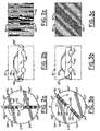
- That light energy 34 which is dispersed vertically in the Fourier transform pattern 32 ( Figure 1), emanated originally from, and corresponds to, all of the substantially vertically oriented features or details in the image 12', such as the substantially vertical lines 66, 66' in Figure 2b.
- the light energy 34 from the more intricate or closely spaced vertical parts or lines 66 i.e., higher spatial frequency
- the light energy 34 from the less intricate or farther spaced apart vertical parts or lines i.e., lower spatial frequency
- the substantially vertical parts or lines 66' in the trunk and rear bumper portions of the image 12' in Figure 2b are dispersed not so far from the optical center or axis 40.
- the intensity of the light energy 34 in those respective dispersion bands depends on the brightness of the corresponding respective vertical features 66, 66' in the image 12'.
- the central portion 53 of the rotor 54 can be blocked, if desired, because the light energy 54 in and near the center 40 of the Fourier transform 32 (Figure 1) emanates from features in image 12' with very low spatial frequencies, such as the overall brightness of the image, which do very little, if anything, to define shapes.
- the light energy 34 that passes through the slit 52 and which characterizes the vertically oriented features, parts, or lines 66, 66' of the image 12', when the slit 52 is oriented vertically, as shown in Figure 2a, is diffracted by the slit 52 and projected via beam splitter 64 to the two detector arrays 82a, 82b, which are spaced the focal distance F of FT lens 30 from the spatial filter 50.
- the diffraction of the light energy 34 by slit 52 redistributes the light energy 34 that passes through slit 52 into substantially vertically oriented bands 62 in the diffraction pattern 60, as illustrated in Figure 2c, at the detector arrays 82a, 82b ( Figure 1).
- the light energy bands 62 in Figure 2c are detected by detector arrays 82a, 82b for recording the vertically oriented shape characteristics of the image 12', as will be described in more detail-below.
- the slit 52 of spatial filter 50 rotates, as indicated by arrow 59.
- the angular position of the slit 52 shown in Figure 3a is approximately 45 degrees from vertical.
- the light energy 34 that passes through the slit 52 corresponds to all of the features, parts, or lines 67 in image 12' that are oriented at about 45 degrees from vertical, as illustrated in Figure 3b.
- Portions of curved features, parts, or lines 67' in the image 12' that are oriented at about 45 degrees from vertical also contribute to the light energy 34 that passes through the slit 52, when it is rotated to about 45 degrees from vertical, as shown in Figure 3a.
- the bands 62 of light energy in the filtered pattern 60, shown in Figure 3c, resulting from the 45-degree angular orientation of slit 52 in Figure 3a, are also oriented at about 45 degrees from vertical and are indicative of the shape characteristics 67,67' of image 12' that are oriented at about 45 degrees from vertical.
- detection of the light energy bands 62 in Figure 3c by detector arrays 82a, 82b facilitates encoding and recording of the 45-degree oriented shape characteristics of the image 12', as will be described below.
- the light energy 34 that passes through slit 52 is characteristic of all of the substantially horizontal features, parts, and lines 68 of the image 12', as shown in Figure 4b. Portions of curved features, parts, or lines 68' in the image 12' that are substantially horizontal also contribute to the light energy 34 that passes through the horizontal slit 52 in Figure 4a.
- the bands 62 of light energy in the filtered pattern 60, shown in Figure 4c, resulting from the horizontal orientation of slit 52 in Figure 4a, are also oriented substantially horizontal and are indicative of the shape characteristics 68, 68' of image 12' that are oriented substantially horizontal.
- detection of the light energy bands 62 in Figure 4c by detector arrays 82a, 82b facilitates encoding and recording of the horizontal shape characteristics of the image 12', as will be described below.
- any particular angular orientation R of slit 52 will allow detection of all the shape characteristic of image 12' that have substantially that same angular orientation R.
- all of the shape characteristics of the image 12' can be detected by detecting the bands 62 of the filtered pattern 60 with the slit 52 at all angular orientations.
- the rotor 54 with its slot 52 can be rotated continuously.
- the light energy bands 62 are detected and recorded at each selected increment or angular orientation, such as at every 11.25-degree increment of rotation.
- the image handling apparatus 20 switches the next image 14 into the optical image characterizer 10, as indicated by arrow 16 in Figure 1.
- the shape characterizing and detecting process described above is performed on the image 14 as the slit 52 rotates one-half of a revolution.
- the next image is switched into the optical image characterizer 10, and the process can cycle in this manner indefinitely, as long as there are additional images n available for characterizing, encoding, and recording.
- the detection of the light energy bands 62 in the filtered images 60 for each angular orientation of slit 52 can be accomplished with any photodetector that has the capability of detecting and outputting electric signals that are indicative of intensity of light energy on a spatial basis, such as on a pixel by pixel basis.
- a video camera or an electronic still camera with a CCD (charge coupled device) array could be used, as would be well within the capabilities of persons skilled in the art.
- FIG. 1 Another feature of this invention is the use of two photodetectors 80a, 80b, as shown in Figure I, each of which has a small array 82a, 82b of photosensitive elements or transducers 84a,84b, respectively, which form pixels
- the two photodetectors 80a, 80b can, for convenience, sometimes be called, collectively, a photodetector.
- One of the photodetector arrays 82b is virtually offset in relation to the other photodetector array 82a with reference to the optical axis 40 by one-half pixel vertically and by one-half pixel horizontally.
- This arrangement of two small photodetector arrays 82a, 82b, in combination with appropriate software facilitates precise intensity and spatial location light energy detection with minimal data handling requirements.
- the preferred embodiment of this invention uses two detector arrays 82a, 82b to detect the light energy 62 in the filtered pattern 60, although one photodetector with an array of photodetector elements could also be used.
- the two detector arrays 82a, 82b are depicted in figure 1 as parts of two separate photodetectors 80a, 80b, although the entire assembly of photodetectors 80a, 80b with their arrays 82a, 82b could be one photodetector apparatus and is sometimes referred to collectively in this description specification as a photodetector in a generic sense to cover both singular and plural photodetector apparatus.
- the advantage of two detector arrays 82a, 82b is that, by virtual offsetting the photosensor elements 84a, 84b of the arrays 82a, 82b in relation to each other with respect to the optical axis 40 or filtered pattern 60, and with a fairly simple comparator circuit or a simple software algorithm, the intensity of light energy 62 at various locations in the filtered pattern 60 can be detected accurately and precisely enough for purposes of image shape characterization according to this invention, but with less data than would be required for a conventional single photodetector array.
- the diffracted beam 61 carrying the filtered pattern 60 is split by a beam splitter 64, such as a half-silvered mirror, so that preferable, but not essentially, about half the light energy in diffracted beam 61 is transmitted as beam segment 61 a to the first detector array 82a, while the other half of the light energy in filtered beam 61 is reflected as beam segment 61 b to the second detector array 82b.
- Both beam segments 61a, 61b carry the filtered pattern 60, which has the light energy 62 filtered into bands that are unique to the image 12', as explained above.
- the intensity outputs of the photosensitive elements 84a, 84b of one or the other of the arrays 82a, 82b would have to be adjusted up or down electronically or in software in order to make the intensity comparisons and selection for data storage, which comparisons and selection are described below in more detail.
- Both of the detector arrays 82a, 82b are positioned the same optical distance F from the spatial filter 50, so virtually identical light energy 62 distributions in the spatial domain are incident on both of the detector arrays 82a, 82b.
- one of the photodetectors 80a, 80b is offset from the optical axis 40 in virtual relation to the other.
- the center line 86a of photodetector 80a is aligned with the optical axis 40 of beam segment 61a, while the center line 86b of photodetector 80b is offset from the optical axis 40 of beam segment 61b, as indicated by arrows 88, 89.
- the second detector array 82b is offset vertically by a distance equal to one-half the width of photosensitive element 84a, 84b, as indicated by arrow 88, and it is further offset horizontally by a distance equal to one-half the height of a photosensitive element 84a, 84b, as indicated by arrow 89.
- An individual photosensitive element 84a of array 82a is therefore in virtual, partial juxtaposition to four (4) adjacent photosensitive elements 84b of detector array 82b.
- the filtered pattern 60 from Figure 3c i.e., with the slit 52 in Figure 3a rotated to 45 degrees
- the light energy 62 incident on the photosensitive element 84a in column 7a, row 6a, of detector array 82a will not be the same as the light energy 62 incident on the corresponding photosensitive element 84b in column 7b, row 6b, of detector array 82b.
- the light energy 62 incident on the photosensitive element 84a in column 7a, row 6a, of detector array 82a will be less than the light energy 62 incident on the photosensitive element 84b in column 7b, row 6b, of detector array 82b.
- the situation of each photosensitive element 84a, 84b with respect to incident light energy will change for different filtered patterns 60 from different angular orientations of the slit 52 for the same image 12' and will also change for different filtered patterns 60 from different original images 12, 14, ..., n ( Figure 1) characterized by the optical image characterizer 10.
- the different incident light energy intensities on partially juxtaposed photosensitive elements 84a, 84b of the respective virtual offset detector arrays 82a, 82b are used according to this invention to encode and store shape characteristic data of images 12, 14,..., n efficiently and with sufficient of the data, as will be described in more detail below.
- detector arrays 82a, 83b comprised of 16 columns and 16 rows of photosensitive elements 84a, 84b, respectively for efficient use of bytes and data base storage.
- the photosensitive elements 84a, 84b can be photo diodes, photo cells, or any other photosensitive device that produces an electric signal, such as a voltage, which is indicative of intensity of light energy incident on the photosensitive element.
- each photosensitive element 84a, 84b in each array is readable individually, as is well-known to persons skilled in the art, and electric signal processing circuits for reading, processing, and recording such signals from arrays of photosensitive elements are well-known to persons skilled in the art Therefore, no further explanation of photosensitive elements or electric circuits for reading, processing, and recording information from arrays of photosensitive elements is needed to describe or to understand this invention.
- the intensities of light energy 62 incident on the photosensitive devices can, but does not have to, be recorded at 11.25-degree angular increments of rotation of the slit 52 of spatial filter 50, through 180 degrees of rotation, as described above.
- the use of 11.25-degree angular increments is sufficient to collect enough shape-related data for each image 12, 14, ..., n to provide fast, meaningful, and efficient characterization, storage, search, and retrieval of images, and 11.25 degrees divides 180 degrees by 16, thus making efficient use of bits and data storage bytes of information.
- Other angular increments for more or less preciseness in shape characterization, and other sizes of photosensitive arrays for more or less preciseness in shape characterization can certainly be used in this invention.
- the virtually offset detector arrays 82a, 82b improve precision of light energy detection on an element-by-element basis with the relatively few, large photosensitive elements 84a in detector array 82a, e.g., only 256 photosensitive elements 84a in a 16 x 16 detector array 82a.
- only light energy intensities for 256 locations, i.e., for a 16 x 16 array have the potential to be recorded for each angular orientation of the slit 52. Since the number of photosensitive elements 84a in the 16 x 16 detector array 82a is relatively small, the surface area segment of the filtered pattern 60 from which each photosensitive element 84a detects light energy 62 is relatively large.
- each one detecting light energy from relatively larger area segments of the filtered pattern 60 is that much less data is generated, thus much less data has to be processed.
- a disadvantage for this application i.e., characterizing images by shape content, is the probability that some small area, but high intensity light spots or energy distributions in the filtered pattern 60 may be incident on small portions or surface areas of more than one photosensitive element 84a, thus would have the intense light energy spread over several photosensitive elements 84a instead of one.
- Such high intensity spots or zones are important to detect, but when the light energy is spread over several photosensitive elements 84a, thereby splitting the intense light energy among two or more photosensitive elements 84a, the intensity signal outputs will be lower than if all of the light energy was incident on one photosensitive element.
- Such resulting lower intensity signal outputs from the several photosensitive elements 84a and the consequent failure to capture and record the high intensity light energy, which is really incident on the detector array, would result in loss of significant shape information about the image 12', i.e., bright, sharp details or lines in the image 12'.
- Figure 6 is an enlarged view of several photosensitive elements 84a of the detector array 82a virtually overlaying several offset photosensitive elements 84a of the detector array 82a as described above.
- a band 62 of light energy has a concentration or zone 63 of intense light energy that happens to straddle boundaries 92, 94, 96, 98 between four individual photosensitive elements 84a of detector array 82a those four photosensitive elements 84a are in column 5a, row 3a; column 6a, row 3a; column 5a, row 4a; and column 6a, row 4a.
- Those four photosensitive elements 84a are denoted for convenience as C5a-R3a, C6a-R3a, C5a-R4a, and C6a-R4a, with C standing for column and R standing for row.
- the corresponding spot or zone 63 of intense light energy in beam 61 is incident largely within the single photosensitive element 84b that is in column 5b, row 3b (i.e., C5b-R3b) of the detector array 82b. Therefore, the electric signal output of photosensitive element C5b-R3b of detector array 82b will be much more indicative of the high intensity of the light energy in the soot or zone 63 than the electric signals produced by any of the four photosensitive elements at C5a-R3a, C6a-R3a, C5a-R4a, or C6a-R4a of the detector array 82a.
- a data array 130 (dubbed here as a RIXel array) has the same configuration as one of the detector arrays 82a, 82b.
- the RIXel array 130 is a 16 x 16 array to match the 16 x 16 detector array 82a of photosensitive elements 84a.
- there is a RIXel space or position 131 (sometimes called a bin) that corresponds with each photosensitive element 84a in detector array 82a.
- an intensity I associated with the photosensitive element 84a at C7a - R5a of detector array 82a will be recorded in the corresponding space or bin 131 at C7 - R5 of the RIXel array 130.
- the previous sentence refers to intensity I "associated with" a particular photosensitive element, instead of "produced by,” because the intensity I recorded in a RIXel array space 131 may, but not necessarily, be the intensity produced by the corresponding photosensitive element 84a in detector array 82a.
- RIXel array 130 At each selected angular orientation of the slit 52, only enough data spaces or bins 131 are provided in RIXel array 130 to receive intensity signals from the same number of photosensitive elements 84a as there are in one array 82a. However, in order to capture the high intensity information that could otherwise get lost, before the value of the electric signal output of each photosensitive element 84a in detector array 82a is recorded permanently, it is compared with signals produced by each of the partially juxtaposed photosensitive elements 84b of detector array 82b. The highest intensity signal found by this comparison is the one that is selected for possible permanent record in RIXel array 130.
- the high intensity spot or zone 63 illustrated in Figure 6 will cause the photosensitive element 84b at C5-R3 in detector array 82b to produce a high intensity signal, while each of the four (4) photosensitive elements 84a at C5a-R3a, C6a-R3a, C5a-R4a, and C6a-R4a in detector array 82a will produce lower intensity signals.
- the signal produced by the photosensitive element 84a located at C5a-R3a is selected for permanent record in the space 131 at C5-R3 in the RIXel array 130, it is compared to the intensity signals produced by each of the four photosensitive elements 84b in array 82b that are partially juxtaposed to element C5a-R3a, i.e., photosensitive elements 84b of array 82b that are located at C4b-R2b, C5b-R2b, C4b-R3b, and C5b-R5b.
- the intensity I signal which will be selected for recording in that space 131 at C5-R3 in the RIXel will be the one produced, not by the corresponding photosensitive element 84a at C5a-R3a of detector array 82a, but the higher intensity signal produced by the photosensitive element 84b at C5b-R3b in detector array 82b.
- Intensities that do not meet the threshold intensity are not indicative of significant shape content in the image 12', thus are not recorded, as will be explained in more detail below.
- the intensity signal from photosensitive element 84b at C5b-R3b would most likely exceed such a threshold and would be recorded as the intensity I in space 131 at C5-R3 of RIXel array 130 (corresponding to the photosensitive element 84a at C5a-R3a in detector array 82a) for the permanent shape characterization record for image 12.
- each of the other three photosensitive elements 84a in array 82a on which light energy in spot or zone 63 is incident i.e., those at C6a-R3a, C5a-R4a, and C6a-R4a
- the respective photosensitive elements 84b of array 82b that are partially juxtaposed to those photosensitive elements 84a.
- the signal output of element 84a at C6a-R3a will be compared to the respective output signals of the partially juxtaposed elements 84b at C5b-R2b, C6b-R2b, C5b-R3b, and C6b-R3b; the signal output of element 84a at C5a-R4a will be compared to the respective output signals of the partially juxtaposed elements 84b at C4b-R3b, C5b-R3b, C4b-R4b, and C5b-R4b; and the signal output of element 84a at C6a-R4a will be compared to the respective output signals of the partially juxtaposed elements 84b at C5b-R3b, C6b-R3b, C5b-R4b, and C6b-R4b.
- the intensity signal produced by the photosensitive element 84b at C5b-R3b will be the highest.
- that high-intensity signal will be used for the RIXel data base 130 positions 131 corresponding not only with photosensitive element 84a at C5a-R3a in detector array 82a, as described above, but also with the photosensitive elements 84a at C6a-R3a, C5a-R4a, and C6a-R4a in detector array 82a.
- a small array (e.g., 16 x 16) can be used for detecting and recording the high intensity shape characterization data by using two juxtaposed detector arrays 82a, 82b with their respective photosensitive elements 84a, 84b partially offset in virtual relation to each other with reference to the filtered pattern 60.
- This arrangement allows unambiguous detection of spots or zones 63 of high intensity light energy by capturing energy of such spots or zones 63 that straddle one or more photosensitive element boundaries 92, 94, 96, 98 in one detector array 82a with one or more partially juxtaposed photosensitive elements 84b in the other detector array 82b.
- This offset, virtual juxtaposed use of two detector arrays 82a, 82b facilitates very rapid detection of high intensity light energy 62 concentrated in spots or zones 63 at particular locations in the filtered pattern 60, even if the photosensitive elements 84a, 84b are larger in area than the spot or zone 63 sizes.
- Disadvantages of this arrangement include inability to discriminate between very closely spaced high intensity spots or zones, inability to determine precise shapes of such high energy spots or zones 63, and recording high intensity values from such spots or zones in multiple spaces 131 in RIXel array 130 representing larger areas of the filtered pattern 60 than the spots or zones 63 really cover in circumstances where such high intensity spots or zones 63 straddle boundaries between photosensitive elements 84a.
- this invention can be used with just one detector array 82a, especially in the preferred embodiment of Figure 1, in which the Fourier transform pattern 32 is filtered through a slit 52, which diffracts the filtered light. Such diffraction tends to disperse light energy rather than concentrating it into spots. Still, significantly more preciseness is provided by the two offset, juxtaposed detector arrays 82a, 82b with insignificantly additional processing to compare and select the intensity I as described above. For that matter, even more preciseness could be provided by more than two offset, juxtaposed detector arrays, such as three or four, especially if even smaller arrays, such as 8 x 8 arrays, are used.
- the selection of the highest intensity signals during the comparison of partially juxtaposed photosensitive elements 84a, 84b, as described above, can be done in a number of ways that are well within the capabilities of persons skilled in the art, such as routing the signal outputs of each photosensitive element 84a, 84b through a network of voltage comparator circuits or by software comparison and selection processes. Therefore, such details are not necessary for describing or understanding the invention.
- the computer 100 gathers and coordinates intensity signals (I), which are indicative of shape content of the image 12 at the specific angular increments 51 of rotation (R) of the slit 52 as the rotor 54 spins on its axis 57.
- the rotation R information and related intensity I is put together in a "RIXel" data array 130, as will be explained in more detail below.
- an information link 132 between the computer 100 and the image handling apparatus 20 handles signals between the computer 100 and the image handling apparatus 20.
- the computer 100 can signal the image handling apparatus 20 to insert a particular image 12, 14, ..., n into the optical characterizer 10.
- Signals from the image handling apparatus 20 can communicate the identity of the image 12 to the computer 100 and confirm that it has been inserted.
- the image identity can be an arbitrary number or any other symbol or information that can be associated by the computer 100 with the RIXel data arrays 130 and with information about the image 12 such as where it can be found, e.g., a URL address, data base address, library catalog number, owner, museum collection, or the like.
- an encoder 134 detects angular position of the slit 52 and sends a signal via a communication link 136 to the computer 100, which signal indicative of a particular angular rotation position R of the slit 52.
- the encoder 134 can be, for example, apparatus in which a photocell (not shown) detects light from an LED or other light source (not shown), which passes through the encoder holes 138 in the periphery of the rotor 54, as would be understood by a person skilled in the art.
- the encoder 134 can send a signal via communication link 136 at each instant the rotor 54 rotates another 11.25 degrees.
- the computer 100 can use the signals from encoder 134 to trigger a read of intensity information I from the detector arrays 82a, 82b, or from a separate intensity signal processing circuit 150 between the detector arrays 82a, 82b and the computer 100, and to keep track of the angular rotation R of the slit 52 for each such intensity I reading.
- a separate rotation R signal processing circuit 140 could be used to calculate angular rotation position R of the slit 52 from encoder 134 signals and to output that rotation position R information of the slit 52 along with a signal to the computer 100 to read intensity I each time the rotor 54 turns another 11.25-degree angular increment, or, for that matter, each time the rotor 54 turns any desired angular increment.
- the encoder holes 138 do not have to match the desired angular increments of rotation R at which intensity I is to be read by computer 100.
- Either the computer 100 or the microprocessor 140 could be programmed to keep track of rotation speed, i.e., angular velocity, and rotation position R with any encoder hole 138 spacing and to generate intensity read signals at any desired angular increments of rotation R. Therefore, controls could be provided on either the signal processing circuit 140 or in the computer 100 to vary the angular increments of rotation R of the slit 52 at which intensities I are read. It is convenient and simple, however, to place the encoder holes 138 at the desired angular increments of rotation R, such as for mass production of image characterizer apparatus 10 after a desired angular increment has been determined.
- the filtered beam 61 passed by the slit 52 in spatial filter 50 is projected onto the offset detector arrays 82a, 82b, where the light energy distributions 62 are detected on a real time basis by individual photosensitive elements 84a, 84b of the detector arrays 82a, 82b.
- the intensity I for each RIXel in array 130 at each angular rotation increment R will be selected from the highest intensity of a corresponding photosensitive element 84a in detector array 82a or one of the four photosensitive elements 84b in detector array 82b, which are partially juxtaposed to the corresponding photosensitive element 84a.
- selecting the intensity I from either the photosensitive element 84a or one of the four partially juxtaposed photosensitive elements 84b can be done with software in the computer 100, but is preferably done with a separate intensity I signal processing circuit 150 positioned between the detector arrays 82a, 82b and the computer 100.
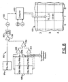
- the intensity I image processing circuit 150 can be hard wired with an array of voltage comparator circuits 152, an example of which is illustrated diagrammatically in Figure 8, or with a microprocessor circuit (not shown), as would be well-known to persons skilled in the art.
- the intensity I associated with an example photosensitive element 84a is the highest intensity produced by the particular photosensitive element 84a or by any of the four partially juxtaposed photosensitive elements 84b.
- the same photosensitive element 84a that was discussed earlier, i.e., in column 7a, row 5a (C7a-R5a) of the detector array 82a ( Figures 5, 6, and 7) is used as an example.
- a photosensitive element 84a which is usually a voltage level
- the intensity signal produced by a photosensitive element 84a is compared to the four photosensitive elements 84b in detector array 82b that are partially juxtaposed to the C7a-R5a element 84a in detector array 82a.
- those four partially juxtaposed elements 84b are at C6b-Rb, C7b-R4b, C6b-R5b, and C7b-R5b in detector array 82b.
- the output voltages of two of the elements 84b at C6b-R4b and C7b-R4b are compared by comparator circuit 152, which outputs the highest of those two voltages, while the output voltages of the other two elements 84b at C6b-R5b and C7b-R5b are compared by comparator circuit 154, which outputs the highest of those two voltages.
- the respective output voltages of comparator circuits 152, 154 are then compared by comparator circuit 156, which outputs the highest voltage from the four individual elements 84b. That highest voltage from the elements 84b is then compared by the comparator circuit 158 to the output voltage produced by the element 84a (C7a-R5a).
- Whichever voltage is highest from among the single photosensitive element 84a at C7a-R5a and the clustered group of partially juxtaposed photosensitive elements 84b at C6b-R4b, C7b-R4b, C6b-R5b, and C7b-R5b will be the voltage that is sent to the amplifier and analog to digital (A/D) converter circuits 160 for processing and feeding as the intensity I via communication link 162 to the computer 100.
- A/D analog to digital
- the intensity I associated with the one photosensitive element 84a at C7a-R5a of detector array 82a determined as discussed above, it is only one of the intensities I from the 16 x 16 detector array 82a being processed by the comparator circuit 150, as described above, and fed to the computer 100 via communications link 162 on a real time basis.
- the computer 100 when the computer 100 is signaled by encoder 134 and/or the rotation R signal processing circuit 140 that a desired angular increment of rotation R has been reached by the slit 52, the computer 100 reads the 256 intensities I from the comparator circuit 150, which are associated with all of the 256 photosensitive elements 84a in the 16 x 16 detector array 82a, and feeds them into the corresponding spaces or bins 131 of the RIXel data array 130.
- the intensity I associated with the photosensitive element 84a illustrated in Figure 8, i.e., at C7a-R5a of detector array 82a, is sorted by the computer 100 to be placed along with the corresponding rotational angle R into the column 7, row 5, RIXel space 131 in the 16 x 16 RIXel array 130.
- the rest of the 256 intensities I associated with the rest of the 256 photosensitive elements 84a of the 16 x 16 detector array 82a are sorted by the computer 100 and fed along with the rotation R, which is associated with those intensities I, into the respective corresponding RIXel positions or bins 131 in the RIXel array 130.
- the computer 100 only puts intensities I that meet a specific intensity threshold into the RIXel array 130.
- intensities I that meet a specific intensity threshold into the RIXel array 130.
- intensities I associated with photosensitive elements 84a in detector array 82a that are below a certain threshold intensity level no R, I, or X data is put into the corresponding RIXel positions or bins 131 in RIXel array 130.
- intensities I above the threshold there are, according to the preferred implementation, four (4) levels into which the intensities I are categorized, i.e., 0,1,2, or 3. Therefore, only two (2) bits are needed to record each intensity I in RIXel array 130 i.e., 00,01,10,or 11.
- intensity I levels would require more bits.
- eight (8) intensity I levels would require three (3) bits to record, and sixteen (16) intensity I levels would require four (4) bits.
- the "X" data space in each RIXel is used for a distortion factor to aid in searching and finding images with almost, but not exactly, the same shape characteristics, or in finding images that have the same shape characteristics, but which might be shifted slightly in the field of view, as will be described in more detail below.
- the "X" data space could also be a flag used for some other purpose in data base searching or for higher rotation R precision or for higher intensity I precision.
- the "X" can have up to four (4) values -0, 1, 2, 3, so it could be stored with two (2) bits of data information.
- the R value in the RIXel has four (4) bits to encode rotation R, which is sufficient for the 16 rotation R increments of 11.25 degrees each, in 180 degrees of rotation.
- Two (2) bits are used to encode the intensity I, as explained above, and two (2) bits are used to encode the X distortion factor or other flag usage, as also explained above. Therefore, each RIXel has just eight (8) bits, i.e., one (1) byte of information.
- the "X" space in the RIXel is preferably used as a distortion factor, which can be assigned to RIXels in the RIXel array 130 that are otherwise unused or unfilled due to intensity I below the threshold intensity level, in order to provide several different searchable levels of distortion in the searchable data. Therefore, if a searcher has an image for which he/she wants to find a match, but, in a search of the data base, cannot find a matching image from among the RIXel information stored for images 12, 14, ..., n in the data base when using exact RIXel information, then the searcher may widen the search to look for inexact matches by specifying a different X value in the RIXels.
- Figure 9a a portion of the RIXel array 130, comprising primarily columns 0 - 8, rows 9 - 15, are illustrated with example RIXel values R, I, and X in several of the RIXel positions or spaces in the RIXel array 130.
- some of the RIXel positions or spaces in the array 130 are empty, because the intensities I associated with the corresponding photosensitive elements 84a in detector array 82a did not meet the minimum intensity threshold.
- the computer 100 initially made no RIXel entries in those spaces or positions in array 130, leaving all of columns 0, 1, 2, 8 in rows 9,10,11,12,13,14,15; column 3, rows 9, 10, 11, 14, 15; column 4, rows 9, 10, 13, 14, 15; column 5, rows 9, 12, 13, 14, 15; column 6, rows 11, 12, 13, 14, 15, and column 7, rows 10,11,12,13,14,15 empty.
- the slit 52 rotates another 11.25-degree increment to 56.25 degrees, a new RIXel array 130 will be filled with new intensity I values.
- ID# unique image identifier number
- the copy has the image shifted slightly up or down, or left or right, in the field of view.
- the user puts the copy of the image into the optical image characterizer 10 of this invention and obtains RIXel data that characterizes the shape content of the copy.
- the RIXel information of the characterized shape content of the copy would be the same, or very nearly the same, as the RIXel information of the characterized shape content of the original image 12.
- the RIXel characterizations of shape content of the copy i.e., the reference image
- the RIXel data of the original image 12 in Figure 9a being in slightly different RIXel array 130 columns and rows than the corresponding image copy RIXel information, might not be identified as a match in the search.
- the computer 100 has filled some of the previously emply RIXe1 spaces, 131 to the extent of three spaces 131 horizontally and three spaces 131 vertically from the closest originally filled spaces 131, with R, I, and X RIXel values.
- each additional RIXel space 131 that is removed vertically or horizontally from an originally filled space 131 is assigned a step lower X value, i.e., increasing distortion, the farther the RIXel space 131 is removed from an original filled RIXel space 131.
- the idea is to be able to search and find the same, or nearly the same, RIXel intensity I patterns for a particular rotation R, even if the spatial locations of the RIXels that store those intensity I values are slightly offset in the RIXel array 130.
- the searcher may be enabled by the search software to specify desired levels of RIXel matching. For example, a user may look for a match of, say, 70 percent of the RIXels and to get the identifier information for all original images 12, 14, ..., n for which 70 percent of the RIXels were matched in the search. If the search returns too many matches at the 70 percent level, the user could do another search specifying a higher, or more precise, match level, such as, reporting only identifying information for images for which, say, 80 percent or 90 percent of the RIXels match.
- the RIXel information for an image 12 can be distributed by the computer 100 to build a shape vector data base 102 in any number of arrangements and with any subject or variety of other information, as illustrated in Figure 1, depending on what criteria users may desire for storing, searching, and retrieving information about the images 12, 14,..., n.
- one date base structure 104 may list the RIXel data under a specific image identifier (such as an ID#, of an image) along with location information for the image (such as URL address where the image 12 is located in the Internet), format and resolution information (such as rotation increments, detector array sizes, and the like), color information (which can be provided manually or by an automated optical color characterizer (not part of this invention)), texture information (which can also be derived from other automated optical texture characterizer (e.g., the U.S. patent application serial no. 09/326,362)), and the like.
- Another data base arrangement 106 may list identifier numbers or designations of all images 12, 14,..., n by RIXel characterizations of shape content.
Landscapes
- Engineering & Computer Science (AREA)
- Theoretical Computer Science (AREA)
- Physics & Mathematics (AREA)
- General Physics & Mathematics (AREA)
- Multimedia (AREA)
- Library & Information Science (AREA)
- Data Mining & Analysis (AREA)
- Databases & Information Systems (AREA)
- General Engineering & Computer Science (AREA)
- Computer Vision & Pattern Recognition (AREA)
- Image Analysis (AREA)
- Image Processing (AREA)
- Compression Or Coding Systems Of Tv Signals (AREA)
Abstract
Description
- This patent application is a continuation-in-part of U.S. patent application serial no. 09/326,362, filed in the U.S. Patent and Trademark Office on June 4, 1999.
- This invention relates generally to optical image processing and more particularly characterizing images optically in a way that can be encoded, stored, searched, retrieved, and/or compared to other images.
- There are hundreds of millions, perhaps billions, of creative works in the world which are in the form of visual images or which can be converted into visual images. Such creative works may include, for example, artistic drawings and paintings, commercial art, technical drawings, photographs, motion pictures, digitally recorded still and video motion images, radar images, maps, computer-generated images, literary works, graphics software code, sound recordings, and many more. Such creative works are stored in libraries, data bases, public and private collections, and other places all over the world, and there are many reasons for persons wanting to find them. However, images are much more difficult than, for example, text, to characterize in an objective manner, independent of human viewing and subjective evaluation. Therefore, creation of a comprehensive data base for storing and searching large numbers of images has been a daunting task and the results have limited utility, even when augmented by computerized indexing and searching. For example, a visual search engine implemented by ditto.com (formerly Arriba Soft Corp.) uses a "crawler" computer software program to travel the World Wide Web, visiting web sites in search of images, and capturing the images along with any related text. The images are then reduced in size, indexed with the text according to some category of subject matter, content, characteristic, or the like, screened and/or chosen by humans ("human filters"), and entered into a data base. Subsequent access or searching of the data base is done by entering a key word or phrase, which has to be one of a number of key words or phrases that the search engine architect or operator has chosen to characterize an image in the search engine index. For example, a searcher could enter the word "butterfly" and, if the data base search engine has images indexed by the word "butterfly," the search engine will display those images. If the search under "butterfly" yields too many hits, e.g. over 3000 images, another word, such as "monarch" can be added to narrow the search field, but only if the data base architect or operator has images indexed under the word "monarch". The words "monarch butterfly" may narrow the field t, e.g., several hundred images. It is then up to the human viewer to look at all the images catalogued under the words "monarch" and "butterfly" to see if there is one or more of interest. Ultimately, the search capability of such a search engine is limited by: (i) the word(s) the data base architect or operator choose to describe an image; (ii) the limited time that real people have to view the images, assign key words for indexing, and enter the image with the chosen index words in the data base-currently up to several million images; (iii) the limited images from the hundreds of millions or billions available that the operator decides to index and put into the data base; (iv) the user has to personally view the images presented; and (v) if the user wants to find the source or location of an image of which the user has a reference image that the user has in his/her possession, the user has to hope the search engine operator did not exclude the wanted image, and the user has to compare the images delivered by the search engine to the reference image.
- Applicant's co-pending patent application, U.S. Serial No. 09/326,362, filed June 4, 1999, describes how images can be found in various data bases, servers, web sites, and the like that are accessible by or via the Internet and compared to a reference image using optical correlation techniques. However, it is not very desirable or efficient to have to search through all such available sources each time a match is sought for a different reference image. Of course, all of the images found in all such available sources could be placed into a single or central data base, and then each search for a match to a reference image could be searched in that data base. Such a scheme would eliminate having to go to all available sources for each search. However, many images require hundreds or thousands of kilobytes of data, so it would require a massive data storage memory to gather and store the hundreds of millions or billions of images together in one data base, and searching through all such images for every reference image would still be inefficient, even if all the images were in a single data base. Yet, attempts to limit searching time and resource requirements by arbitrary categories, while possibly beneficial to a limited extent, imposes at least some of the limitations and inefficiencies described above in relation to the ditto.com types of image search engines. Applicant's copending patent application, serial no. 09/326,362, does not address how images found in such various data bases, servers, web sites, and the like could be characterized in a manner that requires minimal data or bytes of information for easy and manageable data base storage, quick searching, and ready retrieval for match comparisons.
- There is a need for a more automated, high-speed apparatus and method for characterizing images in a manner that can be stored, searched, retrieved, and compared to a reference image with minimal, if any, human intervention or participation.
- Accordingly, it is a general object of this invention to provide an improved apparatus and method for characterizing images with information that is unique for each image and that is suitable for encoding, storing, and searching in a data base.
- A more specific object of this invention is to provide a method for characterizing shapes in an image quickly and encoding such shape-related characteristics with minimal data so that data storage, searching, and retrieval can be done fast and without extraordinary computer processing power and memory capacity.
- Another specific object of the invention is to provide automated search and retrieval of an image from a data base of images based on a reference image.
- This and other objects, advantages, and novel features of the invention shall be set forth in part in the description that follows, and in part will become apparent to those skilled in the art upon examination of the following description or may be learned by the practice of the invention. The objects and the advantages may be realized and attained by means of the instrumentalities and in combinations particularly pointed out in the appended claims.
- To achieve the foregoing and other objects and in accordance with the purposes of the present invention, as embodied and broadly describe herein, the method of this invention as defined in
claim 1 includes characterizing an image for shape content by creating an optical Fourier transform pattern of the image with light energy, spatial filtering the light energy from the Fourier transform pattern with a rotating slit to create a filtered pattern of light energy, detecting intensities of light energy as it is distributed in the filtered pattern at discrete angular orientations of the slit, and storing the intensities of light energy detected in the spatial pattern along with the discrete angular orientation of the slit at which such intensities of light energy are detected. The invention also includes splitting the light energy distributed in the filtered pattern into two beams for detecting by two separate detector arrays that are offset in virtual relation to each other in reference to the filtered pattern in order to avoid losing light energy intensities in spots or zones of light energy that straddle boundaries between two or more individual photosensitive elements in one of the detector arrays. Processing and storing the light energy intensities include combining intensities from individual photosensitive elements with angular orientation of the slit for storage in spaces of a data array that correspond to positions of individual photosensitive elements in the detector array. The intensities can be measured against an intensity threshold and stored in the data base only if they are at least as high as the intensity threshold. A flag, such as one or more distortion levels can be added to the rotation and intensity information stored in the data array. - To further achieve the foregoing objects, the apparatus of this invention as defined in claim 18 (with an alternative defined in claim 23) includes an optical image shape content characterizer comprising a Fourier transform lens for creating a Fourier transform pattern of light energy from the image at the focal plane of the lens, a spatial filter with a rotating slit positioned in the focal plane of the lens to pass only light energy from the Fourier transform pattern at angular orientations of the slit, a photodetector positioned to detect light passed by the spatial filter, and a spatial light modulator with an associated coherent light source. The spatial light modulator is addressable to produce an image with coherent light from the associated coherent light source and to project the image with the coherent light through the Fourier transform lens. The photodetector preferably includes two detector arrays of individual photosensitive elements, and a beam splitter projects a portion of the filtered pattern to one of the detector arrays and another portion to the other detector array. The detector arrays are virtually offset in relation to each other in reference to the filtered pattern. A comparator circuit (or software performing comparator function) selects intensity from among an individual photosensitive element in one of the arrays and a cluster of virtual partially juxtaposed photosensitive elements in the other array. A RIXel data base array is used to store intensities together with rotational orientation and, optionally, a searchable flag, such as a distortion factor.
- The accompanying drawings, which are incorporated in and form a part of the specification, illustrate the preferred embodiments of the present invention, and together with the descriptions serve to explain the principles of the invention.
- Figure 1 is a schematic diagram of an optical image characterizer according to this invention;
- Figures 2a - c show the relationship between the vertical angular orientation of the slit in the spatial filter (Figure 2a) in relation to the shape features in the image (Figure 2b) and the resulting filtered pattern of light energy (Figure 2c);
- Figures 3a - c are similar to Figures 2a - c, but with the angular orientation of the slit at about 50 degrees from vertical;
- Figures 4a - c are also similar to Figures 2a - c, but with the slit rotated to horizontal;
- Figure 5 is a diagrammatic illustration of the offset, virtual juxtaposed detector grids of this invention as used to detect a filtered pattern of light energy;
- Figure 6 is an enlarged portion of the virtual juxtaposed detector arrays illustrating detection of light energy spots or areas that straddle boundaries between adjacent photosensitive elements;
- Figure 7 is a functional diagram illustrating collection of image identity and RIXel rotation and intensity data for the RIXel data array;
- Figure 8 is a diagrammatic illustration of an intensity signal comparator circuit for selecting intensity from among a photosensitive element of one detector array and four partially juxtaposed photosensitive elements of the other detector array for inclusion in the RIXel data base; and
- Figures 9a - b illustrate a portion of the RIXel data base with spaces filled with rotation, intensity, and distortion information for precise searching and with additional spaces filled with different distortion value flags for less precise searching.
- An
optical image characterizer 10 for characterizing, storing, and searching optical images by shape content according to the present invention is shown schematically in Figure 1. Thischaracterizer 10 characterizes an image according to the geometric shapes that comprise the image, and the characterization will be unique to the image. Other characterizations of the image, such as color and/or texture created with different optical apparatus that is not part of this invention can be used together with the shape characteristics acquired according to this invention further characterize and search images. However, this description will focus primarily on image shape content characterization according to this invention. - Essentially, a
sample image 12, which can be obtained from any source (e.g., Internet, electronic data base, web site, library, scanner, photograph, film strip, radar image, electronic still or moving video camera, and other sources) is entered into the opticalimage shape characterizer 10, as will be described in more detail below. Any number n ofother sample images 14, ..., n, are shown in Figure queued for entry in sequence, as indicated byarrows optical image characterizer 10. Entry of any number n of suchsequential images box 20 in Figure 1 represents diagrammatically any apparatus capable of queuing and movingimages image characterizer 10. The description that follows will, for the most part, refer only to thefirst image 12 for convenience and simplicity, but with the understanding that it could apply as well to anyimage - Also, the
several sample images optical image characterizer 10 in a plane that is perpendicular to the beam of light 22 emanating from theimage illuminator 21, i.e., perpendicular to the plane of the view in Figure 1. However, to facilitate explanation, illustration, and understanding of the invention, theimages Fourier transfer pattern 32,spatial filter 10, filteredpattern 60, anddetector grids - An
image 12 entered into theoptical image characterizer 10 passes optically through a number of optical components, which will be described in more detail below. However, theimage 12 will undergo a significant transformation upon passing through the thin, positive lens 30, also called the Fourier transform (FT) lens. A Fourier transform of the sample image 12' rearranges the light energy of the image 12' into aFourier transform pattern 32, which occurs at the focal length F of the lens 30 (i.e., in the focal plane, as shown in Figure 1, and which is unique to the image 12', even though it is not recognizable as the image 12' to the human eye. The light energy in the Fourier domain, i.e., in the focal plane, can be characterized by intensities, i.e., amplitudes, of light energy distributed at various spatial positions across theFourier transform pattern 32. The complex amplitude distribution oflight energy 34 in thepattern 32 is the Fourier transform of the complex light distribution in the image 12', which is an optical recreation of theimage 12 in monochromatic, preferably coherent, light energy, as will be described in more detail below. Concentrations of intense light energy in the Fourier transform (FT)pattern 32 generally correspond to spatial frequencies of the image 12', i.e., how closely together or far apart features in the image 12' change or remain the same. For example, a shirt with a plaid fabric in an image (not shown), i.e., having many small squares in the spatial domain image, would have a higher spatial frequency, i.e., changes per unit of distance, than a plain, single-color shirt (not shown) in the spatial domain image. Also, portions of an image, such as the bumper andgrill parts 35 of the automobile in the spatial domain image 12', would have a higher spatial frequency than theside panel 36 portion of the automobile image 12', because the bumper andgrill parts 35 comprise many small pieces with various edges, curves, and other intricate changes within a small spatial distance, whereas theside panel 36 is fairly smooth and uniform over a large spatial distance. Light energy from the finer details of an image in the spatial domain, such as the more intricate bumper andgrill parts 35 of the spatial domain image 12', tend to be dispersed farther radially outward from the optical center oraxis 40 of the Fourier transformed image, i.e., in the Fourier domain, than light energy from courser or plainer details of an image, such as theside panel 36 of the spatial domain image 12'. The amplitude oflight energy 34 dispersed radially outward in the Fourier transform pattern 32 (Fourier domain) is related to the light energy of the corresponding portions of the spatial domain image 12' from which such light energy emanates, except that such light energy is concentrated into areas orbands 34 at the plane of the Fourier transform (FT)pattern 32 after they are refracted by the FT lens 30, i.e., into bands of intense light energy separated by bands of little or no light energy. If the high spatial frequency portions of the image 12', such as the bumper andgrill portion 35, are bright, then the intensity or amplitude of light energy from those high spatial frequency portions of the image 12', which are dispersed by the FT lens 30 to the more radially outward bands oflight energy 34 in theFourier transform pattern 32, will be higher, i.e., brighter. On the other hand, if the high spatial frequency portions of the image 12' are dim, then the intensity or amplitude of light energy from those high spatial frequency portions of the image 12', which are dispersed by the FT lens 30 to the more radially outward bands oflight energy 34 in theFourier transform pattern 32, will be lower, i.e., not so bright. Likewise, if the low spatial frequency portions of the image 12', such as theside panel portion 36, are bright, then the intensity or amplitude of light energy from those low spatial frequency portions of the image 12' which are dispersed by the FT lens to the less radially outward bands oflight energy 34 in the Fourier transform pattern 32 (i.e., closer to the optical axis 40), will be higher, i.e., brighter. However, if the low spatial frequency portions of the image 12' are dim, then the intensity or amplitude of light energy from those low spatial frequency portions of the image 12', which are dispersed by the FT lens 30 to the less radially outward bands oflight energy 34 in theFourier transform pattern 32, will be lower, i.e., not so bright. - In summary, the
Fourier transform pattern 32 of the light emanating from the image 12'(i) is unique to the image 12', (ii) comprises areas or bands oflight energy 34 concentration dispersed radially from the center oroptical axis 40 that represent spatial frequencies, i.e., fineness of details, in the image 12', (iii) the intensity or amplitudes oflight energy 34 at each spatial frequency area or band in theFourier transform pattern 32 corresponds to brightness or intensity of light energy emanating from the respective fine or course features of the image 12', and (iv) suchlight energy 34 in the areas or bands of theFourier transform pattern 32 are detectable in intensity and in spatial location. - However, since this
optical image characterizer 10 of this invention is designed to characterize animage 12 by shapes that comprise theimage 12, additional spatial filtering of the Fourier transformlight energy pattern 32 is used to detect and capture light energy emanating from the finer details or parts of such finer details in the image 12', which are aligned linearly in various specific angular orientations. Such spatial filtering can be accomplished in any of a number of different ways, as will be explained in more detail below, but an exemplaryspatial filter 50 arrangement for this function is anelongated slit 52 in anopaque rotor 54 positioned in the focal plane of the FT lens 30 (i.e., in the Fourier domain), which is rotatable on an axle about theoptic axis 40. A rotation drive, depicted diagrammatically in Figure 1 as amotor 56 with adrive belt 58 extending around thespatial filter rotor 54, rotates thespatial filter rotor 54, thus theslit 52, about theoptic axis 40, as indicated byarrow 59. In practice, such amotor 56 andbelt 58 drive may be used, but other, more efficient rotor apparatus, such as an air drive and air bearings (not shown) can also be used. - Only the portions of the
light energy 34 in theFourier pattern 32 that align with theslit 52 can pass through thespatial filter 50. Such portions oflight energy 54, which pass through thespatial filter 50, represent, i.e., emanated largely from details or features of the image 12', such as straight lines and short segments of curved lines, that align lineally with the angular orientation of theslit 52, will be described in more detail below. The result is a filteredpattern 60 oflight energy bands 62 that represent the unique combination of features or lines in the image 12' that align linearly with thesilt 52 in thespatial filter 50. - Of course, as the
slit 52 rotates about theoptical axis 52, as indicated byarrow 59, theslit 52 will align linearly with features or lines in the image 12' that have different angular orientations. Thus, the diffractedlight energy bands 62 in the filteredpattern 60 will change along with the rotation of theslit 52 to represent different features, details, or lines in image 12' at various angular orientations, intricateness or fineness, and brightness, as will be explained in more detail below. - The spatially filtered light energy in
bands 62 of the filteredpattern 60 can be detected by one or more photodetector(s) 80a, 80b at any of the various angular orientations of theslit 52 and fed electronically to acomputer 100 or other microprocessor for processing and encoding, as will be described in more detail below. One significant, but not essential, feature of this invention includes the use of twodetector arrays photosensitive energy transducers arrays optical axis 40. This feature facilitates detection and recording of the filteredpatterns 60 in detail, but quicker and with less data processing capacity or power than would be required with one photodetector array, as will be explained in more detail below. The spatially filteredlight beam 61 is split bybeam splitter 64 to send thebeam 61 to bothphotodetectors 80a, 80b, so that the filteredpatterns 60 are detected by bothdetector arrays - The
computer 100, with input of optical information about the filteredpatterns 60, i.e., light energy intensity (I) distribution, from the one or two detector array(s) 82a, 82b, along with information from theimage handling apparatus 20 about the image 12 (e.g., identification number, source locator, and the like), and information from thespatial filter 50 about the angular orientation (R) of theslit 52, can be programmed to encode the characteristics of theimage 12 relating to the shape content of theimage 12. One useful format for encoding such information is by pixel of the filteredimage 60, including information regarding x, y coordinate location of each pixel, Rotation (i.e., angular orientation of theslit 52, thus of the linear features of theimage 12 that align with such angular orientation), and Intensity (i.e., amplitude of light energy from the filteredpattern 60 that is detected at each pixel at the angular orientation R. A searchable flag, such as a distortion factor X, can also be provided, as will be explained in more detail below. Such combination of angular orientation or rotation R, light energy intensity I for each pixel, and distortion factor X can be called a "RIXel" for short. Each RIXel can then be associated with some identifier for theimage 12 from which it was derived (e.g., a number, name, or the like), the source location of the image 12 (e.g., Internet URL, data base file, book title, owner of theimage 12, and the like), and any other desired information about the image, such as format, resolution, color, texture, or the like. Some of such other information, such as color and/or texture can be information input from another data base or even from another optical characterizer that automatically characterizes thesame image 12 as to color, texture, or the like-whatever would be useful for searching and findingimage 12 or for comparingimage 12 to other images. - Some, all, or additional combinations of such information about each
image computer 100 to one or more data base(s) 102. Several exampledata base architectures image - In the
optical image characterizer 10 illustrated in Figure 1, theimage 12 is recreated with monochromatic, preferably coherent, light energy, e.g., at image 12' with a spatial light modulator (SLM) 26 illuminated with a beam of coherent light 24 from alaser source 23, such as a laser diode or gas diode. This feature of the invention could also be implemented with white light, although the resultant Fourier transform and spatially filtered patterns would be more blurred than with monochromatic light. Therefore, while this description of the invention will proceed based on monochromatic, preferably coherent, light, it should be understood that white light is a suitable, albeit not-preferred, substitute. The spatial light modulator (SLM) 26 can be optically addressable, such as the one illustrated in Figure 1, or it can be electrically addressable and driven, for example by a video camera (not shown) or by a computer (not shown). As is known by persons skilled in the art, a spatial light modulator can "write" an image into a polarized beam oflight 25 by rotating the polarization plane of the light on a spatial basis across thebeam 25 to either absorb or transmit the polarized light, or partially absorb or transmit the polarized light, depending on what is needed to create the image 12' in monochromatic light. In an optically addressedSLM 26, the image plane is addressed on a spatial basis by incident light energy on a semiconductor material adjacent the polarization rotating material (usually a liquid crystal material), whereas, in an electrically addressable SLM (not shown), the liquid crystal, polarization rotating material is addressed electrically on a pixel by pixel basis. In either case, portions of the polarized beam ofcoherent light 25 are either absorbed or transmitted by the liquid crystal material in theSLM 26. In some SLM's, such as the optically addressedSLM 26 shown in Figure 1, the transmitted portions of the polarized light have the plane of polarization rotated 45 degrees as it passes once through the liquid crystal material, whereupon it is reflected and passed back through the liquid crystal again to be rotated another 45 degrees. Thus, the light inpolarized beam 25 that is not absorbed in theSLM 26 is reflected and emerges from the SLM along the sameoptical path 27, but in the form of image 12' and with its plane of polarization rotated 90 degrees. Some electrically addressed SLM's work much the same way, i.e., transmitting the polarized light twice through the liquid crystal with a reflection between the two passes, while others simply transmit the polarized light through the liquid crystal once in one direction. - In the Figure 1 embodiment, the
coherent light beam 24 fromlaser source 23 is passed first through a polarizer 28 to create a polarized beam of light 25 with all the light polarized in one plane, such as, for example, but not for limitation, in the s plane, as indicated by 25(s). The s-polarized beam 25(s) is then passed through aspatial filter 110 comprised essentially of apin hole 112 and a lens 114 to focus the beam 25(s) on thepin hole 112. Thisspatial filter 110 is provided primarily to condition the beam 25(s) to get a good Gaussian wavefront and, if necessary, to limit the power of the beam 25(s). Lens 114a then columnates the light. - The beam 25(s) is then passed through a polarizing beam splitter 116, which reflects light polarized in one direction at
plane 118 and transmits light polarized in the orthogonal direction. In this example, the polarizing beam splitter 116 reflects s-polarized light and transmits p-polarized light, and it is oriented to reflect the s-polarized beam 25(s) toward the optically addressed spatial light modulator (SLM) 16. - At the same time, the
light beam 22 fromilluminator 21, such as a laser diode or gas laser, illuminates theimage 12. As mentioned above, there are many other ways to put theimage 12 into theoptical image characterizer 12, such as with a cathode ray tube, SLM video display, mechanical slide projector, movie projector, and many more, as will be apparent to persons skilled in the art. For simplicity, theimage 12 is illustrated in Figure 1 on transparency orfilm 120, placed in asupport 122 in the path ofbeam 22. A light diffuser plate 124, such as a frosted or etched glass, can be positioned in front of thefilm 120 to obtain a uniform illumination of theimage 12. Thebeam 22 carryingimage 12 is then projected (focused) onto the optically addressable spatial light modulator (SLM) 26 by alens 126. Thespectral mirror 128 is optional. It is used here to fold thebeam 22 in order to keep the optics in a more compact arrangement. - With the
image 12 focused onto theSLM 26, theSLM 26 imparts or "writes" theimage 12 into the monochromatic light beam 25(s), which emerges from theSLM 26, as described above, with its plane of polarization rotated 90 degrees. Therefore, the emerging beam 27(p) of coherent light, carrying image 12', is p-polarized instead of s-polarized. Consequently, the monochromatic light beam 27(p) with the image 12' is transmitted by the polarizing beam splitter 116 to the FT lens 30, instead of being reflected by it. - The positive FT lens (30), as explained above, redistributes the monochromatic light energy in the image 12' into its
Fourier transform pattern 32, which occurs at the focal plane of the FT lens 30. Therefore, thespatial filter 50 with therotating slit 52 has to be positioned in the focal plane of the FT lens 30, as indicated by the focal distance F in Figure 1. As also explained above, the complex amplitude distribution oflight energy 34 in theFourier transform pattern 32 at the focal plane of the FT lens 30 is the Fourier transform of the complex amplitude distribution in the image 12'. TheFourier transform pattern 32 has all of the light energy from the image 12' distributed into thesymmetrical pattern 32 based on the spatial frequencies of the image 12', with intensities of the light energy in the variousspatial frequency distributions 34 based on the light energy in the corresponding portions of the image 12' where those respective spatial frequencies occur. TheFourier transform pattern 32, as mentioned above, is symmetrical from top to bottom and from left to right, so that each semicircle of theFourier pattern 32 contains exactly the same distribution and intensity of light energy. Light energy from lower spatial frequencies in the image 12' are distributed toward the center oroptical axis 40 of theFourier transform pattern 32, while the light energy from higher spatial frequencies in the image 12' are distributed farther away from theoptical axis 40 toward the outer edge of thepattern 32. Light energy from features in the image 12' that are distributed vertically in the image 12' to create those various spatial frequencies is likewise distributed vertically in theFourier transform pattern 32. At the same time, light energy from features in the image 12' that are distributed horizontally in the image 12' to create those various spatial frequencies is distributed horizontally in theFourier transform pattern 32. Therefore, in general, light energy from features in the image 12' that are distributed in any angular orientation with respect to theoptical axis 40 to create the various spatial frequencies in the image 12', i.e., in the spatial domain, is also distributed at those same angular orientations in theFourier transform pattern 32, i.e., in the Fourier domain. Consequently, by detecting only light energy distributed at particular angular orientations with respect to theoptical axis 40 in theFourier transform pattern 32, such detections are characteristic of features or details in the image 12' that are aligned linearly in such particular angular orientations. The radial distributions of such detected light energy in the Fourier domain at each such angular orientation indicate the intricateness or sharpness of such linear features or details in the spatial domain image 12', while the intensities of such detected light energy in the Fourier domain indicate the brightness of such features or details in the spatial domain image 12'. - Therefore, a composite of light energy detections at all angular orientations in the
Fourier transform pattern 32 creates a composite record of the shapes, i.e., angular orientations and intricateness or sharpness of linear features, that comprise the image 12'. However, for most practical needs, such as for encoding shape characteristics ofimages Fourier transform pattern 32 to get enough shape characterization for data base storage, searching, and retrieval ofspecific images - In the preferred embodiment of this invention, the
spatial filter 50 with itsslit 52 is used to allow only light energy from specific angular orientations in theFourier transform pattern 32 to pass at any instant in time to thedetector arrays spatial filter 50. Therotor 54 with theslit 52 is rotated, as indicated byarrow 59, so that thedetector arrays Fourier transform pattern 32 at any angular orientation (R) of theslit 52. This function could also be provided in a number of other ways for purposes of this invention. For example, an electrically addressable spatial light modulator (not shown) could be used for thespatial filter 50 by turning pixels in the spatial light modulator on and off in a sequence that would effectively create a spatial filter with a slit at selected angles of orientation, as would be understood by persons skilled in the art. - The preferred, but not essential, shape of the
slit 52 in thespatial filter 50 is a narrow, elongated rectangle, possibly with thecenter 53 blocked, as described below. The width of theslit 52 will depend on the light energy available or needed. Awider slit 52 will let morelight energy 34 pass through, but precision of line or feature resolution of the image will degrade. Anarrower slit 52 will get better line resolution, but with a corresponding increase in the complexity of the resulting pattern shape generalization and complexity. Therefore, a balance has to be struck between these resolution and detectability considerations in choosingslit 52 size. Also, slits of different shapes, such as ovals, or other shapes could be used to capture shapes other than lines from theimage 12. - As the
slit 52 rotates, thecomputer 100, or some other appropriate microprocessor circuit, can record the light energy distributions and intensities detected by thedetector arrays slit 52 is at selected increments of angular orientation R. For example, 11.25-degree increments of 11.25°,22.5°,...,180° would be effective to detect all 11.25-degree increments of angular orientation through a full 360° circle. While not necessary, it may be desirable to block the center ofslit 52 near theoptical axis 40, since light energy in theFourier transform pattern 32 near thecenter 40 will usually be the most intense, but will not represent linear features or details in the image 12' that characterize shapes comprised in image 12'. Therefore, to facilitate use of sensitivity levels in thedetector arrays Fourier transform pattern 32, which do indicate shape content of the image 12', it may be beneficial to mask or filter out the more intense light energy near thecenter 40 of theFourier transform pattern 32. - The rotating spatial filtering process described above is illustrated in more detail in Figures 2a - c, 3A - c, and 4a - c. For example, when the
rotor 54 ofspatial filter 50 is rotated, as indicated byarrow 59, so that theslit 52 has a vertical angular orientation, which is indicated in Figure 2a to be 0°, theslit 52 allows only the portion of thelight energy 54 in the Fourier transform pattern 32 (Figure 1―hidden from view in Figure 2a by the rotor 54) that aligns with theslit 52 to pass to thedetector arrays light energy 34, which is dispersed vertically in the Fourier transform pattern 32 (Figure 1), emanated originally from, and corresponds to, all of the substantially vertically oriented features or details in the image 12', such as the substantiallyvertical lines 66, 66' in Figure 2b. As explained above, thelight energy 34 from the more intricate or closely spaced vertical parts or lines 66 (i.e., higher spatial frequency), such as those in the front bumper andgrill portion 35 of image 12', are dispersed farther radially outward from the optical center oraxis 40, while thelight energy 34 from the less intricate or farther spaced apart vertical parts or lines (i.e., lower spatial frequency), such as the substantially vertical parts or lines 66' in the trunk and rear bumper portions of the image 12' in Figure 2b, are dispersed not so far from the optical center oraxis 40. The intensity of thelight energy 34 in those respective dispersion bands, as explained above, depends on the brightness of the corresponding respectivevertical features 66, 66' in the image 12'. Again, thecentral portion 53 of therotor 54 can be blocked, if desired, because thelight energy 54 in and near thecenter 40 of the Fourier transform 32 (Figure 1) emanates from features in image 12' with very low spatial frequencies, such as the overall brightness of the image, which do very little, if anything, to define shapes. - As also explained briefly above, the
light energy 34 that passes through theslit 52, and which characterizes the vertically oriented features, parts, orlines 66, 66' of the image 12', when theslit 52 is oriented vertically, as shown in Figure 2a, is diffracted by theslit 52 and projected viabeam splitter 64 to the twodetector arrays spatial filter 50. The diffraction of thelight energy 34 byslit 52 redistributes thelight energy 34 that passes throughslit 52 into substantially vertically orientedbands 62 in thediffraction pattern 60, as illustrated in Figure 2c, at thedetector arrays bands 62, as shown in Figure 2c, it is still uniquely representative of the shape content passed by thespatial filter 50 that is comprised in the image 12'. Therefore, thelight energy bands 62 in Figure 2c are detected bydetector arrays - As mentioned above, the
slit 52 ofspatial filter 50 rotates, as indicated byarrow 59. The angular position of theslit 52 shown in Figure 3a is approximately 45 degrees from vertical. At this rotational 45-degree angular orientation R, thelight energy 34 that passes through theslit 52 corresponds to all of the features, parts, orlines 67 in image 12' that are oriented at about 45 degrees from vertical, as illustrated in Figure 3b. Portions of curved features, parts, or lines 67' in the image 12' that are oriented at about 45 degrees from vertical also contribute to thelight energy 34 that passes through theslit 52, when it is rotated to about 45 degrees from vertical, as shown in Figure 3a. Thebands 62 of light energy in the filteredpattern 60, shown in Figure 3c, resulting from the 45-degree angular orientation ofslit 52 in Figure 3a, are also oriented at about 45 degrees from vertical and are indicative of theshape characteristics 67,67' of image 12' that are oriented at about 45 degrees from vertical. Thus, detection of thelight energy bands 62 in Figure 3c bydetector arrays - In a similar manner, when the
slit 52 is rotated to a 90-degree orientation from vertical, i.e., horizontal, as shown in Figure 4a, thelight energy 34 that passes throughslit 52 is characteristic of all of the substantially horizontal features, parts, andlines 68 of the image 12', as shown in Figure 4b. Portions of curved features, parts, orlines 68' in the image 12' that are substantially horizontal also contribute to thelight energy 34 that passes through thehorizontal slit 52 in Figure 4a. Thebands 62 of light energy in the filteredpattern 60, shown in Figure 4c, resulting from the horizontal orientation ofslit 52 in Figure 4a, are also oriented substantially horizontal and are indicative of theshape characteristics light energy bands 62 in Figure 4c bydetector arrays - It should be clear by now that any particular angular orientation R of
slit 52 will allow detection of all the shape characteristic of image 12' that have substantially that same angular orientation R. Thus, all of the shape characteristics of the image 12' can be detected by detecting thebands 62 of the filteredpattern 60 with theslit 52 at all angular orientations. However, as mentioned above, it is sufficient for most purposes to detect some, preferably most, but not necessarily all, of the shape characteristics of the image 12' by choosing to detect thelight energy bands 62 of filteredpattern 60 at certain selected increments of rotation R, i.e., angular orientation ofslit 52. Obviously, the bigger the increments of angular orientation ofslit 52 wherelight energy bands 62 are detected, the less precise the detected shape characteristics of the image 12' will be. On the other hand, the smaller the increments of angular orientation, the more data that will have to be processed. Therefore, when selecting the angular increments ofslit 52 at whichlight energy bands 60 will be detected and recorded, it may be desirable to strike some balance between preciseness of shape characteristics needed or wanted and the speed and efficiency of data processing and storage required to handle such preciseness. For example, but not for limitation, it is believed that detection and recording of the shape characteristics at increments of rotation ofslot 52 in a range of about 5 to 20 degrees, preferably about 11.25-degrees, will be adequate for most purposes. - Of course, it is only necessary to detect and record the
light energy bands 62 in the selected angular increments through 180 degrees, i.e., one-half of a revolution, of theslit 52, because, as shown in Figures 2a, 3a, and 4a, theslit 52 extends radially outward in opposite directions from theoptical axis 40. Therefore, as one end of theslit 52 rotates from 0 degrees to 180 degrees, the opposite end of thelist 52 rotates from 180 degrees to 360 degrees. Therefore, by detectinglight energy bands 62 at selected increments of rotation through 180 degrees, all the shape characteristics of the image 12' at the selected angular orientations defined by the selected increments of rotation are detected. - In a preferred embodiment of the invention, the
rotor 54 with itsslot 52 can be rotated continuously. During the first half of each revolution, i.e., through 180 degrees, thelight energy bands 62 are detected and recorded at each selected increment or angular orientation, such as at every 11.25-degree increment of rotation. Then, during the second half of each revolution, theimage handling apparatus 20 switches thenext image 14 into theoptical image characterizer 10, as indicated byarrow 16 in Figure 1. Then, the shape characterizing and detecting process described above is performed on theimage 14 as theslit 52 rotates one-half of a revolution. During the next one-half revolution, the next image is switched into theoptical image characterizer 10, and the process can cycle in this manner indefinitely, as long as there are additional images n available for characterizing, encoding, and recording. - As mentioned above, the detection of the
light energy bands 62 in the filteredimages 60 for each angular orientation ofslit 52 can be accomplished with any photodetector that has the capability of detecting and outputting electric signals that are indicative of intensity of light energy on a spatial basis, such as on a pixel by pixel basis. For example, a video camera or an electronic still camera with a CCD (charge coupled device) array could be used, as would be well within the capabilities of persons skilled in the art. - However, another feature of this invention is the use of two
photodetectors 80a, 80b, as shown in Figure I, each of which has asmall array transducers photodetectors 80a, 80b can, for convenience, sometimes be called, collectively, a photodetector. One of thephotodetector arrays 82b is virtually offset in relation to theother photodetector array 82a with reference to theoptical axis 40 by one-half pixel vertically and by one-half pixel horizontally. This arrangement of twosmall photodetector arrays - Referring now primarily to Figure 1, the preferred embodiment of this invention uses two
detector arrays light energy 62 in the filteredpattern 60, although one photodetector with an array of photodetector elements could also be used. The twodetector arrays separate photodetectors 80a, 80b, although the entire assembly ofphotodetectors 80a, 80b with theirarrays detector arrays photosensor elements arrays optical axis 40 or filteredpattern 60, and with a fairly simple comparator circuit or a simple software algorithm, the intensity oflight energy 62 at various locations in the filteredpattern 60 can be detected accurately and precisely enough for purposes of image shape characterization according to this invention, but with less data than would be required for a conventional single photodetector array. - As explained above, the diffracted
beam 61 carrying the filteredpattern 60 is split by abeam splitter 64, such as a half-silvered mirror, so that preferable, but not essentially, about half the light energy in diffractedbeam 61 is transmitted as beam segment 61 a to thefirst detector array 82a, while the other half of the light energy in filteredbeam 61 is reflected as beam segment 61 b to thesecond detector array 82b. Both beam segments 61a, 61b carry the filteredpattern 60, which has thelight energy 62 filtered into bands that are unique to the image 12', as explained above. If the light energy inbeam 61 is not split half and half in beam segments 61a, 61b, the intensity outputs of thephotosensitive elements arrays detector arrays spatial filter 50, so virtually identicallight energy 62 distributions in the spatial domain are incident on both of thedetector arrays photodetectors 80a, 80b is offset from theoptical axis 40 in virtual relation to the other. For example, as shown in Figure I, thecenter line 86a of photodetector 80a is aligned with theoptical axis 40 of beam segment 61a, while thecenter line 86b ofphotodetector 80b is offset from theoptical axis 40 of beam segment 61b, as indicated byarrows detector arrays first detector array 82a virtually "overlaying"second photodetector array 82b in the plane of the paper in Figure 1), thesecond detector array 82b is offset vertically by a distance equal to one-half the width ofphotosensitive element arrow 88, and it is further offset horizontally by a distance equal to one-half the height of aphotosensitive element arrow 89. An individualphotosensitive element 84a ofarray 82a is therefore in virtual, partial juxtaposition to four (4) adjacentphotosensitive elements 84b ofdetector array 82b. - Therefore, as illustrated by the enlarged diagrammatic, virtual juxtaposition of the
detector arrays pattern 60, the samelight energy 62 is not incident on corresponding individualphotosensitive elements respective detector arrays pattern 60 from Figure 3c (i.e., with theslit 52 in Figure 3a rotated to 45 degrees) is incident on thedetector arrays light energy 62 incident on thephotosensitive element 84a incolumn 7a,row 6a, ofdetector array 82a will not be the same as thelight energy 62 incident on the correspondingphotosensitive element 84b incolumn 7b,row 6b, ofdetector array 82b. In fact, as shown by the example in Figure 5, thelight energy 62 incident on thephotosensitive element 84a incolumn 7a,row 6a, ofdetector array 82a will be less than thelight energy 62 incident on thephotosensitive element 84b incolumn 7b,row 6b, ofdetector array 82b. Of course, the situation of eachphotosensitive element patterns 60 from different angular orientations of theslit 52 for the same image 12' and will also change for different filteredpatterns 60 from differentoriginal images optical image characterizer 10. However, the different incident light energy intensities on partially juxtaposedphotosensitive elements detector arrays images - For purposes of explanation, and not for limitation, the description that follows will use
detector arrays 82a, 83b comprised of 16 columns and 16 rows ofphotosensitive elements photosensitive elements photosensitive element - Also, for purposes of explanation, but not for limitation, the intensities of
light energy 62 incident on the photosensitive devices can, but does not have to, be recorded at 11.25-degree angular increments of rotation of theslit 52 ofspatial filter 50, through 180 degrees of rotation, as described above. The use of 11.25-degree angular increments is sufficient to collect enough shape-related data for eachimage - The virtually offset
detector arrays photosensitive elements 84a indetector array 82a, e.g., only 256photosensitive elements 84a in a 16 x 16detector array 82a. According to the preferred implementation of this invention, only light energy intensities for 256 locations, i.e., for a 16 x 16 array, have the potential to be recorded for each angular orientation of theslit 52. Since the number ofphotosensitive elements 84a in the 16 x 16detector array 82a is relatively small, the surface area segment of the filteredpattern 60 from which eachphotosensitive element 84a detectslight energy 62 is relatively large. The obvious advantage of fewerphotosensitive elements 84a, each one detecting light energy from relatively larger area segments of the filteredpattern 60, as compared to conventional photodetecting with detector arrays of many photosensitive elements, such as 256 x 256 CCD arrays, is that much less data is generated, thus much less data has to be processed. A disadvantage for this application, i.e., characterizing images by shape content, is the probability that some small area, but high intensity light spots or energy distributions in the filteredpattern 60 may be incident on small portions or surface areas of more than onephotosensitive element 84a, thus would have the intense light energy spread over severalphotosensitive elements 84a instead of one. Such high intensity spots or zones are important to detect, but when the light energy is spread over severalphotosensitive elements 84a, thereby splitting the intense light energy among two or morephotosensitive elements 84a, the intensity signal outputs will be lower than if all of the light energy was incident on one photosensitive element. Such resulting lower intensity signal outputs from the severalphotosensitive elements 84a and the consequent failure to capture and record the high intensity light energy, which is really incident on the detector array, would result in loss of significant shape information about the image 12', i.e., bright, sharp details or lines in the image 12'. - To illustrate this problem and a solution according to this invention, reference is made primarily to Figure 6, which is an enlarged view of several
photosensitive elements 84a of thedetector array 82a virtually overlaying several offsetphotosensitive elements 84a of thedetector array 82a as described above. Some secondary references in the explanation of Figure 6 will be to components or features illustrated in Figures 1 - 5 and described previously, so some references to those figures will also be helpful. In Figure 6, aband 62 of light energy has a concentration orzone 63 of intense light energy that happens to straddleboundaries photosensitive elements 84a ofdetector array 82a those fourphotosensitive elements 84a are incolumn 5a,row 3a;column 6a,row 3a;column 5a,row 4a; andcolumn 6a,row 4a. Those fourphotosensitive elements 84a, are denoted for convenience as C5a-R3a, C6a-R3a, C5a-R4a, and C6a-R4a, with C standing for column and R standing for row. Thus, with very little light energy incident on the remaining surface areas of those four photosensitive elements, the electric signals produced by each of thosephotosensitive elements 84a at C3a-R3a, C6a-R5a, C5a-R4a, and C6a-R4a will indicate much less light energy intensity than is really incident at that spot onzone 63. - However, as was explained above, only one-half of the light energy passed by the
spatial filter 50 in beam 61 (Figure 1) is projected in beam 61a todetector array 82a. The other half of the light energy inbeam 61 is projected bybeam splitter 64 in beam 61b todetector array 82b. Also, as explained above, thedetector array 82b is virtually offset vertically and horizontally by one-half the size of aphotosensitive element respective detector arrays zone 63 of intense light energy inbeam 61 is incident largely within the singlephotosensitive element 84b that is incolumn 5b,row 3b (i.e., C5b-R3b) of thedetector array 82b. Therefore, the electric signal output of photosensitive element C5b-R3b ofdetector array 82b will be much more indicative of the high intensity of the light energy in the soot orzone 63 than the electric signals produced by any of the four photosensitive elements at C5a-R3a, C6a-R3a, C5a-R4a, or C6a-R4a of thedetector array 82a. It is important to capture and record such higher intensity light energy in the spot orzone 63 of the filteredpattern 60, because such higher intensity light energy represents a particularly bright feature, detail, or line in the image 12' (Figure 1) that is aligned with the angular orientation of the slit 52 (Figures 2 - 4) when the light energy in the spot orzone 63 is detected by thedetector arrays - According to a preferred implementation of this invention, as best seen in Figure 7 in conjunction with Figures 5 and 6, a data array 130 (dubbed here as a RIXel array) has the same configuration as one of the
detector arrays RIXel array 130 is a 16 x 16 array to match the 16 x 16detector array 82a ofphotosensitive elements 84a. Thus, there is a RIXel space or position 131 (sometimes called a bin) that corresponds with eachphotosensitive element 84a indetector array 82a. Thus, for example, an intensity I associated with thephotosensitive element 84a at C7a - R5a ofdetector array 82a will be recorded in the corresponding space orbin 131 at C7 - R5 of theRIXel array 130. The previous sentence refers to intensity I "associated with" a particular photosensitive element, instead of "produced by," because the intensity I recorded in aRIXel array space 131 may, but not necessarily, be the intensity produced by the correspondingphotosensitive element 84a indetector array 82a. It could be the intensity produced by one of the virtual partially juxtaposedphotosensitive elements 84b ofdetector array 82b, if one or more of those partially juxtaposedphotosensitive elements 84b produces a higher intensity than the correspondingphotosensitive element 84a indetector array 82a. - At each selected angular orientation of the
slit 52, only enough data spaces orbins 131 are provided inRIXel array 130 to receive intensity signals from the same number ofphotosensitive elements 84a as there are in onearray 82a. However, in order to capture the high intensity information that could otherwise get lost, before the value of the electric signal output of eachphotosensitive element 84a indetector array 82a is recorded permanently, it is compared with signals produced by each of the partially juxtaposedphotosensitive elements 84b ofdetector array 82b. The highest intensity signal found by this comparison is the one that is selected for possible permanent record inRIXel array 130. For example, the high intensity spot orzone 63 illustrated in Figure 6 will cause thephotosensitive element 84b at C5-R3 indetector array 82b to produce a high intensity signal, while each of the four (4)photosensitive elements 84a at C5a-R3a, C6a-R3a, C5a-R4a, and C6a-R4a indetector array 82a will produce lower intensity signals. Therefore, before the signal produced by thephotosensitive element 84a located at C5a-R3a is selected for permanent record in thespace 131 at C5-R3 in theRIXel array 130, it is compared to the intensity signals produced by each of the fourphotosensitive elements 84b inarray 82b that are partially juxtaposed to element C5a-R3a, i.e.,photosensitive elements 84b ofarray 82b that are located at C4b-R2b, C5b-R2b, C4b-R3b, and C5b-R5b. From Figure 6, it can be seen that, in this example, the highest intensity output from among those five photosensitive elements (i.e., C5a-R3a, C4b-R3b, C5b-R2b, C4b-R3b, and C5b-R3b) will be the intensity signal considered for permanent recording in thespace 131 at C5-R3 in the RIXeldata base array 130. It can also be seen in Figure 6 that the intensity I signal, which will be selected for recording in thatspace 131 at C5-R3 in the RIXel will be the one produced, not by the correspondingphotosensitive element 84a at C5a-R3a ofdetector array 82a, but the higher intensity signal produced by thephotosensitive element 84b at C5b-R3b indetector array 82b. The reason that each selected intensity signal from this kind of comparison, such as the intensity produced byphotosensitive element 84b at C5b-R3b in the example above, is just considered for permanent recording, instead of being recorded automatically, is that only intensity signals that meet or exceed a certain intensity threshold are kept for a permanent shape characterization record. Intensities that do not meet the threshold intensity are not indicative of significant shape content in the image 12', thus are not recorded, as will be explained in more detail below. In the example of Figure 6 described above, the intensity signal fromphotosensitive element 84b at C5b-R3b would most likely exceed such a threshold and would be recorded as the intensity I inspace 131 at C5-R3 of RIXel array 130 (corresponding to thephotosensitive element 84a at C5a-R3a indetector array 82a) for the permanent shape characterization record forimage 12. - In the Figure 6 example, each of the other three
photosensitive elements 84a inarray 82a on which light energy in spot orzone 63 is incident (i.e., those at C6a-R3a, C5a-R4a, and C6a-R4a) will be compared to the respectivephotosensitive elements 84b ofarray 82b that are partially juxtaposed to thosephotosensitive elements 84a. Thus, the signal output ofelement 84a at C6a-R3a will be compared to the respective output signals of the partially juxtaposedelements 84b at C5b-R2b, C6b-R2b, C5b-R3b, and C6b-R3b; the signal output ofelement 84a at C5a-R4a will be compared to the respective output signals of the partially juxtaposedelements 84b at C4b-R3b, C5b-R3b, C4b-R4b, and C5b-R4b; and the signal output ofelement 84a at C6a-R4a will be compared to the respective output signals of the partially juxtaposedelements 84b at C5b-R3b, C6b-R3b, C5b-R4b, and C6b-R4b. In all of these comparisons in the Figure 6 example, the intensity signal produced by thephotosensitive element 84b at C5b-R3b will be the highest. Thus, that high-intensity signal will be used for theRIXel data base 130positions 131 corresponding not only withphotosensitive element 84a at C5a-R3a indetector array 82a, as described above, but also with thephotosensitive elements 84a at C6a-R3a, C5a-R4a, and C6a-R4a indetector array 82a. - On the other hand, comparison of the intensity signal output of
photosensitive element 84a at C7a-R5a ofdetector array 82a in Figure 6 to the four (4) partially juxtaposedphotosensitive elements 84b at C6b-R4b, C7b-R4b, C6b-R5b, or C7b-R5b would not find a greater intensity signal from any of those four (4)photosensitive elements 84b. Therefore, the intensity signal output of thephotosensitive element 84a at C7a-R5a would be the one considered for recording in thespace 131 at C7-R5 in theRIXel data base 130, not the signal from any of the four (4) partially juxtaposedelements 84b. If that selected intensity signal meets or exceeds the threshold intensity, it will be the intensity I recorded in thatspace 131 at C7-R5 in theRIXel array 130. - Therefore, as can be seen from the description above, a small array (e.g., 16 x 16) can be used for detecting and recording the high intensity shape characterization data by using two juxtaposed
detector arrays photosensitive elements pattern 60. This arrangement allows unambiguous detection of spots orzones 63 of high intensity light energy by capturing energy of such spots orzones 63 that straddle one or morephotosensitive element boundaries detector array 82a with one or more partially juxtaposedphotosensitive elements 84b in theother detector array 82b. This offset, virtual juxtaposed use of twodetector arrays light energy 62 concentrated in spots orzones 63 at particular locations in the filteredpattern 60, even if thephotosensitive elements zone 63 sizes. Disadvantages of this arrangement include inability to discriminate between very closely spaced high intensity spots or zones, inability to determine precise shapes of such high energy spots orzones 63, and recording high intensity values from such spots or zones inmultiple spaces 131 inRIXel array 130 representing larger areas of the filteredpattern 60 than the spots orzones 63 really cover in circumstances where such high intensity spots orzones 63 straddle boundaries betweenphotosensitive elements 84a. However, such disadvantages are not significant to this application. It is important to capture such shape characterizing light energy concentrations or distributions and recording them with location information in a consistent, reproducible, and searchable manner., but close correlation of such high intensity zones to actual area size that they occupy in the filtered pattern is not so important. - Actually, this invention can be used with just one
detector array 82a, especially in the preferred embodiment of Figure 1, in which theFourier transform pattern 32 is filtered through aslit 52, which diffracts the filtered light. Such diffraction tends to disperse light energy rather than concentrating it into spots. Still, significantly more preciseness is provided by the two offset, juxtaposeddetector arrays - The selection of the highest intensity signals during the comparison of partially juxtaposed
photosensitive elements photosensitive element image detector arrays angular increments 51 of rotation of theslit 52 for example, but not for limitation. As mentioned briefly above, thecomputer 100 gathers and coordinates intensity signals (I), which are indicative of shape content of theimage 12 at the specificangular increments 51 of rotation (R) of theslit 52 as therotor 54 spins on itsaxis 57. The rotation R information and related intensity I is put together in a "RIXel"data array 130, as will be explained in more detail below. Essentially, aninformation link 132 between thecomputer 100 and theimage handling apparatus 20 handles signals between thecomputer 100 and theimage handling apparatus 20. For example, thecomputer 100 can signal theimage handling apparatus 20 to insert aparticular image optical characterizer 10. Signals from theimage handling apparatus 20 can communicate the identity of theimage 12 to thecomputer 100 and confirm that it has been inserted. The image identity can be an arbitrary number or any other symbol or information that can be associated by thecomputer 100 with theRIXel data arrays 130 and with information about theimage 12 such as where it can be found, e.g., a URL address, data base address, library catalog number, owner, museum collection, or the like. With theimage 12 identification in thecomputer 100, and as therotor 54 rotates, anencoder 134 detects angular position of theslit 52 and sends a signal via acommunication link 136 to thecomputer 100, which signal indicative of a particular angular rotation position R of theslit 52. Theencoder 134 can be, for example, apparatus in which a photocell (not shown) detects light from an LED or other light source (not shown), which passes through the encoder holes 138 in the periphery of therotor 54, as would be understood by a person skilled in the art. If the encoder holes 138 are spaced at 11.25-degree increments 51, theencoder 134 can send a signal viacommunication link 136 at each instant therotor 54 rotates another 11.25 degrees. Thecomputer 100 can use the signals fromencoder 134 to trigger a read of intensity information I from thedetector arrays signal processing circuit 150 between thedetector arrays computer 100, and to keep track of the angular rotation R of theslit 52 for each such intensity I reading. Alternatively, a separate rotation Rsignal processing circuit 140 could be used to calculate angular rotation position R of theslit 52 fromencoder 134 signals and to output that rotation position R information of theslit 52 along with a signal to thecomputer 100 to read intensity I each time therotor 54 turns another 11.25-degree angular increment, or, for that matter, each time therotor 54 turns any desired angular increment. The encoder holes 138 do not have to match the desired angular increments of rotation R at which intensity I is to be read bycomputer 100. Either thecomputer 100 or themicroprocessor 140 could be programmed to keep track of rotation speed, i.e., angular velocity, and rotation position R with anyencoder hole 138 spacing and to generate intensity read signals at any desired angular increments of rotation R. Therefore, controls could be provided on either thesignal processing circuit 140 or in thecomputer 100 to vary the angular increments of rotation R of theslit 52 at which intensities I are read. It is convenient and simple, however, to place the encoder holes 138 at the desired angular increments of rotation R, such as for mass production ofimage characterizer apparatus 10 after a desired angular increment has been determined. Of course, the smaller the angular increments of rotation R at which intensities I are read, the more precise the data, but also the more data processing and storage capacity that will be needed. Again, the 11.25-degree increments of rotation R have been chosen for this example, because there are exactly 16 increments of 11.25 degrees in a 180-degree rotation ofslit 52. Thus, sixteen (16)RIXel data arrays 130 for recording rotation R and intensities I will be obtained for eachimage 12. As mentioned above, only 180 degrees ofslit 52 rotation is needed for each image, because the two half-segments of theslit 52 together make a 360-degree sweep of the filteredpattern 60 as therotor 54 rotates through 180 degrees. Of course there are many other ways known to persons skilled in the art to keep track of angular rotation of a rotor, which could be used to implement this invention. - As described above, the filtered
beam 61 passed by theslit 52 inspatial filter 50 is projected onto the offsetdetector arrays light energy distributions 62 are detected on a real time basis by individualphotosensitive elements detector arrays array 130 at each angular rotation increment R will be selected from the highest intensity of a correspondingphotosensitive element 84a indetector array 82a or one of the fourphotosensitive elements 84b indetector array 82b, which are partially juxtaposed to the correspondingphotosensitive element 84a. - As mentioned briefly above, selecting the intensity I from either the
photosensitive element 84a or one of the four partially juxtaposedphotosensitive elements 84b can be done with software in thecomputer 100, but is preferably done with a separate intensity I signalprocessing circuit 150 positioned between thedetector arrays computer 100. As also mentioned briefly above, the intensity Iimage processing circuit 150 can be hard wired with an array ofvoltage comparator circuits 152, an example of which is illustrated diagrammatically in Figure 8, or with a microprocessor circuit (not shown), as would be well-known to persons skilled in the art. As shown in Figure 8, the intensity I associated with an examplephotosensitive element 84a, which is fed to thecomputer 100 to put into acorresponding RIXel space 131 in theRIXel array 130, is the highest intensity produced by the particularphotosensitive element 84a or by any of the four partially juxtaposedphotosensitive elements 84b. In the diagram of Figure 8, the samephotosensitive element 84a that was discussed earlier, i.e., incolumn 7a,row 5a (C7a-R5a) of thedetector array 82a (Figures 5, 6, and 7) is used as an example. As explained above, before using the intensity signal produced by aphotosensitive element 84a, which is usually a voltage level, for input to theRIXel data array 130, it is compared to the fourphotosensitive elements 84b indetector array 82b that are partially juxtaposed to the C7a-R5a element 84a indetector array 82a. As explained above, those four partially juxtaposedelements 84b are at C6b-Rb, C7b-R4b, C6b-R5b, and C7b-R5b indetector array 82b. As shown in Figure 8, the output voltages of two of theelements 84b at C6b-R4b and C7b-R4b are compared bycomparator circuit 152, which outputs the highest of those two voltages, while the output voltages of the other twoelements 84b at C6b-R5b and C7b-R5b are compared bycomparator circuit 154, which outputs the highest of those two voltages. The respective output voltages ofcomparator circuits comparator circuit 156, which outputs the highest voltage from the fourindividual elements 84b. That highest voltage from theelements 84b is then compared by thecomparator circuit 158 to the output voltage produced by theelement 84a (C7a-R5a). Whichever voltage is highest from among the singlephotosensitive element 84a at C7a-R5a and the clustered group of partially juxtaposedphotosensitive elements 84b at C6b-R4b, C7b-R4b, C6b-R5b, and C7b-R5b will be the voltage that is sent to the amplifier and analog to digital (A/D)converter circuits 160 for processing and feeding as the intensity I viacommunication link 162 to thecomputer 100. Of course, there are other signal conditioning and processing components in thesignal processing circuit 150, as are well-known and within the skills of persons skilled in the art, thus need not be discussed in detail for purposes of describing and understanding this invention. There are also other comparator sequences that can yield the same results. Also, it should be born in mind that the intensity I associated with the onephotosensitive element 84a at C7a-R5a ofdetector array 82a, determined as discussed above, it is only one of the intensities I from the 16 x 16detector array 82a being processed by thecomparator circuit 150, as described above, and fed to thecomputer 100 via communications link 162 on a real time basis. - With continuing primary reference to Figure 8 and secondary reference to Figure 7, when the
computer 100 is signaled byencoder 134 and/or the rotation Rsignal processing circuit 140 that a desired angular increment of rotation R has been reached by theslit 52, thecomputer 100 reads the 256 intensities I from thecomparator circuit 150, which are associated with all of the 256photosensitive elements 84a in the 16 x 16detector array 82a, and feeds them into the corresponding spaces orbins 131 of theRIXel data array 130. For example, the intensity I associated with thephotosensitive element 84a illustrated in Figure 8, i.e., at C7a-R5a ofdetector array 82a, is sorted by thecomputer 100 to be placed along with the corresponding rotational angle R into thecolumn 7,row 5,RIXel space 131 in the 16 x 16RIXel array 130. Likewise, the rest of the 256 intensities I associated with the rest of the 256photosensitive elements 84a of the 16 x 16detector array 82a (assuming they meet the threshold intensity discussed above) are sorted by thecomputer 100 and fed along with the rotation R, which is associated with those intensities I, into the respective corresponding RIXel positions orbins 131 in theRIXel array 130. Therefore, for each chosen increment of angular rotation R ofslit 52, there are 256 intensities I, which are sorted along with that particular rotation angle R into theRIXel data base 130. Again, when using 11.25-degree increments of rotation R, there are sixteen (16)RIXel arrays 130 for eachimage 12, and each of the sixteen (16)RIXel arrays 130 has one rotation orientation R with 256 possible intensities I associated with the 256photosensitive elements 84a indetector array 82a. - However, mentioned briefly above, to avoid storing and handling useless data, the
computer 100 only puts intensities I that meet a specific intensity threshold into theRIXel array 130. For example, referring to Figures 5 and 7, there arephotosensitive elements 84a indetector array 82a that have little or no incident light energy, such as those inrows pattern 60. Also, possibly some of thephotosensitive elements 84a between bands oflight energy 62, such as, perhaps, those at C9a-R9a and C10a-R8a, have insufficient incidentlight energy 62 to be significant in characterizing shape content in theimage 12. Therefore, there is no need to store such intensities I, or lack thereof, in theRIXel arrays 130. Consequently, for intensities I associated withphotosensitive elements 84a indetector array 82a that are below a certain threshold intensity level, no R, I, or X data is put into the corresponding RIXel positions orbins 131 inRIXel array 130. For intensities I above the threshold, there are, according to the preferred implementation, four (4) levels into which the intensities I are categorized, i.e., 0,1,2, or 3. Therefore, only two (2) bits are needed to record each intensity I inRIXel array 130 i.e., 00,01,10,or 11. Of course, it is certainly within the bounds of this invention to utilize either more or fewer intensity I levels than four. However, more intensity I levels would require more bits. For example, eight (8) intensity I levels would require three (3) bits to record, and sixteen (16) intensity I levels would require four (4) bits. - The "X" data space in each RIXel is used for a distortion factor to aid in searching and finding images with almost, but not exactly, the same shape characteristics, or in finding images that have the same shape characteristics, but which might be shifted slightly in the field of view, as will be described in more detail below. However, the "X" data space could also be a flag used for some other purpose in data base searching or for higher rotation R precision or for higher intensity I precision. In the preferred, but not essential, implementation of this invention, the "X" can have up to four (4) values -0, 1, 2, 3, so it could be stored with two (2) bits of data information.
- In the preferred implementation, the R value in the RIXel has four (4) bits to encode rotation R, which is sufficient for the 16 rotation R increments of 11.25 degrees each, in 180 degrees of rotation. Two (2) bits are used to encode the intensity I, as explained above, and two (2) bits are used to encode the X distortion factor or other flag usage, as also explained above. Therefore, each RIXel has just eight (8) bits, i.e., one (1) byte of information. Further, there are 256 RIXels, i.e., 256 possible bytes of information in each
RIXel array 130, and there is one (1)RIXel array 130 for each of the sixteen (16) 11.25-degree increments of rotation R for eachimage 12. Therefore, it takes a maximum of 4,096 bytes to characterize oneimage 12 for shape content according to the preferred, but not essential, implementation of this invention, when 16 x 16detector arrays slit 52, and 16 x 16RIXel arrays 130 are used. - As mentioned briefly above, the "X" space in the RIXel is preferably used as a distortion factor, which can be assigned to RIXels in the
RIXel array 130 that are otherwise unused or unfilled due to intensity I below the threshold intensity level, in order to provide several different searchable levels of distortion in the searchable data. Therefore, if a searcher has an image for which he/she wants to find a match, but, in a search of the data base, cannot find a matching image from among the RIXel information stored forimages - To illustrate this feature, reference is now made primarily to Figures 9a and 9b, with secondary reference to Figures 7 and 8. In Figure 9a, a portion of the
RIXel array 130, comprising primarily columns 0 - 8, rows 9 - 15, are illustrated with example RIXel values R, I, and X in several of the RIXel positions or spaces in theRIXel array 130. In this example, some of the RIXel positions or spaces in thearray 130 are empty, because the intensities I associated with the correspondingphotosensitive elements 84a indetector array 82a did not meet the minimum intensity threshold. In other words, there was little or no light energy incident on those correspondingphotosensitive elements 84a or any of the partially juxtaposedphotosensitive elements 84b ofdetector array 82b. Therefore, thecomputer 100 initially made no RIXel entries in those spaces or positions inarray 130, leaving all ofcolumns rows column 3,rows column 4,rows column 5,rows column 6,rows column 7,rows RIXel array 130 for which intensities I were high enough to be recorded, i.e., at least as high as the threshold, there are R, I, and X values entered for each such RIXel space. In the example, R = 4 in all the spaces filled, because the intensities I for thisexample RIXel array 130 come fromlight energy bands 62 in one filteredpattern 60, when theslit 52 is at one discrete rotation angle R, such as at a 45-degree angular orientation, as illustrated in Figure 7. From the discussion above, a 45-degree angular orientation is four (4) 11.25-degree angular increments from a vertical starting orientation. Thus, R = 4 for each intensity I value at that 45-degree orientation ofslit 52, so R = 4 is entered in each
RIXel space 131 for which there is a recordable intensity I. When theslit 52 rotates another 11.25-degree increment to 56.25 degrees, anew RIXel array 130 will be filled with new intensity I values. However, for the Figure 9a example, theslit 52 orientation is 45 degrees, so R = 4 for each RIXel for which intensity I is high enough to be recorded. - The recorded intensity levels I for the Figures 9a and 9b example are illustrated arbitrarily as varying from R = 0 to R = 3, i.e., in four (4) different intensity I level categories. The distortion factors X are all listed at the highest accuracy level, i.e., X = 3, because these filled RIXels are based on the exact intensities I that were produced by the
photosensitive elements detector arrays - To appreciate the problem, consider, for example, an
original image 12 having been characterized for shape content according to the invention, as described above and, further, the RIXel characterizations of such shape content having been stored in theRIXel array 130 of Figure 9a. TheRIXel array 130 for rotation R = 4 in Figure 9a is stored in a data base together with the other RIXel arrays for rotations R = 1 - 3 and 5 - 16 for theimage 12 and with a unique image identifier number (ID#), which can be associated with a source location address where theimage 12 can be found. Consider also that a user has a copy of theimage 12, but wants to know where the original is located. However, the copy has the image shifted slightly up or down, or left or right, in the field of view. Never-the-less, the user puts the copy of the image into theoptical image characterizer 10 of this invention and obtains RIXel data that characterizes the shape content of the copy. But for the shift of the copy image in the field of view, the RIXel information of the characterized shape content of the copy would be the same, or very nearly the same, as the RIXel information of the characterized shape content of theoriginal image 12. However, such shift of the copy image in the field of view causesdifferent RIXel spaces 131 in theRIXel array 130 for the copy to be filled, i.e., perhaps shifted one or several RIXel spaces left, right, up, or down, in relation to theoriginal image 12 RIXels shown in Figure 9a. Thus, when the RIXel characterizations of shape content of the copy (i.e., the reference image) is used to search the data base for precise RIXel match to the RIXel information stored in the data base for theoriginal image 12, i.e., at the X = 3 distortion level, the RIXel data of theoriginal image 12 in Figure 9a, being in slightlydifferent RIXel array 130 columns and rows than the corresponding image copy RIXel information, might not be identified as a match in the search. - To solve this problem, when the RIXel data for the
original image 12 is loaded into theRIXel arrays 130, thecomputer 100 can be programmed to also fill some of the previously unfilledRIXel spaces 131 inRIXel arrays 130 with the same rotation R values and intensity I values, as illustrated in Figure 9a, but with lesser "X" values, i.e., more distortion. See, for example, Figure 9b, where the originally filledRIXel spaces 131, thus those with the X = 3 values are outlined more heavily to aid in visualization of where those originally filled RIXel spaces are positioned. Then, as illustrated in Figure 9b, thecomputer 100 has filled some of the previously emply RIXe1 spaces, 131 to the extent of threespaces 131 horizontally and threespaces 131 vertically from the closest originally filledspaces 131, with R, I, and X RIXel values. - Specifically, in the Figure 9b illustration, each newly filed
RIXel space 131 still maintains the same rotation R = 4, so that the new RIXel information is still searched in relation to RIXe1 values from that angular orientation of theslit 52, i.e., at the 45-degrees orientation. However, eachadditional RIXel space 131 that is removed vertically or horizontally from an originally filledspace 131 is assigned a step lower X value, i.e., increasing distortion, the farther theRIXel space 131 is removed from an original filledRIXel space 131. Thus, where the originally filledRIXel spaces 131 have X = 3 distortion values, the newly filled RIXels that are onespace 131 removed from an originally filledRIXel space 131 have X = 2. Twospaces 131. removed from an originally filled 131 space have X =1, and threespaces 131 removed have X = 0. The intensity I values assigned into thenew RIXel spaces 131, which have the different distortion values X = 2, 1, or 0, are generally the same as close-by original intensity I values, although specific algorithms for assigning I values in fillingnew RIXel spaces 131 can vary. The idea is to be able to search and find the same, or nearly the same, RIXel intensity I patterns for a particular rotation R, even if the spatial locations of the RIXels that store those intensity I values are slightly offset in theRIXel array 130. Thus, the user in the example above, who may not have found a match for the image copy by searching for more precise RIXel data (i.e., for RIXels in which X = 3), could then specify a less precise search. Such a less precise search could look for matches of the same R and I values, but with different X, i.e., distortion, values, for example, with X = 2 or X = 1 or X = 0. A match of RIXel information might be found for the copy image characterization of shape content using X = 2 or X = 1 or X = 0, where no match was found using the more precise X = 3, thereby enabling the user to still access identification and location information for theoriginal image 12. - Even if the scanned copy of the
original image 12 is not shifted in the field of view in the copy, it is probably not realistic to expect that all RIXels for theoriginal image 12 stored in a data base can be matched. Thus, the searcher may be enabled by the search software to specify desired levels of RIXel matching. For example, a user may look for a match of, say, 70 percent of the RIXels and to get the identifier information for alloriginal images - The RIXel information for an
image 12 can be distributed by thecomputer 100 to build a shapevector data base 102 in any number of arrangements and with any subject or variety of other information, as illustrated in Figure 1, depending on what criteria users may desire for storing, searching, and retrieving information about theimages date base structure 104 may list the RIXel data under a specific image identifier (such as an ID#, of an image) along with location information for the image (such as URL address where theimage 12 is located in the Internet), format and resolution information (such as rotation increments, detector array sizes, and the like), color information (which can be provided manually or by an automated optical color characterizer (not part of this invention)), texture information (which can also be derived from other automated optical texture characterizer (e.g., the U.S. patent application serial no. 09/326,362)), and the like. Anotherdata base arrangement 106 may list identifier numbers or designations of allimages - The foregoing description is considered as illustrative only of the principles of the invention. Furthermore, since numerous modifications and changes will readily occur to those skilled in the art, it is not desired to limit the invention to the exact construction and process shown and described above. Accordingly, resort may be made to all suitable modifications and equivalents that fall within the scope of the invention as defined by the claims which follow. The words "comprise," "comprises," "comprising," "include," "including," and "includes" when used in this specification are intended to specify the presence of stated features, integers, components, or steps, but they do not preclude the presence or addition of one or more other features, integers, components, steps, or groups thereof.
Claims (24)
- A method of characterizing an image for shape content, comprising:creating an optical Fourier transform pattern of the image with light energy;spatial filtering the light energy from the Fourier transform pattern in the Fourier plane with a rotating slit to create a filtered pattern of light energy;detecting, at a distance from the Fourier plane, intensities of light energy as it is distributed in the filtered pattern at discrete angular orientations of the slit; andstoring the intensities of light energy detected in the filtered pattern at a plurality of levels, along with the discrete angular orientation of the slit at which such intensities of light energy are detected.
- The method of claim 1, including detecting said intensities of light energy distributed in the filtered pattern by splitting the light energy into two identical twin filtered patterns, each twin filtered pattern having about equal intensities of light energy distribution as the other, projecting each of the twin filtered patterns onto one of two twin detector arrays of photosensitive elements, but with the twin filtered pattern incident on one of the twin detector arrays offset vertically and horizontally by about one-half photosensitive element size in virtual relation to the other twin detector array and with respect to the filtered pattern, such that a photosensitive element in one of the twin detector arrays is virtually partially juxtaposed to four photosensitive elements in the other twin detector array;detecting intensity of light energy incident on individual photosensitive elements in both of the twin detector arrays;comparing intensity of light energy detected by individual photosensitive elements in one of the twin detector arrays with hight energy detected by each virtually partially juxtaposed photosensitive elements in the other twin detector array;selecting a light energy intensity detected by one of the photosensitive elements in the comparison that is at least as high as any light energy intensity detected by any one of the other photosensitive elements for use in recording light energy intensity level in a data base.
- The method of claim 2, including recording the selected intensities in a data base array that corresponds in size and layout to one of the twin detector arrays, such that the intensities selected for recording in the data base are identifiable to individual photosensitive elements in said one of the twin detector arrays.
- The method of claim 3, including recording selected intensities in the data base array in association with angular rotation position of the slit when such intensities are detected.
- The method of claim 4, including recording selected intensities and associated angular rotation position of the slit in the data base may only for selected intensities that meet or exceed an intensity threshold.
- The method of claim 5, including categorizing selected intensities that meet or exceed the intensity threshold into intensity level categories for recording in the data base array.
- The method of claim 5, including recording a searchable flag with each angular rotation position and selected intensity combination recorded in the data base array.
- The method of claim 7, including assigning a distortion level value to said searchable flag.
- The method of claim 8, including filling spaces in the data base array that are originally left empty, due to selected intensities that are below the intensity threshold, with rotation values and intensity values that correspond to rotation values and intensity values in adjacent spaces in the.data base array, but with different distortion level values.
- The method of claim 6, including categorizing said selected intensities that are at least as high as the threshold intensity into four intensity levels.
- The method of claim 6, including recording said intensity levels at 11.25-degree angular increments of rotation.
- The method of claim 11, including recording said intensity levels at sixteen (16) 11.25-degree angular increments of rotation through 180 degrees of rotation of the slit.
- The method of claim 9, including assigning four (4) distortion level values spread from least distortion level at spaces in the data base array that are originally filled with rotation and intensity values, due to selected intensities for those spaces being above the intensity threshold, to greater distortion levels for each additional space removed from the originally filled spaces.
- The method of claim 6, wherein each detector array is a 16 x 16 array of individual photosensitive elements.
- The method of claim 14, wherein the data base array is a 16 x 16 array of individual spaces.
- The method of claim 1, including detecting the intensities of light energy distributed in the filtered pattern at said discrete angular orientations of the slit at angular increments through 180 degrees of rotation of the slit for each image and switching to another image as the slit rotates through another 180 degrees.
- The method of one of the preceding claims, wherein the step of spatial filtering the light energy from the Fourier transform pattern with a rotating slit to create a filtered pattern of light energy is replaced by spatial filtering the light energy from the Fourier transform pattern with an electrically addressable spatial light modulator that effectively creates a spatial filter with a slit at selected angles of orientation to create a filtered pattern of light energy.
- An optical image shape content characterizer, comprising:a Fourier transform lens having a focal i.e. Fourier transform plane at a focal distance;a spatial light modulator with an associated monochromatic light source, wherein the spatial light modulator is addressable to produce an image with light from the associated monochromatic light source, said spatial light modulator being positioned to project the image with the coherent light through the Fourier transform lens to form a Fourier transform pattern of spatial frequencies of the image with the light at the focal plane of the Fourier transform lens;a spatial light filter with a rotatable slit positioned in the focal plane of the Fourier transform lens for passing light energy at various singular orientations of the slit in the focal plane;a photodetector positioned to detect filtered patterns if light energy intensities that are passed by the slit at various angular orientations of the slit at a distance from the focal plane; andmeans for storing the intensities of light energy detected in the filtered pattern at a plurality of levels, along with the discrete angular orientation of the slit at which such intensities of light energy are detected.
- The optical image shape content characterizer of claim 18, wherein the photodetector includes multiple separate photodetector arrays of individual photosensitive elements and at least one beam splitter positioned in light passed by the spatial filter to project the light energy passed by the spatial filter to the separate photodetector arrays, and wherein said separate photodetector arrays are positioned in offset virtual relation to each other in reference to the filtered patterns of light energy intensities.
- The optical image shape content characteriser of claim 19, including two twin detector arrays of photosensitive elements, one of said twin detector arrays being offset vertically and horizontally by one-half size of a photosensitive element such that individual photosensitive elements in one of the twin detector arrays is virtually partially juxtaposed to four (4) photosensitive elements in the other detector array.
- The optical image shape content characterizer of claim (20), including an intensity comparator circuit connected to individual photosensitive elements in the twin detector arrays in such a manner that intensities detected by a photosensitive element in one of the twin detector arrays is compared to intensities detected by the four virtually partially juxtaposed photosensitive detectors in the other twin detector array to produce an intensity signal that is indicative of the detected intensity that is highest from among the compared intensities.
- The optical image shape content characterizer of claim 21, including a data base array comprising RIXel spaces defined as combinations of rotation, light energy intensity and distortion factor corresponding to the individual photosensitive elements in a detector array, wherein intensities associated with individual photosensitive elements in the detector array are stored in corresponding RIXel spaces in the data base array along with angular orientation of the slit when such intensities are produced.
- An optical image shape content characterizer, comprising:a Fourier transform lens having a focal i.e Fourier transform plane at a focal distance;a spatial light modulator with an associated white light source, wherein the spatial light modulator is addressable to produce an image with light from the associated white light source, said spatial light modulator being positioned to project the image with the light: through the Fourier transform lens to form a Fourier transform pattern of spatial frequencies of the image with the light at the focal plane of the Fourier transform lens;a spatial light filter with a rotable slit positioned in the focal plane of the Fourier transform lens for passing light energy at various angular orientations of the slit in the focal plane;a photodetector positioned to detect filtered patterns of light energy intensities that ara passed by the slit at various angular orientations of the slit at a distance from the focal plane; andmeans for storing the intensities of light energy detected in the filtered pattern at a plurality of levels, along with the discrete angular orientation of the slit at which such intensities of light energy are detected.
- The optical image shape content characterizer of one of the claims 18 - 23, wherein the spatial light filter with a rotatable slit is replaced by an electrically addressable spatial light modulator that effectively creates a spatial filter with a slit at selected angles of orientation.
Applications Claiming Priority (3)
| Application Number | Priority Date | Filing Date | Title |
|---|---|---|---|
| US536426 | 2000-03-27 | ||
| US09/536,426 US6678411B1 (en) | 1999-06-04 | 2000-03-27 | Apparatus and method for characterizing, encoding, storing, and searching images by shape |
| PCT/US2000/014147 WO2001073681A1 (en) | 2000-03-27 | 2000-05-23 | Apparatus and method for characterizing, encoding, storing, and searching images by shape |
Publications (2)
| Publication Number | Publication Date |
|---|---|
| EP1269403A1 EP1269403A1 (en) | 2003-01-02 |
| EP1269403B1 true EP1269403B1 (en) | 2006-03-01 |
Family
ID=24138449
Family Applications (1)
| Application Number | Title | Priority Date | Filing Date |
|---|---|---|---|
| EP00936207A Expired - Lifetime EP1269403B1 (en) | 2000-03-27 | 2000-05-23 | Apparatus and method for characterizing, encoding, storing, and searching images by shape |
Country Status (12)
| Country | Link |
|---|---|
| US (1) | US6678411B1 (en) |
| EP (1) | EP1269403B1 (en) |
| JP (1) | JP4758590B2 (en) |
| KR (1) | KR20030038537A (en) |
| CN (1) | CN1222903C (en) |
| AT (1) | ATE319139T1 (en) |
| AU (2) | AU5155800A (en) |
| CA (1) | CA2402786C (en) |
| DE (1) | DE60026301T2 (en) |
| IL (2) | IL151875A0 (en) |
| RU (1) | RU2238586C2 (en) |
| WO (1) | WO2001073681A1 (en) |
Families Citing this family (14)
| Publication number | Priority date | Publication date | Assignee | Title |
|---|---|---|---|---|
| US20020122595A1 (en) * | 1999-06-04 | 2002-09-05 | Rikk Crill | Apparatus and method for radial and angular or rotational analysis of images for shape content and matching |
| WO2004066201A2 (en) * | 2003-01-16 | 2004-08-05 | Schrenk Robert A | Graphical internet search system and methods |
| US7787697B2 (en) * | 2006-06-09 | 2010-08-31 | Sony Ericsson Mobile Communications Ab | Identification of an object in media and of related media objects |
| CN101652626B (en) * | 2007-04-05 | 2011-07-13 | 株式会社尼康 | Geometry measurement instrument and method for measuring geometry |
| WO2008142590A2 (en) | 2007-05-16 | 2008-11-27 | Koninklijke Philips Electronics N.V. | Virtual pet detector and quasi-pixelated readout scheme for pet |
| US7988297B2 (en) * | 2007-10-19 | 2011-08-02 | Look Dynamics, Inc. | Non-rigidly coupled, overlapping, non-feedback, optical systems for spatial filtering of fourier transform optical patterns and image shape content characterization |
| US10051289B2 (en) | 2011-11-04 | 2018-08-14 | Qualcomm Incorporated | Adaptive center band offset filter for video coding |
| JP5869149B2 (en) * | 2012-01-20 | 2016-02-24 | コーニンクレッカ フィリップス エヌ ヴェKoninklijke Philips N.V. | Photodetector |
| JP6048025B2 (en) | 2012-09-18 | 2016-12-21 | 富士ゼロックス株式会社 | Classification device and program |
| CN105308627B (en) * | 2012-11-29 | 2018-10-30 | Csir公司 | Method and system for calibrating camera |
| US10176148B2 (en) * | 2015-08-27 | 2019-01-08 | Microsoft Technology Licensing, Llc | Smart flip operation for grouped objects |
| RU2659493C1 (en) * | 2017-02-10 | 2018-07-02 | Федеральное государственное бюджетное образовательное учреждение высшего образования "Московский государственный университет имени М.В. Ломоносова" (МГУ) | Method of forming catalog of celestial objects of large arrays of astronomic images |
| IL315100A (en) | 2017-09-20 | 2024-10-01 | Look Dynamics Inc | Photonic neural network system |
| CN114511809B (en) * | 2022-01-27 | 2024-11-12 | 西安交通大学 | A method and system for positioning temporal actions based on feature decoupling |
Family Cites Families (16)
| Publication number | Priority date | Publication date | Assignee | Title |
|---|---|---|---|---|
| US3771124A (en) * | 1972-01-21 | 1973-11-06 | Sperry Rand Corp | Coherent optical processor fingerprint identification apparatus |
| US3891968A (en) | 1974-04-04 | 1975-06-24 | Sperry Rand Corp | Coherent optical processor apparatus with improved fourier transform plane spatial filter |
| FR2408840A1 (en) * | 1977-11-12 | 1979-06-08 | Nippon Kogaku Kk | DEVICE FOR DETECTION OF MOVEMENT OF AN IMAGE IN RELATION TO AN OPTICAL SYSTEM |
| JP2527807B2 (en) * | 1989-05-09 | 1996-08-28 | 住友大阪セメント株式会社 | Optical associative identification device |
| SU1721616A1 (en) * | 1989-06-23 | 1992-03-23 | Предприятие П/Я Р-6681 | Method of determining coordinates of the object in the visual field and device thereof |
| US5761655A (en) | 1990-06-06 | 1998-06-02 | Alphatronix, Inc. | Image file storage and retrieval system |
| US5224173A (en) * | 1991-10-29 | 1993-06-29 | Kuhns Roger J | Method of reducing fraud in connection with employment, public license applications, social security, food stamps, welfare or other government benefits |
| JP3378032B2 (en) | 1992-08-28 | 2003-02-17 | 浜松ホトニクス株式会社 | Person verification device |
| JP2708683B2 (en) | 1992-10-21 | 1998-02-04 | 日本電信電話株式会社 | Special playback control processing method for digital video files |
| US5659637A (en) * | 1994-05-26 | 1997-08-19 | Optical Corporation Of America | Vander lugt optical correlator on a printed circuit board |
| US5802361A (en) | 1994-09-30 | 1998-09-01 | Apple Computer, Inc. | Method and system for searching graphic images and videos |
| JP3431331B2 (en) | 1995-03-01 | 2003-07-28 | 株式会社日立製作所 | Video encoding device, video transmission device, and video conference device |
| JPH09135358A (en) | 1995-11-08 | 1997-05-20 | Nec Corp | Image coding device using arithmetic code |
| US5915250A (en) | 1996-03-29 | 1999-06-22 | Virage, Inc. | Threshold-based comparison |
| US6026416A (en) | 1996-05-30 | 2000-02-15 | Microsoft Corp. | System and method for storing, viewing, editing, and processing ordered sections having different file formats |
| US5987183A (en) | 1997-07-31 | 1999-11-16 | Sony Corporation | Image activity data compression and decompression method and apparatus |
-
2000
- 2000-03-27 US US09/536,426 patent/US6678411B1/en not_active Expired - Lifetime
- 2000-05-23 RU RU2002128731A patent/RU2238586C2/en not_active IP Right Cessation
- 2000-05-23 CA CA2402786A patent/CA2402786C/en not_active Expired - Lifetime
- 2000-05-23 JP JP2001571324A patent/JP4758590B2/en not_active Expired - Fee Related
- 2000-05-23 KR KR1020027012745A patent/KR20030038537A/en not_active Withdrawn
- 2000-05-23 AT AT00936207T patent/ATE319139T1/en not_active IP Right Cessation
- 2000-05-23 WO PCT/US2000/014147 patent/WO2001073681A1/en not_active Ceased
- 2000-05-23 CN CNB008195951A patent/CN1222903C/en not_active Expired - Fee Related
- 2000-05-23 EP EP00936207A patent/EP1269403B1/en not_active Expired - Lifetime
- 2000-05-23 AU AU5155800A patent/AU5155800A/en active Pending
- 2000-05-23 AU AU2000251558A patent/AU2000251558B2/en not_active Ceased
- 2000-05-23 DE DE60026301T patent/DE60026301T2/en not_active Expired - Lifetime
- 2000-05-23 IL IL15187500A patent/IL151875A0/en unknown
-
2002
- 2002-09-23 IL IL151875A patent/IL151875A/en not_active IP Right Cessation
Also Published As
| Publication number | Publication date |
|---|---|
| US6678411B1 (en) | 2004-01-13 |
| AU5155800A (en) | 2001-10-08 |
| RU2238586C2 (en) | 2004-10-20 |
| CA2402786A1 (en) | 2001-10-04 |
| CN1454366A (en) | 2003-11-05 |
| JP2004500665A (en) | 2004-01-08 |
| IL151875A (en) | 2008-12-29 |
| DE60026301T2 (en) | 2007-01-25 |
| KR20030038537A (en) | 2003-05-16 |
| WO2001073681A1 (en) | 2001-10-04 |
| ATE319139T1 (en) | 2006-03-15 |
| DE60026301D1 (en) | 2006-04-27 |
| EP1269403A1 (en) | 2003-01-02 |
| RU2002128731A (en) | 2004-01-27 |
| IL151875A0 (en) | 2003-04-10 |
| AU2000251558B2 (en) | 2007-07-26 |
| JP4758590B2 (en) | 2011-08-31 |
| CA2402786C (en) | 2010-10-26 |
| CN1222903C (en) | 2005-10-12 |
Similar Documents
| Publication | Publication Date | Title |
|---|---|---|
| CA2402786C (en) | Apparatus and method for characterizing, encoding, storing, and searching images by shape | |
| AU769814B2 (en) | Method and apparatus for searching for and comparing images | |
| CA2079817C (en) | Real time three dimensional sensing system | |
| KR101592380B1 (en) | Non-rigidly coupled, overlapping, non-feedback, optical systems for spatial filtering of fourier transform optical patterns | |
| US3305834A (en) | Optical system utilizing fraunhofer diffraction patterns for specimen identification purposes | |
| JPH10508107A (en) | Apparatus and method for determining a three-dimensional shape of an object using relative blur in an image due to active illumination and defocus | |
| JP5244283B2 (en) | Apparatus and method for radial and angular orientation or rotational direction analysis and verification of image shape content | |
| AU2003207576A1 (en) | Apparatus and method for radial and angular or rotational analysis of images for characterising andfor matching shape content | |
| USRE42070E1 (en) | Apparatus and method for radial and angular or rotational analysis of images for shape content and matching | |
| JPS60182412A (en) | Opticalprocessor for coherent light | |
| Balasubramanian et al. | Coherent optics in mapping |
Legal Events
| Date | Code | Title | Description |
|---|---|---|---|
| PUAI | Public reference made under article 153(3) epc to a published international application that has entered the european phase |
Free format text: ORIGINAL CODE: 0009012 |
|
| 17P | Request for examination filed |
Effective date: 20021024 |
|
| AK | Designated contracting states |
Kind code of ref document: A1 Designated state(s): AT BE CH CY DE DK ES FI FR GB GR IE IT LI LU MC NL PT SE |
|
| AX | Request for extension of the european patent |
Free format text: AL;LT;LV;MK;RO;SI |
|
| 17Q | First examination report despatched |
Effective date: 20040924 |
|
| GRAP | Despatch of communication of intention to grant a patent |
Free format text: ORIGINAL CODE: EPIDOSNIGR1 |
|
| GRAS | Grant fee paid |
Free format text: ORIGINAL CODE: EPIDOSNIGR3 |
|
| GRAA | (expected) grant |
Free format text: ORIGINAL CODE: 0009210 |
|
| AK | Designated contracting states |
Kind code of ref document: B1 Designated state(s): AT BE CH CY DE DK ES FI FR GB GR IE IT LI LU MC NL PT SE |
|
| PG25 | Lapsed in a contracting state [announced via postgrant information from national office to epo] |
Ref country code: LI Free format text: LAPSE BECAUSE OF FAILURE TO SUBMIT A TRANSLATION OF THE DESCRIPTION OR TO PAY THE FEE WITHIN THE PRESCRIBED TIME-LIMIT Effective date: 20060301 Ref country code: FI Free format text: LAPSE BECAUSE OF FAILURE TO SUBMIT A TRANSLATION OF THE DESCRIPTION OR TO PAY THE FEE WITHIN THE PRESCRIBED TIME-LIMIT Effective date: 20060301 Ref country code: CH Free format text: LAPSE BECAUSE OF FAILURE TO SUBMIT A TRANSLATION OF THE DESCRIPTION OR TO PAY THE FEE WITHIN THE PRESCRIBED TIME-LIMIT Effective date: 20060301 Ref country code: NL Free format text: LAPSE BECAUSE OF FAILURE TO SUBMIT A TRANSLATION OF THE DESCRIPTION OR TO PAY THE FEE WITHIN THE PRESCRIBED TIME-LIMIT Effective date: 20060301 Ref country code: BE Free format text: LAPSE BECAUSE OF FAILURE TO SUBMIT A TRANSLATION OF THE DESCRIPTION OR TO PAY THE FEE WITHIN THE PRESCRIBED TIME-LIMIT Effective date: 20060301 Ref country code: AT Free format text: LAPSE BECAUSE OF FAILURE TO SUBMIT A TRANSLATION OF THE DESCRIPTION OR TO PAY THE FEE WITHIN THE PRESCRIBED TIME-LIMIT Effective date: 20060301 |
|
| REG | Reference to a national code |
Ref country code: GB Ref legal event code: FG4D |
|
| REG | Reference to a national code |
Ref country code: CH Ref legal event code: EP |
|
| REG | Reference to a national code |
Ref country code: IE Ref legal event code: FG4D |
|
| REF | Corresponds to: |
Ref document number: 60026301 Country of ref document: DE Date of ref document: 20060427 Kind code of ref document: P |
|
| PG25 | Lapsed in a contracting state [announced via postgrant information from national office to epo] |
Ref country code: IE Free format text: LAPSE BECAUSE OF NON-PAYMENT OF DUE FEES Effective date: 20060523 |
|
| PG25 | Lapsed in a contracting state [announced via postgrant information from national office to epo] |
Ref country code: MC Free format text: LAPSE BECAUSE OF NON-PAYMENT OF DUE FEES Effective date: 20060531 |
|
| PG25 | Lapsed in a contracting state [announced via postgrant information from national office to epo] |
Ref country code: DK Free format text: LAPSE BECAUSE OF FAILURE TO SUBMIT A TRANSLATION OF THE DESCRIPTION OR TO PAY THE FEE WITHIN THE PRESCRIBED TIME-LIMIT Effective date: 20060601 Ref country code: SE Free format text: LAPSE BECAUSE OF FAILURE TO SUBMIT A TRANSLATION OF THE DESCRIPTION OR TO PAY THE FEE WITHIN THE PRESCRIBED TIME-LIMIT Effective date: 20060601 |
|
| PG25 | Lapsed in a contracting state [announced via postgrant information from national office to epo] |
Ref country code: ES Free format text: LAPSE BECAUSE OF FAILURE TO SUBMIT A TRANSLATION OF THE DESCRIPTION OR TO PAY THE FEE WITHIN THE PRESCRIBED TIME-LIMIT Effective date: 20060612 |
|
| PG25 | Lapsed in a contracting state [announced via postgrant information from national office to epo] |
Ref country code: PT Free format text: LAPSE BECAUSE OF FAILURE TO SUBMIT A TRANSLATION OF THE DESCRIPTION OR TO PAY THE FEE WITHIN THE PRESCRIBED TIME-LIMIT Effective date: 20060801 |
|
| NLV1 | Nl: lapsed or annulled due to failure to fulfill the requirements of art. 29p and 29m of the patents act | ||
| REG | Reference to a national code |
Ref country code: CH Ref legal event code: PL |
|
| ET | Fr: translation filed | ||
| PLBE | No opposition filed within time limit |
Free format text: ORIGINAL CODE: 0009261 |
|
| STAA | Information on the status of an ep patent application or granted ep patent |
Free format text: STATUS: NO OPPOSITION FILED WITHIN TIME LIMIT |
|
| 26N | No opposition filed |
Effective date: 20061204 |
|
| PG25 | Lapsed in a contracting state [announced via postgrant information from national office to epo] |
Ref country code: GR Free format text: LAPSE BECAUSE OF FAILURE TO SUBMIT A TRANSLATION OF THE DESCRIPTION OR TO PAY THE FEE WITHIN THE PRESCRIBED TIME-LIMIT Effective date: 20060602 |
|
| PG25 | Lapsed in a contracting state [announced via postgrant information from national office to epo] |
Ref country code: LU Free format text: LAPSE BECAUSE OF NON-PAYMENT OF DUE FEES Effective date: 20060523 |
|
| PG25 | Lapsed in a contracting state [announced via postgrant information from national office to epo] |
Ref country code: CY Free format text: LAPSE BECAUSE OF FAILURE TO SUBMIT A TRANSLATION OF THE DESCRIPTION OR TO PAY THE FEE WITHIN THE PRESCRIBED TIME-LIMIT Effective date: 20060301 |
|
| REG | Reference to a national code |
Ref country code: FR Ref legal event code: PLFP Year of fee payment: 16 |
|
| PG25 | Lapsed in a contracting state [announced via postgrant information from national office to epo] |
Ref country code: IT Free format text: LAPSE BECAUSE OF NON-PAYMENT OF DUE FEES Effective date: 20150523 |
|
| PGRI | Patent reinstated in contracting state [announced from national office to epo] |
Ref country code: IT Effective date: 20160412 |
|
| REG | Reference to a national code |
Ref country code: FR Ref legal event code: PLFP Year of fee payment: 17 |
|
| PGFP | Annual fee paid to national office [announced via postgrant information from national office to epo] |
Ref country code: GB Payment date: 20161124 Year of fee payment: 17 Ref country code: FR Payment date: 20161124 Year of fee payment: 17 |
|
| PGFP | Annual fee paid to national office [announced via postgrant information from national office to epo] |
Ref country code: IT Payment date: 20161130 Year of fee payment: 17 |
|
| GBPC | Gb: european patent ceased through non-payment of renewal fee |
Effective date: 20170523 |
|
| PGFP | Annual fee paid to national office [announced via postgrant information from national office to epo] |
Ref country code: DE Payment date: 20171130 Year of fee payment: 18 |
|
| REG | Reference to a national code |
Ref country code: FR Ref legal event code: ST Effective date: 20180131 |
|
| PG25 | Lapsed in a contracting state [announced via postgrant information from national office to epo] |
Ref country code: GB Free format text: LAPSE BECAUSE OF NON-PAYMENT OF DUE FEES Effective date: 20170523 |
|
| PG25 | Lapsed in a contracting state [announced via postgrant information from national office to epo] |
Ref country code: IT Free format text: LAPSE BECAUSE OF NON-PAYMENT OF DUE FEES Effective date: 20170523 Ref country code: FR Free format text: LAPSE BECAUSE OF NON-PAYMENT OF DUE FEES Effective date: 20170531 |
|
| REG | Reference to a national code |
Ref country code: DE Ref legal event code: R119 Ref document number: 60026301 Country of ref document: DE |
|
| PG25 | Lapsed in a contracting state [announced via postgrant information from national office to epo] |
Ref country code: DE Free format text: LAPSE BECAUSE OF NON-PAYMENT OF DUE FEES Effective date: 20181201 |