EP1267576B1 - Portable phone with camera - Google Patents
Portable phone with camera Download PDFInfo
- Publication number
- EP1267576B1 EP1267576B1 EP02012941A EP02012941A EP1267576B1 EP 1267576 B1 EP1267576 B1 EP 1267576B1 EP 02012941 A EP02012941 A EP 02012941A EP 02012941 A EP02012941 A EP 02012941A EP 1267576 B1 EP1267576 B1 EP 1267576B1
- Authority
- EP
- European Patent Office
- Prior art keywords
- camera module
- rotation
- portable telephone
- support part
- folder
- Prior art date
- Legal status (The legal status is an assumption and is not a legal conclusion. Google has not performed a legal analysis and makes no representation as to the accuracy of the status listed.)
- Expired - Lifetime
Links
- 230000015572 biosynthetic process Effects 0.000 claims 1
- 238000000034 method Methods 0.000 description 9
- 238000004891 communication Methods 0.000 description 4
- 230000009466 transformation Effects 0.000 description 3
- 239000000853 adhesive Substances 0.000 description 2
- 230000001070 adhesive effect Effects 0.000 description 2
- 238000011109 contamination Methods 0.000 description 2
- 238000012986 modification Methods 0.000 description 2
- 230000004048 modification Effects 0.000 description 2
- 230000001681 protective effect Effects 0.000 description 2
- 230000001131 transforming effect Effects 0.000 description 2
- 230000009471 action Effects 0.000 description 1
- 230000008901 benefit Effects 0.000 description 1
- 230000001413 cellular effect Effects 0.000 description 1
- 230000000694 effects Effects 0.000 description 1
- 238000009434 installation Methods 0.000 description 1
- 230000008569 process Effects 0.000 description 1
Images


Classifications
-
- H—ELECTRICITY
- H04—ELECTRIC COMMUNICATION TECHNIQUE
- H04B—TRANSMISSION
- H04B1/00—Details of transmission systems, not covered by a single one of groups H04B3/00 - H04B13/00; Details of transmission systems not characterised by the medium used for transmission
- H04B1/38—Transceivers, i.e. devices in which transmitter and receiver form a structural unit and in which at least one part is used for functions of transmitting and receiving
- H04B1/40—Circuits
-
- H—ELECTRICITY
- H04—ELECTRIC COMMUNICATION TECHNIQUE
- H04M—TELEPHONIC COMMUNICATION
- H04M1/00—Substation equipment, e.g. for use by subscribers
- H04M1/02—Constructional features of telephone sets
- H04M1/0202—Portable telephone sets, e.g. cordless phones, mobile phones or bar type handsets
- H04M1/0206—Portable telephones comprising a plurality of mechanically joined movable body parts, e.g. hinged housings
- H04M1/0208—Portable telephones comprising a plurality of mechanically joined movable body parts, e.g. hinged housings characterized by the relative motions of the body parts
- H04M1/0214—Foldable telephones, i.e. with body parts pivoting to an open position around an axis parallel to the plane they define in closed position
- H04M1/0216—Foldable in one direction, i.e. using a one degree of freedom hinge
- H04M1/0218—The hinge comprising input and/or output user interface means
-
- H—ELECTRICITY
- H04—ELECTRIC COMMUNICATION TECHNIQUE
- H04M—TELEPHONIC COMMUNICATION
- H04M1/00—Substation equipment, e.g. for use by subscribers
- H04M1/02—Constructional features of telephone sets
- H04M1/0202—Portable telephone sets, e.g. cordless phones, mobile phones or bar type handsets
- H04M1/026—Details of the structure or mounting of specific components
- H04M1/0264—Details of the structure or mounting of specific components for a camera module assembly
-
- H—ELECTRICITY
- H04—ELECTRIC COMMUNICATION TECHNIQUE
- H04N—PICTORIAL COMMUNICATION, e.g. TELEVISION
- H04N7/00—Television systems
- H04N7/14—Systems for two-way working
- H04N7/141—Systems for two-way working between two video terminals, e.g. videophone
- H04N7/142—Constructional details of the terminal equipment, e.g. arrangements of the camera and the display
Definitions
- the present invention relates to a portable telephone with a built-in camera, and more particularly, to a portable telephone with a camera having a rotatable lens which enables users to aim an object in a desired rotational angle as wide as possible.
- Portable telephones include cellular phones or Personal Communication Systems (PCS) having wireless communication capabilities.
- PCS Personal Communication Systems
- a portable telephone with a camera can be suggested to satisfy this demand.
- a conventional portable telephone with a camera can be described as follows. Inside of a main body 1 of the portable telephone, a camera 3 is mounted on the fixed location of an upper body.
- This type of portable telephone with a camera is unable to aim an object with any various angles without rotating a whole body, since the camera lens is formed into an embody of a portable telephone.
- the camera lens is always facing out in the same direction of a LCD from the main body 1, users cannot aim a lens toward an object on the other side while they're looking at the LCD. Therefore in order to shoot an object on the other side (in the opposite direction of a LCD face), the main body 1 of a portable telephone needs to be turned around.
- Fig. 2 illustrates another example of conventional portable telephones with a camera.
- a camera lens 3a is installed separated from the main body 1.
- this camera can only rotate with limited angles, for instance rotating up and down in a sense.
- This type of portable telephone with a camera gives a limitation such that it rotates in narrow angles. Since even the camera lens is exposed and sticks out on the edge of the main body 1, it is quite easy to be damaged and contaminated.
- Fig. 3 illustrates another example of conventional portable telephones.
- a camera is mounted on an upper end of a main body. This camera rotates only on a horizontal axis. In this case, not being capable of rotating on a vertical axis (front to back of the main body 1), the horizontal rotational movement of camera doesn't give enough angles to shoot an object in a desired position.
- this type of camera on a portable telephone could not solve the problem in the previous example, such as easily damaged and contaminated of a camera lens
- US 5 491 507 discloses a conventional portable phone with a camera mounted on the casing so as to be capable of altering its angle.
- the present invention is directed to a portable telephone with camera that substantially obviates one or more problems due to limitations and disadvantages of the related art above.
- An object of the present invention is to provide a portable telephone with a camera having a wide rotational angle of shooting an object in a front to back side of the portable telephone.
- Another object of the present invention is to provide a portable telephone with camera whose installation is more protective from the damage and contamination.
- a portable telephone with a camera includes a main body having a control panel installed on a front face of the main body and a rotation-support part formed in an upper end of the main body, a folder having a display panel and a speaker installed on a front face of the folder and having a connecting part formed in a low end of the folder, the connecting part being rotatably coupled to outer sides of the rotation-support part, and a camera module being rotatably coupled to inner sides of the rotation-support part.
- a rotation axis of the camera module is not placed on a rotational axis of the folder, the rotational axes not overlapping each other.
- a hole for the folder, fitting a connecting part of the folder, is formed outside of the rotation-support part and A hole for fitting the camera module is formed inside of the rotation-support part for rotational movements.
- inside of the rotation-support part and the connecting part are formed by air gap wherein flexible cables are installed.
- the camera module is formed as a cylindrical shape having 360-degree rotational movements. Both sides of the camera module are formed by a rotation axis, desirable, having at least one of those rotation axes an air gap.
- a method of lock-in position is installed, between the camera module and the rotation-support part, fixing the camera module in a desired position.
- the method of lock-in position installed on one side of the camera module comprises an elastic sub-part producing an elasticity caused by being rotated simultaneously with the camera module; and a bushing fixed inside of the rotation-support part producing a strength to transform the elasticity when the camera module rotating.
- a surface of the elastic sub-part has a shape of plate formed by a protrusion. And one side of the elastic sub-part is cut open in order to rotate with an embodied of the camera module. A circumference of the elastic sub-part is partially cut open for being rotated as an embodied with the camera module and one side of the camera module is formed by a first concave part fitting the elastic sub-part, the first concave part matched with a shape of the elastic sub-part. And also some area of the first concave is subsided more, desirably to form second concave part.
- the bushing consists of: a contacting part of a plate and a boss as an embodied of the contacting part, the rotation-support part formed by a subsided connecting part, a contacting part of the bushing settled down in the connecting part, and the boss fit in a hole for the camera module.
- a contacting part of the bushing is desirable to form grooves fitting to the protrusion of the elastic sub-parts.
- both sides of the contacting part is cut open and a connecting part of the rotation-support part is supposed to be formed as roughly identical shape as the contacting part. Therefore according to the present invention, a camera module of this portable telephone can be rotated freely and set depending on the location of an object. And also it could prevent a camera lens from damage or contamination besides a wide rotational angle of the camera module.
- Fig. 1 to Fig. 3 illustrate front views of conventional portable telephones with a camera
- Fig. 4 illustrates an explored perspective view of a portable telephone with a camera according to the present invention as a rough drawing
- Fig. 5 illustrates a cross-sectional view of the portable telephone shown in Fig. 4;
- Fig. 6 illustrates an exploded perspective of the camera module shown in Fig. 4;
- Fig. 7 illustrates a front view of a bushing shown in Fig 6.
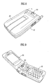
- Fig. 8 illustrates a perspective view of the portable telephone with a camera having a folder closed according to the present invention.
- Fig. 9 shows a perspective view of the portable telephone with a camera having a folder open according to the present invention.
- a portable telephone includes a main body 10, a folder 20 coupled with the upper main body 20, and a rotatable camera module 30 mounted on the main body 10.
- a front end of main body 10 has a control panel (buttons and function keys) placed on.
- a rotation-support part rotatably coupled to a camera module 30.
- a speaker and a display panel such as LCD are installed in an upper end of main body 10.
- a connecting part 26 is rotatably coupled to the rotation-support part 14.
- rotational axis 32 inserted into both sides of the camera module 30.
- it is desirable for rotation-support parts 14, a connecting part 26 and a rotation axis 32 of camera module 30 being installed as a pair.
- the folder 20 is coupled outside of the rotation-support part 14 on the main body 10.
- the camera module 30 is coupled inside of the rotation-support part 14 rotating separated from the folder 20 to outside of the rotation-support part 14.
- the lower end of the folder 20 has a pair of connecting parts 26. Inside of a pair of the connecting parts 26, an air gap 24 is placed as desirable. In at least one of a pair of connecting parts 26, a hinge element 26a is installed to have an easy access on folding and unfolding the folder. And also the other air gap 24 of connecting part 26 becomes a space for cables from a circuitry. In short, the air gap 24 is used as a space for flexible cables 52 of data signal to be connected between the display panel and the main body 10.
- camera module 30 there are an image sensor 34 receiving image signals, flexible cables transmitting image signals to a main board of the main body 10 in the image sensor. And also there is a transparent window 36 installed on a surface of the camera module 30.
- the camera module 30 has a cylindrical shape coordinated to rotate in full 360 degrees angle. It is desirable that at least one of rotation axes 32 could be made as an axis of an air gap placed on both sides of the camera module. Through the axis of an air gap, flexible cables 54 are connected from image sensor 34 to main board of the body 10.
- the rotation-support part 14 is placed either in parallel with or in a certain angle with respect to body 10. In other words, a rotation axis of the rotation-support part 14 is located upward or downward with respect to a front side of the main body 10. Outside of the rotation-support part 14, there is a hole for the connecting part 16.
- the hole for the connecting part 16 is a place wherein a rotation axis of the hinge element 26a is rotatably coupled.
- an air gap of inside of rotation-support part 14 placing some widths of W1 and W2 is used as a space to connect flexible cables 52, 54 with a main board of the main body 10.
- camera module 30 it is desirable for camera module 30 not to be too loose to rotate itself.
- the camera module should be fixed firmly in any desired angle after users rotate it. Eventually, it is necessary to locate a camera module 30 being rotated in any aiming angle and fixed subsequently by users, which is a role of method of lock-in position.
- a method of lock-in position can be described as below.
- the method of lock-in position is installed in the location between the rotation-support part 14 of the main body 10 and the camera module 30.
- the method of lock-in position includes an elastic sub-part 44 producing an elasticity (latitudinal sustainability) transformed by a rotation of the camera module 30, and a bushing 42 transforming the elastic sub-part 44 with fixed on inside of the rotation-support parts 14 of the main body 10.
- a bushing 42 consists of a roughly plate shape of contacting part 41 and a boss 43 formed to a single body with the contacting part 41.
- the rotation-support part 14 is formed by a subsided connecting part 41a and the contacting part 41 of the bushing 42 settles down in the connecting part 41a. Then, the boss 43 is inserted and assembled in a hole for the camera module 18. It is necessary that a rotation of the bushing 42 should not interfere with a rotational movement of the camera module 30.
- the bushing 42 could be fixed on the rotation-support part by using an adhesive, however the consideration of a convenient assembly should be taken into account.
- the contacting part 41 of bushing 42 is a non-circular shape.
- both sides of the contacting part 41 of bushing 42 are cut open and connecting part 41a of the rotation-support part 14 is supposed to have such a shape that matches with a shape of cut-open bushing 42.
- an elastic sub-part 44 is desirable to have a rough circular-plate shape formed by a protrusion 44a toward the bushing 42.
- the camera module cannot be rotated by itself due to the fact that the protrusion 44a of the elastic sub-part 44 compressed and transformed by bushing 22 producing an elasticity aside.
- the camera module 30 is incapable of being fixed in a designated position defined by users. Therefore, it is desirable for the bushing 42 to form a few grooves matched to the protrusion 44a on the side of touching the elastic sub-part in a contacting part 41. Once a few grooves are formed described above, the camera module 30 can be fixed firmly in the desired rotational angle where the protrusion 44a of the elastic sub-part 44 are fit into the grooves.
- the elastic sub-part 44 should rotate in a single body with the camera module 30. So the elastic sub-part 44 can be fixed on the camera module 30 by using adhesives, but the consideration of a convenience in assembly should also be taken into account. That is, the elastic sub-part 44 should be a non-circular shape. For example, as described in Fig 7, both sides of the elastic sub-part are cut open with some parts C. Then, one side of the camera module 30 is formed by a first concave part matching a shape of the elastic sub-part 44 to be fit in. Once this process is done, the elastic sub-part 44 can rotate in a single body with the camera module. Furthermore, some parts of the concave part 32a become much subsided, so that a second concave part 32b is formed being capable of transforming the elastic sub-part 44.
- the procedure of a described method of lock-in position is as follows. Once the protrusion 44a of an elastic sub-part 44 are initially fit into the grooves of bushing 42, the camera module 30 is on a mode of a fixed rotational angular position. Afterwards, users might need to adjust a camera-aiming angle of shooting an object by rotating it. With this action, it makes the elastic sub-part and the camera module rotate in a single body simultaneously. As a result, the protrusion 44a of the elastic sub-part 44 results comes off from the grooves in the bushing 42. And then, the protrusion 44a of the elastic sub-part 44 are moved on the flat plane area where there are no grooves on the bushing 42, so that the protrusion 44a are compressed.
- the second concave part 32b, formed on the side of the camera module 30, plays a role in keeping no resistance against the transformation of the elastic sub-part 44.
- the protrusion 44a get fit into next adjacent grooves via flat plane area. This results in locking in a next desired rotational angular position.
- camera module 30 does not rotate by itself due to being locked in a desired rotational angular position, when the protrusion 44a of the elastic sub-part gets fit into the grooves 42a of the bushing 42.
- a corresponding number of grooves 42a it is desirable to have a corresponding number of grooves 42a to be formed.
- a pair of the protrusions 44a on the elastic sub-part 44 are formed in a symmetrical pattern described in Fig. 7.
- the grooves 42a formed on the bushing 42 should have a corresponding number of pairs to match with the protrusion 44a.
- rotational angular movements between adjacent grooves can be varied for locking in rotational positions of the camera module 30.
- Fig. 6 and Fig. 7 show one example of designing camera module. That is, a pair of the protrusions 44a are formed in the elastic sub-part 44 and three pairs of grooves are formed in the bushing 42. Besides, an angle theta 1 between a reference groove and the next adjacent one in counterclockwise is approx. 30 degrees and an angle theta 2 between the reference and the next adjacent one in a clockwise is approx. 120 degrees. Therefore, a user can flip the folder and set the camera module 30 fixed on a first rotational position after rotating it in a 30 degree counterclockwise. In a clockwise direction, camera module 30 can be fixed on a first rotational position after being rotated in 120 degrees. A rotational angle of adjacent grooves on the bushing is varies by the number of grooves formed on it. Practically they can be modified for a design consideration.
- Fig. 8 and Fig. 9 illustrates a portable telephone with a camera by this present invention.
- a camera module has full 360 degree rotational movements relatively with respect to a main body, users can shoot an object in any angular position by rotating the camera module itself, instead of turning a whole body of a portable telephone on an image calling or a regular picture-taking mode. Eventually, an image calling by this portable telephone becomes more handy and particularly in taking a picture.
- the camera module aimed toward an object to be shot, can be rotated over the below of the flipped folder (the camera lens is facing out of a back side of the main body), a display panel on a front side can also be used as a viewfinder of camera such as a conventional digital camera.
- the camera module is located between rotation-support parts of the main body. Precisely, both a left and a right side of the camera module, supported by the main body are more protective than others. Consequently the usage of this portable phone with camera is very durable and reliable against external impacts.
- the camera module can be rotated in such an angle that the lens cannot be exposed from outside when users are carrying it or not using it. So this portable telephone has an advantage of resistances of damaged and contaminated on the camera lens, since it can be faced down into the main body. Therefore, it also prevents a picture quality from contaminated due to damage or scratch of a window of the camera module.
Landscapes
- Engineering & Computer Science (AREA)
- Signal Processing (AREA)
- Multimedia (AREA)
- Human Computer Interaction (AREA)
- Computer Networks & Wireless Communication (AREA)
- Telephone Set Structure (AREA)
- Studio Devices (AREA)
- Telephone Function (AREA)
Abstract
Description
- The present invention relates to a portable telephone with a built-in camera, and more particularly, to a portable telephone with a camera having a rotatable lens which enables users to aim an object in a desired rotational angle as wide as possible.
- In general, Portable telephones include cellular phones or Personal Communication Systems (PCS) having wireless communication capabilities. Nowadays as the need of video/image communication emerges, as well as voice communication, a portable telephone with a camera can be suggested to satisfy this demand.
- By considering Fig 1, a conventional portable telephone with a camera can be described as follows. Inside of a
main body 1 of the portable telephone, acamera 3 is mounted on the fixed location of an upper body. This type of portable telephone with a camera is unable to aim an object with any various angles without rotating a whole body, since the camera lens is formed into an embody of a portable telephone. For instance, since the camera lens is always facing out in the same direction of a LCD from themain body 1, users cannot aim a lens toward an object on the other side while they're looking at the LCD. Therefore in order to shoot an object on the other side (in the opposite direction of a LCD face), themain body 1 of a portable telephone needs to be turned around. Afterwards, users cannot check an aiming position of the camera lens, since not being able to look at the LCD on the main body. In short, by facing the main body out of users' side, they're unable to look at the image of pictures through the LCD panel such as a viewfinder of a camera. And also once it is turned around, it is hard to use function keys on a control panel. This leads to one of drawbacks. - Fig. 2 illustrates another example of conventional portable telephones with a camera. In an upper end of a
main body 1 of this portable telephone, acamera lens 3a is installed separated from themain body 1. In this case, this camera can only rotate with limited angles, for instance rotating up and down in a sense. This type of portable telephone with a camera gives a limitation such that it rotates in narrow angles. Since even the camera lens is exposed and sticks out on the edge of themain body 1, it is quite easy to be damaged and contaminated. - Fig. 3 illustrates another example of conventional portable telephones. In Fig. 3, a camera is mounted on an upper end of a main body. This camera rotates only on a horizontal axis. In this case, not being capable of rotating on a vertical axis (front to back of the main body 1), the horizontal rotational movement of camera doesn't give enough angles to shoot an object in a desired position. Unfortunately this type of camera on a portable telephone could not solve the problem in the previous example, such as easily damaged and contaminated of a camera lens
- . US 5 491 507 discloses a conventional portable phone with a camera mounted on the casing so as to be capable of altering its angle.
- Accordingly, the present invention is directed to a portable telephone with camera that substantially obviates one or more problems due to limitations and disadvantages of the related art above.
- An object of the present invention is to provide a portable telephone with a camera having a wide rotational angle of shooting an object in a front to back side of the portable telephone.
- Another object of the present invention is to provide a portable telephone with camera whose installation is more protective from the damage and contamination.
- In order to achieve the purpose of this invention mentioned above, a portable telephone with a camera includes a main body having a control panel installed on a front face of the main body and a rotation-support part formed in an upper end of the main body, a folder having a display panel and a speaker installed on a front face of the folder and having a connecting part formed in a low end of the folder, the connecting part being rotatably coupled to outer sides of the rotation-support part, and a camera module being rotatably coupled to inner sides of the rotation-support part.
- Also, a rotation axis of the camera module is not placed on a rotational axis of the folder, the rotational axes not overlapping each other.
- A hole for the folder, fitting a connecting part of the folder, is formed outside of the rotation-support part and A hole for fitting the camera module is formed inside of the rotation-support part for rotational movements. Herein, inside of the rotation-support part and the connecting part are formed by air gap wherein flexible cables are installed. In addition, the camera module is formed as a cylindrical shape having 360-degree rotational movements. Both sides of the camera module are formed by a rotation axis, desirable, having at least one of those rotation axes an air gap.
- According to an implementation of the present invention, a method of lock-in position is installed, between the camera module and the rotation-support part, fixing the camera module in a desired position. The method of lock-in position installed on one side of the camera module comprises an elastic sub-part producing an elasticity caused by being rotated simultaneously with the camera module; and a bushing fixed inside of the rotation-support part producing a strength to transform the elasticity when the camera module rotating.
- A surface of the elastic sub-part has a shape of plate formed by a protrusion. And one side of the elastic sub-part is cut open in order to rotate with an embodied of the camera module. A circumference of the elastic sub-part is partially cut open for being rotated as an embodied with the camera module and one side of the camera module is formed by a first concave part fitting the elastic sub-part, the first concave part matched with a shape of the elastic sub-part. And also some area of the first concave is subsided more, desirably to form second concave part.
- On the other hand, the bushing consists of: a contacting part of a plate and a boss as an embodied of the contacting part, the rotation-support part formed by a subsided connecting part, a contacting part of the bushing settled down in the connecting part, and the boss fit in a hole for the camera module. In addition, a contacting part of the bushing is desirable to form grooves fitting to the protrusion of the elastic sub-parts. And in order for the bushing to be fixed on the rotation support parts, both sides of the contacting part is cut open and a connecting part of the rotation-support part is supposed to be formed as roughly identical shape as the contacting part. Therefore according to the present invention, a camera module of this portable telephone can be rotated freely and set depending on the location of an object. And also it could prevent a camera lens from damage or contamination besides a wide rotational angle of the camera module.
- It is to be understood that both the foregoing general description and the following detailed description of the present invention are exemplary and explanatory and are intended to provide further explanation of the invention as claimed.
- The accompanying drawings, which are included to provide a further understanding of the invention and are incorporated in and constitute a part of this application, illustrate embodiment(s) of the invention and together with the description serve to explain the principle of the invention. In the drawings;
- Fig. 1 to Fig. 3 illustrate front views of conventional portable telephones with a camera;
- Fig. 4 illustrates an explored perspective view of a portable telephone with a camera according to the present invention as a rough drawing;
- Fig. 5 illustrates a cross-sectional view of the portable telephone shown in Fig. 4;
- Fig. 6 illustrates an exploded perspective of the camera module shown in Fig. 4;
- Fig. 7 illustrates a front view of a bushing shown in Fig 6.
- Fig. 8 illustrates a perspective view of the portable telephone with a camera having a folder closed according to the present invention; and
- Fig. 9 shows a perspective view of the portable telephone with a camera having a folder open according to the present invention.
- Reference will now be made in detail to the preferred embodiments of the present invention, examples of which are illustrated in the accompanying drawings. Wherever possible, the same reference numbers will be used throughout the drawings to refer to the same or like parts.
- In the below this portable telephone with a camera is described to meet the objectives by using appropriate examples in attached figures. By considering Fig. 4 to Fig. 6, a portable telephone according to the present invention includes a
main body 10, afolder 20 coupled with the uppermain body 20, and arotatable camera module 30 mounted on themain body 10. In Fig. 4, a front end ofmain body 10 has a control panel (buttons and function keys) placed on. In an upper end ofmain body 10, there is a rotation-support part rotatably coupled to acamera module 30. In a front end of thefolder 20, a speaker and a display panel such as LCD are installed. In a lower end of thefolder 20, a connectingpart 26 is rotatably coupled to the rotation-support part 14. And there is arotational axis 32 inserted into both sides of thecamera module 30. Herein, it is desirable for rotation-support parts 14, a connectingpart 26 and arotation axis 32 ofcamera module 30 being installed as a pair. - On the other hand, the
folder 20 is coupled outside of the rotation-support part 14 on themain body 10. Thecamera module 30 is coupled inside of the rotation-support part 14 rotating separated from thefolder 20 to outside of the rotation-support part 14. As seen in Fig. 5, it is desirable forfolder 20 andcamera module 30 to have two different alignments of rotation axes. The reason is that the general application of thefolder 20 versus a camera module might need different rotational angle. Therefore, it is necessary that thefolder 20 and thecamera module 30 can rotate separately with respect to amain body 20. Since thecamera module 30 can rotate in 360 degrees angle on a rotational axis of the rotation-support part 14, users can aim thecamera module 30 in any desired angle to an object being shot. - Now, the details regarding an assembly structure of a
main body 10, afolder 20, and acamera module 30 are explained explicitly as below. First of all, as described above, the lower end of thefolder 20 has a pair of connectingparts 26. Inside of a pair of the connectingparts 26, anair gap 24 is placed as desirable. In at least one of a pair of connectingparts 26, ahinge element 26a is installed to have an easy access on folding and unfolding the folder. And also theother air gap 24 of connectingpart 26 becomes a space for cables from a circuitry. In short, theair gap 24 is used as a space forflexible cables 52 of data signal to be connected between the display panel and themain body 10. - In
camera module 30, there are animage sensor 34 receiving image signals, flexible cables transmitting image signals to a main board of themain body 10 in the image sensor. And also there is atransparent window 36 installed on a surface of thecamera module 30. Thecamera module 30 has a cylindrical shape coordinated to rotate in full 360 degrees angle. It is desirable that at least one of rotation axes 32 could be made as an axis of an air gap placed on both sides of the camera module. Through the axis of an air gap,flexible cables 54 are connected fromimage sensor 34 to main board of thebody 10. - As described above regarding the
main body 10, there is a pair of the rotation-support parts. The rotation-support part 14 is placed either in parallel with or in a certain angle with respect tobody 10. In other words, a rotation axis of the rotation-support part 14 is located upward or downward with respect to a front side of themain body 10. Outside of the rotation-support part 14, there is a hole for the connectingpart 16. The hole for the connectingpart 16 is a place wherein a rotation axis of thehinge element 26a is rotatably coupled. Inside of the rotation-support parts 14, there is a hole for thecamera module 18 wherein a rotation axis of thecamera module 30 placed and assembled. In addition, an air gap of inside of rotation-support part 14 placing some widths of W1 and W2 is used as a space to connectflexible cables main body 10. - On the other hand, it is desirable for
camera module 30 not to be too loose to rotate itself. The camera module should be fixed firmly in any desired angle after users rotate it. Eventually, it is necessary to locate acamera module 30 being rotated in any aiming angle and fixed subsequently by users, which is a role of method of lock-in position. - A method of lock-in position can be described as below. The method of lock-in position is installed in the location between the rotation-
support part 14 of themain body 10 and thecamera module 30. The method of lock-in position includes anelastic sub-part 44 producing an elasticity (latitudinal sustainability) transformed by a rotation of thecamera module 30, and abushing 42 transforming theelastic sub-part 44 with fixed on inside of the rotation-support parts 14 of themain body 10. - More details are explained as follows. A
bushing 42 consists of a roughly plate shape of contactingpart 41 and aboss 43 formed to a single body with the contactingpart 41. The rotation-support part 14 is formed by a subsided connectingpart 41a and the contactingpart 41 of thebushing 42 settles down in the connectingpart 41a. Then, theboss 43 is inserted and assembled in a hole for thecamera module 18. It is necessary that a rotation of thebushing 42 should not interfere with a rotational movement of thecamera module 30. Definitely, thebushing 42 could be fixed on the rotation-support part by using an adhesive, however the consideration of a convenient assembly should be taken into account. In order to overcome this hindrance, it is necessary for the contactingpart 41 ofbushing 42 to be a non-circular shape. For instance, both sides of the contactingpart 41 ofbushing 42 are cut open and connectingpart 41a of the rotation-support part 14 is supposed to have such a shape that matches with a shape of cut-open bushing 42. - On the other hand, an
elastic sub-part 44 is desirable to have a rough circular-plate shape formed by aprotrusion 44a toward thebushing 42. With this set-up, the camera module cannot be rotated by itself due to the fact that theprotrusion 44a of theelastic sub-part 44 compressed and transformed by bushing 22 producing an elasticity aside. However, even if it can prevent the camera module from rotating by itself, thecamera module 30 is incapable of being fixed in a designated position defined by users. Therefore, it is desirable for thebushing 42 to form a few grooves matched to theprotrusion 44a on the side of touching the elastic sub-part in a contactingpart 41. Once a few grooves are formed described above, thecamera module 30 can be fixed firmly in the desired rotational angle where theprotrusion 44a of theelastic sub-part 44 are fit into the grooves. - Whereas, the
elastic sub-part 44 should rotate in a single body with thecamera module 30. So theelastic sub-part 44 can be fixed on thecamera module 30 by using adhesives, but the consideration of a convenience in assembly should also be taken into account. That is, theelastic sub-part 44 should be a non-circular shape. For example, as described in Fig 7, both sides of the elastic sub-part are cut open with some parts C. Then, one side of thecamera module 30 is formed by a first concave part matching a shape of theelastic sub-part 44 to be fit in. Once this process is done, theelastic sub-part 44 can rotate in a single body with the camera module. Furthermore, some parts of theconcave part 32a become much subsided, so that a secondconcave part 32b is formed being capable of transforming theelastic sub-part 44. - The procedure of a described method of lock-in position is as follows. Once the
protrusion 44a of anelastic sub-part 44 are initially fit into the grooves ofbushing 42, thecamera module 30 is on a mode of a fixed rotational angular position. Afterwards, users might need to adjust a camera-aiming angle of shooting an object by rotating it. With this action, it makes the elastic sub-part and the camera module rotate in a single body simultaneously. As a result, theprotrusion 44a of theelastic sub-part 44 results comes off from the grooves in thebushing 42. And then, theprotrusion 44a of theelastic sub-part 44 are moved on the flat plane area where there are no grooves on thebushing 42, so that theprotrusion 44a are compressed. As soon as they are compressed, an effect of transformation occurs. Then, the sustainability along a side can be generated as much as the transformation occurred. At this time, the secondconcave part 32b, formed on the side of thecamera module 30, plays a role in keeping no resistance against the transformation of theelastic sub-part 44. By rotatingcamera module 30 continuously, theprotrusion 44a get fit into next adjacent grooves via flat plane area. This results in locking in a next desired rotational angular position. As mentioned above,camera module 30 does not rotate by itself due to being locked in a desired rotational angular position, when theprotrusion 44a of the elastic sub-part gets fit into thegrooves 42a of thebushing 42. Considering rotational angular positions to be firmly locked in, it is desirable to have a corresponding number ofgrooves 42a to be formed. In addition, a pair of theprotrusions 44a on theelastic sub-part 44 are formed in a symmetrical pattern described in Fig. 7. And also, thegrooves 42a formed on thebushing 42 should have a corresponding number of pairs to match with theprotrusion 44a. And also, by spacing grooves on thebushing 44, rotational angular movements between adjacent grooves can be varied for locking in rotational positions of thecamera module 30. - Fig. 6 and Fig. 7 show one example of designing camera module. That is, a pair of the
protrusions 44a are formed in theelastic sub-part 44 and three pairs of grooves are formed in thebushing 42. Besides, anangle theta 1 between a reference groove and the next adjacent one in counterclockwise is approx. 30 degrees and anangle theta 2 between the reference and the next adjacent one in a clockwise is approx. 120 degrees. Therefore, a user can flip the folder and set thecamera module 30 fixed on a first rotational position after rotating it in a 30 degree counterclockwise. In a clockwise direction,camera module 30 can be fixed on a first rotational position after being rotated in 120 degrees. A rotational angle of adjacent grooves on the bushing is varies by the number of grooves formed on it. Practically they can be modified for a design consideration. - Fig. 8 and Fig. 9 illustrates a portable telephone with a camera by this present invention. First of all, according to this invention, since a camera module has full 360 degree rotational movements relatively with respect to a main body, users can shoot an object in any angular position by rotating the camera module itself, instead of turning a whole body of a portable telephone on an image calling or a regular picture-taking mode. Eventually, an image calling by this portable telephone becomes more handy and particularly in taking a picture. Since the camera module, aimed toward an object to be shot, can be rotated over the below of the flipped folder (the camera lens is facing out of a back side of the main body), a display panel on a front side can also be used as a viewfinder of camera such as a conventional digital camera. Therefore, users can watch how a picture can be being taken through a display panel when they try to shoot an object at the same time. And secondly, the camera module is located between rotation-support parts of the main body. Precisely, both a left and a right side of the camera module, supported by the main body are more protective than others. Consequently the usage of this portable phone with camera is very durable and reliable against external impacts. Thirdly, according to the present invention, the camera module can be rotated in such an angle that the lens cannot be exposed from outside when users are carrying it or not using it. So this portable telephone has an advantage of resistances of damaged and contaminated on the camera lens, since it can be faced down into the main body. Therefore, it also prevents a picture quality from contaminated due to damage or scratch of a window of the camera module.
- It will be apparent to those skilled in the art that various modifications and variations can be made in the present invention without departing from the spirit or scope of the inventions. Thus, it is intended that the present invention covers the modifications and variations of this invention provided they come within the scope of the appended claims and their equivalents.
Claims (14)
- A portable telephone with a camera comprising:a main body (10) having a control panel installed on a front face of said main body (10) and a rotation-support part (14) formed in an upper end of said main body (10);a folder (20) having a display panel (22) and a speaker (24) installed on a front face of said folder (20) and having a connecting part (26) formed in a low end of said folder (20), said connecting part (26) being rotatably coupled to said rotation-support part (14); anda camera module (30) being rotatably coupled to said rotation-support part (14);characterized in that
said connecting part (26) is coupled to outer sides of said rotation-support part (14); and said camera module (30) is coupled to inner sides of said rotation-support part (14); wherein said camera module (30) is arranged such that it is separately rotatable with respect to the folder (20) and the main body (10). - The portable telephone in claim 1, wherein means for fixing (42, 44) said camera module (30) in a desired rotational position are located between said camera module (30) and said rotation-support part (14).
- The portable telephone in claim 1, wherein a rotational axis (32) of said camera module (30) is inserted not being aligned with a rotating axis of said folder (20).
- The portable telephone in claim 1, wherein a hole (16) for said folder (20), fitting a connecting part (26) of said folder (20), is formed outside of said rotation-support part (14) and a hole (18) for fitting said camera module(30) is formed inside of said rotation-support part (14) for rotational movements.
- The portable telephone in claim 4, wherein inside of said rotation-support part (14) is formed with an air gap providing a space for flexible signal cables to be installed.
- The portable telephone in claim 4, wherein inside of said connecting part (26) is formed with an air gap (24) which provides a space for flexible signal cables to be installed.
- The portable telephone in claim 4, wherein said camera module (30) made as a roughly cylindrical shape is capable of being rotated in full 360 degrees and at least one of rotational axes (32) installed on both sides of said camera module (30) is formed with air gap inside.
- The portable telephone in claim 2, wherein said means for fixing (42, 44) installed on one side of said camera module (30) comprises:an elastic sub-part (44) producing an elasticity caused by being rotated simultaneously with said camera module (30); anda bushing (42) fixed inside of said rotation-support part (14) producing a strength to transform said elasticity when said camera module (30) rotating.
- The portable telephone in claim 8, wherein said elastic sub-part (44) has a shape of a plate and one side of said elastic sub-par (44)t has a protrusion (44a).
- The portable telephone in claim 9, wherein a circumference of said elastic sub-part (44) is partially cut open for being rotated as an embodied with said camera module (30) and one side of said camera module (30) is formed by a first concave part (32a) fitting said elastic sub-part (44), said first concave part (32a) matched with a shape of said elastic sub-part (44).
- The portable telephone in claim 10, wherein some portion of said first concave part (32a) is subsided resulting in a formation of a second concave part (32b).
- The portable telephone in claim 9, wherein said bushing (42) comprises a contacting part (41) having roughly a shape of a plate and a boss (43) as an embodied of said contacting part (41), said rotation-support part (14) formed by a subsided connecting part, the contacting part (41) of said bushing settled down in said connecting part, and said boss (43) fit in a hole for said camera module (30).
- The portable telephone in claim 12, wherein said contacting part (41) of said bushing (42) is formed by grooves (42a) matched with the protrusion (44a) on said elastic sub-part (44).
- The portable telephone in claim 13, wherein a circumference of said contacting part (41) of said bushing (42) is partially cut open and said connecting part (26) of said rotation-support part (14) is almost identical to a shape of said contacting part (41), for having said bushing (42) fixed on said rotation-support part (14).
Applications Claiming Priority (2)
| Application Number | Priority Date | Filing Date | Title |
|---|---|---|---|
| KR2001032865 | 2001-06-12 | ||
| KR10-2001-0032865A KR100539527B1 (en) | 2001-06-12 | 2001-06-12 | Portable Telephone with Camera |
Publications (3)
| Publication Number | Publication Date |
|---|---|
| EP1267576A2 EP1267576A2 (en) | 2002-12-18 |
| EP1267576A3 EP1267576A3 (en) | 2004-01-28 |
| EP1267576B1 true EP1267576B1 (en) | 2007-04-25 |
Family
ID=19710703
Family Applications (1)
| Application Number | Title | Priority Date | Filing Date |
|---|---|---|---|
| EP02012941A Expired - Lifetime EP1267576B1 (en) | 2001-06-12 | 2002-06-11 | Portable phone with camera |
Country Status (9)
| Country | Link |
|---|---|
| US (2) | US7133691B2 (en) |
| EP (1) | EP1267576B1 (en) |
| JP (2) | JP2003060764A (en) |
| KR (1) | KR100539527B1 (en) |
| CN (1) | CN1197414C (en) |
| AT (1) | ATE360957T1 (en) |
| DE (1) | DE60219716T2 (en) |
| ES (1) | ES2286176T3 (en) |
| PT (1) | PT1267576E (en) |
Cited By (3)
| Publication number | Priority date | Publication date | Assignee | Title |
|---|---|---|---|---|
| US8913172B2 (en) | 2008-06-13 | 2014-12-16 | Nintendo Co., Ltd. | Information processing apparatus and computer-readable storage medium recording information processing program |
| US9135026B2 (en) | 2008-06-13 | 2015-09-15 | Nintendo Co., Ltd. | Information-processing apparatus having photography applications |
| US9344706B2 (en) | 2007-08-29 | 2016-05-17 | Nintendo Co., Ltd. | Camera device |
Families Citing this family (192)
| Publication number | Priority date | Publication date | Assignee | Title |
|---|---|---|---|---|
| KR100274623B1 (en) | 1997-12-23 | 2000-12-15 | 윤종용 | Digital still camera |
| KR100539527B1 (en) * | 2001-06-12 | 2005-12-29 | 엘지전자 주식회사 | Portable Telephone with Camera |
| USD475358S1 (en) | 2001-07-27 | 2003-06-03 | Motorola, Inc. | Housing for a communication device |
| KR100429979B1 (en) * | 2001-09-26 | 2004-05-03 | 엘지전자 주식회사 | Potable image phone |
| KR100454965B1 (en) * | 2001-12-29 | 2004-11-06 | 삼성전자주식회사 | Portable phone with camera lenz opening means in closed folder |
| USD487453S1 (en) | 2002-02-05 | 2004-03-09 | Motorola, Inc. | Housing accessory for communication devices or similar articles |
| USD477581S1 (en) | 2002-03-12 | 2003-07-22 | Matsushita Electric Industrial Co., Ltd. | Mobile phone with a camera |
| USD476968S1 (en) | 2002-03-15 | 2003-07-08 | Kabushiki Kaisha Toshiba | Portable phone |
| USD479522S1 (en) | 2002-03-19 | 2003-09-09 | Kyocera Corporation | Portable telephone |
| KR100465226B1 (en) * | 2002-03-28 | 2005-01-13 | 주식회사 엠투시스 | Cover hinge mechanism of cellular phone |
| USD477296S1 (en) | 2002-04-22 | 2003-07-15 | Kyocera Corporation | Portable telephone with camera |
| KR100459543B1 (en) * | 2002-07-10 | 2004-12-03 | 삼성전자주식회사 | Camera lens module and portable wireless terminal therewith |
| US7773957B2 (en) * | 2002-07-22 | 2010-08-10 | Samsung Electronics Co., Ltd | Mobile communication terminal with rotational display unit |
| USD512053S1 (en) * | 2002-09-17 | 2005-11-29 | Kyoćera Wireless Corp. | Wireless communication device |
| USD484478S1 (en) | 2002-09-19 | 2003-12-30 | Hitachi, Ltd. | Mobile telephone |
| JP3675430B2 (en) * | 2002-09-20 | 2005-07-27 | 株式会社日立製作所 | Mobile phone |
| USD489345S1 (en) | 2002-09-26 | 2004-05-04 | Nec Corporation | Portable wireless telephone |
| USD489362S1 (en) | 2002-09-26 | 2004-05-04 | Nec Corporation | Keypad for a portable wireless telephone |
| KR100455776B1 (en) * | 2002-11-18 | 2004-11-06 | 엘지전자 주식회사 | A mobile telecommunication terminal having a camera |
| KR100487616B1 (en) * | 2002-11-29 | 2005-05-03 | 엘지전자 주식회사 | Folder type mobile phone |
| JP4233855B2 (en) * | 2002-11-29 | 2009-03-04 | 京セラ株式会社 | Mobile terminal device |
| USD484862S1 (en) | 2002-12-03 | 2004-01-06 | Curitel Communications, Inc. | Cellular phone |
| USD490389S1 (en) | 2002-12-03 | 2004-05-25 | Curitel Communications, Inc. | Cellular phone |
| JP2004214946A (en) | 2002-12-27 | 2004-07-29 | Casio Comput Co Ltd | Foldable portable information device |
| KR20040060378A (en) * | 2002-12-30 | 2004-07-06 | 엘지전자 주식회사 | Cammera case structure of mobile phone |
| JP3950062B2 (en) * | 2003-01-10 | 2007-07-25 | ソニー・エリクソン・モバイルコミュニケーションズ株式会社 | Information terminal equipment |
| KR101012582B1 (en) * | 2003-01-10 | 2011-02-07 | 소니 에릭슨 모빌 커뮤니케이션즈 재팬, 아이엔씨. | Information terminal equipment |
| TW572503U (en) * | 2003-01-20 | 2004-01-11 | Benq Corp | Electronic device with display screen and image sensor |
| USD493436S1 (en) | 2003-01-21 | 2004-07-27 | Matsushita Electric Industrial Co., Ltd. | Mobile phone |
| USD493437S1 (en) | 2003-01-31 | 2004-07-27 | Matsushita Electric Industrial Co., Ltd. | Mobile phone |
| KR100547712B1 (en) | 2003-02-28 | 2006-01-31 | 삼성전자주식회사 | How to lock and unlock the camera on a portable device with a camera |
| USD503695S1 (en) * | 2003-03-14 | 2005-04-05 | Hitachi, Ltd. | Mobile telephone |
| KR100959729B1 (en) * | 2003-03-15 | 2010-05-25 | 엘지전자 주식회사 | Clamshell terminal |
| CN1305336C (en) * | 2003-03-19 | 2007-03-14 | 三星电子株式会社 | Camera lens in portable radio terminal |
| KR100601492B1 (en) * | 2003-03-29 | 2006-07-14 | 삼성전기주식회사 | Camera Rotation Drive Module by Motor and Sensor |
| CN100352245C (en) * | 2003-04-05 | 2007-11-28 | 鸿富锦精密工业(深圳)有限公司 | Handset |
| JP4188867B2 (en) * | 2003-04-14 | 2008-12-03 | 三星電子株式会社 | Portable terminal equipped with a rotating camera lens housing |
| KR100526555B1 (en) * | 2003-04-15 | 2005-11-03 | 삼성전자주식회사 | Portable wireless terminal |
| KR100524747B1 (en) * | 2003-04-16 | 2005-11-01 | 엘지전자 주식회사 | Driver device of camera assembly for mobile image phone and control method thereof |
| USD484479S1 (en) | 2003-04-16 | 2003-12-30 | Curitel Communications, Inc. | Cellular phone |
| KR100548343B1 (en) * | 2003-05-12 | 2006-02-02 | 엘지전자 주식회사 | Camera Fixer in Mobile Phone |
| KR100565269B1 (en) * | 2003-05-15 | 2006-03-30 | 엘지전자 주식회사 | Shooting method of mobile communication terminal with camera function |
| KR100518002B1 (en) * | 2003-05-30 | 2005-09-30 | 엘지전자 주식회사 | Camera angle control apparatus of mobile phone |
| USD493439S1 (en) | 2003-06-11 | 2004-07-27 | Benq Corporation | Mobile phone |
| USD487444S1 (en) | 2003-06-12 | 2004-03-09 | Curitel Communications, Inc. | Cellular phone |
| USD496017S1 (en) | 2003-06-12 | 2004-09-14 | Motorola, Inc. | Housing for a radio telephone or similar article |
| USD487443S1 (en) | 2003-06-12 | 2004-03-09 | Curitel Communications, Inc. | Cellular phone |
| USD487736S1 (en) | 2003-06-17 | 2004-03-23 | Matsushita Electric Industrial Co., Ltd. | Mobile phone |
| USD487071S1 (en) | 2003-06-17 | 2004-02-24 | Matsushita Electric Industrial Co., Ltd. | Mobile phone |
| USD488791S1 (en) | 2003-06-17 | 2004-04-20 | Matsushita Electric Industrial Co., Ltd. | Mobile phone |
| USD496643S1 (en) | 2003-07-04 | 2004-09-28 | Lg Electronics Inc. | Mobile phone |
| USD496644S1 (en) | 2003-07-04 | 2004-09-28 | Lg Electronics Inc. | Mobile phone |
| USD495674S1 (en) | 2003-07-04 | 2004-09-07 | Lg Electronics Inc. | Mobile phone |
| ATE422782T1 (en) | 2003-07-04 | 2009-02-15 | Lg Electronics Inc | ROTATABLE CAMERA FOR A MOBILE COMMUNICATIONS DEVICE |
| USD496645S1 (en) | 2003-07-04 | 2004-09-28 | Lg Electronics Inc. | Mobile phone |
| EP1496699B1 (en) * | 2003-07-08 | 2009-06-10 | Lg Electronics Inc. | Rotary camera assembly of mobile communication device |
| USD498734S1 (en) | 2003-07-23 | 2004-11-23 | Lg Electronics Inc. | Cellular phone |
| JP4260568B2 (en) * | 2003-07-31 | 2009-04-30 | 京セラ株式会社 | Camera apparatus and image processing control method |
| KR100561279B1 (en) * | 2003-08-09 | 2006-03-14 | 엘지전자 주식회사 | Camera Rotator of Mobile Communication Terminal |
| KR100575739B1 (en) * | 2003-09-30 | 2006-05-03 | 엘지전자 주식회사 | Hinge Device of Portable Terminal |
| KR100980548B1 (en) | 2003-10-11 | 2010-09-06 | 엘지전자 주식회사 | Camera rotation support device of portable terminal |
| CN100496060C (en) * | 2003-10-14 | 2009-06-03 | 明基电通股份有限公司 | Structure of Mobile Phone and Portable Electronic Device |
| JP4048435B2 (en) * | 2003-10-23 | 2008-02-20 | ソニー株式会社 | Electronics |
| KR100575746B1 (en) * | 2003-10-28 | 2006-05-03 | 엘지전자 주식회사 | Clamshell terminal |
| KR100576007B1 (en) * | 2003-11-03 | 2006-05-02 | 삼성전자주식회사 | Camera lens assembly in portable terminal |
| USD495672S1 (en) | 2003-11-10 | 2004-09-07 | Samsung Electronics Co., Ltd. | Cellular phone |
| KR100677300B1 (en) | 2003-11-21 | 2007-02-05 | 엘지전자 주식회사 | Handheld terminal |
| USD505126S1 (en) * | 2003-11-29 | 2005-05-17 | Samsung Electronics Co., Ltd. | Portable telephone |
| USD505125S1 (en) * | 2003-11-29 | 2005-05-17 | Samsung Electronics Co., Ltd. | Portable telephone |
| USD502459S1 (en) * | 2003-12-01 | 2005-03-01 | Samsung Electronics Co., Ltd. | Cellular phone |
| KR100584397B1 (en) * | 2003-12-03 | 2006-05-26 | 삼성전자주식회사 | Camera lens assembly in portable terminal |
| USD511336S1 (en) * | 2003-12-04 | 2005-11-08 | Samsung Electronics Co., Ltd. | Cellular phone |
| USD508032S1 (en) * | 2003-12-06 | 2005-08-02 | Samsung Electronics Co., Ltd. | Cellular phone |
| USD510922S1 (en) * | 2003-12-11 | 2005-10-25 | Samsung Electronics Co., Ltd. | Portable telephone |
| USD507252S1 (en) * | 2003-12-11 | 2005-07-12 | Samsung Electronics Co., Ltd. | Portable telephone |
| US7274746B2 (en) * | 2003-12-24 | 2007-09-25 | Spirent Communications Of Rockville, Inc. | System and method for mitigating noise associated with information communication |
| KR100595640B1 (en) * | 2003-12-26 | 2006-06-30 | 엘지전자 주식회사 | Folder dual rotation switchgear of portable terminal |
| KR20050066597A (en) * | 2003-12-26 | 2005-06-30 | 엘지전자 주식회사 | Folder type mobile phone with camera apparatus |
| EP1558007B1 (en) | 2004-01-20 | 2011-03-02 | Panasonic Corporation | Foldable portable terminal device with extendable camera module |
| USD516048S1 (en) * | 2004-02-18 | 2006-02-28 | Asia Optical Co., Inc. | Photographable flip-up mobile phone |
| KR100630098B1 (en) * | 2004-02-20 | 2006-09-27 | 삼성전자주식회사 | Portable digital communication device |
| KR100689386B1 (en) * | 2004-03-15 | 2007-03-02 | 삼성전자주식회사 | Camera lens module popup device of mobile terminal |
| USD509814S1 (en) * | 2004-03-19 | 2005-09-20 | Lg Electronics, Inc. | Mobile phone |
| USD497894S1 (en) | 2004-03-22 | 2004-11-02 | Curitel Communications, Inc. | Combined cellular phone and camcorder |
| KR100662333B1 (en) * | 2004-03-30 | 2007-01-02 | 엘지전자 주식회사 | Mobile communication terminal |
| KR100757445B1 (en) * | 2004-03-31 | 2007-09-11 | 엘지전자 주식회사 | Handheld terminal |
| USD508036S1 (en) * | 2004-04-02 | 2005-08-02 | Sony Ericsson Mobile Communications Ab | Mobile phone |
| JP2007532071A (en) * | 2004-04-05 | 2007-11-08 | ノキア コーポレイション | Electronic imaging device |
| USD512395S1 (en) * | 2004-04-06 | 2005-12-06 | Samsung Electronics Co., Ltd. | Cellular phone |
| USD513244S1 (en) * | 2004-05-05 | 2005-12-27 | Samsung Electronics Co., Ltd. | Portable telephone |
| USD508685S1 (en) * | 2004-05-05 | 2005-08-23 | Samsung Electronics Co., Ltd. | Portable telephone |
| USD501838S1 (en) * | 2004-05-05 | 2005-02-15 | Samsung Electronics Co., Ltd. | Portable telephone |
| KR100703351B1 (en) * | 2004-05-06 | 2007-04-03 | 삼성전자주식회사 | Swing type mobile device |
| KR100617688B1 (en) * | 2004-05-19 | 2006-08-28 | 삼성전자주식회사 | Hinge device of a mobile terminal |
| USD511509S1 (en) * | 2004-06-07 | 2005-11-15 | Samsung Electronics Co., Ltd. | Cellular phone |
| JP4431447B2 (en) * | 2004-06-09 | 2010-03-17 | 富士フイルム株式会社 | Digital camera |
| US20050275751A1 (en) * | 2004-06-11 | 2005-12-15 | Sony Ericsson Mobile Communications Ab | Security cover |
| TWM264768U (en) * | 2004-06-18 | 2005-05-11 | Fih Co Ltd | Multi-segtion hinge mechanism |
| US20050282593A1 (en) * | 2004-06-21 | 2005-12-22 | Spence Michael F | Mechanical layout and component placement for thin clamshell phone |
| USD518807S1 (en) * | 2004-06-24 | 2006-04-11 | Samsung Electronics Co., Ltd. | Cellular phone |
| KR100677333B1 (en) * | 2004-07-06 | 2007-02-02 | 엘지전자 주식회사 | Camera assembly of portable terminal |
| CN101023464B (en) * | 2004-07-16 | 2011-06-01 | 基伯技术公司 | Handheld Electronic Devices |
| US20060035677A1 (en) * | 2004-08-11 | 2006-02-16 | Naveen Aerrabotu | Disablement of external keys in a communication device |
| CN100397965C (en) * | 2004-08-16 | 2008-06-25 | 明基电通股份有限公司 | Electronic device and image structure thereof |
| JP4224712B2 (en) * | 2004-09-24 | 2009-02-18 | 日本電気株式会社 | Foldable mobile phone device and method for assembling the same |
| US7869790B2 (en) * | 2004-09-24 | 2011-01-11 | Scenera Technologies, Llc | Policy-based controls for wireless cameras |
| USD510333S1 (en) * | 2004-10-28 | 2005-10-04 | Motorola, Inc. | Communication device |
| USD518812S1 (en) * | 2005-01-03 | 2006-04-11 | Samsung Electronics Co., Ltd. | Cellular phone |
| TWI250790B (en) | 2005-01-07 | 2006-03-01 | Asustek Comp Inc | Display device having rotational image-capturing module |
| US20060152576A1 (en) * | 2005-01-11 | 2006-07-13 | Agere Systems Incorporated | Mobile communication device having detachable wireless camera and camera module for a mobile communication device |
| USD542759S1 (en) * | 2005-01-26 | 2007-05-15 | Samsung Electronics Co., Ltd. | Portable phone |
| USD545795S1 (en) * | 2005-01-26 | 2007-07-03 | Samsung Electronics Co., Ltd. | Portable phone |
| EP1688821A1 (en) * | 2005-02-02 | 2006-08-09 | Huawei Technologies Co., Ltd. | Liquid crystal display screen with camera |
| US7528885B2 (en) * | 2005-02-07 | 2009-05-05 | Ensky Technology Co., Ltd. | Portable electronic device with lens rotation positioning structure |
| KR20060096209A (en) * | 2005-03-03 | 2006-09-11 | 주식회사 팬택앤큐리텔 | Camera rotation control device of mobile communication terminal |
| USD521968S1 (en) | 2005-03-03 | 2006-05-30 | Samsung Electronics Co., Ltd. | Portable telephone |
| KR100605842B1 (en) * | 2005-03-04 | 2006-08-01 | 삼성전자주식회사 | Camera Lens Module Rotating Device for Mobile Terminal |
| USD520982S1 (en) | 2005-03-29 | 2006-05-16 | Samsung Electronics Co., Ltd. | Portable telephone |
| USD521483S1 (en) | 2005-03-29 | 2006-05-23 | Samsung Electronics Co., Ltd. | Portable telephone |
| USD519098S1 (en) | 2005-03-29 | 2006-04-18 | Samsung Electronics Co., Ltd. | Portable telephone |
| USD520981S1 (en) | 2005-03-29 | 2006-05-16 | Samsung Electronics Co., Ltd. | Portable telephone |
| USD523411S1 (en) | 2005-03-29 | 2006-06-20 | Samsung Electronics Co., Ltd. | Portable telephone |
| USD528091S1 (en) | 2005-03-29 | 2006-09-12 | Samsung Electronics Co., Ltd. | Portable telephone |
| USD521971S1 (en) | 2005-03-29 | 2006-05-30 | Samsung Electronics Co., Ltd. | Portable telephone |
| USD521972S1 (en) | 2005-03-29 | 2006-05-30 | Samsung Electronics Co., Ltd. | Portable telephone |
| USD519486S1 (en) | 2005-03-29 | 2006-04-25 | Samsung Electronics Co., Ltd. | Portable telephone |
| USD521970S1 (en) | 2005-03-29 | 2006-05-30 | Samsung Electronics Co., Ltd. | Portable telephone |
| USD521969S1 (en) | 2005-03-29 | 2006-05-30 | Samsung Electronics Co., Ltd. | Portable telephone |
| USD523833S1 (en) | 2005-03-29 | 2006-06-27 | Samsung Electronics Co., Ltd. | Portable telephone |
| USD528528S1 (en) | 2005-03-29 | 2006-09-19 | Samsung Electronics Co., Ltd. | Portable telephone |
| USD522991S1 (en) | 2005-03-29 | 2006-06-13 | Samsung Electronics Co., Ltd. | Portable telephone |
| USD524276S1 (en) | 2005-03-29 | 2006-07-04 | Samsung Electronics Co., Ltd. | Portable telephone |
| USD529888S1 (en) | 2005-03-29 | 2006-10-10 | Samsung Electronics Co., Ltd. | Portable telephone |
| KR20080004546A (en) * | 2005-03-30 | 2008-01-09 | 코닌클리케 필립스 일렉트로닉스 엔.브이. | Portable Electronic Device with Rotating Camera Unit |
| USD540766S1 (en) | 2005-04-05 | 2007-04-17 | Samsung Electronics Co., Ltd. | Portable telephone |
| USD537427S1 (en) | 2005-04-05 | 2007-02-27 | Samsung Electronics Co., Ltd. | Portable telephone |
| USD535634S1 (en) | 2005-04-08 | 2007-01-23 | Samsung Electronics Co., Ltd. | Portable telephone |
| USD538248S1 (en) | 2005-04-08 | 2007-03-13 | Samsung Electronics Co., Ltd. | Portable telephone |
| USD542251S1 (en) | 2005-04-08 | 2007-05-08 | Samsung Electronics Co., Ltd. | Portable telephone |
| USD546307S1 (en) * | 2005-04-11 | 2007-07-10 | Samsung Electronics Co., Ltd. | Mobile phone |
| USD539253S1 (en) | 2005-06-02 | 2007-03-27 | Samsung Electronics Co., Ltd. | Portable telephone |
| USD539254S1 (en) | 2005-06-02 | 2007-03-27 | Samsung Electronics Co., Ltd. | Portable telephone |
| KR100703332B1 (en) * | 2005-06-07 | 2007-04-03 | 삼성전자주식회사 | How to change the operation mode of a mobile terminal |
| CN1697462A (en) * | 2005-06-24 | 2005-11-16 | 朱占新 | Bi-directional rolling screen type mobile communication terminal |
| US8145241B2 (en) | 2005-06-30 | 2012-03-27 | Armstrong, Quinton Co. LLC | Methods, systems, and computer program products for role- and locale-based mobile user device feature control |
| USD538250S1 (en) | 2005-08-02 | 2007-03-13 | Samsung Electronics Co., Ltd. | Portable telephone |
| USD546797S1 (en) | 2005-08-04 | 2007-07-17 | Samsung Electronics Co., Ltd. | Portable telephone |
| USD546798S1 (en) | 2005-08-04 | 2007-07-17 | Samsung Electronics Co., Ltd. | Portable telephone |
| US20070147817A1 (en) * | 2005-09-29 | 2007-06-28 | Jingqiang Li | Camera feature with divided autofocus search range |
| JP4479643B2 (en) * | 2005-10-28 | 2010-06-09 | ソニー株式会社 | Camera module and electronic equipment |
| US7428380B2 (en) * | 2005-11-16 | 2008-09-23 | Inventec Corporation | Portable electronic device |
| KR100683868B1 (en) * | 2005-12-05 | 2007-02-15 | 삼성전자주식회사 | Antenna applied to slide type mobile communication terminal |
| KR100716818B1 (en) * | 2005-12-29 | 2007-05-09 | 삼성전기주식회사 | Camera position sensing device and mobile phone including the same |
| US7512429B2 (en) * | 2006-01-11 | 2009-03-31 | Inventec Corporation | Erect mobile phone device |
| USD567205S1 (en) * | 2006-02-10 | 2008-04-22 | Samsung Electronics Co., Ltd. | Portable phone with removable wireless earpiece |
| USD573120S1 (en) * | 2006-03-17 | 2008-07-15 | Research In Motion Limited | Handheld device |
| USD565006S1 (en) * | 2006-03-17 | 2008-03-25 | Research In Motion Limited | Handheld device |
| USD569826S1 (en) * | 2006-03-17 | 2008-05-27 | Research In Motion Limited | Handheld device |
| USD558174S1 (en) * | 2006-03-22 | 2007-12-25 | Samsung Electronics Co., Ltd. | Cellular phone |
| TWM304172U (en) * | 2006-07-11 | 2007-01-01 | Quanta Comp Inc | Hand held apparatus and an active flip device for a foldable cover thereof |
| KR100810370B1 (en) * | 2006-07-24 | 2008-03-04 | 삼성전자주식회사 | Portable terminal with camera lens assembly |
| US20080058008A1 (en) * | 2006-08-02 | 2008-03-06 | Jae-Woong Yoon | Mobile telecommunication apparatus with a built-in camera and the camera therein |
| USD564484S1 (en) * | 2006-10-12 | 2008-03-18 | Kyocera Wireless Corp. | Mobile handset |
| USD583783S1 (en) * | 2006-10-17 | 2008-12-30 | Sprint Spectrum L.P. | Phone |
| KR100836616B1 (en) * | 2006-11-14 | 2008-06-10 | (주)케이티에프테크놀로지스 | Image Synthesis Method of Portable Terminal and Portable Terminal with Image Synthesis Function |
| USD563937S1 (en) * | 2006-12-20 | 2008-03-11 | Samsung Electronics Co., Ltd. | Portable phone |
| KR100777155B1 (en) * | 2006-12-27 | 2007-11-19 | 엘지전자 주식회사 | Mobile communication terminal with camera module |
| US8177441B2 (en) | 2007-08-29 | 2012-05-15 | Nintendo Co., Ltd. | Imaging apparatus |
| US8917985B2 (en) | 2007-08-29 | 2014-12-23 | Nintendo Co., Ltd. | Imaging apparatus |
| WO2010038296A1 (en) | 2008-10-01 | 2010-04-08 | 任天堂株式会社 | Information processing device, information processing system, boot program and storage medium storing same |
| US20100186234A1 (en) | 2009-01-28 | 2010-07-29 | Yehuda Binder | Electric shaver with imaging capability |
| US8477505B2 (en) * | 2009-09-29 | 2013-07-02 | Netgear, Inc. | Peripheral device with limited relative angular movement |
| CN102069672B (en) * | 2009-11-20 | 2013-12-25 | 深圳富泰宏精密工业有限公司 | Method for manufacturing decorative shell |
| KR101641151B1 (en) | 2009-12-10 | 2016-07-20 | 휴렛-팩커드 디벨롭먼트 컴퍼니, 엘.피. | Portable computer having a tilt camera assembly |
| USD624046S1 (en) * | 2010-03-04 | 2010-09-21 | Samsung Electronics Co., Ltd. | Cellular phone |
| US8988558B2 (en) * | 2011-04-26 | 2015-03-24 | Omnivision Technologies, Inc. | Image overlay in a mobile device |
| KR101278352B1 (en) * | 2011-11-07 | 2013-06-25 | 삼성전기주식회사 | Camera module |
| US20130120568A1 (en) * | 2011-11-15 | 2013-05-16 | II Michael E. Jensen | Security and Marketing System |
| CN104216509B (en) * | 2013-06-03 | 2017-09-29 | 联想(北京)有限公司 | A kind of electronic equipment and information processing method |
| CN104301660A (en) * | 2014-10-31 | 2015-01-21 | 四川量迅科技有限公司 | Portable image communication equipment |
| CN104320732A (en) * | 2014-11-19 | 2015-01-28 | 四川量迅科技有限公司 | Self-help multifunctional microphone |
| CN104853093B (en) * | 2015-04-30 | 2018-01-23 | 广东欧珀移动通信有限公司 | The control method and mobile terminal of a kind of rotatable camera |
| CN107071103A (en) * | 2017-03-28 | 2017-08-18 | 北京小米移动软件有限公司 | Mobile terminal |
| CN109981827B (en) * | 2017-12-28 | 2021-02-26 | Oppo广东移动通信有限公司 | Terminal equipment and its camera assembly |
| CN108934566A (en) * | 2018-07-13 | 2018-12-07 | 杭州智控网络有限公司 | A kind of planting machine of adjustable light compensating lamp position |
| CN108739346A (en) * | 2018-07-13 | 2018-11-06 | 杭州智控网络有限公司 | A kind of plant growing machine |
| CN109743423B (en) * | 2019-01-08 | 2022-06-07 | 合肥京东方光电科技有限公司 | Display device and control method thereof |
| US11546451B2 (en) | 2019-05-15 | 2023-01-03 | Asustek Computer Inc. | Electronic device |
| US11240357B2 (en) | 2019-05-15 | 2022-02-01 | Asustek Computer Inc. | Electronic device |
| US11375125B2 (en) | 2019-05-15 | 2022-06-28 | Asustek Computer Inc. | Electronic device |
| US11477385B2 (en) | 2019-05-15 | 2022-10-18 | Asustek Computer Inc. | Electronic device with rotatable camera for protecting privacy |
| US10911593B2 (en) * | 2019-05-15 | 2021-02-02 | Asustek Computer Inc. | Electronic device having a rotatable camera module |
Family Cites Families (15)
| Publication number | Priority date | Publication date | Assignee | Title |
|---|---|---|---|---|
| JPH0343733Y2 (en) * | 1986-03-17 | 1991-09-12 | ||
| US5259019A (en) * | 1991-04-08 | 1993-11-02 | Texas Instruments Incorporated | Apparatus providing for a curved device with hinged cover |
| JP3255995B2 (en) * | 1992-10-23 | 2002-02-12 | 株式会社日立製作所 | Videophone equipment |
| JPH08181465A (en) * | 1994-12-26 | 1996-07-12 | Kokusai Electric Co Ltd | Electronics unit |
| SG70987A1 (en) * | 1995-05-09 | 2000-03-21 | Motorola Inc | Method and apparatus for routing conductors |
| JP3612881B2 (en) * | 1996-09-03 | 2005-01-19 | ミノルタ株式会社 | Digital camera |
| JP2928184B2 (en) * | 1997-02-04 | 1999-08-03 | 埼玉日本電気株式会社 | Foldable portable wireless communication device |
| JPH1169213A (en) * | 1997-08-21 | 1999-03-09 | Nikon Corp | Camera with monitor device |
| JP3516328B2 (en) | 1997-08-22 | 2004-04-05 | 株式会社日立製作所 | Information communication terminal equipment |
| US6444393B2 (en) | 1998-03-26 | 2002-09-03 | Fuji Photo Film Co., Ltd. | Anionic infrared-ray absorbing agent, photosensitive composition and planographic printing plate precursor using same |
| JP2000253113A (en) | 1999-02-26 | 2000-09-14 | Hitachi Ltd | Information communication terminal equipment |
| JP2000253124A (en) | 1999-03-01 | 2000-09-14 | Matsushita Electric Ind Co Ltd | Information portable terminal with imaging function |
| JP2000295504A (en) * | 1999-04-06 | 2000-10-20 | Canon Inc | Digital camera |
| WO2000069158A1 (en) | 1999-05-06 | 2000-11-16 | Kyocera Corporation | Videophone system using cellular telephone terminal |
| KR100539527B1 (en) * | 2001-06-12 | 2005-12-29 | 엘지전자 주식회사 | Portable Telephone with Camera |
-
2001
- 2001-06-12 KR KR10-2001-0032865A patent/KR100539527B1/en not_active Expired - Fee Related
-
2002
- 2002-06-04 US US10/161,905 patent/US7133691B2/en not_active Expired - Lifetime
- 2002-06-11 AT AT02012941T patent/ATE360957T1/en active
- 2002-06-11 CN CNB021227691A patent/CN1197414C/en not_active Expired - Fee Related
- 2002-06-11 EP EP02012941A patent/EP1267576B1/en not_active Expired - Lifetime
- 2002-06-11 ES ES02012941T patent/ES2286176T3/en not_active Expired - Lifetime
- 2002-06-11 DE DE60219716T patent/DE60219716T2/en not_active Expired - Lifetime
- 2002-06-11 PT PT02012941T patent/PT1267576E/en unknown
- 2002-06-12 JP JP2002172099A patent/JP2003060764A/en active Pending
-
2005
- 2005-10-17 JP JP2005302313A patent/JP4243606B2/en not_active Expired - Fee Related
-
2006
- 2006-10-25 US US11/552,947 patent/US7627342B2/en not_active Expired - Fee Related
Non-Patent Citations (1)
| Title |
|---|
| None * |
Cited By (4)
| Publication number | Priority date | Publication date | Assignee | Title |
|---|---|---|---|---|
| US9344706B2 (en) | 2007-08-29 | 2016-05-17 | Nintendo Co., Ltd. | Camera device |
| US8913172B2 (en) | 2008-06-13 | 2014-12-16 | Nintendo Co., Ltd. | Information processing apparatus and computer-readable storage medium recording information processing program |
| US9135026B2 (en) | 2008-06-13 | 2015-09-15 | Nintendo Co., Ltd. | Information-processing apparatus having photography applications |
| US9256449B2 (en) | 2008-06-13 | 2016-02-09 | Nintendo Co., Ltd. | Menu screen for information processing apparatus and computer-readable storage medium recording information processing program |
Also Published As
| Publication number | Publication date |
|---|---|
| KR100539527B1 (en) | 2005-12-29 |
| CN1391420A (en) | 2003-01-15 |
| US20070132835A1 (en) | 2007-06-14 |
| JP2003060764A (en) | 2003-02-28 |
| EP1267576A2 (en) | 2002-12-18 |
| ES2286176T3 (en) | 2007-12-01 |
| DE60219716T2 (en) | 2008-01-17 |
| DE60219716D1 (en) | 2007-06-06 |
| PT1267576E (en) | 2007-05-31 |
| US7627342B2 (en) | 2009-12-01 |
| JP4243606B2 (en) | 2009-03-25 |
| US7133691B2 (en) | 2006-11-07 |
| CN1197414C (en) | 2005-04-13 |
| US20020187818A1 (en) | 2002-12-12 |
| JP2006042396A (en) | 2006-02-09 |
| EP1267576A3 (en) | 2004-01-28 |
| KR20020094587A (en) | 2002-12-18 |
| ATE360957T1 (en) | 2007-05-15 |
Similar Documents
| Publication | Publication Date | Title |
|---|---|---|
| US7133691B2 (en) | Portable phone with camera | |
| JP4286735B2 (en) | Portable device | |
| US6975273B1 (en) | Antenna with camera lens assembly for portable radiotelephone | |
| US6882726B2 (en) | Apparatus for mounting a rotational lens housing in a folder-type telephone | |
| US7117564B2 (en) | Hinge device for mobile phone having rotation type display | |
| KR100449451B1 (en) | Camera lens mounting device of folder type telephone | |
| KR100459543B1 (en) | Camera lens module and portable wireless terminal therewith | |
| KR100630024B1 (en) | Portable phone with rotational display unit and hinge device thereof | |
| US7832058B2 (en) | Swivel hinge assembly for foldable electronic device | |
| EP1805903B1 (en) | Camera rotating apparatus of portable terminal | |
| US20060225249A1 (en) | Swing hinge device for mobile terminal | |
| US7672697B2 (en) | Mobile terminal having a double rotation structure | |
| EP1528759B1 (en) | Camera lens assembly for a flip-up mobile communication terminal | |
| EP1511312B1 (en) | Cameralens assembly for portable wireless terminals | |
| KR100703395B1 (en) | Camera rotation angle adjusting device of mobile terminal | |
| KR20040070502A (en) | Camera rotational angle controlling apparatus for mobile phone | |
| JP2002228945A (en) | Loupe for cellular phone | |
| KR20040069567A (en) | Camera angle control apparatus for mobile phone | |
| JP2009071870A (en) | Portable device | |
| KR20040057648A (en) | A Mobile phone haivng rotatable camera module |
Legal Events
| Date | Code | Title | Description |
|---|---|---|---|
| PUAI | Public reference made under article 153(3) epc to a published international application that has entered the european phase |
Free format text: ORIGINAL CODE: 0009012 |
|
| AK | Designated contracting states |
Kind code of ref document: A2 Designated state(s): AT BE CH CY DE DK ES FI FR GB GR IE IT LI LU MC NL PT SE TR |
|
| AX | Request for extension of the european patent |
Free format text: AL;LT;LV;MK;RO;SI |
|
| PUAL | Search report despatched |
Free format text: ORIGINAL CODE: 0009013 |
|
| AK | Designated contracting states |
Kind code of ref document: A3 Designated state(s): AT BE CH CY DE DK ES FI FR GB GR IE IT LI LU MC NL PT SE TR |
|
| AX | Request for extension of the european patent |
Extension state: AL LT LV MK RO SI |
|
| 17P | Request for examination filed |
Effective date: 20040728 |
|
| AKX | Designation fees paid |
Designated state(s): AT BE CH CY DE DK ES FI FR GB GR IE IT LI LU MC NL PT SE TR |
|
| AXX | Extension fees paid |
Extension state: MK Payment date: 20040728 Extension state: LT Payment date: 20040728 Extension state: RO Payment date: 20040728 Extension state: SI Payment date: 20040728 Extension state: AL Payment date: 20040728 Extension state: LV Payment date: 20040728 |
|
| 17Q | First examination report despatched |
Effective date: 20041005 |
|
| GRAP | Despatch of communication of intention to grant a patent |
Free format text: ORIGINAL CODE: EPIDOSNIGR1 |
|
| GRAS | Grant fee paid |
Free format text: ORIGINAL CODE: EPIDOSNIGR3 |
|
| GRAA | (expected) grant |
Free format text: ORIGINAL CODE: 0009210 |
|
| AK | Designated contracting states |
Kind code of ref document: B1 Designated state(s): AT BE CH CY DE DK ES FI FR GB GR IE IT LI LU MC NL PT SE TR |
|
| AX | Request for extension of the european patent |
Extension state: AL LT LV MK RO SI |
|
| PG25 | Lapsed in a contracting state [announced via postgrant information from national office to epo] |
Ref country code: LI Free format text: LAPSE BECAUSE OF FAILURE TO SUBMIT A TRANSLATION OF THE DESCRIPTION OR TO PAY THE FEE WITHIN THE PRESCRIBED TIME-LIMIT Effective date: 20070425 Ref country code: CH Free format text: LAPSE BECAUSE OF FAILURE TO SUBMIT A TRANSLATION OF THE DESCRIPTION OR TO PAY THE FEE WITHIN THE PRESCRIBED TIME-LIMIT Effective date: 20070425 |
|
| REG | Reference to a national code |
Ref country code: GB Ref legal event code: FG4D |
|
| REG | Reference to a national code |
Ref country code: IE Ref legal event code: FG4D |
|
| REG | Reference to a national code |
Ref country code: PT Ref legal event code: SC4A Free format text: AVAILABILITY OF NATIONAL TRANSLATION Effective date: 20070511 Ref country code: CH Ref legal event code: EP |
|
| REF | Corresponds to: |
Ref document number: 60219716 Country of ref document: DE Date of ref document: 20070606 Kind code of ref document: P |
|
| REG | Reference to a national code |
Ref country code: GR Ref legal event code: EP Ref document number: 20070401977 Country of ref document: GR |
|
| REG | Reference to a national code |
Ref country code: SE Ref legal event code: TRGR |
|
| ET | Fr: translation filed | ||
| LTIE | Lt: invalidation of european patent or patent extension |
Effective date: 20070425 |
|
| REG | Reference to a national code |
Ref country code: CH Ref legal event code: PL |
|
| REG | Reference to a national code |
Ref country code: ES Ref legal event code: FG2A Ref document number: 2286176 Country of ref document: ES Kind code of ref document: T3 |
|
| PG25 | Lapsed in a contracting state [announced via postgrant information from national office to epo] |
Ref country code: BE Free format text: LAPSE BECAUSE OF FAILURE TO SUBMIT A TRANSLATION OF THE DESCRIPTION OR TO PAY THE FEE WITHIN THE PRESCRIBED TIME-LIMIT Effective date: 20070425 |
|
| PG25 | Lapsed in a contracting state [announced via postgrant information from national office to epo] |
Ref country code: MC Free format text: LAPSE BECAUSE OF NON-PAYMENT OF DUE FEES Effective date: 20070630 Ref country code: DK Free format text: LAPSE BECAUSE OF FAILURE TO SUBMIT A TRANSLATION OF THE DESCRIPTION OR TO PAY THE FEE WITHIN THE PRESCRIBED TIME-LIMIT Effective date: 20070425 |
|
| PLBE | No opposition filed within time limit |
Free format text: ORIGINAL CODE: 0009261 |
|
| STAA | Information on the status of an ep patent application or granted ep patent |
Free format text: STATUS: NO OPPOSITION FILED WITHIN TIME LIMIT |
|
| 26N | No opposition filed |
Effective date: 20080128 |
|
| PG25 | Lapsed in a contracting state [announced via postgrant information from national office to epo] |
Ref country code: IT Free format text: LAPSE BECAUSE OF NON-PAYMENT OF DUE FEES Effective date: 20070611 |
|
| PG25 | Lapsed in a contracting state [announced via postgrant information from national office to epo] |
Ref country code: IE Free format text: LAPSE BECAUSE OF NON-PAYMENT OF DUE FEES Effective date: 20070611 |
|
| PGRI | Patent reinstated in contracting state [announced from national office to epo] |
Ref country code: IT Effective date: 20081001 |
|
| PG25 | Lapsed in a contracting state [announced via postgrant information from national office to epo] |
Ref country code: CY Free format text: LAPSE BECAUSE OF FAILURE TO SUBMIT A TRANSLATION OF THE DESCRIPTION OR TO PAY THE FEE WITHIN THE PRESCRIBED TIME-LIMIT Effective date: 20070425 |
|
| PG25 | Lapsed in a contracting state [announced via postgrant information from national office to epo] |
Ref country code: LU Free format text: LAPSE BECAUSE OF NON-PAYMENT OF DUE FEES Effective date: 20070611 |
|
| PGRI | Patent reinstated in contracting state [announced from national office to epo] |
Ref country code: IT Effective date: 20081001 |
|
| PGRI | Patent reinstated in contracting state [announced from national office to epo] |
Ref country code: IT Effective date: 20110616 |
|
| REG | Reference to a national code |
Ref country code: FR Ref legal event code: PLFP Year of fee payment: 15 |
|
| PGFP | Annual fee paid to national office [announced via postgrant information from national office to epo] |
Ref country code: NL Payment date: 20160511 Year of fee payment: 15 |
|
| PGFP | Annual fee paid to national office [announced via postgrant information from national office to epo] |
Ref country code: FI Payment date: 20160511 Year of fee payment: 15 Ref country code: GB Payment date: 20160511 Year of fee payment: 15 Ref country code: DE Payment date: 20160511 Year of fee payment: 15 Ref country code: GR Payment date: 20160511 Year of fee payment: 15 Ref country code: ES Payment date: 20160512 Year of fee payment: 15 |
|
| PGFP | Annual fee paid to national office [announced via postgrant information from national office to epo] |
Ref country code: PT Payment date: 20160616 Year of fee payment: 15 Ref country code: FR Payment date: 20160512 Year of fee payment: 15 Ref country code: SE Payment date: 20160511 Year of fee payment: 15 Ref country code: TR Payment date: 20160611 Year of fee payment: 15 Ref country code: AT Payment date: 20160511 Year of fee payment: 15 |
|
| PGFP | Annual fee paid to national office [announced via postgrant information from national office to epo] |
Ref country code: IT Payment date: 20160616 Year of fee payment: 15 |
|
| REG | Reference to a national code |
Ref country code: DE Ref legal event code: R119 Ref document number: 60219716 Country of ref document: DE |
|
| REG | Reference to a national code |
Ref country code: SE Ref legal event code: EUG |
|
| PG25 | Lapsed in a contracting state [announced via postgrant information from national office to epo] |
Ref country code: FI Free format text: LAPSE BECAUSE OF NON-PAYMENT OF DUE FEES Effective date: 20170611 |
|
| REG | Reference to a national code |
Ref country code: NL Ref legal event code: MM Effective date: 20170701 |
|
| REG | Reference to a national code |
Ref country code: AT Ref legal event code: MM01 Ref document number: 360957 Country of ref document: AT Kind code of ref document: T Effective date: 20170611 |
|
| GBPC | Gb: european patent ceased through non-payment of renewal fee |
Effective date: 20170611 |
|
| PG25 | Lapsed in a contracting state [announced via postgrant information from national office to epo] |
Ref country code: SE Free format text: LAPSE BECAUSE OF NON-PAYMENT OF DUE FEES Effective date: 20170612 Ref country code: PT Free format text: LAPSE BECAUSE OF NON-PAYMENT OF DUE FEES Effective date: 20171211 |
|
| PG25 | Lapsed in a contracting state [announced via postgrant information from national office to epo] |
Ref country code: NL Free format text: LAPSE BECAUSE OF NON-PAYMENT OF DUE FEES Effective date: 20170701 |
|
| REG | Reference to a national code |
Ref country code: FR Ref legal event code: ST Effective date: 20180228 |
|
| PG25 | Lapsed in a contracting state [announced via postgrant information from national office to epo] |
Ref country code: DE Free format text: LAPSE BECAUSE OF NON-PAYMENT OF DUE FEES Effective date: 20180103 Ref country code: GB Free format text: LAPSE BECAUSE OF NON-PAYMENT OF DUE FEES Effective date: 20170611 |
|
| PG25 | Lapsed in a contracting state [announced via postgrant information from national office to epo] |
Ref country code: AT Free format text: LAPSE BECAUSE OF NON-PAYMENT OF DUE FEES Effective date: 20170611 Ref country code: GR Free format text: LAPSE BECAUSE OF NON-PAYMENT OF DUE FEES Effective date: 20180111 Ref country code: FR Free format text: LAPSE BECAUSE OF NON-PAYMENT OF DUE FEES Effective date: 20170630 Ref country code: IT Free format text: LAPSE BECAUSE OF NON-PAYMENT OF DUE FEES Effective date: 20170611 |
|
| REG | Reference to a national code |
Ref country code: ES Ref legal event code: FD2A Effective date: 20181112 |
|
| PG25 | Lapsed in a contracting state [announced via postgrant information from national office to epo] |
Ref country code: ES Free format text: LAPSE BECAUSE OF NON-PAYMENT OF DUE FEES Effective date: 20170612 |
|
| PG25 | Lapsed in a contracting state [announced via postgrant information from national office to epo] |
Ref country code: TR Free format text: LAPSE BECAUSE OF NON-PAYMENT OF DUE FEES Effective date: 20170611 |