EP1267472A2 - Electrical isolation layer for generator stator strand assembly and other uses - Google Patents
Electrical isolation layer for generator stator strand assembly and other uses Download PDFInfo
- Publication number
- EP1267472A2 EP1267472A2 EP02076907A EP02076907A EP1267472A2 EP 1267472 A2 EP1267472 A2 EP 1267472A2 EP 02076907 A EP02076907 A EP 02076907A EP 02076907 A EP02076907 A EP 02076907A EP 1267472 A2 EP1267472 A2 EP 1267472A2
- Authority
- EP
- European Patent Office
- Prior art keywords
- isolation layer
- strands
- conductive
- filler
- felt
- Prior art date
- Legal status (The legal status is an assumption and is not a legal conclusion. Google has not performed a legal analysis and makes no representation as to the accuracy of the status listed.)
- Granted
Links
Images

Classifications
-
- H—ELECTRICITY
- H02—GENERATION; CONVERSION OR DISTRIBUTION OF ELECTRIC POWER
- H02K—DYNAMO-ELECTRIC MACHINES
- H02K3/00—Details of windings
- H02K3/32—Windings characterised by the shape, form or construction of the insulation
- H02K3/40—Windings characterised by the shape, form or construction of the insulation for high voltage, e.g. affording protection against corona discharges
-
- H—ELECTRICITY
- H02—GENERATION; CONVERSION OR DISTRIBUTION OF ELECTRIC POWER
- H02K—DYNAMO-ELECTRIC MACHINES
- H02K3/00—Details of windings
- H02K3/04—Windings characterised by the conductor shape, form or construction, e.g. with bar conductors
- H02K3/12—Windings characterised by the conductor shape, form or construction, e.g. with bar conductors arranged in slots
- H02K3/14—Windings characterised by the conductor shape, form or construction, e.g. with bar conductors arranged in slots with transposed conductors, e.g. twisted conductors
Definitions
- the present invention relates in general to the field of an electrical isolation layers, and more particularly, to an electrical isolation layer arranged between a first conductive material and a second conductive material.
- the isolation layer is capable of inhibiting, if not preventing, either conductive material from electrically passing or bleeding into the other conductive material and thereby causing a high resistance connection among the conductive materials.
- the present invention has particular application when arranged between a conductive roebel filler and conductive strands sheathed by a porous insulator carrying a high voltage within a stator of a dynamoelectric machine used in a power generation plant.
- power generation plants produce electricity by converting energy (e.g. fossil fuel, nuclear fission, hydraulic head and geothermal heat) into mechanical energy (e.g. rotation of a turbine shaft), and then converting the mechanical energy into electrical energy (e.g. by the principles of electromagnetic induction).
- energy e.g. fossil fuel, nuclear fission, hydraulic head and geothermal heat
- mechanical energy e.g. rotation of a turbine shaft
- electrical energy e.g. by the principles of electromagnetic induction.
- Some of these power generation plants such as a fossil-fuel power generation plant, comprise a turbine, a generator and an exciter.
- One aspect of the above-described power generation scheme involves conductive copper strands located within axially extending slots of the generator's laminated stator core.
- magnetic flux induces an electric current through the conductive strands.
- the conductive strands are transposed along their axial (Y-Y) length such that each strand experiences a similar amount of flux and thus carries a similar amount of current.
- Y-Y axial
- the most common type of transposition is disclosed in U.S. Patent No. 1,144,252 to Roebel and known in the art as roebelling, although other transposition types are known such as that disclosed in U.S. Patent No. 4,128,779 to Salon.
- Each conductive strand is typically sheathed with an inexpensive insulation, such as dacron glass (which has a relatively open weave with small porous micro-openings), to insulate the individual strands from each other.
- the insulated strands are then roebelled.
- a filler is pressed into the roebel offsets (i.e. open space between the roebelled insulated strands).
- the filler is advantageously conductive, such as a resin rich felt or mica, to inhibit it from undergoing partial electrical discharge activity and to meet the power factor tip-up requirements in order to maintain a high resistance between strands. Since the conductive filler can electrically pass or bleed through the openings in the dacron glass strand insulation to the conductive strands (and/or vice-versa), low resistance electrical connections among the strands and/or filler can exist.
- the present invention reduces, if not eliminates, low resistance connections among the conductive strands and/or conductive filler, as well as electrically isolates a first conductive material from a second conductive material.
- One aspect of the present invention thus involves an electrical isolation layer system comprising, a first conductive material comprising a plurality of copper strands; a second conductive material comprising a roebel filler; and a nomex spun laced felt having a dielectric strength of at least 300 volts per millimeter interposed at least partially between the copper strands and the roebel filler.
- a strand assembly for use within a stator of a dynamoelectric machine of a power generation plant, comprising a plurality of roebelled conductive strands that extend along a generator length; an insulator sheathing each of the strands; a conductive filler at least partially surrounding the insulated strands; and an electrical isolation layer disposed at least partially between the insulated strands and the conductive filler material.
- a method of forming a strand assembly that extends along an axial length comprising sheathing a plurality of conductive strands with an insulating material; roebelling the insulated strands; arranging an electrical isolation layer at least partially over the insulated strands; and arranging a conductive filler at least partially over the insulated strands whereby the isolation layer electrically isolates the strands from the filler.
- one concept relates to an electrical isolation layer disposed between a first conductive material (e.g. copper strands) and a second conductive material (e.g. roebel filler) which reduces, if not eliminates, low resistance connections among the conductive materials.
- Another concept relates to an improved strand assembly comprising a plurality of conductive strands sheathed by a relatively porous open weave insulator and a conductive roebel filler that demonstrates minimal low resistance connections among the strands and/or filler through the arrangement of an electrical isolation between the strands and filler.
- the present invention is disclosed in context of an exemplary generator stator 10.
- the principles of the present invention are not limited to generator stators, and can be used in connection with other areas within a generator that have similar requirements to isolate conductive elements or to reduce, if not eliminate, low resistance connections between conductive elements, such as a generator rotor strand assembly and the like.
- the present invention disclosed herein can also be successfully utilized in connection with areas outside the generator field and outside the power generation field that have similar requirements to isolate conductive elements or to reduce, if not eliminate, high resistance connections between conductive elements.
- One skilled in the art may also find additional applications for the apparatus, components, configurations and methods disclosed herein.
- the illustration and description of the present invention in context of an exemplary generator stator 10 is merely one possible application of the present invention.
- the present invention has been found particularly suitable in connection with generator stators.
- a "longitudinal axis" extends along the length of the stator 10.
- a "lateral axis” extends along the width of the stator 10.
- a transverse axis extends normal to both the longitudinal and lateral axes, and provides the third or depth dimension of the stator 10.
- the "longitudinal length” refers to a length substantially parallel to the longitudinal axis
- the “lateral length” refers to a length substantially parallel to the lateral axis
- the "transverse length” refers to a length substantially parallel to the transverse axis.
- axial and radial are used to describe relative direction, with “axial” describing a direction that is parallel to the longitudinal length of the stator 10 and “radial” describing a direction that is perpendicular the nonrotating center length of the stator 10.
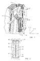
- FIGS 1 and 2 show axially extending slots 12 formed along the stator 10.
- the slots 12 are sized and configured to accept and secure at least one strand assembly 14 (or vice-versa).
- Each strand assembly 14 preferably comprises a plurality of transposed (e.g. roebelled) conductive (e.g. copper) strands 16 that are sheathed by an insulator 18 (e.g. dacron-glass), with a conductive filler 20 (e.g. mica) disposed about (completely or partially) the insulated 18 strands 16, and an isolation layer 22 disposed about (completely or partially) the conductive filler 20.
- transposed e.g. roebelled
- conductive filler 20 e.g. mica
- isolation layer 22 disposed about (completely or partially) the conductive filler 20.
- numerous other types of transpositions, strands 16, insulators 18, and fillers 20 can be used to form the strand assembly 14. Additional elements can also be used.
- the isolation layer 22 is advantageously arranged between the insulated 18 strands 16 (the insulated strands hereinafter referenced as 24) and the filler 20 to electrically isolate the insulated strands 24 from the filler 20.
- the isolation layer 22 is advantageously arranged between the insulated 18 strands 16 (the insulated strands hereinafter referenced as 24) and the filler 20 to electrically isolate the insulated strands 24 from the filler 20.
- the isolation layer 22 preferably has at least one of the following characteristics, more preferably most of the following characteristics, and most preferably all of the following characteristics.
- the isolation layer 22 is a dielectric isolate conductive materials and to distribute voltage across it during stator 10 operation.
- the isolation layer 22 is flexible to generally conform to adjacent surfaces and thereby inhibit gaps from forming between itself and the adjacent surfaces.
- the isolation layer 22 is bondable to adjacent surfaces and thereby inhibits gaps from forming between itself and adjacent surfaces.
- the isolation layer 22 is capable of withstanding the environment within which it operates.
- the isolation layer 22 should have a dielectric strength of at least 300 volts per millimeter and preferably at least 500 volts per millimeter.
- Suitable dielectrics include polymers such as polyphenylene sulfide, polythiophene, polyacetylene and polypropylene, glass such as E-glass and S-glass, epoxy, resin, fabrics having NOMEX, KEVLAR or similar fibers, mica, and the like.
- NOMEX and KELVAR are registered trademarks of E.I. DuPont De Nemours and Company.
- the isolation layer 22 should be sufficiently flexible to conform to the irregularities that characterize the insulated strand 24 surface caused by the roebel offsets (e.g. hills and valleys) or other surface irregularities.
- Suitable materials that may be inherently sufficiently flexible for this purpose include polymers, epoxy, fabric, mica, laminates, and the like. Semi-rigid materials may also be used, as well as rigid materials that are spun laced and the like. These materials are preferably formed as a felt, tape, and the like but can also be embodied in other forms so long as they provide the sufficient flexibility.
- the isolation layer 22 should be suitably bondable to adhere to adjacent surfaces and thereby inhibit gaps from forming between itself and the adjacent surfaces. Suitable bonding can be achieved by covering the isolation layer 22 with an adhesive 26 such as epoxy, acrylic and the like, or using a material that is inherently suitably bonding. If an adhesive 26 is used, the adhesive 26 can partially or completely cover the isolation layer 22 , and could cover one or more sides or portions of the isolation layer 22.
- the adhesive 26 is advantageously thermally activated so that it cures during the stand assembly 14 curing process, discussed in more detail below. The adhesive need not have a uniform thickness.
- the isolation layer 22 should be capable of withstanding the environment within which it operates, including withstanding stator temperatures of at least 130° C and preferably at least 155° C. Suitable materials include resins, plastics, NOMEX, epoxies, and the like.
- an isolation layer 22 preferably comprising a NOMEX spun laced felt material (such as one commercially available by the Electrolock, Inc. company of Hiram, Ohio) and coated on one side with an epoxy adhesive, (such as one commercially available by Eletrolock, Inc.), can meet the above-described preferred characteristics.
- a NOMEX spun laced felt material such as one commercially available by the Electrolock, Inc. company of Hiram, Ohio
- an epoxy adhesive such as one commercially available by Eletrolock, Inc.
- suitable materials include low temperature DACRON and the like.
- the isolation layer 22 is preferably arranged between the insulated strands 24 and the filler 20 to electrically isolate the insulated strands 24 from the filler 20 so that the filler 20 cannot pass or bleed through the porous strand insulation 18 voids and into the strands 16.
- the isolation layer 22 is preferably placed above the upper surface (Z-Z) of the insulated strands 24 and below the lower surface (Z-Z) of the insulated strands 24, but below the upper surface (Z-Z) of the filler 20 and above the lower surface (Z-Z) of the filler 20.
- the width (X-X) of the isolation layer 22 is advantageously about 0.1 to about 2 inches, preferably about 0.5 inches, wider than the width of the insulated strands 24 so that the ends 28 of the isolation layer 22 can extend or wrap along the edges 30 of the insulated strands 24 in order to isolate any filler 20 that may extend along the edges 30 of the insulated strands 24 (best shown in Figure 1).
- the isolation layer 22 could alternatively be arranged to completely surround the insulated strands 24, and not leave the edges 30 of the insulated strands 24 uncovered.
- the isolation layer 22 should accordingly be arranged differently such that it is between (completely or partially) and isolates the insulated strands 24 and the filler 20.
- a section, preferably a side 32, of the isolation layer 22 is covered with the epoxy adhesive 26 and adhered to at least a portion of the insulated strands 24.
- the adhesive 26 could be placed on two sides 32 of the isolation layer 22 to adhere to the insulated strands 24 and filler 20, or could not be placed on any side 32 of the isolation layer 22 to merely interpose (but not adhere to) the insulated strands 24 and filler 20.
- the strand assembly 14 can be made by first roebelling the insulated strands 24.
- the isolation material 22 is then placed on the upper and lower portions of the insulated strands 24 as described in connection with Figure 2A above, or sheathed around the insulated strands 24 as described in connection with Figure 2B.
- the filler 20 is placed on the isolation layer 22 to form the strand assembly 14.
- the strand assembly 14 is then cured by heating at a temperature of about 150° and a pressure of about 500 psi for about 120 minutes, as is known by those skilled in the art.
- two conventional coils (A, B), each comprising about 40 roebelled insulated strands 24, were processed in accordance with the above teachings of the present invention and as commonly understood by those skilled in the art.
- a strand-to-strand test was performed at a test voltage of 250 VDC. All readings were well above 20 Mega ohm and no strand-to-strand low resistance connections were found.
- a second strand-to-strand test was also performed after forming the coil end turns of the coils A, B, with similar results.
- the two coils A, B were then insulated with groundwall insulation, and then impregnated and cured.
- a third strand-to-strand test performed at 250VDC. All readings were above 100 Mega ohms.
Landscapes
- Engineering & Computer Science (AREA)
- Power Engineering (AREA)
- Insulation, Fastening Of Motor, Generator Windings (AREA)
Abstract
Description
Claims (15)
- An electrical isolation layer system, comprising:a first conductive material comprising a plurality of copper strands;a second conductive material comprising a roebel filler; anda nomex spun laced felt having a dielectric strength of at least 300 volts per millimeter interposed at least partially between the copper strands and the roebel filler.
- The isolation layer system of claim 1, wherein the felt has a dielectric strength of at least 500 volts per millimeter.
- The isolation layer system of claims 1 or 2, wherein the plurality of copper strands include at least 30 roebelled copper strands.
- The isolation layer system of claim 3, wherein the copper strands are sheathed by a porous insulating material.
- The isolation layer system of claims 1 to 4, wherein the roebel filler includes a mica material.
- The isolation layer system of claims 1 to 5, wherein the felt is arranged above the upper surface of the copper strands and below the lower surface of the roebel filler.
- The isolation layer system of claims 1 to 5, wherein the felt is arranged below the upper surface of the copper strands and above the lower surface of the roebel filler.
- The isolation layer system of claims 1 to 7, wherein the felt is arranged to sheath at least one copper strand.
- The isolation layer system of claim 8, wherein the felt is arranged to sheath all the copper strands.
- The isolation layer system of claims 1 to 9, wherein the isolation layer has an adhesive coated on at least one side of the isolation layer.
- A strand assembly for use within a stator of a dynamoelectric machine of a power generation plant, comprising:a plurality of roebelled conductive strands that extend along a generator length;an insulator sheathing each of the strands;a conductive filler at least partially surrounding the insulated strands; andan electrical isolation layer disposed at least partially between the insulated strands and the conductive filler material.
- The strand assembly of claim 11, wherein the isolation layer has a dielectric strength of at least 300 volts per millimeter.
- The strand assembly of claims 11 or 12, wherein the isolation layer comprises a nomex spun laced felt.
- The strand assembly of claims 11 to 13, wherein the isolation layer has an adhesive covering at least one side of the isolation layer.
- The strand assembly of claims 11 to 14, wherein the isolation layer can withstand an operating temperature of at least 130° C.
Applications Claiming Priority (2)
| Application Number | Priority Date | Filing Date | Title |
|---|---|---|---|
| US880583 | 2001-06-13 | ||
| US09/880,583 US6724118B2 (en) | 2001-06-13 | 2001-06-13 | Electrical isolation layer system strand assembly and method of forming for electrical generator |
Publications (3)
| Publication Number | Publication Date |
|---|---|
| EP1267472A2 true EP1267472A2 (en) | 2002-12-18 |
| EP1267472A3 EP1267472A3 (en) | 2004-10-20 |
| EP1267472B1 EP1267472B1 (en) | 2011-07-06 |
Family
ID=25376592
Family Applications (1)
| Application Number | Title | Priority Date | Filing Date |
|---|---|---|---|
| EP02076907A Expired - Lifetime EP1267472B1 (en) | 2001-06-13 | 2002-05-16 | Electrical isolation layer for generator stator strand assembly and other uses |
Country Status (2)
| Country | Link |
|---|---|
| US (1) | US6724118B2 (en) |
| EP (1) | EP1267472B1 (en) |
Cited By (2)
| Publication number | Priority date | Publication date | Assignee | Title |
|---|---|---|---|---|
| DE10304025A1 (en) * | 2003-02-01 | 2004-08-05 | Alstom Technology Ltd | Roebel bar for an electrical machine and method for producing such a Roebel bar |
| NL2005439C2 (en) * | 2010-10-01 | 2012-04-03 | Draad Nijmegen B V | A multiple parallel conductor for an electrical machine. |
Families Citing this family (9)
| Publication number | Priority date | Publication date | Assignee | Title |
|---|---|---|---|---|
| DE102004008784B3 (en) * | 2004-02-23 | 2005-09-15 | Infineon Technologies Ag | Process for the through-contacting of field effect transistors with a self-assembled monolayer of an organic compound as a gate dielectric |
| US8030818B2 (en) * | 2004-06-15 | 2011-10-04 | Siemens Energy, Inc. | Stator coil with improved heat dissipation |
| US7893357B2 (en) * | 2007-03-20 | 2011-02-22 | Electrolock, Inc. | Roebel winding with conductive felt |
| US7812260B2 (en) * | 2007-09-25 | 2010-10-12 | Siemens Energy, Inc. | Electrical insulation tape with controlled bonding and resin impregnation properties |
| US8278795B2 (en) * | 2009-09-18 | 2012-10-02 | Siemens Energy, Inc. | Voltage grading structure in a high-voltage stator coil of an electromotive machine |
| US8872405B2 (en) | 2012-02-01 | 2014-10-28 | Siemens Energy, Inc. | High voltage stator coil with reduced power tip-up |
| WO2013145344A1 (en) * | 2012-03-27 | 2013-10-03 | 三菱電機株式会社 | Stator and dynamo-electric machine with same |
| JP5718854B2 (en) * | 2012-05-09 | 2015-05-13 | トヨタ自動車株式会社 | Inflatable sheet for rotating electrical machine, stator for rotating electrical machine using the expanded sheet for rotating electrical machine, and method for manufacturing stator for rotating electrical machine |
| JP7383899B2 (en) * | 2019-03-29 | 2023-11-21 | 株式会社デンソー | rotating electric machine |
Family Cites Families (50)
| Publication number | Priority date | Publication date | Assignee | Title |
|---|---|---|---|---|
| US1784997A (en) * | 1928-07-02 | 1930-12-16 | Westinghouse Electric & Mfg Co | Corona elimination in dynamo-electric machines |
| US2707204A (en) * | 1951-10-31 | 1955-04-26 | Gen Electric | Treated mica paper insulation |
| US2705292A (en) * | 1953-05-07 | 1955-03-29 | Siemens Ag | Slot conductor for dynamoelectric machines |
| CA589294A (en) * | 1955-07-13 | 1959-12-22 | L. Marshall Walter | Adhesive silicone rubber sheet material and tapes and method of preparing the same |
| US2939976A (en) * | 1956-08-31 | 1960-06-07 | Westinghouse Electric Corp | Corona suppression in high voltage coils |
| US2917570A (en) * | 1957-04-25 | 1959-12-15 | Gen Electric | Composite mica paper, mica flake electrical insulating material |
| US2970936A (en) * | 1957-12-12 | 1961-02-07 | Gen Electric | Insulated electrical coils |
| US3311514A (en) * | 1962-09-07 | 1967-03-28 | Hitachi Ltd | Method for manufacturing electrically insulated coils |
| US3308414A (en) * | 1964-01-14 | 1967-03-07 | Anaconda Wire & Cable Co | Porous-refractory encapsulant for cous and coil encapsulated therewith |
| US3462544A (en) * | 1967-08-29 | 1969-08-19 | Us Navy | Electrical conductors with a heat resistant electrical insulation system |
| US3679925A (en) * | 1971-02-02 | 1972-07-25 | Westinghouse Electric Corp | Electrical apparatus with corona suppression means |
| JPS4899647A (en) * | 1972-03-31 | 1973-12-17 | ||
| US3960803A (en) * | 1973-06-22 | 1976-06-01 | Westinghouse Electric Corporation | Flexible nontacky prepreg for bonding coils in high voltage devices and method of making said prepreg |
| SE440709B (en) * | 1976-06-10 | 1985-08-12 | Asea Ab | IF USING AN EXTENSION MACHINE ON AN INSULATION OF NON-CIRCUIT OR CROSS-POLYTEN PROVIDED CABLES, APPLY A LEADING, REMOVABLE LAYER |
| DE2655609C2 (en) * | 1976-12-06 | 1984-05-17 | Siemens AG, 1000 Berlin und 8000 München | Winding an electrical machine |
| US4278905A (en) * | 1977-12-27 | 1981-07-14 | Electric Power Research Institute | Apparatus for supporting a stator winding in a superconductive generator |
| DE3031866A1 (en) * | 1980-08-23 | 1982-04-01 | Brown, Boveri & Cie Ag, 6800 Mannheim | LADDER BAR FOR ELECTRICAL MACHINE |
| US4399190A (en) * | 1981-03-11 | 1983-08-16 | Mitsubishi Denki Kabushiki Kaisha | Thin insulating mica sheet and insulated coil |
| US4540967A (en) * | 1982-06-28 | 1985-09-10 | Mitsubishi Denki Kabushiki Kaisha | Molded transformer with grounded electrically conductive layer |
| US5067046A (en) * | 1984-08-23 | 1991-11-19 | General Electric Company | Electric charge bleed-off structure using pyrolyzed glass fiber |
| US5066881A (en) * | 1984-08-23 | 1991-11-19 | General Electric Company | Semi-conducting layer for insulated electrical conductors |
| SE457031B (en) * | 1987-03-24 | 1988-11-21 | Asea Ab | ELECTRIC conductor is provided with a surrounding insulation comprising a layer of an organic polymer and the use of the conductor in a harrow. |
| US5175396A (en) * | 1990-12-14 | 1992-12-29 | Westinghouse Electric Corp. | Low-electric stress insulating wall for high voltage coils having roebeled strands |
| JPH04296316A (en) * | 1990-12-18 | 1992-10-20 | General Electric Co <Ge> | Heat-resistant resin composition and its product and manufacture |
| DE4104868A1 (en) * | 1991-02-17 | 1992-08-20 | Moderne Maschinen Apparate Wer | ISOLATED WINDING AND METHOD AND SEMI-FINISHED MATERIAL FOR THEIR MANUFACTURE |
| US5246783A (en) * | 1991-08-15 | 1993-09-21 | Exxon Chemical Patents Inc. | Electrical devices comprising polymeric insulating or semiconducting members |
| ATE130132T1 (en) * | 1991-09-13 | 1995-11-15 | Siemens Ag | IMPREGNABLE ARRANGEMENT COMPRISING A SUPPORT BODY AND WINDING ELEMENTS. |
| US5306976A (en) * | 1993-01-29 | 1994-04-26 | General Electric Company | Motor and stationary assembly therefor having end caps and overlapping film slot insulation |
| US5633477A (en) * | 1994-05-16 | 1997-05-27 | Westinghouse Electric Corporation | Electrically conductive prepreg for suppressing corona discharge in high voltage devices |
| US5723920A (en) * | 1994-10-12 | 1998-03-03 | General Electric Company | Stator bars internally graded with conductive binder tape |
| WO1996026973A1 (en) * | 1995-02-28 | 1996-09-06 | Kanegafuchi Kagaku Kogyo Kabushiki Kaisha | Film having excellent corona resistance and insulated wire, coil, and motor using it as insulating material |
| US5945764A (en) * | 1995-07-18 | 1999-08-31 | Siemens Aktiengesellschaft | Winding element for an electrical machine, assembly and set having a plurality of winding elements |
| US6225564B1 (en) * | 1995-08-24 | 2001-05-01 | Voith Siemens Hydro Power Generation Inc. | Coil turn insulation system for high voltage machines |
| DE19543122A1 (en) * | 1995-11-18 | 1997-05-22 | Asea Brown Boveri | Ladder staff |
| US5973269A (en) * | 1996-04-16 | 1999-10-26 | General Electric Canada Inc. | Multi-layer insulation for winding elements of dynamoelectric machines (D.E.M.s) |
| TW374181B (en) * | 1996-08-22 | 1999-11-11 | Furukawa Electric Co Ltd | Multilayer insulated wire and transformer using the same |
| JPH11176244A (en) * | 1997-10-06 | 1999-07-02 | Furukawa Electric Co Ltd:The | Multilayer insulated wire and transformer using the same |
| JPH11176245A (en) * | 1997-10-14 | 1999-07-02 | Furukawa Electric Co Ltd:The | Multilayer insulated wire and transformer using the same |
| JPH11176246A (en) * | 1997-10-24 | 1999-07-02 | Furukawa Electric Co Ltd:The | Multilayer insulated wire and transformer using the same |
| AT406923B (en) * | 1998-02-24 | 2000-10-25 | Asta Elektrodraht Gmbh | MULTIPLE PARALLEL LADDER FOR ELECTRICAL MACHINES AND DEVICES |
| JP3458693B2 (en) * | 1998-02-27 | 2003-10-20 | 株式会社日立製作所 | Insulation and electric winding |
| WO2000003859A1 (en) * | 1998-07-16 | 2000-01-27 | Idemitsu Petrochemical Co., Ltd. | Lightweight resin molded product and production method thereof |
| US6043582A (en) * | 1998-08-19 | 2000-03-28 | General Electric Co. | Stable conductive material for high voltage armature bars |
| US6228494B1 (en) * | 1998-12-02 | 2001-05-08 | Siemens Westinghouse Power Corporation | Method to reduce partial discharge in high voltage stator coil's roebel filler |
| US6524702B1 (en) * | 1999-08-12 | 2003-02-25 | Dow Global Technologies Inc. | Electrical devices having polymeric members |
| US6509665B1 (en) * | 1999-10-25 | 2003-01-21 | Matsushita Electric Industial Co., Ltd. | Motor having stator with insulator of high heat-conductivity |
| TW495771B (en) * | 2000-01-25 | 2002-07-21 | Furukawa Electric Co Ltd | Multilayer insulated wire and transformer using the same |
| US6498415B1 (en) * | 2000-09-06 | 2002-12-24 | Siemens Westinghouse Power Corporation | High voltage stator coil having low loss insulator and electrode covering and method therefor |
| US6420812B1 (en) * | 2000-09-07 | 2002-07-16 | Siemens Westinghouse Power Corporation | High voltage generator stator coils and methods of forming same |
| JP2003088026A (en) * | 2001-09-07 | 2003-03-20 | Moric Co Ltd | Armature insulator for rotating electrical equipment |
-
2001
- 2001-06-13 US US09/880,583 patent/US6724118B2/en not_active Expired - Lifetime
-
2002
- 2002-05-16 EP EP02076907A patent/EP1267472B1/en not_active Expired - Lifetime
Cited By (3)
| Publication number | Priority date | Publication date | Assignee | Title |
|---|---|---|---|---|
| DE10304025A1 (en) * | 2003-02-01 | 2004-08-05 | Alstom Technology Ltd | Roebel bar for an electrical machine and method for producing such a Roebel bar |
| US6960859B2 (en) | 2003-02-01 | 2005-11-01 | Alstom Technology Ltd | Roebel bar for an electrical machine and method for producing such a roebel bar |
| NL2005439C2 (en) * | 2010-10-01 | 2012-04-03 | Draad Nijmegen B V | A multiple parallel conductor for an electrical machine. |
Also Published As
| Publication number | Publication date |
|---|---|
| EP1267472A3 (en) | 2004-10-20 |
| US20030000732A1 (en) | 2003-01-02 |
| US6724118B2 (en) | 2004-04-20 |
| EP1267472B1 (en) | 2011-07-06 |
Similar Documents
| Publication | Publication Date | Title |
|---|---|---|
| US9590460B2 (en) | Electric machine with a slot liner | |
| KR101464628B1 (en) | Wrapped stator coil | |
| CZ388298A3 (en) | Rotary electric machine for high voltage with magnetic circuit and process for producing thereof | |
| JPH077878A (en) | Wall structure for insulating the outer surface of a high voltage component and method for forming the same | |
| WO2012149297A2 (en) | Electric machine module insulation system and method | |
| CA1042495A (en) | Coil end insulation for dynamoelectric machines | |
| US6724118B2 (en) | Electrical isolation layer system strand assembly and method of forming for electrical generator | |
| US20200336035A1 (en) | Insulation of sub-conductors of a dynamoelectric machine | |
| CN1129995C (en) | Conductor winding arrangement for heavy electric machine | |
| US7705243B2 (en) | Electrical-discharge-inhibiting conformable layer for use in inner-cooled coils | |
| CN1220048A (en) | A rotating electric machine and its manufacturing method | |
| EP2810358B1 (en) | High voltage stator coil with reduced power tip-up | |
| KR20010080595A (en) | Method to reduce partial discharge in high voltage stator coil's roebel filler | |
| EP1171941A1 (en) | Improvements in electrical machines | |
| US20190280550A1 (en) | Laminated stack motor | |
| US20050054250A1 (en) | Integral slip layer for insulating tape | |
| US20140300241A1 (en) | Electrical machine medium voltage coil insulation systems and methods | |
| JP3736821B2 (en) | Insulated wire ring of rotating electrical machine | |
| US9543800B2 (en) | External corona shielding for an electrical machine | |
| JP2010226814A (en) | Rotating electrical machine rotor | |
| Fawaz et al. | Evaluation of the Electrical Insulation System of Stator Tooth Winding for high-power density PMSM | |
| JPH11346450A (en) | Stator coil of high-pressure rotating machine |
Legal Events
| Date | Code | Title | Description |
|---|---|---|---|
| PUAI | Public reference made under article 153(3) epc to a published international application that has entered the european phase |
Free format text: ORIGINAL CODE: 0009012 |
|
| AK | Designated contracting states |
Kind code of ref document: A2 Designated state(s): AT BE CH CY DE DK ES FI FR GB GR IE IT LI LU MC NL PT SE TR |
|
| AX | Request for extension of the european patent |
Free format text: AL;LT;LV;MK;RO;SI |
|
| PUAL | Search report despatched |
Free format text: ORIGINAL CODE: 0009013 |
|
| AK | Designated contracting states |
Kind code of ref document: A3 Designated state(s): AT BE CH CY DE DK ES FI FR GB GR IE IT LI LU MC NL PT SE TR |
|
| AX | Request for extension of the european patent |
Extension state: AL LT LV MK RO SI |
|
| 17P | Request for examination filed |
Effective date: 20041104 |
|
| 17Q | First examination report despatched |
Effective date: 20050211 |
|
| AKX | Designation fees paid |
Designated state(s): DE FR GB IT |
|
| RAP1 | Party data changed (applicant data changed or rights of an application transferred) |
Owner name: SIEMENS POWER GENERATION, INC. |
|
| RAP1 | Party data changed (applicant data changed or rights of an application transferred) |
Owner name: SIEMENS ENERGY, INC. |
|
| GRAP | Despatch of communication of intention to grant a patent |
Free format text: ORIGINAL CODE: EPIDOSNIGR1 |
|
| GRAS | Grant fee paid |
Free format text: ORIGINAL CODE: EPIDOSNIGR3 |
|
| GRAA | (expected) grant |
Free format text: ORIGINAL CODE: 0009210 |
|
| AK | Designated contracting states |
Kind code of ref document: B1 Designated state(s): DE FR GB IT |
|
| REG | Reference to a national code |
Ref country code: GB Ref legal event code: FG4D |
|
| REG | Reference to a national code |
Ref country code: DE Ref legal event code: R096 Ref document number: 60240433 Country of ref document: DE Effective date: 20110825 |
|
| PLBE | No opposition filed within time limit |
Free format text: ORIGINAL CODE: 0009261 |
|
| STAA | Information on the status of an ep patent application or granted ep patent |
Free format text: STATUS: NO OPPOSITION FILED WITHIN TIME LIMIT |
|
| 26N | No opposition filed |
Effective date: 20120411 |
|
| REG | Reference to a national code |
Ref country code: DE Ref legal event code: R097 Ref document number: 60240433 Country of ref document: DE Effective date: 20120411 |
|
| REG | Reference to a national code |
Ref country code: FR Ref legal event code: PLFP Year of fee payment: 15 |
|
| REG | Reference to a national code |
Ref country code: FR Ref legal event code: PLFP Year of fee payment: 16 |
|
| PGFP | Annual fee paid to national office [announced via postgrant information from national office to epo] |
Ref country code: IT Payment date: 20170526 Year of fee payment: 16 |
|
| REG | Reference to a national code |
Ref country code: FR Ref legal event code: PLFP Year of fee payment: 17 |
|
| PGFP | Annual fee paid to national office [announced via postgrant information from national office to epo] |
Ref country code: NL Payment date: 20180718 Year of fee payment: 8 |
|
| PG25 | Lapsed in a contracting state [announced via postgrant information from national office to epo] |
Ref country code: IT Free format text: LAPSE BECAUSE OF NON-PAYMENT OF DUE FEES Effective date: 20180516 |
|
| PGFP | Annual fee paid to national office [announced via postgrant information from national office to epo] |
Ref country code: FR Payment date: 20190517 Year of fee payment: 18 |
|
| PGFP | Annual fee paid to national office [announced via postgrant information from national office to epo] |
Ref country code: GB Payment date: 20190509 Year of fee payment: 18 |
|
| REG | Reference to a national code |
Ref country code: DE Ref legal event code: R119 Ref document number: 60240433 Country of ref document: DE |
|
| PG25 | Lapsed in a contracting state [announced via postgrant information from national office to epo] |
Ref country code: DE Free format text: LAPSE BECAUSE OF NON-PAYMENT OF DUE FEES Effective date: 20191203 |
|
| GBPC | Gb: european patent ceased through non-payment of renewal fee |
Effective date: 20200516 |
|
| PG25 | Lapsed in a contracting state [announced via postgrant information from national office to epo] |
Ref country code: GB Free format text: LAPSE BECAUSE OF NON-PAYMENT OF DUE FEES Effective date: 20200516 Ref country code: FR Free format text: LAPSE BECAUSE OF NON-PAYMENT OF DUE FEES Effective date: 20200531 |