EP1267364A2 - Color arrangement of electrical cables e.g. for automobiles - Google Patents
Color arrangement of electrical cables e.g. for automobiles Download PDFInfo
- Publication number
- EP1267364A2 EP1267364A2 EP02291453A EP02291453A EP1267364A2 EP 1267364 A2 EP1267364 A2 EP 1267364A2 EP 02291453 A EP02291453 A EP 02291453A EP 02291453 A EP02291453 A EP 02291453A EP 1267364 A2 EP1267364 A2 EP 1267364A2
- Authority
- EP
- European Patent Office
- Prior art keywords
- critical
- wire harness
- different color
- unitary wire
- connectors
- Prior art date
- Legal status (The legal status is an assumption and is not a legal conclusion. Google has not performed a legal analysis and makes no representation as to the accuracy of the status listed.)
- Withdrawn
Links
Images


Classifications
-
- H—ELECTRICITY
- H01—ELECTRIC ELEMENTS
- H01B—CABLES; CONDUCTORS; INSULATORS; SELECTION OF MATERIALS FOR THEIR CONDUCTIVE, INSULATING OR DIELECTRIC PROPERTIES
- H01B7/00—Insulated conductors or cables characterised by their form
- H01B7/36—Insulated conductors or cables characterised by their form with distinguishing or length marks
-
- H—ELECTRICITY
- H01—ELECTRIC ELEMENTS
- H01B—CABLES; CONDUCTORS; INSULATORS; SELECTION OF MATERIALS FOR THEIR CONDUCTIVE, INSULATING OR DIELECTRIC PROPERTIES
- H01B13/00—Apparatus or processes specially adapted for manufacturing conductors or cables
- H01B13/34—Apparatus or processes specially adapted for manufacturing conductors or cables for marking conductors or cables
Definitions
- the present invention relates to a wire harness, e.g. for vehicle automotive applications, which comprises several unitary wire harnesses respectively containing a plurality of electrical cables.
- the invention concerns colored electrical cables and aims to rationalize the use of colors while reducing connection errors, thereby lowering harness production costs.
- a typical automobile is usually wired with hundreds of electrical cables. These electrical cables are assembled into several unitary wire harnesses, each unitary wire harness being assigned to a specific car section.
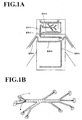
- such unitary wire harnesses include, for instance, an engine compartment harness W/H-1, an engine harness W/H-2 wired above the engine, a cowl harness W/H-3 wired in the dash panel (cowl panel), an instrument panel harness W/H-4, a floor harness W/H-5 wired from the front side to the rear side along the car floor, a door harness W/H-6 wired in the doors on both sides, and a roof harness (not shown in the figure) wired along the car roof.
- a large-scale wire harness such as an engine harness, an engine compartment harness, a cowl harness and an instrument panel harness, contains at least 30 to 50, and typically 100 to 300 electrical cables.
- a number of electrical cables W are bundled and taped, so as to form a trunk section and branch sections.
- Each end portion of the electrical cables is terminated with a connector 10.
- determined positions of the trunk and branch sections are mounted with fitting members such clips to be hooked to car body, protectors for safeguarding the harness, or corrugated tubes.
- each electrical cable W is fitted with an electrical terminal T, and the latter is inserted into a corresponding terminal enclosure a, b or c, etc., formed in a connector 10.
- the electrical cables are differentiated by colors.
- a first electrical cable 5 is composed of a core wire aggregate 1 and an insulator coating 2.
- the latter has a plain (or solid) base color 3a (i.e. dominant or background color) in red, blue, yellow, green, black or the like.
- a second electrical cable 6 has a plain base color 3a same as for the first electrical cable 5, and is further provided with e.g. two stripes 3b.
- the plain base colors 3a and colors of the stripes are thereby differentiated, so that workers can differentiate those electrical cables.
- the base color 3a may be provided in the entire insulator coating 2, or only on its external surface.
- the stripes 3b are colored only on the external surface of the insulator coating.
- the first and second electrical cables W may be respectively spotted with identification codes 3c in silver, red or black etc. at given intervals along their length.
- the shape of the identification codes 3c is a function of the material and thickness of the insulator coating, the diameter of the core wire aggregate, the size of the electrical cable, etc..
- these designation identification codes 3c are not included in the so-called cable colors in the sense of the invention, beside the plain base colors 3a and the striped cable colors 3b.
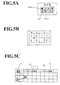
- a work bench for mounting unitary wire harnesses is usually provided with an arrangement table such as shown e.g. in Fig.5A.
- the color of an electrical cable W is made to correspond to a particular terminal enclosure among a plurality of terminal receiving means of connector 10, to which the cables are to be inserted, so that erroneous connections can be avoided.
- the cable color sets are differentiated as a function of the destination of the electrical cables W (e.g. electrical cables W destined for a circuit).
- a circuit can thus be connected by inserting a given colored cable into the corresponding terminal enclosure.
- One difficulty of harness arrangement resides in the fact that connectors 10 in an automobile are initially joined to existing electric parts e.g. electronic control units and junction boxes, and the connections of unitary wire harnesses must be adapted to these situations. Further, a unitary wire harness may be connected between several connectors 10 by crossing with other partially-connected wire harnesses, so that the electrical cables of one harness intertwine with those of other harnesses, and it is often difficult to attribute these cables to their terminal receiving means in a single minded way.
- the electrical cables W to be engaged into terminal receiving means are identified by the corresponding cable colors.
- the types of color to be used must also be multiplied so as to avoid misconnections.
- the present invention thus has for object to reduce the types of cable color required without risk of connection errors, to reduce the manufacturing costs of cables, and to alleviate fatigue on workers due to color differentiation efforts.
- the wire harness comprises a plurality of unitary wire harnesses to be engaged with a given number of connectors.
- Each of the unitary wire harnesses contains a plurality of electrical cables which respectively have a different color marking and comprise an electrical terminal attached to at least one end thereof, whilst each of the connectors includes a plurality of terminal receiving means respectively adapted to receive a corresponding electrical terminal, so that each of the unitary wire harnesses can be engaged with a given number of connectors.
- the above method further comprises the steps of:
- the above step of selecting a critical unitary wire harness may comprise choosing a unitary wire harness containing either the greatest number of electrical cables or the greatest number of connectors.
- the above step of determining the critical number of different color markings may comprise multiplying member R by a number equal to at least about 1.5, when C / B is less than 9.
- the above number equal to at least about 1.5 is a number comprised between about 1.5 and about 2.0 inclusive .
- the above step of determining the critical number of different color markings may comprise rounding up R to the nearest higher integer value, when said member R is a decimal number.
- the above different color markings include a plain base color and/or a striped base color.
- the different color markings are composed solely of plain base colors.
- the different color markings comprise 13 types of color at the maximum.
- all of the different color markings used for a specific connector are different from one another, or the terminal receiving means in a specific connector are arranged such that either the same color markings are not placed in adjacent positions, or are placed in different sub-classes which are defined for the terminal receiving means.
- step of selecting a critical unitary wire harness may comprise choosing a unitary wire harness containing at least 30 electrical cables.
- the different color markings may further be spotted with identification codes along the length of the electrical cables at given intervals.
- the invention also relates to a system for determining a critical number of colors for the electrical cables constituting a wire harness e.g. for automotive applications, the wire harness comprising a plurality of unitary wire harnesses to be engaged with a given number of connectors, each of the unitary wire harnesses containing a plurality of electrical cables which respectively have a different color marking and comprise an electrical terminal attached to at least one end thereof, whilst each of the connectors includes a plurality of terminal receiving means respectively adapted to receive a corresponding electrical terminal, so that each of the unitary wire harnesses can be engaged with a given number of connectors.
- the above system comprises:
- the means for selecting a critical unitary wire harness may comprise means for choosing a unitary wire harness containing either the greatest number of electrical cables or the greatest number of connectors.
- the means for determining the critical number of different color markings may comprise means for multiplying member R by a number equal to at least about 1.5, when C / B is less than 9.
- the different color markings include a plain base color and/or a striped base color.
- the different color markings comprise 13 types of color at the maximum.
- the invention further concerns a wire harness, e.g. for automotive applications, comprising a plurality of unitary wire harnesses to be engaged with a given number of connectors, each of the unitary wire harnesses containing a plurality of electrical cables which respectively have a different color marking and comprise an electrical terminal attached to at least one end thereof, the unitary wire harnesses being adapted to be engaged with the connectors including a plurality of terminal receiving means for receiving a corresponding electrical terminal.
- the above wire harness comprises:
- the above critical unitary wire harness may comprise a unitary wire harness containing either the greatest number of electrical cables or the greatest number of connectors.
- the critical number of different color markings comprises member R multiplied by a number at least equal to about 1.5, when C / B is less than 9.
- the different color markings include a plain base color and/or a striped base color and comprise 13 types of color at the maximum.
- the required number of different color markings for the invention are related to the number of electrical cables, the number of connectors, and the number of terminal receiving means contained in a connector. These numbers are therefore taken into consideration in the above formula.
- the critical number of different color markings is defined for a particular unitary wire harness, so that the electrical cables, to be engaged into the terminal receiving means of one connector, do not have a same cable color.
- the number of cable colors for the other unitary wire harnesses is then limited to be equal to or less than the above critical number.
- the first member A / B of the above empirical formula gives the mean value of electrical cables per connector. When this mean value increases, the critical number of different color markings also tends to increase.
- the second member C / B of the above empirical formula gives the mean value of terminal receiving means per connector. When this mean value increases, the critical different color markings also tends to increase.
- both mean values decrease.
- the critical number R is multiplied by a correction factor for security of at least about 1.5, preferably a number chosen between about 1.5 and about 2.0 inclusive. This correction factor is obtained empirically, a value of less than about 1.5 or over about 2.0 being found not to be entirely satisfactory.
- the critical number of different color markings R is not multiplied by a number of at least about 1.5, whilst, when the mean cavity number per connector is less than 9, the critical number R is multiplied by a number equal to at least about 1.5.
- the greatest number of terminal receiving means may be used for determining the critical unitary wire harness for the above calculation.
- the connector to be engaged with a unitary wire harness includes a mean number of terminal receiving means of at least 9, the number of different color markings for all the unitary wire harnesses may be equal to or less than the critical number R.
- the unitary wire harness containing the greatest number of electrical cables is engaged with the largest-scale connector (having the greatest number of terminal receiving means).
- a unitary wire harness not containing the greatest number of electrical cables may be engaged with the largest-scale connector.
- electrical cables are differentiated by many colors in order to avoid connection errors to a large-scale connector. Accordingly, in the above case, the critical number of different color markings of formula (I) is calculated on the basis of the unitary wire harness to which the largest-scale connector is engaged.
- all the electrical cables wired e.g. in the entire automobile may be painted in a base color without having to add stripes.
- the cable colors can be identified more easily when they are not striped.
- the use of "stripeless" cable colors thus alleviate the burden on workers.
- the plain base colors and the base colors striped in another color may be used jointly, and their total cable colors may be brought to a number equal to or less than the critical number of different color markings.
- the unitary wire harnesses containing the number of different color markings equal to or less than the value obtained by formula (I) may include a total of at least 30, at least 50 or at least 100 electrical cables, the last being the most common.
- the engine harness, the engine compartment harness or the instrument panel harness contains a great number of electrical cables.
- the number of their different color markings is at most the critical number obtained from the above formula.
- the roof harness or the door harness contains a smaller number of electrical cables, and consequently a smaller number of distinguishing cable colors than that obtained from the formula above.
- the unitary wire harness containing the greatest number of electrical cables may be taken as critical harness, and the critical number of different color markings may be calculated. As already mentioned, this critical number of distinguishing cable colors may also be applied to unitary wire harnesses having a smaller cable number. Likewise, the number of different color markings used e.g. in the entire automobile can be calculated from formula (I).
- the critical number of different color markings thus calculated amounts to a value ranging from 12 to 14, especially to 13.
- the number of different color markings used for e.g. the entirety of the vehicle's electrical cables is determined to be 12 to 14 types at the most, preferably 13 types.
- the above number of different color markings for electrical cables may be composed of plain base colors only, or may be a mixture of plain base colors and striped base colors.
- the complete set of cable colors may be constituted by the plain base colors only.
- all the electrical cables wired in an automobile are painted with 13 types of plain base colors.
- the electrical cables in plain base colors or striped base colors may further be spotted with identification codes formed at given intervals along the length of the cable.
- the cable colors with identification codes are not counted as different color markings within the meaning of the invention.
- Fig.1 shows unitary wire harnesses wired in several automobile sections. Amongst them, the engine harness and the instrument panel harness often contain the greatest number of electrical cables.
- the number of connectors (or connecting members) engaged with the above two harnesses is greater than that of the connectors engaged with the other harnesses.
- the connectors used for the engine harness and instrument panel harness are often what are termed multiple-pole connectors, each of which contains a high number of terminal receiving means (the latter being e.g. ports, enclosures, receptacles or chambers for receiving a terminal).
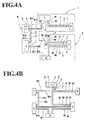
- Fig.4A shows partially-connected wire harnesses (abbreviation W/H) I, II and III, whilst Fig.4B shows entirely-connected wire harnesses W/H.
- W/H partially-connected wire harnesses
- Fig.4B shows entirely-connected wire harnesses W/H.
- fifteen electrical cables and their different color markings are respectively designated by references W1 to W15 and to .
- partially-connected wire harness I a first end of each of electrical cables W1, W2 and W3 is connected to connector A, whilst a second end thereof is connected to connector B. Accordingly, partially-connected wire harness I contain no dangling terminals (yet to be connected terminals). In the above wire harness, W1, W2 and W3 are painted with mutually different color units , and .
- W4 and W5 are both connected to connector and connector A in the same manner. They are therefore given mutually different color markings and .
- W6 and W7 are connected to the same connector at their first ends, and to the same connector E at their second ends. They are therefore given mutually different color markings and .
- W8 and W9 are connected to the same connector at their first ends, and to the same connector D at their second ends. They are therefore given mutually different color markings and .
- Connector thus contains two different color markings , two different color markings and two different color markings , respectively.
- W10 and W11 are connected to connector E at their first ends, whilst their second ends form dangling terminals T to be connected to connector D of partially-connected wire harness II.
- W12 and W13 are connected to connector E at their first ends, whilst their second ends are connected to connector F.
- W14 and W15 are connected to connector F at their first ends, whilst their second ends form dangling terminals T to be connected to connector A of partially-connected wire harness I.
- W10 and W11 are respectively connected to the same connectors D and E. They are therefore given mutually different color markings and .
- W12 and W13 are respectively connected to the same connectors E and F. They are therefore given mutually different color markings and .
- W14 and W15 are respectively connected to the same connectors F and A. They are therefore given mutually different color markings and .
- connector of partially-connected wire harness II forms a first connecting member (for prior connection), whilst connector A of partially-connected wire harness I forms a second connecting member (for subsequent connection).
- connector A (second connecting member) receives, for subsequent connections, the dangling terminals T of W4 and W5 from connector (first connecting member), and the dangling terminals T of W14 and W15 from connector F (first connecting member).
- the different color markings of W4 and W5 are respectively and .
- W14 and W15 may also be given different color markings and respectively.
- W4 and W5 of connector have a mutually different color marking, but the same as that of W14 and that of W15, respectively.
- the arrangement table for the second connecting member may contain columns designated e.g. I, II and III, as shown in Fig.5B.
- the dangling terminals of W4 and W5 from connector are first connected to the corresponding connector terminals (marked II in the arrangement table), and those of W14 and W15 from connector F are then connected to the corresponding connector terminals (marked III in the arrangement table). Connection errors can thus be avoided.
- the number of subsequent connections is less than that of prior connections. Accordingly, the number of different color markings for the subsequent connections may be less than the number of different color markings necessary to prevent connection errors caused during the prior connections.
- the number of distinguishing cable colors necessary for an instrument panel harness can be calculated on the basis of formula (I).
- the critical number of different color markings for all the electrical cables, wired e.g. in an automobile of type "X" currently produced in a large scale, is calculated as follows.
- the critical number of different color markings is 13, as in the case calculated on the basis of the instrument panel harness.
- identification codes "M” e.g. in silver color are spotted on the electrical cables W1 to W13 along the respective length direction at given intervals.
- the identification codes "M” are spotted at a later stage as a function of the type and thickness of insulator coatings, the diameter of a core wire aggregate and the size of electrical cables, as already mentioned. These are therefore not included in the cable color units within the meaning of the present invention.
- the connector 10 to be engaged with the electrical cables of instrument panel harness includes 14 poles (enclosures a, b, c, etc.) and one unused enclosure "i". All the other enclosures a, b, c, etc. can be inserted with W1 ⁇ W13 having different base colors.
- the number of 13 thus used as necessary distinguishing cable colors for an automobile is merely one third (1/3) of the number of commonly used different color markings i.e. 46. Further, the electrical cables with stripes are not used, so that the manufacturing costs for cables are drastically reduced.
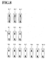
- Fig.8 shows a variant embodiment, in which 13 colored electrical cables are apportioned between 10 base color electrical cables W1 to W10, and three striped color electrical cables W1', W2' and W3'.
- the critical number of distinguishing cable colors is considered to be 13. However, it can be less than 13, as long as the same color cables are prevented from being erroneously inserted into the connector enclosures, and from subsequent misconnections.
- the critical number of different color markings is the maximum value. It may be less than 13, e.g. 11 or 10.
- the number of electrical cables contained in the critical unitary wire harness may be smaller, and the connectors 10 may contain fewer enclosures. Then, the critical number of distinguishing cable colors may be less than 13.
- the number of distinguishing cable colors used e.g. in an automobile can now be reduced to about one third, compared to the prior art approach which was considered to be necessary.
- the manufacturing costs of the cables can thus be greatly reduced.
- the entirety of the electrical cables wired e.g. in a car can be composed of the base colored cables without stripes. Consequently, especially in the case of small-sized cables, it is no longer necessary to distinguish the stripe color from the base color. The burden on workers during connecting operation is thus reduced, and misconnections due to erroneous recognition of cable colors can be avoided.
Landscapes
- Engineering & Computer Science (AREA)
- Manufacturing & Machinery (AREA)
- Insulated Conductors (AREA)
- Electric Cable Installation (AREA)
- Installation Of Indoor Wiring (AREA)
Abstract
Description


Claims (20)
- A method for determining a critical number of colors for the electrical cables (W) constituting a wire harness (W/H), the wire harness comprising a plurality of unitary wire harnesses (W/H-1 to W/H-6) to be engaged with a given number of connectors (10), each of the unitary wire harnesses (W/H-1 to W/H-6) containing a plurality of electrical cables (W) which respectively have a different color marking and comprise an electrical terminal (T) attached to at least one end thereof, whilst each of the connectors (10) includes a plurality of terminal receiving means (a, b, c, etc.) respectively adapted to receive a corresponding electrical terminal (T), so that each of the unitary wire harnesses (W/H-1 to W/H-6) can be engaged with a given number of connectors (10), characterized in that said method comprises the steps of:selecting a critical unitary wire harness among said plurality of unitary wire harnesses (W/H-1 to W/H-6);determining a critical number of different color markings to be contained in said critical unitary wire harness on the basis of the empirical formula:setting the total number of distinguishing cable colors necessary for each of said plurality of unitary wire harnesses (W/H-1 to W/H-6) to be equal to or less than said critical number of different color markings.
- The method according to claim 1, wherein said step of selecting a critical unitary wire harness comprises choosing a unitary wire harness (W/H-1 to W/H-6) containing either the greatest number of electrical cables (W) or the greatest number of connectors (10).
- The method according to claim 1 or 2, wherein said step of determining the critical number of different color markings comprises multiplying member R by a number equal to at least about 1.5, when C / B is less than 9.
- The method according to claim 3, wherein said number equal to at least about 1.5 is a number comprised between about 1.5 and about 2.0 inclusive .
- The method according to any one of claims 1 to 4, wherein said step of determining the critical number of different color markings comprises rounding up member R to the next highest integer, when said member R forms a decimal number.
- The method according to any one of claims 1 to 5, wherein said different color markings include a plain base color and/or a striped base color.
- The method according to claim 6, wherein said different color markings are composed solely of plain base colors.
- The method according to any one of claims 1 to 7, wherein said different color markings comprise 13 types of color at the maximum.
- The method according to any one of claims 1 to 8, wherein all of said different color markings used for a specific connector (10) are different from one another, or wherein said terminal receiving means (a, b, c, etc.) in a specific connector (10) are arranged such that either the same color markings are not placed in adjacent positions, or are placed in different sub-classes which are defined for said terminal receiving means (a, b, c, etc.).
- The method according to any one of claims 1 to 9, wherein said step of selecting a critical unitary wire harness comprises choosing a unitary wire harness containing at least 30 electrical cables.
- The method according to any one of claims 1 to 10, wherein said different color markings are further spotted with identification codes along the length of said electrical cables (W) at given intervals.
- A system for determining a critical number of colors for the electrical cables constituting a wire harness (W/H), the wire harness comprising a plurality of unitary wire harnesses (W/H-1 to W/H-6) to be engaged with a given number of connectors (10), each of the unitary wire harnesses (W/H-1 to W/H-6) containing a plurality of electrical cables (W) which respectively have a different color marking and comprise an electrical terminal (T) attached to at least one end thereof, whilst each of the connectors (10) includes a plurality of terminal receiving means (a, b, c, etc.) respectively adapted to receive a corresponding electrical terminal (T), so that each of the unitary wire harnesses (W/H-1 to W/H-6) can be engaged with a given number of connectors (10), characterized in that said system comprises:means for selecting a critical unitary wire harness among said plurality of unitary wire harnesses (W/H-1 to W/H-6);means for determining the critical number of different color markings to be contained in said critical unitary wire harness on the basis of the empirical formula:means for setting the total number of distinguishing cable colors necessary for each of said plurality of unitary wire harnesses (W/H-1 to W/H-6) to be equal to or less than said critical number of different color markings.
- The system according to claim 12, wherein said means for selecting a critical unitary wire harness comprises means for choosing a unitary wire harness (W/H-1 to W/H-6) containing either the greatest number of electrical cables (W) or the greatest number of connectors (10).
- The system according to claim 12 or 13, wherein said means for determining the critical number of different color markings comprises means for multiplying member R by a number equal to at least about 1.5, when C / B is less than 9.
- The system according to any one of claims 12 to 14, wherein said different color markings include a plain base color and/or a striped base color.
- The system according to any one of claims 12 to 15, wherein said different color markings comprise 13 types of color at the maximum.
- An automotive wire harness comprising a plurality of unitary wire harnesses (W/H-1 to W/H-6) to be engaged with a given number of connectors (10), each of the unitary wire harnesses (W/H-1 to W/H-6) containing a plurality of electrical cables which respectively have a different color and comprise an electrical terminal (T) attached to at least one end thereof, said unitary wire harnesses (W/H-1 to W/H-6) being adapted to be engaged with said connectors (10) including a plurality of terminal receiving means (a, b, c, etc.) for receiving a corresponding electrical terminal (T), characterized in that said automotive wire harness comprises:a critical unitary wire harness selected among said plurality of unitary wire harnesses (W/H-1 to W/H-6);a critical number of different color markings to be contained in said critical unitary wire harness, determined on the basis of the empirical formula:a necessary total number of distinguishing cable colors determined for each of said plurality of unitary wire harnesses (W/H-1 to W/H-6), which are equal to or less than said critical number of different color markings.
- The automotive wire harness according to claim 17, wherein said critical unitary wire harness comprises a unitary wire harness (W/H-1 to W/H-6) containing either the greatest number of electrical cables (W) or the greatest number of connectors (10).
- The automotive wire harness according to claim 17 or 18, wherein said critical number of different color markings comprises member R multiplied by a number equal to at least about 1.5, when C / B is less than 9.
- The automotive wire harness according to any one of claims 17 to 19, wherein said different color markings include a plain base color and/or a striped base color and comprise 13 types of color at the maximum.
Applications Claiming Priority (2)
| Application Number | Priority Date | Filing Date | Title |
|---|---|---|---|
| JP2001177630A JP4644977B2 (en) | 2001-06-12 | 2001-06-12 | Electric wire for automobile |
| JP2001177630 | 2001-06-12 |
Publications (2)
| Publication Number | Publication Date |
|---|---|
| EP1267364A2 true EP1267364A2 (en) | 2002-12-18 |
| EP1267364A3 EP1267364A3 (en) | 2003-12-03 |
Family
ID=19018439
Family Applications (1)
| Application Number | Title | Priority Date | Filing Date |
|---|---|---|---|
| EP02291453A Withdrawn EP1267364A3 (en) | 2001-06-12 | 2002-06-11 | Color arrangement of electrical cables e.g. for automobiles |
Country Status (3)
| Country | Link |
|---|---|
| US (1) | US6596942B2 (en) |
| EP (1) | EP1267364A3 (en) |
| JP (1) | JP4644977B2 (en) |
Cited By (1)
| Publication number | Priority date | Publication date | Assignee | Title |
|---|---|---|---|---|
| WO2013030517A1 (en) * | 2011-08-26 | 2013-03-07 | Clever Cabling Limited | Network patch cabling |
Families Citing this family (19)
| Publication number | Priority date | Publication date | Assignee | Title |
|---|---|---|---|---|
| EP1267286A3 (en) * | 2001-06-13 | 2003-02-12 | Sumitomo Wiring Systems, Ltd. | A wiring harness designing method, computer program and system |
| JP3941423B2 (en) * | 2001-06-15 | 2007-07-04 | トヨタ自動車株式会社 | Power control unit for vehicles |
| JP4295621B2 (en) * | 2001-11-27 | 2009-07-15 | 矢崎総業株式会社 | Order-made production method of wire harness and its production system |
| US20040099202A1 (en) * | 2002-11-22 | 2004-05-27 | Blake Jeffrey T. | Identification attachment for gauge |
| JP2004327372A (en) * | 2003-04-28 | 2004-11-18 | Yazaki Corp | Manufacturing method of wire harness and wire harness |
| JP2006066388A (en) * | 2004-07-30 | 2006-03-09 | Auto Network Gijutsu Kenkyusho:Kk | Automotive wire harness |
| US7854042B2 (en) * | 2007-05-16 | 2010-12-21 | Ron Richardson | Bundling device |
| US7745740B2 (en) * | 2007-12-04 | 2010-06-29 | Bridgeport Fittings, Inc. | Wire/cable identification device |
| JP5813285B2 (en) * | 2009-11-17 | 2015-11-17 | 東京鐵鋼株式会社 | Deformed steel bar |
| PH12012501703A1 (en) | 2010-03-02 | 2015-05-20 | Yazaki Corp | Wiring harness and manufacturing method thereof |
| JP2011188388A (en) * | 2010-03-10 | 2011-09-22 | Fujitsu Ltd | Portable device and connecting cable |
| GB201110508D0 (en) * | 2011-06-22 | 2011-08-03 | Smartwater Technology Ltd | A method for applying a marker to an electrical cable during manufacture |
| JP2014033905A (en) * | 2012-08-10 | 2014-02-24 | Fujishoji Co Ltd | Game machine |
| JP2015111536A (en) | 2013-11-01 | 2015-06-18 | 住友電装株式会社 | Electric wire with identification display |
| US20170025046A1 (en) * | 2015-07-21 | 2017-01-26 | Jeremy Butts | Electricians wire labelling system |
| WO2017022850A1 (en) * | 2015-08-05 | 2017-02-09 | 矢崎総業株式会社 | Wire harness system and wire harness |
| JP7063589B2 (en) * | 2017-12-04 | 2022-05-09 | 矢崎総業株式会社 | Circuit body for vehicles |
| US20190176721A1 (en) * | 2017-12-11 | 2019-06-13 | GM Global Technology Operations LLC | Vehicle wire harness with visual indicator for ease of assembly |
| US20260001693A1 (en) * | 2024-06-26 | 2026-01-01 | Genevieve Makinson | Cord retaining system, device and method |
Family Cites Families (21)
| Publication number | Priority date | Publication date | Assignee | Title |
|---|---|---|---|---|
| US3637037A (en) * | 1969-11-24 | 1972-01-25 | George D Doland | Auto theft protection system |
| GB1324563A (en) * | 1971-03-03 | 1973-07-25 | British Insulated Callenders | Multi-conductor electric cables |
| GB1556036A (en) * | 1975-10-30 | 1979-11-21 | Yazaki Corp | Process and apparatus for producing a wire-harness |
| EP0038861B1 (en) * | 1979-11-02 | 1985-05-15 | Mitsubishi Denki Kabushiki Kaisha | Wiring harness |
| US4424627A (en) * | 1980-08-04 | 1984-01-10 | Tarbox John W | Wiring harness construction means and method |
| JPS6124915A (en) * | 1984-07-12 | 1986-02-03 | Matsushita Electric Ind Co Ltd | liquid fuel combustion equipment |
| JPS6124915U (en) * | 1984-07-20 | 1986-02-14 | 古河電気工業株式会社 | Small diameter insulated wire for wire harness |
| JPH071645B2 (en) * | 1985-04-23 | 1995-01-11 | 矢崎総業株式会社 | Wire harness manufacturing method |
| US4711025A (en) * | 1986-05-05 | 1987-12-08 | Desanto Joseph J | Method and apparatus for forming electrical harnesses |
| DE3630619A1 (en) * | 1986-09-09 | 1988-03-17 | Standard Elektrik Lorenz Ag | OPTICAL OVERLAY RECEIVER |
| JPS6370623U (en) * | 1986-10-28 | 1988-05-12 | ||
| JPH01134808A (en) * | 1987-11-18 | 1989-05-26 | Nec Corp | Wire harness |
| WO1995005957A1 (en) * | 1993-08-24 | 1995-03-02 | United Technologies Automotive, Inc. | Wire harness assembly having color coded wires |
| US5470253A (en) * | 1994-10-03 | 1995-11-28 | Caterpillar Inc. | Engine wiring system |
| JP3028769B2 (en) * | 1996-02-28 | 2000-04-04 | 住友電装株式会社 | Wiring construction method of information line and wire harness for information line |
| US5862774A (en) * | 1996-07-11 | 1999-01-26 | Moss; Kurt A. | Electrical wire identification marking methods and systems |
| US5917151A (en) * | 1997-08-29 | 1999-06-29 | Ut Automotive Dearborn, Inc. | Multi-shot molds for manufacturing wire harnesses |
| JP3732664B2 (en) * | 1998-11-30 | 2006-01-05 | 矢崎総業株式会社 | Wire harness wiring design apparatus and method |
| US6291770B1 (en) * | 1999-05-14 | 2001-09-18 | Leoni Wiring Systems, Inc. | Wiring system and method therefor |
| US6447326B1 (en) * | 2000-08-09 | 2002-09-10 | Panduit Corp. | Patch cord connector |
| US6161278A (en) * | 1999-08-18 | 2000-12-19 | Lucent Technologies Inc. | Method for inserting wires into a telephone jack connector |
-
2001
- 2001-06-12 JP JP2001177630A patent/JP4644977B2/en not_active Expired - Fee Related
-
2002
- 2002-06-11 EP EP02291453A patent/EP1267364A3/en not_active Withdrawn
- 2002-06-11 US US10/166,120 patent/US6596942B2/en not_active Expired - Fee Related
Cited By (1)
| Publication number | Priority date | Publication date | Assignee | Title |
|---|---|---|---|---|
| WO2013030517A1 (en) * | 2011-08-26 | 2013-03-07 | Clever Cabling Limited | Network patch cabling |
Also Published As
| Publication number | Publication date |
|---|---|
| EP1267364A3 (en) | 2003-12-03 |
| JP2002367440A (en) | 2002-12-20 |
| JP4644977B2 (en) | 2011-03-09 |
| US20020189843A1 (en) | 2002-12-19 |
| US6596942B2 (en) | 2003-07-22 |
Similar Documents
| Publication | Publication Date | Title |
|---|---|---|
| US6596942B2 (en) | Color arrangement of electrical cables for vehicles | |
| US6702607B2 (en) | Wiring harness and manufacturing method of the same | |
| EP0605200B1 (en) | Press-contact connector assembly | |
| EP0734097B1 (en) | A circuit member and an electrical connection box | |
| US8513526B2 (en) | Wiring harness | |
| CN105684101B (en) | Electric wire with identification display | |
| EP1071162B1 (en) | Junction connector for wire harness | |
| DE102019212751B4 (en) | Wiring harness | |
| US9672960B2 (en) | Exterior member and electric wire wiring structure | |
| US20020079129A1 (en) | Cable harness arrangement | |
| JP2002204521A (en) | Method of assembling wire harness and structure of assembling part | |
| JPH09223412A (en) | Wire wiring structure | |
| EP0634819B1 (en) | Method and apparatus for mechanically and electrically coupling metal terminals in a housing | |
| JP3419150B2 (en) | Method of assembling automobile wire harness and automobile wire harness | |
| US5668415A (en) | Arrangement of harnesses in a vehicle | |
| JPH07335367A (en) | Method for preventing incorrect insertion of terminals and stopper used therefor | |
| JP2003061234A (en) | Method of setting arrangement pattern of automobile electric wires to connector and connection structure of electric wires to connector | |
| JP2003059353A (en) | Connector connection method and connection structure for automotive electric wires | |
| JPH1032913A (en) | Wiring assembly | |
| US6565378B1 (en) | Electrical connector terminal and housing | |
| EP4311728B1 (en) | Wire harness manufacturing method, wire harness, protective member assembly, and protective member | |
| JP2003061233A (en) | Connector connection structure and connection method for automotive electric wire | |
| DE102025143715A1 (en) | Cable set and method for bundling cables | |
| EP1098408A1 (en) | Method of installing a wiring system in premises and wiring system therefor | |
| JP2002343155A (en) | Routing time prediction method |
Legal Events
| Date | Code | Title | Description |
|---|---|---|---|
| PUAI | Public reference made under article 153(3) epc to a published international application that has entered the european phase |
Free format text: ORIGINAL CODE: 0009012 |
|
| AK | Designated contracting states |
Kind code of ref document: A2 Designated state(s): AT BE CH CY DE DK ES FI FR GB GR IE IT LI LU MC NL PT SE TR |
|
| AX | Request for extension of the european patent |
Free format text: AL;LT;LV;MK;RO;SI |
|
| PUAL | Search report despatched |
Free format text: ORIGINAL CODE: 0009013 |
|
| AK | Designated contracting states |
Kind code of ref document: A3 Designated state(s): AT BE CH CY DE DK ES FI FR GB GR IE IT LI LU MC NL PT SE TR |
|
| AX | Request for extension of the european patent |
Extension state: AL LT LV MK RO SI |
|
| 17P | Request for examination filed |
Effective date: 20040603 |
|
| AKX | Designation fees paid |
Designated state(s): DE FR GB |
|
| 17Q | First examination report despatched |
Effective date: 20090716 |
|
| STAA | Information on the status of an ep patent application or granted ep patent |
Free format text: STATUS: THE APPLICATION IS DEEMED TO BE WITHDRAWN |
|
| 18D | Application deemed to be withdrawn |
Effective date: 20160105 |