EP1267316A1 - Mechanical apparatus for demonstrating trigonometric functions, and drawing its graphs - Google Patents
Mechanical apparatus for demonstrating trigonometric functions, and drawing its graphs Download PDFInfo
- Publication number
- EP1267316A1 EP1267316A1 EP01810586A EP01810586A EP1267316A1 EP 1267316 A1 EP1267316 A1 EP 1267316A1 EP 01810586 A EP01810586 A EP 01810586A EP 01810586 A EP01810586 A EP 01810586A EP 1267316 A1 EP1267316 A1 EP 1267316A1
- Authority
- EP
- European Patent Office
- Prior art keywords
- circle
- bar
- functions
- demonstrating
- sin
- Prior art date
- Legal status (The legal status is an assumption and is not a legal conclusion. Google has not performed a legal analysis and makes no representation as to the accuracy of the status listed.)
- Granted
Links
- 238000010276 construction Methods 0.000 claims abstract description 10
- 239000011152 fibreglass Substances 0.000 claims description 6
- 229920003023 plastic Polymers 0.000 claims description 5
- 238000003825 pressing Methods 0.000 claims description 2
- 239000003086 colorant Substances 0.000 claims 3
- 239000000463 material Substances 0.000 claims 1
- 241000226657 Clarkia concinna Species 0.000 description 6
- 230000007423 decrease Effects 0.000 description 6
- 230000003247 decreasing effect Effects 0.000 description 6
- 238000013459 approach Methods 0.000 description 5
- 238000005259 measurement Methods 0.000 description 3
- 239000004033 plastic Substances 0.000 description 3
- 230000000007 visual effect Effects 0.000 description 3
- 238000004519 manufacturing process Methods 0.000 description 2
- 239000002184 metal Substances 0.000 description 2
- 238000000034 method Methods 0.000 description 2
- 238000004088 simulation Methods 0.000 description 2
- 230000001154 acute effect Effects 0.000 description 1
- 239000004744 fabric Substances 0.000 description 1
- 238000009958 sewing Methods 0.000 description 1
Images




Classifications
-
- G—PHYSICS
- G09—EDUCATION; CRYPTOGRAPHY; DISPLAY; ADVERTISING; SEALS
- G09B—EDUCATIONAL OR DEMONSTRATION APPLIANCES; APPLIANCES FOR TEACHING, OR COMMUNICATING WITH, THE BLIND, DEAF OR MUTE; MODELS; PLANETARIA; GLOBES; MAPS; DIAGRAMS
- G09B23/00—Models for scientific, medical, or mathematical purposes, e.g. full-sized devices for demonstration purposes
- G09B23/02—Models for scientific, medical, or mathematical purposes, e.g. full-sized devices for demonstration purposes for mathematics
- G09B23/04—Models for scientific, medical, or mathematical purposes, e.g. full-sized devices for demonstration purposes for mathematics for geometry, trigonometry, projection or perspective
Definitions
- the invention pertains to a sensible apparatus of hardware to be used as educational mean, to demonstrate and simplify many essential concepts in geometry and trigonometry, which are fundamentals in Mathematics taught at schools within secondary stage in all countries.
- the Invention is a mechanical apparatus for demonstrating Trigonometric Circle and identifying Trigonometric functions; Sin, Cos, Tan, Cot and to define the most important properties of these functions, and draw its graphs.
- the main objective of this invention is to solve the problem students face to understand some fundamentals in geometry, and to recognize the Trigonometric functions (Sin -Cos - Tan - Cot). Demonstrating the most important properties & features.
- the invention aims at explaining the concept of "Arc". Student can see and touch-by-hand unlimited number of arcs with different positive and negative values .
- the invention aims at showing the close relation between the Angle and the Arc. That provides a visual simulation to both Angle and the opposite Arc, which clears a lot of interference of students about the concept of Angle and concept of Arc.
- the invention aims at demonstrating the concept of (Radian) which is a measurement unit of Angles and Arcs depending on the radius of the circle .
- the invention aims at explaining the basic concepts of the trigonometric functions : Sin, Cos, Tan and Cot ; demonstrating their changes, their main properties, some of the most important relations.
- the invention aims at drawing the graphs of trigonometric functions : Sin , Cos , Tan and Cot.
- the invention is composed of two parts, the first quadrant part and the whole circle part .
- First quadrant part is for demonstrating all the four basic Trigonometric Functions but only in the first quadrant of the plane, i. e. the range of angle G is [0°, 90°], while the whole circle part is for demonstrating only the Sin and Cos Functions but in the whole plane, i. e. the range of angle G is [0°, 360°]. (90° means 90 degrees and so on).
- the bar working as radius to the said circle No.9 is numbered with 6 where the extended bar is numbered with 6a, a sliding segment in the first quadrant part is numbered with 7 while it is numbered in the whole circle part with 7a, and so on.
- FIG. 1 consists of transparent plastic board No.1, with two paths fixed on the said board : path No 2, and path No.3 perpendicular to No.2 .
- Piece No.7 slides on path No.2.
- Bar No.4 had fixed perpendicularly on said piece No.7 that the group (4, 7) moves as if it is one piece , so that the rigid bar No.4 (which is made of metal , plastic, wood ..etc) slides right and left , ever parallel to itself.
- D is a sliding knob combines the three bars (4, 5, 6) together. See (Fig. 4). D allows the two bars (4, 5) slid throw it, while it is connected to the edge of the bar No.6 through the hole at the said bar .
- That motion for the whole system is being easy and simple by help of easy sliding of segments (7 , 8) in its paths, easy sliding of bars (4 , 5) through the knob D and the easy rotation of bar No.6 around the center R of the circle 9
- Said motor No.21 has a gearbox for slowing the motion .
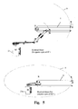
- the electrical motor 21 have movement period of 90°, and located behind the board No.1 of the first quadrant part of the invention , and motor 21a have movement period of 360° and located behind the board No.1 of the whole circle part. see (Fig. 5).
- Manufacturing of the invention would be done by several versions according to the size of the apparatus , starting with personal size , and school-size , up to huge sizes for Science museums and centers , in which high power motors is needed .
- Board No.1 of (Fig. 1) is all transparent except the area under the bar No.2 left to the bar No.3, that is the transparent area is up of the bar No.2, and right to the bar No.3.
- Said board No. 1 has gradients closed to the drawn line No.12 which denotes the X coordinate axis
- the said board has gradients closed to the drawn line No.13 which denotes the Y coordinate axis.
- the said gradients could be used for approximate reading of the Sin and Cos values of the angle G .
- Bar No.6 has back part parallel to the front part connected to it by a small curve, so the bar No.6 have the shape of the letter U . It rotates around the connecting point of its two parts, which path through the center R of the circle in such a way that the two legs of the bar No.6 appears parallel to each others as if they enfold the said board No.1 from its two sides.
- the said back part of bar No.6 has more than one task; it works as a base for moving the system because the electrical motors are connected to it. See (Fig. 5). Said back part also pulls out the yellow plate of G during the rotation of said back part around the center R of the circle 9 and finally it pulls out the fiber glass rope H during its rotation .
- the smaller circular section is a part of the shown surface bounded by bar No.2, bar No.6 and the arc G of the inner circle.
- the said section is composed of a plate, yellow colored now, made of plastic, metal, cloth, etc, located back to the board No.1, such as one of its edges is tied to the back part of the bar No.6 .
- the said part pulls the yellow plate through the motion of the system, so the angle DRC between bars 6 & 2 can be big or small according to the changeable position of the said bar No.6 .
- the unseened part of the said yellow plate is been hidden behind the non transparent part of the board No.1.
- the task of the said yellow circular section is to be as an indicator to the angle ⁇ DRC as it is familiar in Geometry.
- motor No.21 is connected to the back part of the said bar No.6 by two moving axes that cause the said back part of bar No.6 rotates around the center R of the said circle No.9 for a period of 90° .
- the two connection axes and the back part of said bar No.6 is being all in the same plane. while the front part of said bar No.6 is parallel to that plane, and body of said motor No.21 is perpendicular to the said plane.
- said motor enables moving the whole system, especially knob D, moving from C to E and returning back from E to C and so on.
- H denotes a piece of fiber glass rope , slides in a special curvilinear path, at the back side of the board No. 1, located beneath the circle No.9 , in which the part of the rope H appears as if it is a part of the said circle. See (Fig. 6).
- the whole circle part of (Fig. 11 & 12) has a similar fiber glass rope H, its edge is connected to the back part of bar No.6 by a special hook, representing different arcs, including the complete circle No.9 during the rotation of bar No.6 for 360°.
- a small lamp is connected to the other edge of the rope H , so the visual part H of the said rope will be luminous, sharp and beautiful representative to the said arc H .
- the rope H of (Fig. 1) is divided into equal parts by small colored signals.
- the arc between two next signals represents 10°.
- Gradients of rope H enable reading the measure of corresponding arc. Such reading provides approximate values, which is sufficient enough for educational purposes.
- class protractor could provide with better definite value for the arc H . (Which would be the value of the angle G at the same time).
- the box No.20 of (Fig. 7) is located at the back side of the board 1 of (Fig. 1).
- the ribbon No.10 which is similar to the sewing meter, is spirally curved and spout out of the said box, then extrude to the front surface through a hole at the position R in the said board No.1.
- the edge of the said ribbon No.10 is connected to the bar No.4 at the point B .
- Ribbon No.10 increases when bar 4 moves right, i.e. out of center R of the circle 9, while its length decreases when bar 4 moves left, i.e. close to the center R of the circle 9 .
- the said ribbon No.10 is colored green in present example .
- Ribbon No.11 of (Fig. 1) is exactly similar to said ribbon No.10, and colored red in present example .
- Ribbon No.11 increases when bar 5 moves up, i.e. out of center R of the circle, while its length decreases when bar 5 moves down, i.e. close to the center R of the circle 9 .
- the whole circle part of the invention has another indicators for Trigonometric functions, because the indicators similar to 10 and 11 of the said first quadrant part prevent the system of whole circle part moves completely.
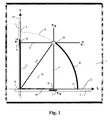
- Fig. 1 shows a simplified front view of the first quadrant part of the present invention , showing constructions and ribbons for Sin and Cos functions.
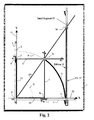
- Fig. 2 is the same as Fig. 1 showing constructions of Tan function, has been installed as a separate path and indicator, which could be installed or uninstalled as required .
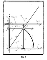
- Fig. 3 is the same as Fig. 1 showing constructions of Tan function, has been installed at the other position to represent the Cot function.
- Fig. 4 & 5 & 6 show sliding knob, electrical motors with gearboxes for moving the system and fiber glass rope representing an arc of the circle with its groove or furrow.
- Fig. 7 & 8 show ribbon with its box, gradients of ribbons for Sin or Cos, and for Tan or Cot functions.
- Fig. 9 shows the other indicator of Sin, Cos, Tan and Cot functions.
- Fig. 10 shows the indicator of Fig. 9 combined with path bar for representing Tan and Cot as it is shown in Fig. 2 & 3.
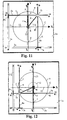
- Fig. 11 & 12 shows the Whole circle part of the present invention, showing constructions and indicator of Sin function, and the view of its application in two cases, first for G as an acute angle , and second for 180° ⁇ G ⁇ 270°.
- Fig.13 & 14 show a view of drawing system of the graph of the Sin function and the drawing pen .
- FIG. 1 shows part of the circle No.9 which is considered as the "trigonometric circle”.
- ribbon No. 10 represents Cos G
- ribbon No.11 represents Sin G .
- the invention demonstrates that the function Sin is an increasing function
- the invention demonstrates that the function Cos is a decreasing function
- FIG. 2 consists of component of (Fig. 1) with extra path No.14, segment No.15 sliding on said path, knob M connects the two bars (14, 6a) and allows bar 6a go through and slide inside.
- the bar No.14 could be installed and uninstalled to the said board No. 1 with front face down, in such a way that the segment No.15 and the said knob M are facing the said board No.1. This enables the system rotates with no obstruction, while the knob (M) is articulated to sliding segment (15) and allows bar (6a) slides through.
- the apparatus of the present invention could represents efficiently the tangent of the angles up to 70°, or maybe up to 80° for another version of the said apparatus, but it is very difficult to represent the tangent function for the angles approaching 90°.
- the present invention demonstrates that the tangent function is unlimited function, differing from Sin and Cos functions .
- the present invention demonstrates also that the tangent values are less than 1 for angles belongs to the interval (0°, 45°), and the values would be greater than 1 for angles belongs to the interval (45°, 90°).
- the tangent function is an increasing function
- bar No.14 with indicator as of (Fig. 10) could be installed at the horizontal position to represent Cot function. because it is well known in Mathematics that the length of tangent line represented by ribbon No.16 is the cotangent of angle G See triangle MRE (Fig. 3).
- the present invention demonstrates physically that the XY- plane is divided into four quadrants. "First quarter part" of the invention is for demonstrating the said concepts in the first quadrant.
- present invention demonstrates that Cos G appears with positive measures when point D is in the first and fourth quadrants , and appears with negative measures when point D is in the second and third quadrants .
- the present invention draws the graphs of the trigonometric functions .
- (Fig. 13) we see the part of the apparatus which draws the graph of the Sin function.
- the whole said system is underneath of the said bars 4a, 5a and 6.
- the cylinder No.22 is rounded by a roll of paper or plastic, etc., for drawing on it .
- Cylindrical wheel No.23 is fixed close to the line No.13.
- Cylindrical wheel No.24 is connected to electrical motor No.25 located behind the board 1a . When motor 25 rotates, it will cause rotating of wheel No.24, in which it pulls out the front part of the paper No.27 towards it, i.e. from right side to left side .
- Pen No.26 is connected to the bar No.5a at the position F, in fact little bit left of F, by a holder, in such a way that the said holder or base of the pen be at the middle of the said bar to allow the open part of knob D slides, not being obstructed by the said base of connection. See (Fig. 14).
- the said pen has a spring keeping it always pressing the paper No.27, in the same time the said spring allows pen 26 slides gently over the bar No.4a when it cross the point E from right to left, and cross the point J from left to right.
- the said pen draws the diameter EJ of the circle 9, starting from the center R then the point E, returning back to R, then J, then R again, and so on .
- the said pen will continue this harmonic motion as long as D still rotating on the circle.
- the invention clarifies the concept of Arc , that enables the student notice and see representations for infinite number of arcs ; how it and its measurements changes.
- Fig. 1 the blue shown arc denoted by H, with approximate value 60° .
- knob D By moving of knob D we could obtain other arcs that have the values 10°, 20°, 30°, 40° ...etc.
- the invention demonstrates that the arc depends on the existence of a definite circle, and that just knowing the length of an arc does not define it , and the circle in which the arc is taken as a part of it must be defined.
- the arc H has the same measure as like as the arc G of the inner small circle, despite of the variety of their length .
- the common value of the two arcs is about 60°.
- the invention demonstrates the concept of radian as a unit of measurement for angles and arcs .
Landscapes
- General Physics & Mathematics (AREA)
- Physics & Mathematics (AREA)
- Pure & Applied Mathematics (AREA)
- Computational Mathematics (AREA)
- Mathematical Analysis (AREA)
- Mathematical Optimization (AREA)
- Engineering & Computer Science (AREA)
- Mathematical Physics (AREA)
- Theoretical Computer Science (AREA)
- Business, Economics & Management (AREA)
- Geometry (AREA)
- Educational Administration (AREA)
- Educational Technology (AREA)
- Algebra (AREA)
- Drawing Aids And Blackboards (AREA)
- Displays For Variable Information Using Movable Means (AREA)
- Instructional Devices (AREA)
- Measuring Pulse, Heart Rate, Blood Pressure Or Blood Flow (AREA)
- Calculators And Similar Devices (AREA)
- Electrophonic Musical Instruments (AREA)
- Toys (AREA)
Abstract
Description
- The invention pertains to a sensible apparatus of hardware to be used as educational mean, to demonstrate and simplify many essential concepts in geometry and trigonometry, which are fundamentals in Mathematics taught at schools within secondary stage in all countries. The Invention is a mechanical apparatus for demonstrating Trigonometric Circle and identifying Trigonometric functions; Sin, Cos, Tan, Cot and to define the most important properties of these functions, and draw its graphs.
- It is known and common among all concerned in mathematics that the existing educational means of mathematics are absolutely nil or extremely rare especially for secondary-stage. The few trials which were done up to date to add some creations or inventions that simplify the theories of Math are all rounding about Geometry, whilst, the most of other subjects nothing exists and completely neglected.
- There is actual problem in this regard all over the world about the difficulties in teaching this subject and the difficulties that students face to understand and realize theoretical concepts and/or to work on the applied cases and problems. The problem is not limited to the lower classes, but extended to the higher education stages.
- It is easier to understand sensible ideas and concepts much more than understanding the pure theories. The invention of a sensible means to demonstrate those pure theories offers a great favor to make it easy for all students and for general studies.
- The efforts paid to have easy mathematics are insufficient and no comparison can be held with any other scientific subject (Physics, Geography, Biology or Chemistry). It is not fair to utilize mathematics in all sciences, and not to utilize other sciences in Mathematics especially the Mechanics; design and make demonstrating means to help and simplify math.
- The reason for that poor effort, might be the fear of this approach or the despondence to do something for the deeply pure concepts of Mathematics, or considering them difficult to simulate or resemble, despite this is may be true often, but not always. Such feeling could obstruct the creative mind to not even think of doing something in this important field.
- Throughout my long practical experience of Mathematics teaching and education, I came to pass this obstacle and could enter to blank field while had not been ever reached. I reached to several groups and subfamilies of creations could be classified in two wags: either by mathematical topics or by the technical foundations and technical and manufacturing principles they deponed on. Will start with one of the means from the second category (depending on the mechanical movement)
- The main objective of this invention is to solve the problem students face to understand some fundamentals in geometry, and to recognize the Trigonometric functions (Sin -Cos - Tan - Cot). Demonstrating the most important properties & features.
- The invention aims at explaining the concept of "Arc". Student can see and touch-by-hand unlimited number of arcs with different positive and negative values .
- The invention aims at showing the close relation between the Angle and the Arc. That provides a visual simulation to both Angle and the opposite Arc, which clears a lot of interference of students about the concept of Angle and concept of Arc.
- The invention aims at demonstrating the concept of (Radian) which is a measurement unit of Angles and Arcs depending on the radius of the circle .
- The invention aims at explaining the basic concepts of the trigonometric functions : Sin, Cos, Tan and Cot ; demonstrating their changes, their main properties, some of the most important relations. The invention aims at drawing the graphs of trigonometric functions : Sin , Cos , Tan and Cot.
- The invention is composed of two parts, the first quadrant part and the whole circle part . First quadrant part is for demonstrating all the four basic Trigonometric Functions but only in the first quadrant of the plane, i. e. the range of angle G is [0°, 90°], while the whole circle part is for demonstrating only the Sin and Cos Functions but in the whole plane, i. e. the range of angle G is [0°, 360°]. (90° means 90 degrees and so on).
- Items of one part numbered as like as that of the other part, sometimes adding the letter (a) to the number if the said item has some changes . Particularly, the bar working as radius to the said circle No.9 is numbered with 6 where the extended bar is numbered with 6a, a sliding segment in the first quadrant part is numbered with 7 while it is numbered in the whole circle part with 7a, and so on.
- (Fig. 1) consists of transparent plastic board No.1, with two paths fixed on the said board :
path No 2, and path No.3 perpendicular to No.2 . Piece No.7 slides on path No.2. Bar No.4 had fixed perpendicularly on said piece No.7 that the group (4, 7) moves as if it is one piece , so that the rigid bar No.4 (which is made of metal , plastic, wood ..etc) slides right and left , ever parallel to itself. - In the same way bar No.5 slides up and down, ever parallel to itself. Straight segment No.6 rotate around the fixed point R with fixed length RD, hence the path of the point D is circular , that is D moves on the
circle 9.
Thecircle 9 had been drawn on the board 1a as a blue dotted line, as well on board 1a of (Fig. 11 & 12). - D is a sliding knob combines the three bars (4, 5, 6) together. See (Fig. 4). D allows the two bars (4, 5) slid throw it, while it is connected to the edge of the bar No.6 through the hole at the said bar .
- Electrical motor No.21 of (Fig. 5) moves the system in (Fig. 1 & 2 & 3) when necessary as an alternative of manual moving , especially for designs of huge sizes for museums, big galleries .. etc. so the said knob D slides and changes its position , but always remains tied up to the circle No.9.
- That motion for the whole system is being easy and simple by help of easy sliding of segments (7 , 8) in its paths, easy sliding of bars (4 , 5) through the knob D and the easy rotation of bar No.6 around the center R of the
circle 9 Said motor No.21 has a gearbox for slowing the motion . - The
electrical motor 21 have movement period of 90°, and located behind the board No.1 of the first quadrant part of the invention , andmotor 21a have movement period of 360° and located behind the board No.1 of the whole circle part. see (Fig. 5). - Note : Manufacturing of the invention would be done by several versions according to the size of the apparatus , starting with personal size , and school-size , up to huge sizes for Science museums and centers , in which high power motors is needed .
- Board No.1 of (Fig. 1) is all transparent except the area under the bar No.2 left to the bar No.3, that is the transparent area is up of the bar No.2, and right to the bar No.3. Said board No. 1 has gradients closed to the drawn line No.12 which denotes the X coordinate axis , while the said board has gradients closed to the drawn line No.13 which denotes the Y coordinate axis. The said gradients could be used for approximate reading of the Sin and Cos values of the angle G .
- Bar No.6 has back part parallel to the front part connected to it by a small curve, so the bar No.6 have the shape of the letter U . It rotates around the connecting point of its two parts, which path through the center R of the circle in such a way that the two legs of the bar No.6 appears parallel to each others as if they enfold the said board No.1 from its two sides.
- The said back part of bar No.6 has more than one task; it works as a base for moving the system because the electrical motors are connected to it. See (Fig. 5). Said back part also pulls out the yellow plate of G during the rotation of said back part around the center R of the
circle 9 and finally it pulls out the fiber glass rope H during its rotation . - In (Fig. 1) the smaller circular section is a part of the shown surface bounded by bar No.2, bar No.6 and the arc G of the inner circle. The said section is composed of a plate, yellow colored now, made of plastic, metal, cloth, etc, located back to the board No.1, such as one of its edges is tied to the back part of the bar No.6 . The said part pulls the yellow plate through the motion of the system, so the angle DRC between
bars 6 & 2 can be big or small according to the changeable position of the said bar No.6 . The unseened part of the said yellow plate is been hidden behind the non transparent part of the board No.1. The task of the said yellow circular section is to be as an indicator to the angle < DRC as it is familiar in Geometry. - In (Fig. 5) motor No.21 is connected to the back part of the said bar No.6 by two moving axes that cause the said back part of bar No.6 rotates around the center R of the said circle No.9 for a period of 90° . The two connection axes and the back part of said bar No.6 is being all in the same plane. while the front part of said bar No.6 is parallel to that plane, and body of said motor No.21 is perpendicular to the said plane. Thus said motor enables moving the whole system, especially knob D, moving from C to E and returning back from E to C and so on.
- Motor No.21a of (Fig. 5) enables bar No.6 and hence the whole system , rotates around the center R of the circle No.9 for a complete cycle of 360°.
- When moving the system in (Fig. 1), the value of the angle G increases or decreases according to the direction of the movement. When the motion is counterclockwise , the value of angle G increases, when the motion is clockwise , the value of angle G decreases.
- Now H denotes a piece of fiber glass rope , slides in a special curvilinear path, at the back side of the board No. 1, located beneath the circle No.9 , in which the part of the rope H appears as if it is a part of the said circle. See (Fig. 6).
- The whole circle part of (Fig. 11 & 12) has a similar fiber glass rope H, its edge is connected to the back part of bar No.6 by a special hook, representing different arcs, including the complete circle No.9 during the rotation of bar No.6 for 360°. A small lamp is connected to the other edge of the rope H , so the visual part H of the said rope will be luminous, sharp and beautiful representative to the said arc H .
- When moving the system in (Fig. 1), such as the knob D moves counterclockwise , i.e. high - left direction, the back part of bar No.6 pulls out the edge of the rope H, and the said rope H remains tied up to the circle No.9. When the knob D moves back , i.e. clockwise direction, the rope H also moves back by help of the spring pulling it back as in (Fig. 7). So the rope H represents the arc opposite to the angle G . The said arc H has the same value as that of angle G . For example if the value of the angle G is 20°, then the value of the opposite arc H is also 20°, and so on. (We write : 20° for both).
- The rope H of (Fig. 1) is divided into equal parts by small colored signals. The arc between two next signals represents 10°. Gradients of rope H enable reading the measure of corresponding arc. Such reading provides approximate values, which is sufficient enough for educational purposes. Of course class protractor could provide with better definite value for the arc H . (Which would be the value of the angle G at the same time).
- The box No.20 of (Fig. 7) is located at the back side of the
board 1 of (Fig. 1). The ribbon No.10, which is similar to the sewing meter, is spirally curved and spout out of the said box, then extrude to the front surface through a hole at the position R in the said board No.1. Thus the edge of the said ribbon No.10 is connected to the bar No.4 at the point B . - Ribbon No.10 increases when
bar 4 moves right, i.e. out of center R of thecircle 9, while its length decreases whenbar 4 moves left, i.e. close to the center R of thecircle 9 . The said ribbon No.10 is colored green in present example . - Ribbon No.11 of (Fig. 1) is exactly similar to said ribbon No.10, and colored red in present example . Ribbon No.11 increases when
bar 5 moves up, i.e. out of center R of the circle, while its length decreases whenbar 5 moves down, i.e. close to the center R of thecircle 9 . - The whole circle part of the invention has another indicators for Trigonometric functions, because the indicators similar to 10 and 11 of the said first quadrant part prevent the system of whole circle part moves completely.
- In (Fig. 11) we see the indicator No. 11a of Sin function makes a bridge over the system with ribbon and small hook moving through the transparent tube, which has a long groove for the hook, and two basis outside the components of the system. See (Fig. 9). Each one of the said basis has protrusions for installing, either at the board No. I of (Fig. 2&3), or the board No.1a of (Fig. 11&12&13), in such a way that the
indicators ribbon 11a is connected by the hook to the holder (base) of the pen No.26. See (Fig. 14) . Whenbar 5a moves up and down, it pulls the saidribbon 11a connected to it , to be shown clearly throughout the said transparent plastic tube, indicating the Sin function . In the same way 10a indicates Cos function at the horizontal position . - Numerous other objects, features and advantages of the invention should now become apparent upon a reading of the following, in which
- Fig. 1 shows a simplified front view of the first quadrant part of the present invention , showing constructions and ribbons for Sin and Cos functions.
- Fig. 2 is the same as Fig. 1 showing constructions of Tan function, has been installed as a separate path and indicator, which could be installed or uninstalled as required .
- Fig. 3 is the same as Fig. 1 showing constructions of Tan function, has been installed at the other position to represent the Cot function.
- Fig. 4 & 5 & 6 show sliding knob, electrical motors with gearboxes for moving the system and fiber glass rope representing an arc of the circle with its groove or furrow.
- Fig. 7 & 8 show ribbon with its box, gradients of ribbons for Sin or Cos, and for Tan or Cot functions.
- Fig. 9 shows the other indicator of Sin, Cos, Tan and Cot functions.
Fig. 10 shows the indicator of Fig. 9 combined with path bar for representing Tan and Cot as it is shown in Fig. 2 & 3. - Fig. 11 & 12 shows the Whole circle part of the present invention, showing constructions and indicator of Sin function, and the view of its application in two cases, first for G as an acute angle , and second for 180° < G < 270°.
- Fig.13 & 14 show a view of drawing system of the graph of the Sin function and the drawing pen .
- (Fig. 1) shows part of the circle No.9 which is considered as the "trigonometric circle". (Fig. 11) shows the said trigonometric circle completely, with radius RC =1, straight line No.12 drawn on the board 1a as the X coordinate axis, and the straight line No.13 drawn on the board 1a as the Y coordinate axis. So the Coordinates of point D is the Sin and Cos of angle G . This means that ribbon No. 10 represents Cos G, and ribbon No.11 represents Sin G .
- As we had seen already , the length of each of the ribbons (10, 11) changes when the angle G changes because of changing position of the two bars (4, 5). This shows how is the present invention provides a visual simulation to the trigonometric circle, the angle G, the functions of Sin and Cos, and the way that the said angle and functions change.
- In (Fig. 1), we have seen already that moving of D up-left or counterclockwise from C to E, causes increasing both of value of angle G and length of ribbon No.11 at the same time . This will be much clear when we observe that moving of D clockwise from E to C, causes decreasing of both of value of angle G and length of ribbon No.11 at the same time . This means that both of G and Sin G increase together , and decrees together. So the invention demonstrates that the function Sin is an increasing function.
This fact could be emphasized by moving D up and down, and observing the two points (F, D) how it rise up together and swing down together . - As for Sin function: In (Fig. 1), we have seen already that moving of D up-left or counterclockwise from C to E, causes increasing of value of angle G but the length of ribbon No.10 decreases . So the invention demonstrates that the function Cos is decreasing function . This will be much clear when we observe that moving of D clockwise from E to C, causes decreasing of value of angle G but the length of ribbon No.10 increases . That means, angle G and Cos G are opposite to each other, when G increases the function Cos G is been decreased, and vice versa. So, the invention demonstrates that the function Cos is a decreasing function.
- This fact could be emphasized by moving D up and down, and observing the two points (B, D) going advance to the right side together and retreat to the left side together. Thus, the invention demonstrates the important mathematical concept of monotonic functions, practically by a physical, sensible, touchable and eye-noticed manner never been done at all.
- (Fig. 2) consists of component of (Fig. 1) with extra path No.14, segment No.15 sliding on said path, knob M connects the two bars (14, 6a) and allows
bar 6a go through and slide inside. The bar No.14 could be installed and uninstalled to the said board No. 1 with front face down, in such a way that the segment No.15 and the said knob M are facing the said board No.1. This enables the system rotates with no obstruction, while the knob (M) is articulated to sliding segment (15) and allows bar (6a) slides through. - At the same time the indicator of (Fig. 9) could be installed together with bar No. 14 to indicate the Tan function, in which the small hook be connected to the knob M . See (Fig 10). Of course M changes its position but ever tied up to bar No. 14.
- It is well known in Mathematics that the length oftangent line represented by ribbon No.16 is the tangent of angle G See triangle MRC (Fig. 2).The present invention provides physical representation for the trigonometric function Tan .
- When D moves close to point C , the length of ribbon No. 16 will be very small , so when D is coincident on C , the said ribbon will disappear . This means mathematically that : Tan 0° = 0.
- Angle 45° makes triangle MRC of (Fig. 2) an isosceles triangle, so length of ribbon No.16 is equal to the length of RC. So the invention clarifies that: Tan 45° = 1. When D is close to E , the length of ribbon No.16 is too big and huge , so the invention clarifies that tangent of right angle goes far away to infinity. Mathematically we write : Tan 90° = ?.
- Practically the apparatus of the present invention could represents efficiently the tangent of the angles up to 70°, or maybe up to 80° for another version of the said apparatus, but it is very difficult to represent the tangent function for the angles approaching 90°.
- When making gradient to bar No.14 the
value 1 is been marked as the correspondence to the angle 45°, and then the gradients 0.5, 1.5, .. etc. is added as a general indicator to the whole values. A special gradient 0.58 would be marked as an approximation to the tangent of angle 30°, being marked at the board No. with the actual value: ? 3 / 3. Another gradient 1.73 would be marked as an approximation to the tangent of angle 60°, being marked at the board No. with the actual value : ? 3 . See (Fig. 8). - The present invention demonstrates that the tangent function is unlimited function, differing from Sin and Cos functions . The present invention demonstrates also that the tangent values are less than 1 for angles belongs to the interval (0°, 45°), and the values would be greater than 1 for angles belongs to the interval (45°, 90°).
- As have seen before, moving the knob D of (Fig. 2), causes changing both of angle G and length of ribbon No. 16 as Tan G. Thus, the present invention enables student repeats moving said knob D up and down , observing with full open eyes and mind that both of angle G and Tan G increase together, and decrease together. This would make student well understand how the tangent function is an increasing function.
- As for Tan, bar No.14 with indicator as of (Fig. 10) could be installed at the horizontal position to represent Cot function. because it is well known in Mathematics that the length of tangent line represented by ribbon No.16 is the cotangent of angle G See triangle MRE (Fig. 3).
- Returning back to (Fig. 1), it is well known that the length of ribbon No.11 cold be zero, when the edge F approaches to the center R of the
circle 9. In the other hand the length of ribbon No.11 increases, but maximum value could approach is 1. So present invention demonstrates that maximum value of Sin G is 1. Mathematically We write : Max (Sin G)=1. This is happened when knob D approaches point E . - In (Fig. 11), when D moves crossing out
point 1, ribbon No. 11a changes the direction of its movement and extends down side . Its value reading would be negative in this case. See this position in (Fig. 12). When D takes the position J, the length of ribbon No. 11a would equal the radius of the circle with negative value, so the present invention demonstrates that: Min (Sin G) = -1 - The present invention demonstrates physically that the XY- plane is divided into four quadrants. "First quarter part" of the invention is for demonstrating the said concepts in the first quadrant.
- As we have seen before, red ribbon No.11 a appears with positive measures when point D is in the first or second quadrant, and appears with negative measures when point D is in the third or fourth quadrant . (Fig. 12). Thus Present invention demonstrates that the function Sin G represented by said ribbon No.11a takes its positive values in the first and second quadrants , while it takes its negative values in the third and fourth quadrants, as it is well known in mathematics.
- Similarly , present invention demonstrates that Cos G appears with positive measures when point D is in the first and fourth quadrants , and appears with negative measures when point D is in the second and third quadrants .
- Present invention demonstrates the following : (See (Fig. 11&12)) :
- When D at position C : G=0°, length of red ribbon = 0.
So : Sin 0° = 0. Similarly : Cos 0° = 1 .
When D at position E : G= 90° . Length of red ribbon = 1
So: Sin 90° = 1. Similarly : Cos 90° = 0 . - When D at position I : G=180°. Length of red ribbon = 0
So : Sin 180° = 0 . Similarly : Cos 180° = - 1 . - When D at position J : G= 270° . Length of red ribbon = -1
So : Sin 270° = - 1 . Similarly : Cos 270° = 0 . - When D at position C : G= 360° . Length of red ribbon = 0
So : Sin 360° = 0 . Similarly : Cos 360° = 1. - Sin 0° = Sin 360° = 0.
Cos 0° = Cos 360° = 1. -
- The present invention draws the graphs of the trigonometric functions . In (Fig. 13) we see the part of the apparatus which draws the graph of the Sin function. The whole said system is underneath of the said bars 4a, 5a and 6. The cylinder No.22 is rounded by a roll of paper or plastic, etc., for drawing on it . Cylindrical wheel No.23 is fixed close to the line No.13. Cylindrical wheel No.24 is connected to electrical motor No.25 located behind the board 1a . When motor 25 rotates, it will cause rotating of wheel No.24, in which it pulls out the front part of the paper No.27 towards it, i.e. from right side to left side .
- Pen No.26 is connected to the bar No.5a at the position F, in fact little bit left of F, by a holder, in such a way that the said holder or base of the pen be at the middle of the said bar to allow the open part of knob D slides, not being obstructed by the said base of connection. See (Fig. 14). The said pen has a spring keeping it always pressing the paper No.27, in the same time the said spring allows
pen 26 slides gently over the bar No.4a when it cross the point E from right to left, and cross the point J from left to right. - When switching on motor No.21 , it will start, causing knob D slides. If D moves up left, the
bar 5a will raise up pulling the said pen No.26 upside . When D continue sliding , exceeding point E , thebar 5a will start lowing down, pulling the pen No.26 down side . The said pen will continue moving downside till it reaches point J. When knob D exceeds point J right side , the said pen will start raising up again . - Thus the said pen draws the diameter EJ of the
circle 9, starting from the center R then the point E, returning back to R, then J, then R again, and so on . The said pen will continue this harmonic motion as long as D still rotating on the circle. - To draw the graph of Sin function, we switch on both of the two motors No.21 and No.25 at the same time . The regular motion of the two motors will cause regular motion of the paper, and regular motion of the pen No.26 on the said paper . The known graph of the Sin function will be drawn .
- To draw the graph of Cos function, similar steps could be done, by fixing another pen at the point B with another roll of paper pulling down from up to down side .
- To draw the graph of Tan function, similar steps could be done, by fixing another pen at the point M with more wider roll of paper . As angle G approaches 90° , the point M will go so far away that the graph drawn fitting the area of the paper would be good enough .
- The invention clarifies the concept of Arc , that enables the student notice and see representations for infinite number of arcs ; how it and its measurements changes. In (Fig. 1), the blue shown arc denoted by H, with approximate value 60° . By moving of knob D we could obtain other arcs that have the
values 10°, 20°, 30°, 40° ...etc. - The invention demonstrates that the arc depends on the existence of a definite circle, and that just knowing the length of an arc does not define it , and the circle in which the arc is taken as a part of it must be defined.
- In (Fig. 1), the arc H has the same measure as like as the arc G of the inner small circle, despite of the variety of their length . The common value of the two arcs is about 60°.
- The invention demonstrates the concept of radian as a unit of measurement for angles and arcs . By disconnecting the edge of rope H at the back of board 1a of (Fig. 11) pulling H toward center R of the
circle 9, then the length of the same part of the rope H would be equal to the radius of said circle . - When the same part of rope H slides in its path again close to the
circle 9, then the arc obtained is exactly one radian , because the length of the arc is equal to the radius of its circle .
Claims (10)
- Mechanical apparatus for demonstrating trigonometric circle and the Sin, Cos, Tan and Cot functions . and definition of its most important properties and drawing its graphs comprising : a board which had a circle and coordinate axes drawn on with origin at the center of the circle, a mechanical construction of rigid bars, sliding perpendiculars, rigid arcs and ribbons, together with the said circle and coordinate axes, wherein the said construction denote The trigonometric circle with point (D) moving on it, (B) as the projection of (D) on the X- axis, (F) as the projection of (D) on the Y-axis , (G) the angle corresponding to the point (D) ; ribbon (RB) represents Cos G, ribbon (RF) represents Sin G ; ribbon (CM) represents Tan G, ribbon (EM) represents Cot G, the said ribbons has deferent colors, the said coordinate axes has also other deferent colors, the projector lines has its own deferent colors too; the said mechanical constructions and components could be moved and slide by easy and smooth manner, causing changes in the angle (G), and in the lengths of the said ribbons, hence causing changes in the trigonometric functions, that help understanding and learning mathematical concepts , definitions, properties and how to draw the said function graphs.
- Mechanical apparatus for demonstrating trigonometric circle and functions as claimed in claim 1, wherein the rigid bars (2, 3, 14) are fixed on the said board (1) by clips or screws , wherein the said rigid bars has grooves that allow sliding of the small segments (7, 8, 15) by ball bearing , such as every one of said segments is a sliding base to a firmly connected perpendicular, thus bar (4) slides on the said board (1) right and left sides ever parallel to itself, because of the easy sliding of the connected segment (7) on its path throughout the groove in the bar (2), and so for bar (5) and segment (8).
- Mechanical apparatus for demonstrating trigonometric circle and functions as claimed in claim 1, wherein the edge of bar (6) has a telescopic extension towards outside of (D), so that the said extension encounters the bar (14) when it been installed for studying the Tan or Cot functions, knowing that (6) has fixed length to provide circular motion to the point (D), wherein the other side of bar (6) has back part for connecting each of the plate (G), the electrical motors and the rope (H) .
- Mechanical apparatus for demonstrating trigonometric circle and functions as claimed in claim 1, wherein there is an indicator to the angle (G) as a circular section plate well colored, located behind the said board (1). such as the said plate connected to the back-part of bar (6), in such a way that the said back-part pulls the said plate during its movement wherein the area of the said circular section increases with increasing of angle (G) and vice versa; at the same time the rope (H) is made of fiber glass, connected to the back part of bar (6) for representing the arc (CD) corresponding the same angle (G), either the angle (G) and the arc (H) belongs to the first quadrant of the plane , or the angle (G) and the arc (H) belongs to the second, third and fourth quadrant, including the complete circle (9) wherein a small lamp is connected to the other edge of said rope (H) to keep it luminous .
- Mechanical apparatus for demonstrating trigonometric circle and functions as claimed in claim 1, wherein sliding knobs (D) and (M) allow more than one rigid bar slide easily through it, thus knob (D) is articulated to the edge of bar (6) , in the same time the said knob allows the two bars (4, 5) slides through , while the knob (M) is articulated to sliding segment (15) and allows bar (6a) slides through , thus knob (D) moves on the circle (9) while the bars (4, 5) represent geometrical projectors of point (D) on the bars (2, 3), thus point (B) is the projection of (D) on bar (2) ; (F) is the projection of (D) on bar (3).
- Mechanical apparatus for demonstrating trigonometric circle and functions as claimed in claim 1 , wherein the ribbons (10, 11,16) represent (Sin G , Cos G , Tan G & Cot G ) respectively , wherein each of (10) and (11) rolled ribbon could be pulled out of a box located behind the board (1), while the inner edge of the said rolled ribbons pulled towards the center of the said box, wherein the edges of the ribbons (10, 11) raised up from a hole in the board (1) at the center (R) of the circle (9) ; wherein the said ribbons (10,11, 16) enable reading the approximate values of (Sin G , Cos G, Tan G, Cot G) through numbers and graduations fixated or printed on the said board (1) close to lines (12, 13) and location of bar (14).
- Mechanical apparatus for demonstrating trigonometric circle and functions as claimed in claim 1, wherein the indicator of Sin and Cos functions for the whole circle part of the present invention is composed of transparent plastic tube with each of ribbons (16) and (11a) pulled out of a box attached to transparent tube which makes a bridge over the system with said ribbon and small hook moving through the transparent tube, which has a long groove for the movement of the hook, and two basis outside the components of the system, each one of the said basis has protrusions for installing at the board (1) in such a way that it could be installed and uninstalled easily, wherein the edge of the said ribbon (16) is connected by the hook to the knob (M).
- Mechanical apparatus for demonstrating trigonometric circle and functions as claimed in claim 1, wherein the roll of paper or other drawing material is rotating around the axis (22) because the electrical motor (25) pulls paper from cylindrical axis (23) right side, hence pulling paper from the said roll on axis (22) left side .
- Mechanical apparatus for demonstrating trigonometric circle and functions as claimed in claim 1, wherein the pen (26) is connected to the bar (5a) at the position (F), has a spring keeping it always pressing down and perpendicular to the drawing paper ; thus the pen (26) as it raising up and lowing down it draws the diameter (EJ) of the circle (9), starting from the center (R) then the point (E), returning back to (R), then (J), then (R) again , and so on ; thus the said pen (26) will continue this vertical harmonic motion as long as (D) still rotating on the circle (9).
- Mechanical apparatus for demonstrating trigonometric circle and functions as claimed in claim 1, wherein electrical motor (21, 21a) having gearboxes for slowing the motion, with connection axes is for moving back part of bar No.6 either for 90° or 360°, hence moving knob (D) and the whole system with regular motion ; the motor (21a) moves knob (D) regularly on the said circle (9), so that the said pen (26) by its vertical harmonic motion , draws the graph of Sin function during the movement of the said paper (27).
Priority Applications (3)
| Application Number | Priority Date | Filing Date | Title |
|---|---|---|---|
| DE60137204T DE60137204D1 (en) | 2001-06-17 | 2001-06-17 | Device for demonstrating trigonometric functions and displaying their graphs |
| AT01810586T ATE419608T1 (en) | 2001-06-17 | 2001-06-17 | DEVICE FOR DEMONSTRATING TRIGONOMETRIC FUNCTIONS AND DISPLAYING THEIR GRAPHS |
| EP01810586A EP1267316B1 (en) | 2001-06-17 | 2001-06-17 | Mechanical apparatus for demonstrating trigonometric functions, and drawing its graphs |
Applications Claiming Priority (1)
| Application Number | Priority Date | Filing Date | Title |
|---|---|---|---|
| EP01810586A EP1267316B1 (en) | 2001-06-17 | 2001-06-17 | Mechanical apparatus for demonstrating trigonometric functions, and drawing its graphs |
Publications (2)
| Publication Number | Publication Date |
|---|---|
| EP1267316A1 true EP1267316A1 (en) | 2002-12-18 |
| EP1267316B1 EP1267316B1 (en) | 2008-12-31 |
Family
ID=8183971
Family Applications (1)
| Application Number | Title | Priority Date | Filing Date |
|---|---|---|---|
| EP01810586A Expired - Lifetime EP1267316B1 (en) | 2001-06-17 | 2001-06-17 | Mechanical apparatus for demonstrating trigonometric functions, and drawing its graphs |
Country Status (3)
| Country | Link |
|---|---|
| EP (1) | EP1267316B1 (en) |
| AT (1) | ATE419608T1 (en) |
| DE (1) | DE60137204D1 (en) |
Cited By (9)
| Publication number | Priority date | Publication date | Assignee | Title |
|---|---|---|---|---|
| CN105059023A (en) * | 2015-09-01 | 2015-11-18 | 南京工业职业技术学院 | Log function demonstration and image drawing device |
| CN105059021A (en) * | 2015-09-01 | 2015-11-18 | 南京工业职业技术学院 | Composite function demonstration and image rendering device |
| CN107886811A (en) * | 2017-12-20 | 2018-04-06 | 黑龙江建筑职业技术学院 | Higher mathematics rectangular coordinate system in space apparatus for demonstrating and application method |
| CN109147495A (en) * | 2018-09-27 | 2019-01-04 | 莆田学院 | The teaching demonstration device and application method for approaching sawtooth wave are gradually superimposed with sine wave |
| CN112086003A (en) * | 2020-06-23 | 2020-12-15 | 袁昊 | Mechanical transmission demonstration workbench |
| CN113380117A (en) * | 2021-04-14 | 2021-09-10 | 江苏省南通中等专业学校 | Higher mathematical function teaching demonstration instrument |
| WO2021139839A3 (en) * | 2021-04-09 | 2022-02-24 | 郑州航空工业管理学院 | Demonstration system for high-level mathematical parametric equations and polar coordinates equations |
| CN114822175A (en) * | 2022-05-25 | 2022-07-29 | 日照职业技术学院 | A kind of advanced mathematics surface demonstration teaching aid |
| WO2025080500A1 (en) * | 2023-10-10 | 2025-04-17 | Brady Richter | Mechanical apparatus for illustrating the relationship between angles and trigonometric functions |
Families Citing this family (1)
| Publication number | Priority date | Publication date | Assignee | Title |
|---|---|---|---|---|
| CN104332085B (en) * | 2014-11-25 | 2016-07-27 | 南京工业职业技术学院 | Anyway the positive cosecant function demonstration of cotangent and image rendering instrument |
Citations (2)
| Publication number | Priority date | Publication date | Assignee | Title |
|---|---|---|---|---|
| US3359654A (en) * | 1965-11-22 | 1967-12-26 | James M Boyte | Apparatus for demonstrating the variation of the trigonometric functions in a two dimensional system |
| JP2000089661A (en) * | 1998-09-16 | 2000-03-31 | Tokai Univ | Math teaching tools |
-
2001
- 2001-06-17 AT AT01810586T patent/ATE419608T1/en not_active IP Right Cessation
- 2001-06-17 EP EP01810586A patent/EP1267316B1/en not_active Expired - Lifetime
- 2001-06-17 DE DE60137204T patent/DE60137204D1/en not_active Expired - Fee Related
Patent Citations (2)
| Publication number | Priority date | Publication date | Assignee | Title |
|---|---|---|---|---|
| US3359654A (en) * | 1965-11-22 | 1967-12-26 | James M Boyte | Apparatus for demonstrating the variation of the trigonometric functions in a two dimensional system |
| JP2000089661A (en) * | 1998-09-16 | 2000-03-31 | Tokai Univ | Math teaching tools |
Non-Patent Citations (1)
| Title |
|---|
| PATENT ABSTRACTS OF JAPAN vol. 2000, no. 06 22 September 2000 (2000-09-22) * |
Cited By (11)
| Publication number | Priority date | Publication date | Assignee | Title |
|---|---|---|---|---|
| CN105059023A (en) * | 2015-09-01 | 2015-11-18 | 南京工业职业技术学院 | Log function demonstration and image drawing device |
| CN105059021A (en) * | 2015-09-01 | 2015-11-18 | 南京工业职业技术学院 | Composite function demonstration and image rendering device |
| CN105059021B (en) * | 2015-09-01 | 2016-11-30 | 南京工业职业技术学院 | Compound function demonstration and image plotting device |
| CN107886811A (en) * | 2017-12-20 | 2018-04-06 | 黑龙江建筑职业技术学院 | Higher mathematics rectangular coordinate system in space apparatus for demonstrating and application method |
| CN109147495A (en) * | 2018-09-27 | 2019-01-04 | 莆田学院 | The teaching demonstration device and application method for approaching sawtooth wave are gradually superimposed with sine wave |
| CN109147495B (en) * | 2018-09-27 | 2023-08-25 | 莆田学院 | A teaching demonstration device and method of using sine waves to successively superimpose and approximate sawtooth waves |
| CN112086003A (en) * | 2020-06-23 | 2020-12-15 | 袁昊 | Mechanical transmission demonstration workbench |
| WO2021139839A3 (en) * | 2021-04-09 | 2022-02-24 | 郑州航空工业管理学院 | Demonstration system for high-level mathematical parametric equations and polar coordinates equations |
| CN113380117A (en) * | 2021-04-14 | 2021-09-10 | 江苏省南通中等专业学校 | Higher mathematical function teaching demonstration instrument |
| CN114822175A (en) * | 2022-05-25 | 2022-07-29 | 日照职业技术学院 | A kind of advanced mathematics surface demonstration teaching aid |
| WO2025080500A1 (en) * | 2023-10-10 | 2025-04-17 | Brady Richter | Mechanical apparatus for illustrating the relationship between angles and trigonometric functions |
Also Published As
| Publication number | Publication date |
|---|---|
| ATE419608T1 (en) | 2009-01-15 |
| DE60137204D1 (en) | 2009-02-12 |
| EP1267316B1 (en) | 2008-12-31 |
Similar Documents
| Publication | Publication Date | Title |
|---|---|---|
| Francis et al. | A topological picturebook | |
| US5732474A (en) | Visual aid and manipulative for demonstrating geometric and trigonmetric functions | |
| EP1267316B1 (en) | Mechanical apparatus for demonstrating trigonometric functions, and drawing its graphs | |
| US6132217A (en) | Method and apparatus for teaching relationship of trigonometric functions between unit circle and rectangular coordinate system | |
| US9754511B2 (en) | Devices and methods for hands-on learning of mathematical concepts | |
| CN206884542U (en) | A kind of mathematics Multifunctional teaching aid | |
| CN104318823B (en) | The demonstration of arcsine cosine function and image rendering instrument | |
| CN201444362U (en) | Multifunctional combined set square | |
| CN210680213U (en) | High school mathematics plane geometry teaching demonstration ware | |
| CN206733888U (en) | One kind rotation hand propelled secondary modern school mathematics is given lessons with board of education instrument | |
| CN106004179B (en) | Variable element cardioid is demonstrated and helical line drawing instrument | |
| CN203305722U (en) | Multifunctional movable triangular ruler | |
| CN203242198U (en) | Multifunctional compass for teaching blackboard | |
| CN207466187U (en) | A kind of mathematics multi-fucntion combined ruler | |
| CN201886679U (en) | Optical physical teaching experiment device | |
| CN201483992U (en) | Multifunctional set square for teaching | |
| CN204020333U (en) | A kind of mathematics Ellipsograph of giving lessons | |
| CN203681085U (en) | Three-in-one shape teaching aid | |
| CN217506753U (en) | Combined teaching aid for plane geometry teaching | |
| CN202439437U (en) | Multifunctional classifier for angles | |
| CN203331653U (en) | Plane geometry teaching aid | |
| CN2541918Y (en) | Mathematical teaching aid | |
| CN208593211U (en) | A kind of mathematical angle MEASUREMENT TEACHING instrument | |
| CN210955704U (en) | Secant function definition demonstration and image synthesizer | |
| CN207517226U (en) | A kind of teaching aid of analysis corresponding angles, alternate interior angle |
Legal Events
| Date | Code | Title | Description |
|---|---|---|---|
| PUAI | Public reference made under article 153(3) epc to a published international application that has entered the european phase |
Free format text: ORIGINAL CODE: 0009012 |
|
| AK | Designated contracting states |
Kind code of ref document: A1 Designated state(s): AT BE CH CY DE DK ES FI FR GB GR IE IT LI LU MC NL PT SE TR |
|
| AX | Request for extension of the european patent |
Free format text: AL;LT;LV;MK;RO;SI |
|
| 17P | Request for examination filed |
Effective date: 20030430 |
|
| AKX | Designation fees paid |
Designated state(s): AT BE CH CY DE DK ES FI FR GB GR IE IT LI LU MC NL PT SE TR |
|
| 17Q | First examination report despatched |
Effective date: 20040702 |
|
| GRAP | Despatch of communication of intention to grant a patent |
Free format text: ORIGINAL CODE: EPIDOSNIGR1 |
|
| GRAS | Grant fee paid |
Free format text: ORIGINAL CODE: EPIDOSNIGR3 |
|
| GRAA | (expected) grant |
Free format text: ORIGINAL CODE: 0009210 |
|
| AK | Designated contracting states |
Kind code of ref document: B1 Designated state(s): AT BE CH CY DE DK ES FI FR GB GR IE IT LI LU MC NL PT SE TR |
|
| REG | Reference to a national code |
Ref country code: GB Ref legal event code: FG4D Ref country code: CH Ref legal event code: EP |
|
| REF | Corresponds to: |
Ref document number: 60137204 Country of ref document: DE Date of ref document: 20090212 Kind code of ref document: P |
|
| REG | Reference to a national code |
Ref country code: IE Ref legal event code: FG4D |
|
| PG25 | Lapsed in a contracting state [announced via postgrant information from national office to epo] |
Ref country code: NL Free format text: LAPSE BECAUSE OF FAILURE TO SUBMIT A TRANSLATION OF THE DESCRIPTION OR TO PAY THE FEE WITHIN THE PRESCRIBED TIME-LIMIT Effective date: 20081231 Ref country code: FI Free format text: LAPSE BECAUSE OF FAILURE TO SUBMIT A TRANSLATION OF THE DESCRIPTION OR TO PAY THE FEE WITHIN THE PRESCRIBED TIME-LIMIT Effective date: 20081231 |
|
| NLV1 | Nl: lapsed or annulled due to failure to fulfill the requirements of art. 29p and 29m of the patents act | ||
| PG25 | Lapsed in a contracting state [announced via postgrant information from national office to epo] |
Ref country code: BE Free format text: LAPSE BECAUSE OF FAILURE TO SUBMIT A TRANSLATION OF THE DESCRIPTION OR TO PAY THE FEE WITHIN THE PRESCRIBED TIME-LIMIT Effective date: 20081231 Ref country code: ES Free format text: LAPSE BECAUSE OF FAILURE TO SUBMIT A TRANSLATION OF THE DESCRIPTION OR TO PAY THE FEE WITHIN THE PRESCRIBED TIME-LIMIT Effective date: 20090411 |
|
| PG25 | Lapsed in a contracting state [announced via postgrant information from national office to epo] |
Ref country code: PT Free format text: LAPSE BECAUSE OF FAILURE TO SUBMIT A TRANSLATION OF THE DESCRIPTION OR TO PAY THE FEE WITHIN THE PRESCRIBED TIME-LIMIT Effective date: 20090601 Ref country code: SE Free format text: LAPSE BECAUSE OF FAILURE TO SUBMIT A TRANSLATION OF THE DESCRIPTION OR TO PAY THE FEE WITHIN THE PRESCRIBED TIME-LIMIT Effective date: 20090331 Ref country code: AT Free format text: LAPSE BECAUSE OF FAILURE TO SUBMIT A TRANSLATION OF THE DESCRIPTION OR TO PAY THE FEE WITHIN THE PRESCRIBED TIME-LIMIT Effective date: 20081231 |
|
| PG25 | Lapsed in a contracting state [announced via postgrant information from national office to epo] |
Ref country code: DK Free format text: LAPSE BECAUSE OF FAILURE TO SUBMIT A TRANSLATION OF THE DESCRIPTION OR TO PAY THE FEE WITHIN THE PRESCRIBED TIME-LIMIT Effective date: 20081231 |
|
| PLBE | No opposition filed within time limit |
Free format text: ORIGINAL CODE: 0009261 |
|
| STAA | Information on the status of an ep patent application or granted ep patent |
Free format text: STATUS: NO OPPOSITION FILED WITHIN TIME LIMIT |
|
| 26N | No opposition filed |
Effective date: 20091001 |
|
| PG25 | Lapsed in a contracting state [announced via postgrant information from national office to epo] |
Ref country code: MC Free format text: LAPSE BECAUSE OF NON-PAYMENT OF DUE FEES Effective date: 20090630 |
|
| REG | Reference to a national code |
Ref country code: CH Ref legal event code: PL |
|
| GBPC | Gb: european patent ceased through non-payment of renewal fee |
Effective date: 20090617 |
|
| REG | Reference to a national code |
Ref country code: FR Ref legal event code: ST Effective date: 20100226 |
|
| REG | Reference to a national code |
Ref country code: IE Ref legal event code: MM4A |
|
| PG25 | Lapsed in a contracting state [announced via postgrant information from national office to epo] |
Ref country code: FR Free format text: LAPSE BECAUSE OF NON-PAYMENT OF DUE FEES Effective date: 20090630 Ref country code: IE Free format text: LAPSE BECAUSE OF NON-PAYMENT OF DUE FEES Effective date: 20090617 Ref country code: LI Free format text: LAPSE BECAUSE OF NON-PAYMENT OF DUE FEES Effective date: 20090630 Ref country code: CH Free format text: LAPSE BECAUSE OF NON-PAYMENT OF DUE FEES Effective date: 20090630 |
|
| PG25 | Lapsed in a contracting state [announced via postgrant information from national office to epo] |
Ref country code: GB Free format text: LAPSE BECAUSE OF NON-PAYMENT OF DUE FEES Effective date: 20090617 |
|
| PG25 | Lapsed in a contracting state [announced via postgrant information from national office to epo] |
Ref country code: DE Free format text: LAPSE BECAUSE OF NON-PAYMENT OF DUE FEES Effective date: 20100101 |
|
| PG25 | Lapsed in a contracting state [announced via postgrant information from national office to epo] |
Ref country code: GR Free format text: LAPSE BECAUSE OF FAILURE TO SUBMIT A TRANSLATION OF THE DESCRIPTION OR TO PAY THE FEE WITHIN THE PRESCRIBED TIME-LIMIT Effective date: 20090401 |
|
| PG25 | Lapsed in a contracting state [announced via postgrant information from national office to epo] |
Ref country code: IT Free format text: LAPSE BECAUSE OF FAILURE TO SUBMIT A TRANSLATION OF THE DESCRIPTION OR TO PAY THE FEE WITHIN THE PRESCRIBED TIME-LIMIT Effective date: 20081231 |
|
| PG25 | Lapsed in a contracting state [announced via postgrant information from national office to epo] |
Ref country code: LU Free format text: LAPSE BECAUSE OF NON-PAYMENT OF DUE FEES Effective date: 20090617 |
|
| PG25 | Lapsed in a contracting state [announced via postgrant information from national office to epo] |
Ref country code: TR Free format text: LAPSE BECAUSE OF FAILURE TO SUBMIT A TRANSLATION OF THE DESCRIPTION OR TO PAY THE FEE WITHIN THE PRESCRIBED TIME-LIMIT Effective date: 20081231 |
|
| PG25 | Lapsed in a contracting state [announced via postgrant information from national office to epo] |
Ref country code: CY Free format text: LAPSE BECAUSE OF FAILURE TO SUBMIT A TRANSLATION OF THE DESCRIPTION OR TO PAY THE FEE WITHIN THE PRESCRIBED TIME-LIMIT Effective date: 20081231 |