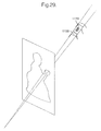
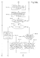
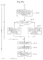
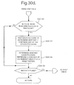
The present invention relates to computer processing to
generate a three-dimensional (3D) computer model of an
object, and more particularly to computer processing to
generate a 3D computer model by calculating the
intersections of polyhedra, each of which defines a
volume of 3D space containing at least part of the
object.
Many methods are known for generating a 3D computer model
of an object.
The known methods include "shape-from-silhouette"
methods, which generate a 3D computer model by processing
images of an object recorded at known positions and
orientations to back project the silhouette of the object
in each image to give a respective endless cone
containing the object and having its appex at the
position of the focal point of the camera when the image
was recorded. Each cone therefore constrains the volume
of 3D space occupied by the object, and the intersection
of the cones, which approximates the object, is
calculated.
Examples of shape-from-silhouette methods are described,
for example, in "Looking to build a model world:
automatic construction of static object models using
computer vision" by Illingworth and Hilton in Electronics
and Communication Engineering Journal, June 1998, pages
103-113, and "Automatic reconstruction of 3D objects
using a mobile camera" by Niem in Image and Vision
Computing 17 (1999) pages 125-134. The methods described
in both of these papers, however, calculate the
intersections of the silhouette cones to generate a
"volume representation" of the object made up of a
plurality of voxels (cuboids). More particularly, 3D
space is divided into voxels, and the voxels are tested
to determine which ones lie inside the volume defined by
the intersection of the silhouette cones. Voxels inside
the intersection volume are retained to define a volume
of voxels representing the object.
Such voxel techniques suffer from a number of problems,
however. In particular, the accuracy and resolution of
the resulting volume representation of the object is
determined by the size of the voxels into which the 3D
space is divided, and therefore reducing the size of the
voxels to increase the model resolution significantly
increases the number of voxels needing to be tested,
resulting in long processing times. In addition, the
voxel representation needs to be converted into a surface
model comprising a plurality of polygons because most
computer graphics rendering algorithms cannot render a
voxel model to generate an image for display to a user.
Such conversion requires further processing resources and
time, and can also reduce the resolution and accuracy of
the resulting computer model.
"A Volumetric Intersection Algorithm for 3d-Reconstruction
Using a Boundary-Representation" by Martin
Löhlein at http://i31www.ira.uka.de/diplomarbeiten/da_martin_loehlein/Reconstruction.html
discloses a shape-from-silhouette
method of generating a 3D computer model
which does not result in a voxel representation.
Instead, the intersections of the silhouette cones from
a plurality of images are calculated directly. More
particularly, the method starts with a cube containing
the object, and intersects it with the first silhouette
cone to give a first approximation of the object. This
approximation is then intersected with the next cone and
so on. To intersect a silhouette cone with an
approximation, the cone and the approximation are
projected into the image from which the cone was taken.
This reduces the cone to the 2d-polygon (silhouette) from
which it was made and the approximation from 3d-polygons
to 2d-polygons. The cone polygon is then intersected
with all the approximation's polygons using a
conventional algorithm for 2d-polygon intersection.
The method described in "A Volumetric Intersection
Algorithm for 3d-Reconstruction Using a Boundary-Representation"
is, however, inefficient in terms of
processing resources and processing time. The inventors
in the present application have realised that one
particular reason for this problem is the incremental
approach of intersecting a silhouette cone with a
representation to generate a refined representation
comprising connected 3D points defining planar faces,
then intersecting the refined representation with another
silhouette cone, and so on.
"An Algorithm for Determining the Intersection of Two
Simple Polyhedra" by M. Szilvasi-Nagy in Computer
Graphics Forum 3 (1984) pages 219-225 discloses a method
for calculating the intersection of two simple polyhedra,
such as a tetrahedron and a prism, by using a "plane-sweep
algorithm" to find all intersections of the edges
of each polyhedron with the faces of the other. While
this method is useful for two polyhedra, each having a
small number of faces, it would be extremely inefficient
in terms of computing resources and time for three or
more polyhedra and/or polyhedra with large numbers of
faces.
The present invention has been made with the above
problems in mind, and aims to address one or more of the
problems.
According to the present invention, there is provided a
computer processing method and apparatus for generating
a non-voxel representation of an object by intersecting
at least three polyhedra. The points of intersection of
the planar faces making up the polyhedra are calculated
and tested to determine which points correspond to object
points. Each object point is labelled with the planar
faces which meet thereat. Thereafter, when all object
points have been identified, connections between the
object points are specified in dependence upon the
labels.
In this way, by calculating all of the object points
before determining the connections therebetween, the
processing to determine the connections needs to be
performed only once, with consequential savings in
processing resources and/or time. This is made possible
by labelling each object point based on the planar faces
which intersect to generate the point, and calculating
which object points should be connected together using
their labels.
According to the present invention, there is also
provided a computer processing method and apparatus for
generating a non-voxel representation of an object by
intersecting a plurality of polyhedra. An initial 3D
volume in which the object lies is divided into parts,
and each part is tested against the polyhedra. If a
volume part is outside at least one polyhedron, it is
discarded because it cannot contain points representing
points on the object surface, otherwise the polyhedra
surfaces intersecting the volume are processed to
calculate the points of intersection thereof. A 3D
computer model comprising the calculated points of
intersection is therefore generated.
In this way, all intersections of the polyhedra surfaces
do not need to be calculated, because the processing
prevents intersections which cannot represent points on
the object from being calculated, resulting in savings
of processing resources and processing time.
Preferably, the processing is carried out in an even more
efficient way by repeatedly subdividing the initial
volume, and calculating the intersections of polyhedra
surfaces for a volume part only if the volume part is
intersected by a small number of polyhedra surfaces. By
way of explanation, in an embodiment, each intersection
comprises the intersection of three polyhedra surfaces.
Therefore, each respective combination of three surfaces
which intersect a volume part must be tested to determine
if they intersect, resulting in a considerable number of
calculations if a volume part is intersected by a large
number of polyhedra surfaces, with many of the
calculations being wasted because the point of
intersection does not represent a point on the object.
However, by repeatedly sub-dividing the initial volume,
large amounts of the volume can be discarded without
having to calculate any intersections, and by calculating
intersections only when a sufficiently small volume part
has been obtained that it is intersected by a small
number of polyhedra surfaces, the number of intersections
calculations which actually need to be performed are
minimised.
The present invention also provides a computer program
product, embodied for example as a storage device or
signal, including instructions for causing a programmable
processing apparatus to become operable to perform a
method as set out above or to become configured as an
apparatus as set out above.
Embodiments of the invention will now be described, by
way of example only, with reference to the accompanying
drawings in which:
First Embodiment
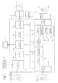
Referring to Figure 1, an embodiment of the invention
comprises a processing apparatus 2, such as a personal
computer, containing, in a conventional manner, one or
more processors, memories, graphics cards etc, together
with a display device 4, such as a conventional personal
computer monitor, user input devices 6, such as a
keyboard, mouse etc, a printer 8, and a display panel 10
comprising a flat panel having controllable pixels, such
as the PL400 manufactured by WACOM.
The processing apparatus 2 is programmed to operate in
accordance with programming instructions input, for
example, as data stored on a data storage medium, such
as disk 12, and/or as a signal 14 input to the processing
apparatus 2, for example from a remote database, by
transmission over a communication network (not shown)
such as the Internet or by transmission through the
atmosphere, and/or entered by a user via a user input
device 6 such as a keyboard.
As will be described in more detail below, the
programming instructions comprise instructions to cause
the processing apparatus 2 to become configured to
process input data defining a plurality of images of one
or more subject objects recorded at different positions
and orientations to calculate the positions and
orientations at which the input images were recorded, and
to use the calculated positions and orientations to
generate data defining a three-dimensional computer model
of the subject object(s). In this embodiment, the
subject object(s) is imaged on a calibration object (a
two-dimensional photographic mat in this embodiment)
which has a known pattern of features thereon, and the
positions and orientations at which the input images were
recorded are calculated by detecting the positions of the
features of the calibration object pattern in the images.
The 3D computer model of the subject object(s) is
generated using a novel and inventive polyhedra
intersection technique, in which the outline of the
subject object(s) in each image is divided into parts and
processing is performed to calculate 3D points
representing points on the surface of the subject object
by determining the intersections of the polyhedra defined
by the 3D projections of the outline parts. As will be
described in detail below, this processing is performed
in a particularly efficient way, in particular because
it avoids calculating intersections of faces within the
polyhedra which cannot result in 3D points on the subject
object surface.
When programmed by the programming instructions,
processing apparatus 2 can be thought of as being
configured as a number of functional units for performing
processing operations. Examples of such functional units
and their interconnections are shown in Figure 1. The
units and interconnections illustrated in Figure 1 are,
however, notional and are shown for illustration purposes
only to assist understanding; they do not necessarily
represent units and connections into which the processor,
memory etc of the processing apparatus 2 become
configured.
Referring to the functional units shown in Figure 1, a
central controller 20 is arranged to process inputs from
the user input devices 6, and also to provide control and
processing for the other functional units. Memory 24 is
provided for use by central controller 20 and the other
functional units.
Mat generator 30 is arranged to generate control signals
to control printer 8 or display panel 10 to print a
calibration pattern on a recording medium such as a piece
of paper to form a printed photographic mat, or to
display the calibration pattern on display panel 10 to
display a photographic mat. As will be described in more
detail below, the photographic mat comprises a
predetermined calibration pattern of features and the
object(s) for which a three-dimensional computer model
is to be generated is placed on the printed photographic
mat 34 or on the display panel 10 on which the
calibration pattern is displayed. Images of the object
and the calibration pattern are then recorded and input
to the processing apparatus 2. Mat generator 30 is
arranged to store data defining the calibration pattern
of features printed or displayed on the photographic mat
for use by the processing apparatus 2 in calculating the
positions and orientations at which the input images were
recorded. More particularly, in this embodiment, mat
generator 30 is arranged to store data defining the
pattern of features together with a coordinate system
relative to the pattern of features (which, in effect,
defines a reference position and orientation of the
calibration pattern), and processing apparatus 2 is
arranged to calculate the positions and orientations at
which the input images were recorded in the defined
coordinate system (and thus relative to the reference
position and orientation).
In this embodiment, the calibration pattern on the
photographic mat comprises spatial clusters of features
for example as described in PCT application GB00/04469
(the full contents of which are incorporated herein by
cross-reference) or any known pattern of features, such
as a pattern of coloured dots, with each dot having a
different hue/brightness combination so that each
respective dot is unique, for example as described in JP-A-9-170914,
a pattern of concentric circles connected by
radial line segments with known dimensions and position
markers in each quadrant, for example as described in
"Automatic Reconstruction of 3D Objects Using A Mobile
Camera" by Niem in Image and Vision Computing 17 (1999)
pages 125-134, or a pattern comprising concentric rings
with different diameters, for example as described in
"The Lumigraph" by Gortler et al in Computer Graphics
Proceedings, Annual Conference Series, 1996 ACM-0-89791-764-4/96/008.
In the remainder of the description, it will be assumed
that the calibration pattern is printed by printer 8 on
a recording medium (in this embodiment, a sheet of paper)
to generate a printed photographic mat 34, although, as
mentioned above, the calibration pattern could be
displayed on display panel 10 instead.
Input data store 40 is arranged to store input data input
to the processing apparatus 2 for example as data stored
on a storage device, such as disk 42, as a signal 44
transmitted to the processing apparatus 2, or using a
user input device 6. The input data defines a plurality
of images of one or more subject objects on the
photographic mat recorded at different positions and
orientations, and an input image showing the background
against which the object(s) was imaged together with part
of the photographic mat to show the background colour
thereof or a different object having the same colour as
the background colour of the mat. In addition, in this
embodiment, the input data also includes data defining
the intrinsic parameters of the camera which recorded the
images, that is, the aspect ratio, focal length,
principal point (the point at which the optical axis
intersects the imaging plane), first order radial
distortion coefficient, and skew angle (the angle between
the axes of the pixel grid; because the axes may not be
exactly orthogonal).
The input data defining the input images may be generated
for example by downloading pixel data from a digital
camera which recorded the images, or by scanning
photographs using a scanner (not shown). The input data
defining the intrinsic camera parameters may be input by
a user using a user input device 6.
Camera calculator 50 is arranged to process each input
image to detect the positions in the image of the
features in the calibration pattern of the photographic
mat and to calculate the position and orientation of the
camera when the input image was recorded.
Image data segmenter 60 is arranged to process each input
image to separate image data corresponding to the subject
object from other image data in the image.
Image segmentation editor 70 is operable, under user
control, to edit the segmented image data generated by
image data segmenter 60. As will be explained in more
detail below, this allows the user to correct an image
segmentation produced by image data segmenter 60, and in
particular for example to correct pixels mistakenly
determined by image data segmenter 60 to relate to the
subject object 210 (for example pixels relating to marks
or other features visible on the surface on which the
photographic mat 34 and subject object are placed for
imaging, pixels relating to shadows on the photographic
mat 34 and/or surface on which it is placed, and pixels
relating to a calibration feature on the photographic mat
34 which touches the outline of the subject object in the
input image have all been found to be mistakenly
classified during image data segmentation and to lead to
inaccuracies in the resulting 3D computer model if not
corrected).
Surface modeller 80 is arranged to process the segmented
image data produced by image data segmenter 60 and image
segmentation editor 70 and the data defining the
positions and orientations at which the images were
recorded generated by camera calculator 50, to generate
data defining a 3D computer model representing the actual
surfaces of the object(s) in the input images.
Surface modeller 80 comprises a silhouette approximator
82, a 3D point calculator 84, and a polygon generator 86.
Silhouette approximator 82 is arranged to process the
segmented image data generated by image data segmenter
60 and image segmentation editor 70 for each input image
to approximate the silhouette of the subject object(s)
in each image with straight line segments.
3D point calculator 84 is arranged to process the
straight line segments generated by silhouette
approximator 82 to calculate intersections of polygons
defined by the projection of the line segments into a
three-dimensional space. These intersections define 3D
points which are potentially on the surface of the
subject object(s). 3D point calculator 84 is arranged
to test the calculated 3D points to determine which ones
represent actual points in the surface object(s).
Polygon generator 86 is arranged to connect the 3D points
generated by 3D point calculator 84 to form a polygon
mesh representing the surface of the subject object(s).
More particularly, the intersections of the polygons
calculated by 3D point calculator 84 define 3D points on
the visual hull of the subject object(s), and accordingly
these 3D points are connected by polygon generator 86 so
that they form the vertices of the polygons in the
polygon mesh representing the surface of the subject
object(s). For this reason, hereinafter, the 3D points
calculated by 3D point calculator 84 will be referred to
as 3D vertices.
Surface texturer 90 is arranged to generate texture data
from the input image data for rendering onto the surface
model produced by surface modeller 80.
Display processor 110, under the control of central
controller 20, is arranged to display images and
instructions to a user via display device 4 during
processing to generate the 3D computer model. In
addition, under the control of central controller 20,
display processor 110 is also arranged to display images
of the 3D computer model of the object from a user-selected
viewpoint by processing the surface model data
generated by surface modeller 80 and rendering texture
data produced by surface texturer 90 onto the surface
model.
Output data store 120 is arranged to store the data
defining the surface model generated by surface modeller
80 and optionally the texture data generated by surface
texturer 90 as well. Central controller 20 is arranged
to control the output of data from output data store 120,
for example as data on a storage device, such as disk
122, and/or as a signal 124.
Referring to Figure 2, the printed photographic mat 34
is placed on a surface 200, and the subject object 210
for which a 3D computer model is to be generated is
placed on the photographic mat 34 so that the object 210
is surrounded by the features making up the calibration
pattern on the mat.
Preferably, the surface 200 is of a substantially uniform
colour, which, if possible, is different to any colour
in the subject object 210 so that, in input images, image
data relating to the subject object 210 can be accurately
distinguished from other image data during segmentation
processing by image data segmenter 60. However, if this
is not the case, for example if a mark 220 having a
colour the same as the colour in the subject object 210
appears on the surface 200 (and hence in input images),
processing can be performed in this embodiment to
accommodate this by allowing the user to edit
segmentation data produced by image data segmenter 60,
as will be described in more detail below.
Images of the object 210 and photographic mat 34 are
recorded at different positions and orientations to show
different parts of object 210 using a digital camera 230.
In this embodiment, data defining the images recorded by
camera 230 is input to processing apparatus 2 as a signal
44 along wire 232.
More particularly, in this embodiment, camera 230 remains
in a fixed position and photographic mat 34 with object
210 thereon is moved (translated) and rotated (for
example in the direction of arrow 240) on surface 200,
and photographs of the object 210 at different positions
and orientations relative to the camera 230 are recorded.
During the rotation and translation of the photographic
mat 34 on surface 200, the object 210 does not move
relative to the mat 34.
Figure 3 shows examples of images 300, 302, 304 and 306
defined in data input to processing apparatus 2 of the
object 210 and photographic mat 34 in different positions
and orientations relative to camera 230.
In this embodiment, following the recording and input of
images of object 210 and photographic mat 34, a further
image is recorded and input to processing apparatus 2.
This further image comprises a "background image", which
is an image of the surface 200 and an object having the
same colour as the paper on which photographic mat 34 is
printed. Such a background image may be recorded by
placing a blank sheet of paper having the same colour as
the sheet on which photographic mat 34 is recorded on
surface 200, or by turning the photographic mat 34 over
on surface 200 so that the pattern thereon is not visible
in the image.
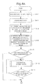
Figure 4 shows the processing operations performed by
processing apparatus 2 to process input data in this
embodiment.
Referring to Figure 4, at step S4-2, central controller
20 causes display processor 110 to display a message on
display device 4 requesting the user to input data for
processing.
At step S4-4, data input by the user in response to the
request at step S4-2 is stored in the input data store
40. More particularly, in this embodiment, the input
data comprises image data defining the images of the
object 210 and photographic mat 34 recorded at different
positions and orientations relative to the camera 230,
the "background image" showing the surface 200 on which
photographic mat 34 was placed to record the input images
together with an object having the same colour as the
recording material on which the calibration pattern of
photographic mat 34 is printed, and data defining the
intrinsic parameters of the camera 230 which recorded the
input images, that is the aspect ratio, focal length,
principal point (the point at which the optical axis
intersects the imaging plane), the first order radial
distortion coefficient, and the skew angle (the angle
between the axes of the pixel grid).
At step S4-6, camera calculator 50 processes the input
data stored at step S4-4 to determine the position and
orientation of the camera 230 relative to the
calibration pattern on the photographic mat 34 (and hence
relative to the object 210) for each input image. This
processing comprises, for each input image, detecting the
features in the image which make up the calibration
pattern on the photographic mat 34 and comparing the
features to the stored pattern for the photographic mat
to determine the position and orientation of the camera
230 relative to the mat. The processing performed by
camera calculator 50 at step S4-6 depends upon the
calibration pattern of features used on the photographic
mat 34. Accordingly, suitable processing is described,
for example, in co-pending PCT application GB00/04469,
JP-A-9-170914, "Automatic Reconstruction of 3D Objects
Using A Mobile Camera" by Niem in Image and Vision
Computing 17 (1999) pages 125-134 and "The Lumigraph" by
Gortler et al in Computer Graphics Proceedings, Annual
Conference Series, 1996 ACM-0-89791-764-4/96/008.
At step S4-8, image data segmenter 60 processes each
input image to segment image data representing the object
210 form image data representing the photographic mat 34
and the surface 200 on which the mat 34 is placed (step
S4-8 being a preliminary step in this embodiment to
generate data for use in the subsequent generation of a
3D computer model of the surface of object 210, as will
be described in more detail below).
Figure 5 shows the processing operations performed by
image data segmenter 60 at step S4-8.
Referring to Figure 5, at steps S5-2 to S5-10, image data
segmenter 60 builds a hash table of quantised values
representing the colours in the input images which
represent the photographic mat 34 and the background 200
but not the object 210 itself.
More particularly, at step S5-2, image data segmenter 60
reads the RBG data values for the next pixel in the
"background image" stored at step S4-4 in Figure 4 (that
is, the final image to be input to processing apparatus
2 which shows the surface 200 and an object having the
same colour as the material on which photographic mat 34
is printed).
At step S5-4,
image data segmenter 60 calculates a
quantised red (R) value, a quantised green (G) and a
quantised blue (B) value for the pixel in accordance with
the following equation:
q = (p + t/2) t
where:
At step S5-6, image data segmenter 60 combines the
quantised R, G and B values calculated at step S5-4 into
a "triple value" in a conventional manner.
At step S5-8, image data segmenter 60 applies a hashing
function to the quantised R, G and B values calculated
at step S5-4 to define a bin in a hash table, and adds
the "triple" value defined at step S5-6 to the defined
bin. More particularly, in this embodiment, image data
segmenter 60 applies the following hashing function to
the quantised R, G and B values to define the bin in the
hash table:
h(q) = (qred&7)*2^6+ (qgreen&7)*2^3+(qblue&7)
That is, the bin in the hash table is defined by the
three least significant bits of each colour. This
function is chosen to try and spread out the data into
the available bins in the hash table, so that each bin
has only a small number of "triple" values. In this
embodiment, at step S5-8, the "triple" value is added to
the bin only if it does not already exist therein, so
that each "triple" value is added only once to the hash
table.
At step S5-10, image data segmenter 60 determines whether
there is another pixel in the background image. Steps
S5-2 to S5-10 are repeated until each pixel in the
"background" image has been processed in the manner
described above. As a result of this processing, a hash
table is generated containing values representing the
colours in the "background" image.
At steps S5-12 to S5-48, image data segmenter 60
considers each input image in turn and uses the hash
table to segment the data in the input image relating to
the photographic mat 34 and background from the data in
the input image relating to the object 210. The result
of the segmentation processing is displayed on display
device 4.
In this embodiment, the "background" image processed at
steps S5-2 to S5-10 to generate the hash table does not
show the calibration features on the photographic mat 34.
Accordingly, the segmentation performed at steps S5-12
to S5-48 does not distinguish pixel data relating to the
object 210 from pixel data relating to a calibration
feature on the photographic mat 34. Instead, in this
embodiment, the processing performed by surface modeller
80 to generate the 3D computer model of the surface of
object 210 is carried out in such a way that pixels
relating to a calibration feature on photographic mat 34
do not contribute to the surface model, as will be
described in more detail below.
At step S5-12, image data segmenter 60 considers the next
input image, and at step S5-14 reads the R, G and B
values for the next pixel in the input image (this being
the first pixel the first time step S5-14 is performed).
At step S5-16, image data segmenter 60 calculates a
quantised R value, a quantised G value and a quantised
B value for the pixel using equation (1) above.
At step S5-18, image data segmenter 60 combines the
quantised R, G and B values calculated at step S5-16 into
a "triple value".
At step S5-20, image data segmenter 60 applies a hashing
function in accordance with equation (2) above to the
quantised values calculated at step S5-16 to define a bin
in the hash table generated at steps S5-2 to 35-10.
At step S5-22, image data segmenter 60 reads the "triple"
values in the hash table bin defined at step S5-20, these
"triple" values representing the colours of the material
of the photographic mat 34 and the background surface
200.
At step S5-24, image data segmenter 60 determines whether
the "triple" value generated at step S5-18 of the pixel
in the input image currently being considered is the same
as any of the background "triple" values in the hash
table bin.
If it is determined at step S5-24 that the "triple" value
of the pixel is the same as a background "triple" value,
then, at step S5-26, it is determined that the pixel is
a background pixel and the value of the pixel is set to
"black".
On the other hand, if it is determined at step S5-24 that
the "triple" value of the pixel is not the same as any
"triple" value of the background, then, at step S5-28,
it is determined that the pixel is part of the object 210
and image data segmenter 60 sets the value of the pixel
to "white".
At step S5-30, image data segmenter 60 determines whether
there is another pixel in the input image. Steps S5-14
to S5-30 are repeated until each pixel in the input image
has been processed in the manner described above.
At steps S5-32 to S5-46, image data segmenter 60 performs
processing to correct any errors in the classification
of image pixels as background pixels or object pixels,
and to display the result of the segmentation processing
on display device 4.
More particularly, at step S5-32, image data segmenter
60 defines a circular mask for use as a median filter.
In this embodiment, the circular mask has a radius of 4
pixels.
At step S5-34, image data segmenter 60 performs
processing to place the centre of the mask defined at
step S5-32 at the centre of the next pixel in the binary
image generated at steps S5-26 and S5-28 (this being the
first pixel the first time step S5-34 is performed).
At step S5-36, image data segmenter 60 counts the number
of black pixels and the number of white pixels within the
mask.
At step S5-38, image data segmenter 60 determines whether
the number of white pixels within the mask is greater
than or equal to the number of black pixels within the
mask.
If it is determined at step S5-38 that the number of
white pixels is greater than or equal to the number of
black pixels, then, at step S5-40 image data segmenter
60 sets the value of the pixel on which the mask is
centred to white. On the other hand, if it is determined
at step S5-38 that the number of black pixels is greater
than the number of white pixels then, at step S5-42,
image data segmenter 60 sets the value of the pixel on
which the mask is centred to black.
At step S5-44, display processor 110 displays on display
device 4 a reduced resolution version (a "thumb nail"
image) of the input image currently being processed and
displays in the thumb nail image the result of the
segmentation processing previously performed on the pixel
at steps S5-34 to S5-42. Thus, the thumb nail image is
changed incrementally to show the result of the
segmentation processing as each pixel in the input image
is processed. In this embodiment, display processor 110
displays the result of the segmentation processing in the
thumb nail image so that image data in the input image
which is determined to represent the background is
presented as a predetermined colour, for example blue,
in the thumb nail image.
As a result of displaying the thumb nail image in this
way, the user sees which parts of the input image have
been processed and the result of the segmentation
processing, and hence can determine whether any amendment
is necessary.
At step S5-46, image data segmenter 60 determines whether
there is another pixel in the binary image, and steps S5-34
to S5-46 are repeated until each pixel has been
processed in the manner described above.
At step S5-48, image data segmenter 60 determines whether
there is another input image to be processed. Steps S5-12
to S5-48 are repeated until each input image has been
processed in the manner described above.
Referring again to Figure 4, at step S4-10, central
controller 20 determines whether a signal has been
received from a user via a user input device 6 indicating
that the user wishes to amend an image segmentation
generated at step S4-8 (this signal being generated by
the user in this embodiment by pointing and clicking on
the thumb nail image displayed on display device 4
corresponding to the segmentation which it is desired to
amend).
If it is determined at step S4-10 that an image
segmentation is to be changed then, at step S4-12, image
segmentation editor 70 amends the segmentation selected
by the user at step S4-10 in accordance with user input
instructions.
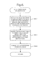
Figure 6 shows the processing operations performed by
image segmentation editor 70 during the interactive
amendment of an image segmentation at step S4-12.
Referring to Figure 6, at step S6-2, image segmentation
editor 70 causes display processor 110 to display the
image segmentation selected by the user at step S4-10 (by
pointing and clicking on the corresponding thumb nail
image) on display device 4 for editing. More
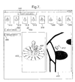
particularly, referring the Figure 7, in this embodiment,
the image segmentation 318 selected by the user at step
S4-10 from all of the displayed thumb nail images 310-324
is displayed in a window 400 in a form larger than that
in the thumb nail image. In this embodiment, the image
segmentation displayed in window 400 has the same number
of pixels as the input image which was processed to
generate the segmentation. In addition, the border of
the thumb nail image selected by the user (thumb nail
image 318 in the example of Figure 7) is highlighted, or
the thumb nail image is otherwise distinguished from the
other thumb nail images, to indicate that this is the
segmentation displayed in enlarged form for editing.
Also at step S6-2, image segmentation editor 70 causes
display processor 110 to display a window 402 moveable
by the user over the displayed image segmentation within
window 400. In addition, image segmentation editor 70
causes display processor 110 to display a further window
410 in which the part of the image segmentation contained
in window 402 is shown in magnified form so that the user
can see which pixels were determined by the image data
segmenter 60 at step S4-8 to belong to the object 210 or
to features on the photographic mat 34 and which pixels
were determined to be background pixels.
At step S6-4, image segmentation editor 70 changes the
pixels displayed in window 410 from background pixels to
object pixels (that is, pixels representing object 210
or features on the photographic mat 34) and/or changes
object pixels to background pixels in accordance with
user instructions. More particularly, for editing
purposes, image segmentation editor 70 causes display
processor 110 to display a pointer 412 which, in this
embodiment, has the form of a brush, which the user can
move using a user input device 6 such as a mouse to
designate pixels to be changed in window 410. In this
embodiment, each pixel which the user touches with the
pointer 412 changes to an object pixel if it was
previously a background pixel or changes to a background
pixel if it was previously an object pixel. In this
embodiment, the segmentation editor 70 causes display
processor 110 to display a user-selectable button 350,
the selection of which causes pointer 412 to become wider
(so that more pixels can be designated at the same time
thereby enabling large areas in window 410 to be changed
quickly) and a user-selectable button 360, the selection
of which causes the pointer 412 to become narrower.
By performing processing in this way, the user is, for
example, able to edit a segmentation generated by image
data segmenter 60 to designate as background pixels any
pixels mistakenly determined by image data segmenter 60
to relate to the subject object 210 (for example pixel
data relating to the mark 220 on surface 200 which would
not be separated from image data relating to subject
object 210 by image data segmenter 60 if it has the same
colour as a colour in subject object 210) and/or to
designate as background pixels relating to each
calibration feature on the photographic mat 34 which
touches the outline of the subject object 210 in an image
segmentation (as shown in the example of Figure 7) which,
if not corrected, have been found to cause errors in the
three-dimensional computer model of the subject object
subsequently generated by surface modeller 80.
Similarly, the user is able to designate as background
pixels relating to shadows on the photographic mat 34
and/or surface 200 which have mistakenly been determined
by image data segmenter 60 to be pixels relating to the
subject object 210.
At step S6-6, after the user has finished editing the
segmentation currently displayed (by pointing and
clicking on a different thumb nail image 310-324 or by
pointing and clicking on the "start processing" button
340), display processor 110 changes the displayed thumb
nail image corresponding to the segmentation edited by
the user at step S6-4 (thumb nail image 318 in the
example of Figure 7) to show the changes to the image
segmentation made by the user at step S6-4.
Referring again to Figure 4, at step S4-14, image
segmentation editor 70 determines whether the user wishes
to make any further changes to an image segmentation,
that is, whether the user has pointed and clicked on a
further thumb nail image 310-324.
When it is determined at step S4-10 or step S4-14 that
no further changes are to be made to an image
segmentation (that is, the user has pointed and clicked
on the "start processing" button 340), then processing
proceeds to step S4-16.
At step S4-16, surface modeller 80 performs processing
to generate data defining a 3D computer model of the
surface of subject object 210.
Figure 8 shows the processing operations performed by
surface modeller 80 at step S4-16.
Referring to Figure 8, at step S8-2, silhouette
approximator 82 processes the segmented image data
previously generated by image data segmenter 60 at step
S4-8 and image segmentation editor 70 at step S4-12 to
approximate the silhouette (that is, the outline) of the
subject object in each input image with straight lines
and to assign a unique label to each straight line. In
this embodiment, to approximate the subject object
silhouette in each image with straight lines, silhouette
approximator 82 performs processing in a conventional
manner, for example as described in "Dynamic Strip
Algorithm in Curve Fitting" by M.K. Leung and Y.H. Yang
in Computer Vision Graphics and Image Processing 51(2):
145-165, Aug 1990.
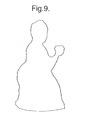
As a result of performing the processing at step S8-2,
the silhouette of the subject object in each image is
approximated by a plurality of connected straight lines,
as illustrated in Figure 9, which shows an approximation
of the object silhouette resulting from processing of
input image 302 in Figure 3. It should be noted,
however, that in the example of Figure 9 (and in all
subsequent Figures which show silhouettes), the number
of straight lines which are shown approximating the
silhouette may be far fewer than would actually be
generated in practice by silhouette approximator 82 at
step S8-2.
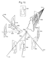
Referring to Figure 10, at this stage in the processing,
the silhouette 500-514 in each input image has been
approximated by straight line segments, and the position
and orientation of each silhouette in three-dimensional
space is known as a result of the calculations performed
at step S4-6 by camera calculator 50 to determine the
position and orientation of each input image (each
silhouette 500-514 lying in the two-dimensional plane of
an input image). In addition, the position of the focal
point of the camera 230 in three-dimensional space is
known for each input image as a result of the
calculations performed by camera calculator 50 at step
S4-6.
Each silhouette defines, together with the focal point
515-519 of the camera 230 which recorded the image in
which the silhouette is situated, an infinite cone in
three-dimensional space which touches the surface of the
subject object 210 at (as yet unknown) points in the
three-dimensional space (because the silhouette defines
the outline of the object surface in the image). This
is illustrated in Figure 10 for silhouette 502, which,
together with focal point position 515, defines cone 520.
The cross-section of the cone is the same shape as the
silhouette, and each cone is therefore made up of a
plurality of infinite planar triangles, each triangle
defined by lines passing through the end points of one
of the straight line segments approximating the
silhouette and the focal point of the camera 230 (each
planar triangle therefore being defined by the projection
of a silhouette straight line segment into 3D space).
Accordingly, each cone is an infinite polyhedron made up
of infinite triangular planar faces which all meet at the
focal point of the camera 230.
The intersection of the cones defined by all of the
silhouettes 500-514 defines the bounding surface of the
subject object in three-dimensional space. Consequently,
a three-dimensional computer model of the subject object
can be generated by calculating the intersection of all
of the cones, that is the visual hull.
In this embodiment, the intersection of the cones is
calculated by calculating the intersections of the planar
triangles making up each cone. Any 3D point at which
three of the planar triangles from at least two different
cones (that is, from at least two different silhouettes)
meet may define a vertex of the surface of the subject
object 210. The case where three triangles from
different respective silhouettes meet is illustrated in
Figure 10 for triangles 522, 524 and 526 which meet at
3D point 528. In the case where three triangles from two
silhouettes meet, the triangles which originate from the
same silhouette are defined by the 3D projection of
adjacent straight line segments in the silhouette (that
is, straight line segments which meet at a vertex point
in the silhouette). This is illustrated in Figure 10 for
planes 530, 532 and 534 which meet at 3D point 536
( planes 530 and 532 being defined by adjacent line
segments 531, 533 in silhouette 514 and point 536 lying
on the edge where planes 530 and 532 meet).
To ensure that the generated 3D computer model accurately
represents the surface of the subject object 210, each
intersection of triangles which results in a vertex of
the surface of the subject object needs to be computed.
As will be described in the third embodiment, this could
be achieved by testing each triangle defined by a line
segment in each silhouette against every triangle defined
by all of the other line segments in all of the other
silhouettes to generate a complete set of 3D points.
However, the number of computations necessary to
calculate 3D points representing vertices of the subject
object surface in this way is extremely large. More
particularly, if the total number of silhouettes is "m"
and the total number of straight lines in the silhouettes
is "n", then O(mn3) computations would be required. In
addition, much of the computation will be unnecessary
because many of the triangles tested will not intersect
(and hence will not lead to the generation of a 3D point)
and because 3D points which do not lie on the surface of
subject object 210 may be generated by chance
intersection of triangles (so that the 3D points will
need to be processed further to determine which ones
actually represent vertices for the model of the subject
object 210).
Consequently, in this embodiment, processing is performed
in a way which reduces the number of computations
necessary to calculate 3D points representing vertices
of the subject object surface.
Before describing this processing in detail, the
principles of the processing will be described.
More particularly, in this embodiment, processing is
performed to consider a volume of 3D space and to test
the volume to determine whether:
In this way, the processing ensures that all vertices of
the surface of the subject object 210 defined by the
intersection of the silhouette cones are calculated,
while avoiding unnecessary processing which does not lead
to the calculation of such a 3D point. In particular,
large volumes of 3D space can be discarded without
further calculation.
In this embodiment, the tests on a volume of 3D space to
determine whether it is to be discarded, subdivided or
a 3D point calculated are carried out by projecting the
3D volume into each two-dimensional image, and testing
the 2D projection of the 3D volume against the straight
lines making up each silhouette in the images (previously
generated at step S8-2). By performing the tests in 2D
in this way, the number of processing operations which
need to be performed to test the volume is reduced.
To determine whether a volume can be discarded because
the planar triangles therein cannot intersect at a 3D
point which represents a vertex of the surface of the
subject object 210, processing is performed to determine
whether the 3D point will lie within all of the cones
(polyhedra) defined by the silhouettes not contributing
a plane which intersects at the 3D point. Thus,
referring to the example shown in Figure 10, in the case
of planes 530, 532 and 534 processing is performed to
determine whether the 3D point 536 will lie within all
of the cones defined by silhouettes 500, 502, 504, 506,
508 and 510 (because these silhouettes do not define one
of the three planes intersecting at the 3D point 536).
In this embodiment, this processing is carried out by
testing the 2D projection of the volume in each image to
ensure that the 2D projection lies inside each
silhouette. That is, the tests are performed in 2D,
which reduces the processing operations which need to be
performed.
In this embodiment, when a 3D point is calculated, it is
subsequently tested to determine whether it represents
a vertex of the subject object 210. This is because a
3D point is calculated when a 3D volume is identified
which contains three planar triangles. However, the
three planar triangles may not actually intersect at a
3D point within the volume. Accordingly, a test is
carried out in this embodiment to determine whether the
calculated 3D point is within the identified volume.
The processing in this embodiment assumes that the
surface of the subject object is a simple polyhedron,
that is, there are no coincidences where more than three
planes meet at a single 3D point. In computer graphics
applications, this is a trivial restriction because this
situation can always be obtained, without affecting the
visual result, by adding a small amount of random noise
to the data defining the straight lines approximating
each silhouette, if necessary.
The processing performed in this embodiment to calculate
3D points representing vertices of the surface of subject
object 210 will now be described in detail.
Referring again to Figure 8, at step S8-4, silhouette
approximator 82 processes the data generated at step S8-2
for each silhouette to calculate a bounding box for each
straight line segment therein and to store the bounding
box data in a respective quad-tree structure for each
silhouette.
This processing is performed prior to the calculation of
any 3D vertex of the surface of the subject object 210
because, as will be explained later, the data resulting
from step S8-4 is used to determine which straight lines
in a silhouette do not need to be considered during
processing to calculate 3D points because the processing
of such straight lines cannot generate 3D vertices of the
surface of the subject object 210.
Figure 11 shows the processing operations performed by
silhouette approximator 82 at step S8-4.
Referring to Figure 11, at step S11-2, silhouette
approximator 82 considers the next silhouette to be
processed (this being the first silhouette the first time
step S11-2 is performed), and at step S11-4, calculates
a bounding box which has sides parallel to the image
sides for each straight line approximating the silhouette
which was generated at step S8-2.
More particularly, referring to Figure 12 by way of
example, silhouette approximator 82 calculates a bounding
box (indicated by the dotted lines in Figure 12) for each
straight line segment making up the silhouette such that
each side of a bounding box is parallel to a side of the
image - the straight line in the silhouette for which the
bounding box is calculated therefore being a diagonal of
the bounding box. In the case of a straight line in the
silhouette which is itself parallel to a side of the
image (that is, lines 550 and 552 in the example of
Figure 12) the bounding box is defined to have zero width
in the direction perpendicular to the line (although the
bounding boxes for lines 550 and 552 in the example of
Figure 12 are shown with a small width in order that the
bounding box can be seen in the Figure).
Silhouette approximator 82 stores the minimum and maximum
x values and the minimum and maximum y values of each
bounding box in the root node of a conventional quad-tree
(these values being indicated for bounding box 554 in the
example shown in Figure 12).
At step S11-6, silhouette approximator 82 determines the
range of x values and the range of y values stored in the
quad-tree node currently being considered (this being the
root node generated at step S11-4 the first time step
S11-6 is performed). That is, at step S11-6, silhouette
approximator 82 calculates the difference between the
smallest x value and the largest x value, and the
difference between the smallest y value and the largest
y value.
At step S11-8, silhouette approximator 82 creates two
child nodes in the quad-tree by splitting the node
currently being considered at the median of the values
in the coordinate determined at step S11-6 to have the
largest range. That is, if it is determined at step
S11-6 that the range of y values is larger than the range
of x values, silhouette approximator 82 splits the node
at the median of the y values, otherwise the split is
made at the median of the x values.
Thus, referring to the example shown in Figure 12,
because the range of y values is greater than the range
of x values, silhouette approximator 82 creates two child
nodes 560 and 562 by defining a line 564 perpendicular
to the y axis which passes through the median value of
the y values (that is, the median line segment end point
of the silhouette). In the example of Figure 12, there
are seventeen line end points, and accordingly the line
564 is defined to pass through the end point such that
there are eight line segment end points above the line
564 and eight line segment end points below the line 564.
If there is an even number of values, then in this
embodiment, silhouette approximator 82 defines line 564
to pass through the mid-point of the two values which
straddle the median.
At step S11-10, silhouette approximator 82 allocates
bounding boxes calculated at step S11-4 from the parent
node to be child nodes created at step S11-8.
More particularly, silhouette approximator 82 allocates
a bounding box to a child node if it lies wholly or
partially within the child node or if it touches the
child node. Thus, referring to the example shown in
Figure 12, each bounding box lying wholly above line 564
is allocated to child node 560, and each bounding box
lying wholly below line 564 is allocated to child node
562. Bounding boxes 570, 572 and 574 are allocated to
both child node 560 and child node 562 because each of
these bounding boxes lies partially in child node 560 and
partially in child node 562. Bounding boxes 576 and 578
are allocated to both child node 560 and child node 562
because each of these bounding boxes touches the line 564
defining the boundary of the child nodes 560 and 562.
At step S11-12, silhouette approximator 82 considers the
next child node, and at step S11-14, determines whether
the number of bounding boxes in the child node is the
same as the number of bounding boxes in the parent node.
If it is determined at step S11-14 that the number of
bounding boxes in the child node and the parent node is
the same, then further sub-division of the child node is
unnecessary because separation of the bounding boxes
between further child nodes would not be possible (each
further child note would contain all of the bounding
boxes from the parent). In addition, it is unnecessary
to keep the current child node considered at step S11-12
because it contains the same bounding boxes as its
parent, and it is also unnecessary to keep the other
child node created at step S11-8 (that is, the sibling
of the child node considered at step S11-12) because that
child node does not contain any bounding boxes (all of
the bounding boxes from the parent are in the current
child node considered at step S11-12).
Accordingly, when it is determined at step S11-14 that
the number of bounding boxes in the child node is the
same as the number in the parent node, processing
proceeds to step S11-16, at which silhouette approximator
82 deletes the child node considered at step S11-12 and
the sibling node created at step S11-8. Processing then
proceeds to step S11-20.
On the other hand, if it is determined at step S11-14
that the number of bounding boxes in the child node is
not the same as the number in the parent node, processing
proceeds to step S11-18, at which silhouette approximator
82 determines whether the number of bounding boxes in the
child node is equal to two.
If it is determined at step S11-18 that the number of
bounding boxes in the child node is equal to two, then
further sub-division of the child node is not performed
in this embodiment because a child node has already been
obtained with a sufficiently small number of bounding
boxes in it. Accordingly, processing proceeds to step
S11-20.
On the other hand, if it is determined at step S11-18
that the number of bounding boxes in the child node is
not equal to two, then processing returns to step S11-6.
Steps S11-6 to S11-18 are repeated to repeatedly create
and subdivide child nodes until it is determined at step
S11-14 that the number of bounding boxes in a child node
and its parent node are the same or until it is
determined at step S11-18 that a child node has been
generated containing two bounding boxes.
At step S11-20, silhouette approximator 82 determines
whether there is another child node to be processed, and
steps S11-12 to S11-20 are repeated until each child node
has been processed in the way described above.
At step S11-22, silhouette approximator 82 determines
whether there is another silhouette to be processed, and
steps S11-2 to S11-22 are repeated until each silhouette
has been processed in the way described above.
Referring again to Figure 8, at step S8-6, 3D point
calculator 84 performs processing to calculate 3D points
representing vertices of the surface of the subject
object 210.
Figure 13 shows the processing operations performed by
3D point calculator 84 at step S8-6.
Referring to Figure 13, at step S13-2, 3D point
calculator 84 defines a volume in 3D space in which the
subject object 210 lies, and hence in which all
calculated 3D points representing points on the object
surface will lie.
Referring to Figure 14a, in this embodiment, the start
volume defined by 3D point calculator 84 at step S13-2
comprises a cuboid 600 having vertical side faces and
horizontal top and bottom faces. The vertical side faces
are positioned so that they touch the edge of the
calibration pattern of features on the photographic mat
34 (and therefore wholly contain the subject object 210).
The position of the top face of the cuboid 600 is set at
a position defined by intersecting a line 610 from the
focal point 612 of the camera 230 through the top edge
of any one of the input images stored at step S4-4 with
a vertical line 614 through the centre of the
photographic mat 34. More particularly, the focal point
612 of the camera 230 and the top edge of an image are
known as a result of the position and orientation
calculations performed at step S4-16 and, by setting the
height of the top face to correspond to the point where
the line 610 intersects the vertical line 614 through the
centre of the photographic mat 34, the top face will
always be above the top of the subject object 210
(provided that the top of the subject object 210 is
visible in each input image). The position of the
horizontal base face of the cuboid 600 is set at a
position defined by intersecting a line 616 from the
focal point 612 of the camera 230 through the bottom edge
of any one of the input images stored at step S4-4 with
the vertical line 614 through the centre of the
photographic mat 34. This ensures that the base of the
cuboid 600 extends below the bottom of the subject object
210 (provided that the base of the subject object 210 is
visible in each input image).
In this embodiment, by imaging the subject object 210 as
illustrated in Figure 2 in which camera 230 is mounted
on a tripod in a fixed position and the photographic mat
34 with subject object 210 thereon is moved relative to
the camera, the camera 230 will always be outside the
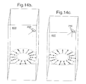
cuboid 600 when each image was recorded. However,
instead of moving the photographic mat 34 and subject
object 210 relative to stationary camera 230, it is
possible to move camera 230 to different positions and
orientations while leaving the photographic mat 34 and
subject object 210 stationary. In this case, as
illustrated in Figure 14b, the position of camera 230 may
be within cuboid 600 when an image is recorded to show
the top of the subject object 210 from an elevated
viewpoint. Since the processing to be performed by 3D
point calculator 84 in this embodiment projects the
cuboid 600 into the images recorded by camera 230 to
determine information about what is contained in the
projected volume, the cuboid 600 needs to lie completely
in front of the camera 230 for all recorded images.
Consequently, in this embodiment, 3D point calculator 84
tests the cuboid 600 against the camera positions and
orientations calculated at step S4-6 and, as illustrated
in Figure 14c, adjusts the cuboid 600 so that each corner
thereof is in front of every calculated camera position.
Referring again to Figure 13, at step S13-4, 3D point
calculator 84 adds the 3D volume defined at step S13-2
(that is, cuboid 600 in the example of Figures 14a, b and
c) to the top of a storage stack, and at step S13-6 pops
the next volume off the top of the stack (this being the
initial volume defined at step S13-2 the first time step
S13-6 is performed).
At step S13-8, 3D point calculator 84 determines the
state of the volume popped off the stack at step S13-6.
In this processing, 3D point calculator 84 determines
whether the volume popped off the stack at step S13-6
cannot contain any 3D vertex of the surface of the
subject object 210 (and hence can be discarded), whether
the volume needs to be subdivided because it may contain
more than one 3D vertex of the surface of the subject
object 210, or whether the volume contains planes which
may define just a single vertex of the subject object
surface, in which case the position of the 3D vertex can
be calculated and tested. In this embodiment, 3D point
calculator 84 performs these determinations by projecting
the 3D volume popped off the stack at step S13-6 into
each image and testing the resulting 2D projection
against the straight lines approximating each silhouette
previously calculated at step S8-2.
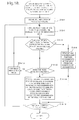
Figure 15 shows the processing operations performed by
3D point calculator 84 at step S13-8.
Referring to Figure 15, at step S15-2, 3D point
calculator 84 projects the corners of the volume popped
of the stack at step S13-6 into the two-dimensional
imaging plane of camera 230 for each imaging position and
orientation previously calculated at step S4-6, and
retains data defining the connectivity of the projected
corners.
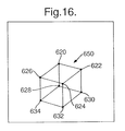
The result of this projection, which is illustrated in
Figure 16 for one image, is a 2D projection 650
comprising eight points 620-634 defining six enclosed
regions within the two-dimensional imaging plane (it
being noted that these regions may overlap). In the
example of Figure 16, the six regions defined by the
points are the regions defined by the groups of points
(620, 622, 624, 626), (620, 622, 630, 628), (622, 630,
632, 624), (624, 632, 634, 626), (626, 620, 628, 634),
and (628, 630, 632, 634).
At step S15-4, 3D point calculator 84 sets the value of
a counter nv to be 0. As will be explained below, this
counter represents the number of cameras on an "active
camera" list in which at least one "verified vertex"
(that is, a point at which two adjacent straight lines
in a silhouette meet which lies within the 2D projected
volume 650) has been detected. The list of active
cameras comprises a list of the silhouettes generated at
step S8-2 which are to be considered during processing.
Initially, the active camera list contains all of the
silhouettes but, as will be explained below, a silhouette
is deleted from the list when it is determined that the
silhouette encloses the 2D projected region 650 generated
at step S15-2. More particularly, because the silhouette
encloses the 2D projected region 650, it will therefore
enclose all projected child volumes, and so to prevent
the child volumes being generated and tested, the
silhouette is removed from the active camera list.
At step S15-6, 3D point calculator 84 sets the value of
a counter ne equal to 0. As will be explained below, the
value of this counter represents the number of cameras
on the active camera list in which at least one "verified
edge" (that is, a straight line from a silhouette lying
within the 2D projected volume 650) has been detected.
At step S15-8, 3D point calculator 84 sets the value of
a counter np equal to 0. As will be explained below, the
value of this counter represents the number of planar
triangles (that is, triangles defined by a straight line
segment - or "edge" - in a silhouette and the focal point
of camera 230, as described above with reference to
Figure 10) which intersect the volume popped off the
stack at step S13-6.
At step S15-10, 3D point calculator 84 sets the value of
a flag "eitherSubdivideOrDiscard" to "false".
In subsequent processing, 3D point calculator 84 performs
processing based on the relationship between the 2D
projected volume 650 resulting from step S15-2 and the
silhouette straight lines (edges) in each image resulting
from the processing at step S8-2 to determine whether the
3D volume popped off the stack at step S13-6 can be
discarded (because it does not contain any 3D vertices
of the surface of the subject object 210), requires sub-division
to consider smaller volumes (because it may
contain more than one 3D vertex of the object surface)
or it contains planes which may define a single vertex
of the object surface (in which case the position of the
vertex can be calculated and tested).
Before describing the specific processing steps carried
out by 3D point calculator 84, a description will be
given of the different relationships which may exist, and
which are tested for by 3D point calculator 84, between
the 2D projected volume 650 and the silhouette in an
image. In addition, a description will be given of how
3D point calculator 84 determines what processing to
perform on the volume popped off the stack at S13-6 based
on the determined relationship between the silhouette and
2D projected volume 650 for each image.
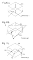
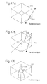
Figures 17a to 17h illustrate eight different
relationships which the silhouette and the 2D projected
volume 650 in an image may take and which are tested for
by 3D point calculator 84.
Referring to Figure 17a, in a first relationship, one,
and only one, vertex 700 of the silhouette (that is, a
point in the silhouette at which two consecutive straight
line segments making up the silhouette meet) lies within
one of the six two-dimensional regions of the projected
volume 650 (these regions being defined by the projected
corners of the volume as described previously).
Referring to Figure 17b, in a second relationship, one,
and only one, vertex 702 lies within the 2D projected
volume 650 and in addition at least one straight line
segment 704 not having a vertex in the projected volume
lies within the two-dimensional projected volume 650.
Referring to Figure 17c, in a third relationship, the
two-dimensional projected volume 650 contains more than
one silhouette vertex (in the example of Figure 17c, four
silhouette vertices 706, 708, 710 and 712 are shown,
although this third relationship is determined to exist
when any number of vertices greater than or equal to two
lie within the 2D projected volume 650).
Referring to Figure 17d, in a fourth relationship, one,
and only one, single straight line segment 714 of the
silhouette lies within the two-dimensional projected
volume 650 and neither of the vertices of the straight
line segment 714 lie in the projected volume 650.
Referring to Figure 17e, in a fifth relationship, the
two-dimensional projected volume 650 contains at least
two straight line segments 716, 718 of the silhouette
which do not have a vertex lying in the two-dimensional
projected volume 650.
Referring to Figure 17f, in a sixth relationship, the
silhouette 720 lies wholly inside the boundary of the
two-dimensional projected volume 650. This sixth
relationship is a special case of relationship 3
described above with reference to Figure 17c (the 2D
projected volume 650 contains at least one silhouette
vertex), and both relationship 3 and relationship 6
influence the decision about how to process the volume
popped off the stack at step S13-6 in the same way.
Accordingly, in this embodiment, relationship 6 is not
explicitly identified by 3D point calculator 84, and
instead only relationship 3 is detected. This has the
effect that processing is reduced because every vertex
of the silhouette is not tested to determine if it is in
the 2D projected volume 650 (which would be necessary if
relationship 6 was to be explicitly identified).
Referring to Figure 17g, in a seventh relationship, the
two-dimensional projected volume 650 lies wholly within
the silhouette 722.
Referring to Figure 17h, in an eighth relationship, the
silhouette 724 and the two-dimensional projected volume
650 do not overlap.
Based on the relationship between the 2D projected volume
650 and the silhouette in each image, 3D point calculator
84 sets the state of the volume popped off the stack at
step S13-6 (that is, determines how the volume is to be
processed) as set out in the following eight cases, which
are tested for by 3D point calculator 84. The eight
cases are listed below in order of priority, such that
any case higher in the list overrides any case lower in
the list and the processing to be performed on the volume
popped off the stack is determined based on the higher
priority case.
VOLUME STATE CASE A: Set state to "discard the
volume" if any image has relationship 8 (described above
with reference to Figure 17h) between the silhouette and
the 2D projected volume 650. In relationship 8, the 2D
projected volume 650 and the silhouette 724 do not
overlap, and accordingly any 3D points in the volume
popped off the stack at step S13-6 do not project to a
point on or within the silhouette 724 and consequently
cannot represent a vertex of the surface of subject
object 210. Accordingly, the volume popped off the stack
at step S13-6 is to be discarded.
VOLUME STATE CASE B: Set state to "calculate a 3D
point" if 3, and only 3, images have relationship 4
(described above with reference to Figure 17d) between
the silhouette and the 2D projected volume 650, and the
relationship in all of the other images is relationship
7 (described above with reference to Figure 17g).
As described previously with reference to Figure 10, a
3D vertex of the surface of subject object 210 is defined
by the intersection of three planar triangles, each from
a different silhouette, or by the intersection of two
triangles from the same silhouette with one triangle from
a further silhouette.
The case where three triangles from different silhouettes
intersect at a 3D point is identified in this embodiment
when three silhouettes having relationship 4 with the
projected volume 650 described above with reference to
Figure 17d are found and the relationship between the
silhouette in all other images and the projected volume
650 is relationship 7 described above with reference to
Figure 17g. More particularly, relationship 4 identifies
that there is only a single edge of a given silhouette
in the 2D projected volume 650 and accordingly three
silhouettes having this relationship with the projected
volume 650 identify three planar triangles (defined by
the three respective edges which intersect the 2D
projected volume 650) which may intersect at a 3D point
in the volume popped off the stack at step S13-6. In
addition, because the relationship between the silhouette
and the projected volume 650 in every other image is
relationship 7, the 3D point defined by the intersection
of the three planar triangles projects to a point inside
the silhouette in all of the images and accordingly
represents a vertex of the surface of the subject object
210 (provided that the 3D point actually lies in the
volume popped off the stack at step S13-6 and does not
lie outside this volume).
VOLUME STATE CASE C: Set state to "calculate a 3D
point" if 1 (and only 1) image has relationship 1
(described above with reference to Figure 17a) between
the silhouette and the 2D projected volume 650, 1 (and
only 1) image has relationship 4 (described above with
reference to Figure 17d) and the relationship in all of
the other images is relationship 7 (described above with
reference to Figure 17g).
This case C represents the case where two planar
triangles from the same silhouette and a planar triangle
from a different silhouette meet at a 3D point. More
particularly, the relationship described above with
reference to Figure 17a, in which only a single
silhouette vertex is present in the 2D projected volume
650, defines the two planar triangles from the same
silhouette which meet at the 3D point (these planar
triangles being defined by the silhouette edges which
meet at the vertex 700 in the projected volume 650). The
relationship described above with reference to Figure 17d
defines the planar triangle from the second silhouette
which meets at the 3D point (that is, the planar triangle
which passes through the end points of the straight line
which intersects the 2D projected volume 650). As noted
above, because the relationship between the silhouette
and the projected volume 650 in all other images is
relationship 7 described above with reference to Figure
17g, the 3D point defined by the intersection of the two
planar triangles from the first silhouette and the planar
triangle from the second silhouette will project to a
point within the silhouette in all other images, and
accordingly will represent a vertex of the surface of
subject object 210 (provided again that the 3D point
actually lies within the volume popped off the stack at
step S13-6).
VOLUME STATE CASE D: Set state to "discard the
volume" if any of the following occur, all of which
indicate that the volume popped off the stack at step
S13-6 does not contain a sufficient number of planar
triangles (that is, three) to intersect and define a 3D
point which may lie on the surface of the subject object
210 (and consequently the volume is to be discarded):
(i) 1 (and only 1) image has relationship 1
(described above with reference to Figure 17a)
between the silhouette and 2D projected volume
650, and the relationship in all of the other
images is relationship 7 (described above with
reference to Figure 17g); (ii) 1 or 2 (but no more than 2) images have
relationship 4 (described above with reference
to Figure 17d) between the silhouette and 2D
projected volume 650, and the relationship in
all of the other images is relationship 7
(described above with reference to Figure
17g); (iii) all of the images have relationship 7
(described above with reference to Figure 17g)
between the silhouette and the 2D projected
volume 650.
VOLUME STATE CASE E: set state to "discard the
volume" if 1 (and only 1) image has relationship 3
(described above with reference to Figure 17c) or
relationship 5 (described above with reference to Figure
17e) between the silhouette and the 2D projected volume
650, and the relationship in all of the other images is
relationship 7 (described above with reference to Figure
17g). In this case, only one image contains a silhouette
vertex or edge within the 2D projected volume 650.
However, in order for volume state case B or volume state
case C above to arise (which results in the calculation
of a 3D point) at least two images must exist in which
a vertex or edge of the silhouette lies within the
projected 2D volume 650. Consequently, 3D point
calculator 84 determines that the volume popped off the
stack at step S13-6 is to be discarded because further
processing of the volume by subdivision cannot lead to
a case where part of the silhouette intersects the 2D
projected volume 650 in any of the images other than the
one in which this is already the case.
VOLUME STATE CASE F: Set state to "subdivide the
volume" if 3 or more images have any of relationships 1,
2, 3, 4 or 5 (described above with reference to Figures
17a-e) between the silhouette and the 2D projected volume
650 (the relationships in the 3 or more images can be the
same or different from each other). In this case, 3D
point calculator 84 determines that the volume popped off
the stack at step S13-6 should be processed further by
subdivision because the subdivision may result in volume
state case B or volume state case C above occurring in
the 3 or more images having the relationships 1, 2, 3,
4 or 5.
VOLUME STATE CASE G: Set state to "discard the
volume" if 1 (and only 1) image has relationship 5
(described above with reference to Figure 17e) between
the silhouette and the 2D projected volume 650, 1 (and
only 1) image has either relationship 4 (described above
with reference to Figure 17d) or relationship 5
(described above with reference to Figure 17e), and the
relationship in all of the other images is relationship
7 (described above with reference to Figure 17g). In
this case, further processing of the volume popped off
the stack at step S13-6 cannot lead to volume state case
B above (which results in a 3D point being calculated)
because the silhouette intersects the 2D projected volume
650 in only 2 images and not the necessary 3 images. In
addition, further processing of the volume popped off the
stack at step S13-6 cannot result in volume state case
C above (the other case which results in a 3D point being
calculated) because no vertex of a silhouette lies in the
2D projected volume 650 in either of the images having
relationship 4 or relationship 5, and hence subdivision
of the volume and processing of smaller volumes cannot
lead to a case where a vertex of the silhouette is within
the 2D projected volume 650. Consequently, in this case,
3D point calculator 84 determines that the volume popped
off the stack at step S13-6 is to be discarded.
VOLUME STATE CASE H: Set state to "subdivide the
volume" if 1 (and only 1) image has relationship 1, 2 or
3 (described above with reference to Figures 17a-c)
between the silhouette and the 2D projected volume 650,
1 (and only 1) image has any of relationships 1, 2, 3,
4 or 5 (described above with reference to Figures 17a-e),
and the relationship in all of the other images is
relationship 7 (described above with reference to Figure
17g). In this case, 3D point calculator 84 determines
that the volume popped of the stack at step S13-6 is to
be subdivided, because processing of the smaller parts
of the volume may result in volume state case C above in
which a 3D point is to be calculated.
A detailed description will now be given of the
processing steps performed in this embodiment by 3D point
calculator 84 to determine which type of relationship
described above with reference to Figures 17a-h exists
between each silhouette and the projected volume 650 and,
based on the identified relationships, which of the
volume state cases described above exists defining
whether the volume popped off the stack at step S13-6 is
to be subdivided, discarded or a 3D point is to be
calculated.
Referring again to Figure 15, at step S15-12, 3D point
calculator 84 determines whether there is another camera
image to be processed (that is, another image into which
the corners of the volume were projected at step S15-2).
The first time step S15-12 is performed, all of the
camera images will remain to be processed, and
accordingly processing will proceed to step S15-14.
However, on subsequent iterations, when all of the camera
images have been processed, processing proceeds to step
S15-66, which will be described later.
At step S15-14, 3D point calculator 84 considers the next
camera image to be processed.
In subsequent processing, 3D point calculator 84 tests
the relationship between the silhouette in the image
currently being considered and the 2D projection 650 of
the volume into that image generated at step S15-2 to
determine which of the eight different possible
relationships described above with reference to Figures
17a-h the silhouette and the projected volume have. As
explained above the relationship is then used, either
alone or in conjunction with the relationships between
the projected volume and the silhouettes in other images,
to determine whether the volume should be discarded,
subdivided or a 3D point should be calculated and tested
to determine if it lies on the surface of the subject
object 210.
More particularly, at step S15-16, 3D point calculator
84 determines which straight line segments of the
silhouette in the image currently being considered may
intersect the 2D projected volume 650 and labels the
straight line segments as "candidate edges". This
processing reduces the number of straight line edges on
which subsequent tests need to be performed, and utilises
the quad-tree data previously generated at step S8-4.
Figure 18 shows the processing operations performed by
3D point calculator 84 at step S15-16.
Referring to Figure 18, at step S18-2, 3D point
calculator 84 defines a bounding box having sides
parallel to the sides of the image around the 2D
projected volume. This is illustrated by way of example
in Figure 19, in which the dotted lines represent a
bounding box 800 defined around the 2D projected volume
650.
At steps S18-4 to S18-16, 3D point calculator 84 performs
processing to consider nodes of the quad-tree generated
at step S8-4, to discard silhouette line segments which
are in a node which does not intersect the bounding box
of the projected volume generated at step S18-2, and to
label as "candidate edges" the silhouette line segments
in remaining nodes of the quad-tree.
More particularly, at step S18-4, 3D point calculator 84
considers the next node of the quad-tree generated at
step S8-4 which stores the silhouette edge bounding box
data for the image currently being considered (this being
the root node the first time step S18-4 is performed).
At step S18-6, 3D point calculator 84 determines whether
the region of the image defined by the node currently
being considered overlaps the bounding box 800 of the
projected volume generated at step S18-2. That is, 3D
point calculator 84 tests whether any part of the
bounding box 800 of the projected volume lies within the
region defined by the node.
Referring to Figure 19 by way of example, three regions
810, 812, 814 of the image are shown. The root node of
the quad-tree comprises the whole of the image (that is,
regions 810, 812 and 814) and therefore there is an
overlap between the root node and the bounding box 800.
A first child node of the root node comprises region 810
and a second child node of the root node comprises region
812 plus region 814. In both cases, there is an overlap
between the child node and the bounding box 800.
However, when the child nodes of the second child node
are considered (that is, region 812 and region 814),
there is an overlap between the bounding box 800 of the
projected volume and node 814, but there is no overlap
between the bounding box 800 and node 812.
If it is determined at step S18-6 that the node currently
being considered does not intersect the bounding box of
the projected volume, then at step S18-8, 3D point
calculator 84 removes any nodes which are children or
further descendants of the node currently being
considered from the list of nodes remaining to be
processed (because the children and further descendants
all lie within the parent and hence cannot intersect the
bounding box of the projected volume if the parent does
not intersect it). Thus, referring to the example in
Figure 19, when node 812 is considered at step S18-4 and
it is found at step S18-6 that the node does not overlap
the bounding box 800 of the projected volume, then at
step S18-8, any children and further descendants of the
node 812 are removed from the nodes remaining to be
processed, thereby reducing the amount of processing to
be carried out.
On the other hand, if it is determined at step S18-6 that
the node currently being considered does overlap the
bounding box 800 of the projected volume, then, at step
S18-10, 3D point calculator 84 determines whether the
node has any children.
If it is determined at step S18-10 that the node does
have children, then at step S18-12, the next child node
is considered and processing returns to step S18-6 to
determine whether the child node overlaps the bounding
box of the projected volume. Steps S18-6, S18-10 and
S18-12 are recursively performed until a node in the
quad-tree is reached which overlaps the bounding box 800
of the projected volume and which does not have any child
nodes. When such a node is reached, processing proceeds
to step S18-14, at which 3D point calculator 84 tests the
bounding box of each edge in the node to determine
whether it intersects the bounding box 800 of the 2D
projected volume 650. 3D point calculator 84 then labels
as a "candidate edge" each edge in the node having a
bounding box which does intersect the bounding box 800
of the projected volume 650.
At step S18-16, 3D point calculator 84 determines whether
there are any more nodes in the quad-tree, and steps S18-4
to S18-16 are repeated until each node has been
processed in the manner described above.
In this way, 3D point calculator 84 discards every node
in the quad-tree which does not intersect the bounding
box of the projected volume and labels the silhouette
straight line segments in the remaining nodes as
"candidate edges" (that is, edges which may intersect the
2D projected volume 650 itself).
Referring again to Figure 15, at step S15-18, 3D point
calculator 84 determines which candidate edge end points
(that is, the point at which a first candidate edge
identified at step S15-16 meets a second candidate edge
in the silhouette) lie within the 2D projected volume
650, and labels such end points as "verified vertices".
The processing at step S15-18, therefore, determines
whether there are any points such as the points 700, 702,
706, 708, 710 and 712 in Figures 17a, 17b and 17c within
the projected volume 650 (these points being labelled as
"verified vertices").
Figure 20 shows the processing operations performed by
3D point calculator 84 at step S15-18.
Referring to Figure 20, at step S20-2, 3D point
calculator 84 sets a counter "nvv" representing the
number of verified vertices to be equal to 0.
At step S20-4, 3D point calculator 84 considers the
second end point of the next candidate edge (this being
the first candidate edge the first time step S20-4 is
performed). In subsequent processing, the end point is
tested to determine whether it lies within the 2D
projected volume 650. It is only necessary to consider
and test each second end point because the end points are
ordered such that each silhouette (which is closed)
consists of the edges (p1, p2), (p2, p3), ....., (pn,
p1), where p1 to pn are the end points. Thus, if a line
segment between the end points (p, q) is a candidate
edge, then there will be an edge between the end points
(x, p) which is also a candidate edge, for some x,
because the bounding boxes of these straight line
segments in the silhouette intersect at the point p, and
accordingly it is not necessary to test the first end
points.
At step S20-6, 3D point calculator 84 determines whether
the end point currently being considered is within the
2D projected volume 650. In this embodiment, this is
carried out by determining whether the end point is
within any of the six projected faces of the volume by
testing the end point against each projected face using
a conventional method, such as one of the methods
described in "Graphics Gems" IV pages 16-46, ISBN 0-12-336155-9.
If it is determined at step S20-6 that the end point is
within the 2D projected volume, then at step S20-8, 3D
point calculator 84 labels the end point as a "verified
vertex", and at step S20-10 increments the value of the
counter nvv by 1.
On the other hand, if it is determined at step S20-6 that
the end point is not within the 2D projected volume, then
steps S20-8 and S20-10 are omitted.
At step S20-12, 3D point calculator 84 determines whether
the value of the counter nvv is greater than 1.
If it is determined at step S20-12 that the value of the
counter nvv is greater than 1, then the projected volume
contains more than one line segment vertex, and
accordingly relationship 3 described above with reference
to Figure 17c (or relationship 6 described above with
reference to Figure 17f) has been identified and no
further processing to determine whether any further line
segment vertices in the volume is necessary. The
processing therefore proceeds to step S20-14 in which a
flag is set to indicate that more than one verified
vertex has been identified.
On the other hand, if it is determined at step S20-12
that the value of the counter nvv is not greater than 1,
processing proceeds to step S20-16, at which 3D point
calculator 84 determines whether there is another
candidate edge to be processed.
Steps S20-4 to S20-16 are repeated until it is determined
at step S20-12 that the value of the counter nvv is
greater than 1 or until it is determined at step S20-16
that all candidate edges have been processed.
When it is determined at step S20-16 that all of the
candidate edges have been processed, processing proceeds
to step S20-18, at which 3D point calculator 84 reads the
value of counter nvv and sets a flag to indicate that the
number of identified verified vertices is 0 or 1,
depending upon the number of verified vertices defined
by counter nvv.
If there is one verified vertex, then the relationship
between the silhouette and the projected volume is either
relationship 1 described above with reference to Figure
17a or relationship 2 described above with reference to
Figure 17b and, as will be explained below, further tests
are carried out to determine which of these relationships
actually exists.
If the number of verified vertices is 0, then tests are
carried out to determine which of the relationships 4,
5, 7 or 8 described above with reference to Figures 17d,
17e, 17g and 17h is the relationship between the 2D
projected volume 650 and the silhouette currently being
considered.
Referring again to Figure 15, at step S15-20, 3D point
calculator 84 reads the value of the flag set as step
S20-14 or step S20-18 to determine the number of verified
vertices.
If it is determined at step S15-20 that there is more
than one verified vertex, then at step S15-22, 3D point
calculator 84 increments the value of the counter nv
defining the number of active cameras in which at least
one verified vertex has been found by one, and at step
S15-24 sets the value of the flag
eitherSubdivideOrDiscard to "true". The flag
eitherSubdivideOrDiscard is set to "true" because as
explained above, when there is more than one verified
vertex in the 2D projected volume 650, the relationship
between the projected volume and the silhouette is
relationship 3 described above with reference to Figure
17c or relationship 6 described above with reference to
Figure 17f. In this case, the volume popped off the
stack at step S13-6 will, in subsequent processing,
either be subdivided or discarded depending upon the
relationships between the 2D projected volume 650 and the
silhouettes in the other images.
At step S15-26, 3D point calculator 84 increments the
value of the counter np which defines the number of
planar triangles which intersect the volume popped off
the stack at step S13-6 by 4 so as to cause the value of
the counter np to increase above the threshold value of
3 which is used in later tests.
Processing then returns to step S15-12 to process any
remaining silhouettes, and hence determine whether the
volume popped off the stack at step S13-6 is to be
subdivided or discarded.
Returning again to step S15-20, if it is determined that
there is one verified vertex, processing proceeds to step
S15-28, at which 3D point calculator 84 stores data
identifying the camera in which the silhouette currently
being processed lies.
At step S15-30, 3D point calculator 84 increments the
value of the counter nv defining the number of active
cameras in which at least one verified vertex has been
detected by 1, and at step S15-32 increments the value
of the counter np defining the number of planes that
intersect the volume popped of the stack at step S13-6
by 2 (because the two line segments which meet at the
verified vertex define planar triangles which intersect
the volume).
At step S15-34, 3D point calculator 84 determines whether
the value of counter np is less than or equal to 3.
If it is determined at step S15-34 that the value of
counter np is less than or equal to 3, then, at step S15-36,
3D point calculator 84 stores data defining the two
candidate edges which meet at the verified vertex.
On the other hand, if it is determined at step S15-34
that the value of the counter np is greater than 3, step
S15-36 is omitted. This is because a value of the np
counter greater than 3 indicates that there are at least
4 planar triangles within the volume popped off the
stack, and accordingly volume state case B or volume
state case C described above cannot arise and hence it
is unnecessary to store data defining the candidate edges
since they will not be used to calculate a 3D point.
After step S15-36, or when it is determined at step S15-34
that the value of the counter np is greater than 3,
processing returns to step S15-12 to consider the next
image.
Returning again to step S15-20, if it is determined that
there are no verified vertices in the image currently
being processed, processing proceeds to step S15-38, at
which 3D point calculator 84 determines which, if any,
candidate edges intersect the 2D projected volume 650,
and labels any candidate edge which does intersect the
projected volume as a "verified edge".
Figure 21 shows the processing operations performed by
3D point calculator 84 at step S15-38.
Referring to Figure 21, at step S21-2, 3D point
calculator 84 sets a counter "nve" representing the
number of verified edges to be equal to 0.
At step S21-4, 3D point calculator 84 considers the next
candidate edge previously identified at step S15-16 (this
being the first candidate edge the first time step S21-4
is performed).
At step S21-6, 3D point calculator 84 determines whether
any part of the candidate edge selected at step S21-4
intersects the 2D projected volume 650.
More particularly, in this embodiment, at step S21-6, 3D
point calculator 84 tests the candidate edge against each
of the twelve edges of the 2D projected volume 650 using
a conventional intersection test method, such as the one
described in "Graphics Gems" II pages 7-9, ISBN 0-12-064481-9.
If it is determined at step S21-6 that the candidate edge
intersects the 2D projected volume 650, then at step S21-8,
3D point calculator 84 labels the candidate edge as
a "verified edge", and at step S21-10 increments the
value of the counter nve by 1.
On the other hand, if it is determined at step S21-6 that
the candidate edge does not intersect the 2D projected
volume 650, then steps S21-8 and S21-10 are omitted.
At step S21-12, 3D point calculator 84 determines whether
the value of the counter nve is greater than 1.
If it is determined at step S21-12 that the value of
counter nve is greater than 1, then the processing
proceeds to step S21-14, at which a flag is set to
indicate that more than one verified edge has been
identified.
On the other hand, if it is determined at step S21-12
that the value of the counter nve is not greater than 1,
processing proceeds to step S21-16, at which 3D point
calculator 84 determines whether there is another
candidate edge to be processed.
Steps S21-4 to S21-16 are repeated until it is determined
at step S21-12 that the value of the counter nve is
greater than 1 or until it is determined at step S21-16
that all candidate edges have been processed.
When it is determined at step S21-16 that all of the
candidate edges have been processed, processing proceeds
to step S21-18, at which 3D point calculator 84 reads the
value of the counter nve and sets a flag to indicate that
the number of identified verified edges is 0 or 1,
depending upon the number of verified edges defined by
counter nve.
Referring again to Figure 15, step S15-40, 3D point
calculator 84 reads the value of the flag set at step
S21-14 or step S21-18 to determine the number of verified
edges.
If there is more than one verified edge, the relationship
between the silhouette and the 2D projected volume 650
is relationship 5 described above with reference to
Figure 17e (it having previously been established at step
S15-20 that there are no silhouette edge vertices in the
2D projected volume so that the relationship cannot be
relationship 2 described above with reference to Figure
17b, relationship 3 described above with reference to
Figure 17c or relationship 6 described above with
reference to Figure 17f). In this case, processing
proceeds to step S15-42, at which 3D point calculator 84
increments the value of counter ne defining the number
of active cameras in which at least one verified edge has
been detected by 1.
At step S15-44, 3D point calculator 84 sets the flag
eitherSubdivideOrDiscard to "true". This is because
volume state case B or volume state case C described
above (which result in a 3D point being calculated)
cannot arise if the relationship between any silhouette
and the 2D projected volume 650 is relationship 5
described above with reference to Figure 17e.
Accordingly, the volume popped off the stack at step S13-6
is either to be subdivided or discarded depending on
the relationships between the 2D projected volume 650 and
the silhouettes in the other images.
At step S15-46, 3D point calculator 84 increments the
value of counter np defining the number of planes
intersecting the volume popped off the stack at step S13-6
by 4 so as to increase the value of the counter beyond
the threshold value of 3 which will be used in subsequent
processing.
Returning again to step S15-40, if it is determined that
the number of verified edges is 1, the relationship
between the silhouette currently being processed and the
2D projected volume 650 is relationship 4 described above
with reference to Figure 17d. In this case, processing
proceeds to step S15-48, at which 3D point calculator 84
stores data defining the current silhouette.
At step S15-50, 3D point calculator 84 increments the
value of counter ne defining the number of active cameras
in which at least one verified edge has been detected by
1, and at step S15-52 increments the value of counter np
defining the number of planes intersecting the volume
popped off the stack at step S13-6 by 1.
At step S15-54, 3D point calculator 84 determines whether
the value of counter np is less than or equal to 3.
If it is determined at step S15-54 that the value of
counter np is less than or equal to 3, then it is still
possible that volume state case B or volume state case
C described above (which result in the calculation of a
3D point) can arise and accordingly at step S15-56, 3D
point calculator 84 stores data defining the verified
edge.
On the other hand, if it is determined at step S15-54
that the value of counter np is greater than 3, neither
volume state case B nor volume state case C described
above can arise, and accordingly step S15-56 is omitted.
After step S15-56, or when it is determined at step S15-54
that the value of counter np is greater than 3,
processing returns to step S15-12 to consider the next
silhouette, if any.
Returning again to step S15-40, if the number of verified
edges is 0, the relationship between the silhouette
currently being processed and the 2D projected volume 650
is either relationship 7 described above with reference
to Figure 17g or relationship 8 described above with
reference to Figure 17h. In this case, processing
proceeds to step S15-58, at which 3D point calculator 84
selects an arbitrary point on the 2D projected volume
650. More particularly, in this embodiment, 3D point
calculator 84 selects a point corresponding to one of the
projected volume corners.
At step S15-60, 3D point calculator 84 determines whether
the point on the 2D projected volume 650 selected at step
S15-58 is inside or outside the silhouette currently
being considered.
If it is determined at step S15-60 that the point on the
2D projected volume 650 is inside the silhouette, then
the relationship between the 2D projected volume 650 and
the silhouette is relationship 7 described above with
reference to Figure 17g. In this case, processing
proceeds to step S15-62, at which 3D point calculator 84
removes the camera in which the current silhouette lies
from the list of active cameras (because the silhouette
encloses the 2D projected region 650 and will therefore
enclose all projected child volumes, so there is no need
to generate and test the child volumes).
On the other hand, if it is determined at step S15-60
that the selected point on the 2D projected volume 650
is outside the silhouette, then the relationship between
the silhouette and the 2D projected volume 650 is
relationship 8 described above with reference to Figure
17h. In this case, processing proceeds to step S15-64,
at which 3D point calculator 84 sets a flag to indicate
that the state of the volume popped off the stack at step
S13-6 has been determined to be "discard" because case
A described above has been found to exist.
After step S15-64 has been performed, processing returns
to step S13-10 in Figure 13. This is because it is not
necessary to determine the relationship between the 2D
projected volume 650 and the silhouettes in any further
images because only one silhouette having relationship
8 with the 2D projected volume 650 needs to be identified
for 3D point calculator 84 to determine that volume state
case A described above exists.
Volume state case A is the only case in which processing
returns to step S13-10 before all silhouettes have been
tested against the 2D projected volume 650. In all other
cases, processing returns to step S15-12 so that the next
silhouette, if any, can be tested against the 2D
projected volume 650 in the way described above.
More particularly, the processing is arranged to return
to step S15-12 to consider further silhouettes in all
cases where the relationship between the current
silhouette and the 2D projected volume 650 has not been
found to be relationship 8 because, if a subsequent
silhouette is found to have relationship 8 with the 2D
projected volume 650, this has a priority which overrides
all previously determined relationships and the volume
popped off the stack at step S13-6 is to be discarded.
When it is determined at step S15-12 that all of the
silhouettes have been tested against the 2D projection
650 of the current volume, processing proceeds to step
S15-66.
At step S15-66, 3D point calculator 84 reads the value
of the counter np defining the number of planes which
intersect the volume popped off the stack at step S13-6
and determines whether the value is less than 3.
If it is determined at step S15-66 that the value of
counter np is less than 3, then volume state case D
described above has been identified. It is noted that
the volume state cannot be any case other than case D
because, firstly, processing would not reach step S15-66
if volume state case A was detected at step S15-64,
secondly, the value of counter np will be equal to 3 if
volume state case B or C exists, and thirdly, the value
of counter np will be greater than 3 if any of volume
state cases D to H exists because of the processing
performed at step S15-26 and S15-46 to increment the
value of counter np by 4 when more than one verified
vertex or more than one verified edge is detected in an
image. Accordingly, when it is determined at step S15-66
that the value of counter np is less than 3,
processing proceeds to step S15-68 at which 3D point
calculator 84 sets a flag to indicate that the volume is
to be discarded.
On the other hand, if it is determined at step S15-66
that the value of counter np is greater than or equal to
3, processing proceeds to step S15-70, at which 3D point
calculator 84 determines whether the value of counter np
is equal to 3 and in addition the flag
eitherSubdivideOrDiscard is set to "false".
If it is determined at step S15-70 that the value of
counter np is equal to 3 and flag
eitherSubdivideOrDiscard is set to "false" then volume
state case B or volume state case C has been identified
and processing proceeds to step S15-72, at which 3D point
calculator 84 sets a flag to indicate that a 3D point is
to be calculated.
On the other hand, if it is determined at step S15-70
that the value of counter np is greater than 3 and/or the
flag eitherSubdivideOrDiscard is set to "true", then
3D
point calculator 84 has determined that the state of the
volume popped off the stack at step S13-6 is one of the
volume state cases E, F, G or H described above.
Subsequent processing performed by
3D point calculator
84 determines which one of these is the actual volume
state case based on the values of the counters nv and ne
(defining respectively the number of active cameras in
which at least one verified vertex has been detected and
the number of active cameras in which at least one
verified edge has been detected) and the following rules:
More particularly, at step S15-74,
3D point calculator
84 determines whether the sum of the value of counter nv
defining the number of active cameras in which at least
one verified vertex has been detected and the value of
counter ne defining the number of active cameras in which
at least one verified edge has been detected is less than
2.
If it is determined at step S15-74 that the sum nv + ne
is less than 2, then volume state case E has been
identified, and processing proceeds to step S15-76 at
which 3D point calculator 84 sets a flag to indicate that
the volume popped off the stack at step S13-6 is to be
discarded.
On the other hand, if it is determined at step S15-74
that the sum nv + ne is greater than or equal to 2,
processing proceeds to step S15-78, at which 3D point
calculator 84 determines whether the sum nv + ne is
greater than 2.
If it is determined at step S15-78 that the value of the
sum nv + ne is greater than 2, then volume state case F
described above has been identified, and processing
proceeds to step S15-80, at which 3D point calculator 84
sets a flag to indicate that the volume popped off the
stack at step S13-6 is to be subdivided and the
subdivided volumes processed further.
On the other hand, if it is determined at step S15-78
that the sum nv + ne is equal to 2, processing proceeds
to step S15-82, at which 3D point calculator 84
determines whether the value of counter nv defining the
number of active cameras in which at least one verified
vertex has been detected is equal to 0.
If it is determined at step S15-82 that the value of
counter nv is equal to 0, then volume state case G has
been identified, and processing proceeds to step S15-84,
at which 3D point calculator 84 sets a flag to indicate
that the volume popped off the stack at step S13-6 is to
be discarded.
On the other hand, if it is determined at step S15-82
that the value of counter nv is not equal to 0, then
volume state case H has been identified, and processing
proceeds to step S15-86, at which 3D point calculator 84
sets a flag to indicate that the volume popped off the
stack at step S13-6 is to be subdivided and the resulting
smaller volumes processed further.
As a result of the processing described above with
reference to Figure 15, 3D point calculator 84 has
determined the volume state case which exists for the
volume popped off the stack at step S13-6 and has set a
flag in dependence upon the determined volume state case
indicating what subsequent processing is to be performed
on the volume.
Referring again to Figure 13, after performing processing
as described above to determine the state of the volume,
at step S13-10, 3D point calculator 84 determines whether
the state is "calculate vertex".
If it is determined at step S13-10 that a vertex is to
be calculated, processing proceeds to step S13-12 to
calculate the vertex, otherwise step S13-12 is omitted.
Figure 22 shows the processing operations performed by
3D point calculator 84 at step S13-12 to calculate a
vertex.
Referring to Figure 22, at step S22-2, 3D point
calculator 84 considers the three silhouette edges which
intersect the current volume (that is, the edges
identified in the data stored at steps S15-36 and/or S15-56),
and calculates the 3D point of intersection of the
three planes each of which contains a respective one of
the edges and the focal point of the camera 230 when the
image containing the edge was recorded. In other words,
3D point calculator 84 calculates the 3D point of
intersection of the planes which contain the planar faces
defined by projecting rays from the camera focal points
through the end points of the stored silhouette edges.
Thus, referring to the example in Figure 10, the 3D point
of intersection 528 of the three planes containing the
planar faces 522, 524 and 526 is calculated. This
processing is performed using a conventional plane
intersection algorithm.
At step S22-4, 3D point calculator 84 tests whether the
3D point calculated at step S22-2 is inside the volume
popped off the stack at step S13-6. This test is
necessary because the planes intersecting the volume need
not necessarily intersect each other at a 3D point in the
volume.
If it is determined at step S22-4 that the calculated 3D
point is inside the volume, then processing proceeds to
step S22-6, at which 3D point calculator 84 adds the
calculated 3D point to the list of 3D points representing
vertices of the surface of the subject object 210.
On the other hand, if it is determined at step S22-4 that
the calculated 3D point is outside the volume, then step
S22-6 is omitted.
At step S22-8, 3D point calculator 84 sets a flag to
indicate that the volume popped off the stack at step
S13-6 is now to be discarded because processing of it is
complete.
Referring again to Figure 13, at step S13-14, 3D point
calculator 84 determines whether the state of the volume
popped off the stack at step S13-6 is set to "discard"
or "subdivide".
If the state is set to "discard" (which can result from
processing at step S13-8 or as a result of step S22-8 at
step S13-12), then, at step S13-16, 3D point calculator
84 discards the volume.
On the other hand, if the state of the volume is set to
"subdivide", at step S13-18, 3D point calculator 84
subdivides the volume and adds the child volumes to the
top of the stack created at step S13-4. In this
embodiment, the subdivision of the volume at step S13-18
comprises the binary subdivision of the volume to
generate eight new child volumes.
Following step S13-16 or step S13-18, processing proceeds
to step S13-20, at which 3D point calculator 84
determines whether there is another volume on the stack
(including any child volumes added at step S13-18).
Steps S13-6 to S13-20 are repeated until each volume on
the stack has been processed in the way described above.
As a result of performing processing in this way, 3D
point calculator 84 has generated a set of points in 3D
space representing vertices of the surface of subject
object 210.
Referring again to Figure 8, at step S8-8, polygon
generator 86 connects the 3D points generated by the 3D
point calculator 84 to generate a polygon mesh
representing the surface of subject object 210.
Figure 23 shows the processing operations performed by
polygon generator 86 at step S8-8.
Referring to Figure 23, at step S23-2, polygon generator
86 generates plane data for the polygons in the polygon
mesh to be generated, and determines a so-called
"signature" for each 3D point generated by 3D point
calculator 84.
By way of explanation, referring to Figure 24, each
polygon to be generated by polygon generator 86 to
approximate the surface of subject object 210 lies in the
plane of a triangle defined by lines passing through the
end points of a line segment in a silhouette and the
focal point of the camera 230 (as described above with
reference to Figure 10). Thus, for example, polygon 900
lies in the plane of triangle 910 defined by lines
passing through the end points 920 and 930 of a straight
line segment in an object silhouette and the position 940
of the camera focal point calculated by camera calculator
50 at step S4-6.
At step S23-2, polygon generator 86 performs processing
to assign a unique ID to each polygon plane and to
calculate the normal vector n for each polygon plane.
As described above, each 3D point calculated by 3D point
calculator 84 at step S8-6, such as point 950 in Figure
24, is defined by the intersection of three polygon
planes. Accordingly, at step S23-2, polygon generator 86
defines a "signature" for each 3D point calculated by 3D
point calculator 84 comprising the plane IDs of the three
planes that intersect at the 3D point. For example, in
Figure 24, the signature of 3D point 950 would comprise
the IDs of the planes 900, 960 and 970.
Figure 25 shows the processing operations performed by
polygon generator 86 at step S23-2.
Referring to Figure 25, at step S25-2, polygon generator
86 considers the next silhouette edge (that is, a
straight line segment in a silhouette generated at step
S8-2) from which a 3D vertex of the subject object 210
was calculated by 3D point calculator 84 at step S8-6
(this being the first such silhouette edge the first time
step S25-2 is performed).
At step S25-4, polygon generator 86 assigns the ID of the
edge selected at step S25-2 to the plane defined by the
edge (that is, the plane defined by lines passing through
the end points of the edge and the position of the focal
point previously calculated for the image in which the
edge lies by camera calculator 50 at step S4-6). In this
embodiment, the silhouette edge ID assigned at step S25-4
comprises the unique label previously assigned to the
edge at step S8-2.
At step S25-6, polygon generator 86 calculates the
direction of a unit normal vector to the plane defined
by the silhouette edge currently being considered. In
this embodiment, the unit normal vector is calculated in
a conventional manner using the imaging parameters
calculated by camera calculator 50 at step S4-6 which
define the plane.
At step S25-8, polygon generator 86 determines whether
there is another silhouette edge from which a 3D vertex
of the subject object 210 was calculated by 3D point
calculator 84 at step S8-6. Steps S25-2 to S25-8 are
repeated until each such silhouette edge has been
processed in the way described above.
At step S25-10, polygon generator 86 considers the next
3D point calculated by 3D point calculator 84 at step S8-6
(this being the first 3D point the first time step S25-10
is performed), and at step S25-12 defines a signature
for the 3D point comprising the three IDs of the planes
which meet at the 3D point (these being the IDs assigned
to the planes at step S25-4).
At step S25-14, polygon generator 86 determines whether
there is another calculated 3D point, and steps S25-10
to S25-14 are repeated until each such 3D point has been
processed in the way described above.
Referring again to Figure 23, at step S23-4, polygon
generator 86 organises the 3D points previously
calculated by 3D point calculator 84 into sets in
dependence upon the signatures defined at step S23-2.
Figure 26 shows the processing operations performed by
polygon generator 86 at step S23-4.
Referring to Figure 26, at step S26-2, polygon generator
86 considers the next 3D point previously calculated by
3D point calculator 84 at step S8-6 (this being the first
3D point the first time step S26-2 is performed).
At step S26-4, polygon generator 86 reads the signature
of the point selected at step S26-2 (this being the
signature previously allocated at step S25-12), and at
step S26-6 allocates the 3D point to the set of points
for each plane defined in the signature. That is, the
3D point is allocated to three different sets, one set
for each plane defined in the signature of the 3D point.
At step S26-8, polygon generator 86 determines whether
there is another 3D point calculated by 3D point
calculator 84 to be processed, and steps S26-2 to S26-8
are repeated until each such 3D point has been processed
in the way described above.
As a result of the processing described above with
reference to Figure 26, a set of points is generated for
each plane in the surface model of the subject object
210. The points in each group define one or more
polygons that lie on a given plane of the surface of the
subject object 210.
Referring again to Figure 23, at step S23-6, polygon
generator 86 determines the order in which the 3D points
in each set are to be connected to generate a polygon
representing part of the surface of the subject object
210.
Before describing the detailed processing steps performed
by polygon generator 86 at step S23-6, the principles of
the processing will be described.
Referring to Figure 27, the four 3D points and five
planes from the example of Figure 24 are shown in an
enlarged format. The four 3D points calculated by 3D
point calculator 84 at step S8-6 are labelled V1, V2, V3
and V4 (V3 corresponding to point 950 in Figure 24), and
the five planes are labelled a, b, c, d, e (planes a, c
and d corresponding to planes 900, 960 and 970
respectively in the example of Figure 24).
Each edge (connection) to be calculated by polygon
generator 86 at step S23-6 connects two 3D points. To
determine which 3D points are to be connected, in this
embodiment, polygon generator 86 makes use of the
signatures of the 3D points. More particularly, two 3D
points which are to be connected have in their signatures
assigned at step S25-12 two plane IDs which are common
to both signatures. For example, the signature of 3D
point V1 in Figure 27 is {a, b, e} and the signature of
3D point V2 is {a, b, c}. The plane IDS a and b are
therefore common to the signatures and identify a
connection between the 3D points V1 and V2 because they
define planes which meet at an edge between the 3D points
V1 and V2 as shown in Figure 27.
As will be explained below, in the processing at step
S23-6, polygon generator 86 determines connections
between the 3D points in each individual polygon by
following edges around the polygon determined using the
signatures of the 3D points in the way described above
until the connections return to the start 3D point.
In the case of a convex subject object, this is the only
processing which needs to be performed to connect the 3D
points because in each set of 3D points generated at step
S23-4 (comprising 3D points lying on the same plane),
there will be only two 3D points having in their
signatures two plane IDs which are the same. By way of
example, referring to Figure 27, the set of 3D points for
plane A comprises the points V1, V2, V3 and V4 but only
the points V1 and V2 have the plane IDs a and b in their
signatures.
However, for parts of a subject object surface which are
not convex, there may be more than two 3D points which
have the same two plane IDs in their signatures, and
hence the connections between the 3D points cannot be
determined based on the signatures alone.
By way of example, Figure 28 shows an example in which
four 3D points 1000, 1010, 1020, 1030 lie on the
intersection of two planes 910, 1040. Accordingly, in
this example, the signature of each of the four 3D points
1000, 1010, 1020, 1030 contains the plane IDs of the
planes 910 and 1040.
To address this problem, in this embodiment, polygon
generator 86 performs processing to determine the
connections between the 3D points by connecting the
points in pairs based in the order that they occur along
the edge defined by the intersection of the planes 910
and 1040. This processing will be described in detail
below.
As will also be explained below, in this embodiment,
polygon generator 86 also performs processing to address
a further problem that can occur with parts of a subject
object surface which are not convex, namely the problem
that more than one polygon representing the object
surface may lie in the same plane.
A first way in which this can occur is shown in the
example of Figure 28, in which the polygons 1050 and 1060
representing separate parts of the subject object surface
both lie in the plane 910.
A second way in which more than one polygon may lie in
the same plane is illustrated in Figure 29. In this
example, polygon 1100 represents part of the object
surface and polygon 1110 represents a hole in the subject
object surface.
The processing performed by polygon generator 86 at step
S23-6 will now be described in detail.
Figure 30 shows the processing operations performed by
polygon generator 86 at step S23-6.
Referring to Figure 30, at step S30-2, polygon generator
86 creates an empty polygon set "S" for the 3D computer
model of the subject object 210, to which polygons
representing parts of the surface of the subject object
210 will be added as they are calculated.
At step S30-4, polygon generator 86 considers the next
plane "p" defined at step S23-2, and reads the 3D points
in the set Vp generated at step S23-4 for the plane.
At step S30-6, polygon generator 86 determines whether
there are any 3D points in the set Vp read at step S30-4.
On the first iteration of the processing, 3D points will
exist in the set Vp, and processing proceeds to step S30-8.
However, in subsequent processing, 3D points are
deleted from the set Vp after connections for the point
have been calculated. Accordingly, on subsequent
iterations, it may be determined at step S30-6 that no
more 3D points remain in the set Vp, and in this case,
processing proceeds to step S30-50, which will be
described later.
At step S30-8, polygon generator 86 adds a new polygon
data structure "s" to the polygon set "S" created at step
S30-2, into which data defining a polygon will be input
as it is generated. Also at step S30-8, polygon
generator 86 stores data defining the normal vector
previously calculated at step S25-6 for the plane
currently being considered in the polygon data structure
"s" to define a normal for the polygon.
At step S30-10, polygon generator 86 selects a 3D point
from the set Vp as a start vertex "u" for the polygon
(any of the 3D points may be selected as the start vertex
"u").
At step S30-12, polygon generator 86 sets a current
vertex pointer "w" to the vertex "u" to indicate that
this is the vertex currently being processed, and at step
S30-14, reads the signature of the start vertex "u".
At step S30-16, polygon generator 86 selects a plane "q"
defined in the signature read at step S30-14 which is not
the same as the plane "p" currently being considered
(selected at step S30-4).
To assist understanding of the processing performed by
polygon generator 86, reference will be made to the
example shown in Figure 27. Referring to Figure 27 by
way of example, assume that the plane "p" selected at
step S30-4 is plane "a". Accordingly, the 3D points in
the set Vp are the 3D points V1, V2, V3 and V4.
Assume also that the 3D point V2 was selected as the
start vertex (u) at step S30-10. Accordingly, at step
S30-16, polygon generator 86 selects either plane b or
plane c since both of these planes are defined in the
signature of the 3D point V2 together with the plane a.
Assume that plane c is selected at step S30-16.
Referring again to Figure 30, at step S30-18, polygon
generator 86 removes the current vertex "w" (that is, 3D
point V2 in the example being considered) from the set
Vp, and at step S30-20 adds the vertex to the polygon
data structure "s" generated at step S30-8 to define a
vertex of the polygon "s".
At step S30-22, polygon generator 86 determines the set
"Vpq" of 3D points which remain in the set Vp and have
the ID of plane "q" selected at step S30-16 in their
signature.
Referring again to the example in Figure 27, 3D point V3
has the signature {a, c, d} and is the only point in the
set Vp having plane c (selected at step S30-16) in its
signature.
At step S30-24, polygon generator 86 determines whether
there are any 3D points in the set Vpq determined at step
S30-22.
On the first iteration of processing, 3D points will
exist in the set Vpq. However, as described above, at
step S30-18, each 3D point is removed from the set Vp
after processing. Accordingly, when all the vertices of
a polygon have been processed, no 3D points will exist
in the set Vpq. In this case, processing returns to step
S30-6, at which polygon generator 86 determines whether
there are any 3D points remaining in the set Vp.
Points may remain in the set Vp if there are more than
two polygons lying in the plane "p", for example as shown
in Figures 28 and 29 described above. In a situation
where more than one polygon lies in the plane "p", the
test at step S30-24 will determine that there are no
points in the set Vpq when one polygon has been processed
and the processing performed at step S30-6 will determine
that there are 3D points remaining in the set Vp when the
connections for a further polygon lying in the plane "p"
remain to be calculated. In this case, when processing
proceeds from step S30-6 to S30-8, a new polygon data
structure is generated for the further polygon lying in
the plane "p".
When it is determined at step S30-24, that points exist
in the set Vpq, processing proceeds to step S30-26, at
which polygon generator 86 determines whether the number
of points in the set Vpq is equal to 1. Each 3D point
in the set Vpq represents a 3D point which may be
connected to the current vertex "w". Thus, if there is
one, and only one, point in the set Vpq, then a case
exists such as the example shown in Figure 27. However,
if there is more than one point in the set Vpq, then a
case exists such as the example in Figure 28 for the 3D
points 1000, 1010, 1020 and 1030 described above.
When it is determined at step S30-26 that there is one,
and only one, 3D point in the set Vpq, processing
proceeds to step S30-28, at which polygon generator 86
sets the next vertex "x" of the polygon "s" (that is, the
vertex connected to the current vertex) to be the 3D
point in the set Vpq.
Thus, in the example of Figure 27, assuming plane c to
be the plane selected at step S30-16, the next vertex "x"
set at step S30-28 is the 3D point V3.
Processing then proceeds to step S30-44, at which polygon
generator 86 sets the current vertex pointer "w" to
vertex "x".
At step S30-46, polygon generator 86 reads the signature
of the current vertex, and at step S30-48, selects the
plane "r" defined in the signature which is not plane "p"
selected at step S30-4 and is not plane "q" selected at
step S30-16. Thus, in the example of Figure 27, the
signature of 3D point V3 is {a, c, d} and therefore plane
d is selected at step S30-48.
Processing then returns to step S30-18, at which the
current vertex is removed from the set Vp.
In this way, polygon generator 86 traverses the 3D points
in the polygon, determining for each vertex the connected
vertex and deleting a vertex when it has been processed.
Processing for a polygon is complete when it is
determined at step S30-24 that there are no points in the
set Vpq and that accordingly all of the vertices of the
polygon have been connected.
Returning to step S30-26, if it is determined that there
is more than one 3D point in the set Vpq, a situation has
arisen such as that shown in the example of Figure 28 in
which a number of 3D points 1000, 1010, 1020, 1030 lie
in a line defined by the intersection of two planes. In
this case, polygon generator 86 performs processing to
determine which 3D point in the set Vpq is to be
connected to the 3D point currently being considered
based on the relative positions of the 3D point currently
being considered and the 3D points in the set Vpq along
the straight line on which they all lie.
More particularly, at step S30-30, polygon generator 86
determines whether there are an odd number or even number
of 3D points in the set Vpq.
The number of 3D points lying on an edge defined by the
intersection of two planes must be even. This is because
the 3D points must be connected in pairs - first to
second, third to fourth, etc. Thus, referring to the
example in Figure 28, 3D point 1000 is connected to 3D
point 1010 and 3D point 1020 is connected to 3D point
1030.
However, the number of 3D points in the set Vpq tested
at step S30-30 may be odd because a case can occur in
which one of the 3D points lying on the edge defined by
the intersection of the two planes was removed from the
set Vp at step S30-18 because it was the current vertex
"w" being processed.
On the other hand, if the start vertex "u" selected at
step S30-10 comprises one of the vertices lying on the
edge on which there are more than two vertices, and the
next vertex processed is not a vertex lying on the edge
having more than two vertices (that is, the start vertex
was one of the end vertices on the edge having more than
two vertices and the polygon is traversed in a direction
which has not yet passed along the edge having more than
two vertices), then the number of 3D points in the set
Vpq tested at step S30-30 will be even because the start
vertex will have been removed from the set Vp at step
S30-18 and the current vertex w which is also a vertex
lying on the edge having more than two vertices will also
have been removed from the set Vp at step S30-18.
Thus, referring to Figure 28 by way of example, assume
that plane 910 is the plane selected at step S30-4, and
that the 3D point 1000 is selected as the start vertex
"u" at step S30-10. If plane 1040 is selected at step
S30-16, then at step S30-18, the 3D point 1000 is removed
from the set Vp and at steps S30-22 and S30-24 the set
Vpq is determined to contain three 3D points being the
points 1010, 1020 and 1030. On the other hand, if plane
1080 was selected at step S30-16 instead of plane 1040,
then the 3D point 1000 would be removed from the set Vp
at step S30-18 and the 3D point 1070 would be processed
at steps S30-28 and subsequent steps. In subsequent
processing, one of the 3D points 1010, 1020 or 1030 will
become the current vertex "w". When the first of these
points becomes the current vertex "w" it will be removed
from the set Vp at step S30-18, resulting in two points
lying on the intersection of planes 910 and 1040
remaining in the set Vpq tested at steps S30-24 and S30-26
(that is, an even number of points).
Consequently, if it is determined at step S30-30 that the
number of points in the set Vpq is odd, polygon generator
86 defines a set "Vline" of the 3D points lying on the
intersection of planes "p" and "q" such that the set
comprises the current vertex "w" and the 3D points in the
set Vpq.
On the other hand, if it is determined at step S30-30
that the number of points in the set Vpq is even, then
at step S30-32, polygon generator 86 defines a set
"Vline" of 3D points lying on the intersection of planes
p and q such that the set comprises the current vertex
"w", the start vertex "u" and the 3D points in the set
Vpq.
Following step S30-32 or step S30-34, processing proceeds
to step S30-36, at which polygon generator 86 assigns a
rank to each 3D point in the set Vline from rank 0 to
rank n-1 (where n is the number of points in the set
Vline) in dependence upon their relative positions along
the line defined by the intersection of planes "p" and
"q". More particularly, one of the end points on the
intersection (it does not matter which) is assigned rank
0 and the remaining points in the set Vline are assigned
rank 1, 2, etc as their distance from the point of rank
0 increases. Thus, referring to the example shown in
Figure 28, if 3D point 1000 is assigned rank 0, then 3D
point 1010 is assigned rank 1, 3D point 1020 is assigned
rank 2 and 3D point 1030 is assigned rank 3.
At step S30-38, polygon generator 86 determines whether
the rank of the current vertex "w" is even or odd.
If it is determined at step S30-38 that the rank of the
current vertex "w" is even, then at step S30-40, polygon
generator 86 sets the next vertex "x" of the polygon "s"
(that is the vertex connected to the current vertex) to
be the vertex "v" in the set Vpq such that:
rank (v) = rank (w) + 1
On the other hand, if it is determined at step S30-38
that the rank of the current vertex "w" is odd, then at
step S30-42, polygon generator 86 sets the next vertex
"x" and the polygon "s" to be vertex "v" in the set Vpq
such that:
rank (v) = rank (w) - 1
Processing then proceeds to step S30-44.
As described above, at step S30-44, polygon generator 86
sets the current vertex pointer "w" to vertex "x" and at
step S30-46 reads the signature of the new current
vertex.
At step S30-48, polygon generator 86 selects the plane
"r" defined in the signature read at step S30-46 which
is not plane "p" selected at step S30-4 and is not plane
"q" selected at step S30-16.
After step S30-48, processing returns to step S30-18.
Returning again to step S30-6, when it is determined that
there are no more 3D points in the set Vp (because all
of the 3D points have been removed on previous iterations
of processing at step S30-18), then connections have been
determined for all of the 3D points lying on the plane
"p" selected at step S30-4 and processing proceeds to
step S30-50.
At step S30-50, polygon generator 86 determines whether
there is more than one polygon lying in the plane "p".
More particularly, in this embodiment, polygon generator
86 determines whether more than one polygon data
structure "s" has been generated for the plane "p" (a new
polygon data structure "s" being generated for each
polygon lying in the plane "p" at step S30-8).
If it is determined at step S30-50 that there is more
than one polygon lying in the plane "p" processing
proceeds to step S30-52, at which polygon generator 86
tests each polygon lying in the plane "p" to determine
whether it contains any of the other polygons lying in
the plane "p".
At step S30-54, polygon generator 86 determines whether
each polygon lying in the plane "p" represents part of
the surface of the subject object 210 or a hole therein.
More particularly, if a polygon is not contained with any
other polygons, then it represents a surface of the
subject object 210. For a case in which one, and only
one, polygon lies inside another polygon, then the larger
polygon represents the surface of the subject object 210
and the smaller polygon which is contained in the larger
polygon represents a hole in the surface. For cases in
which there is more than one polygon contained in a
polygon, polygon generator 86 creates a hierarchy such
that each parent polygon contains its children polygons.
Polygon generator 86 then identifies as surface of the
subject object 210 each polygon in the odd generations
in the hierarchy and identifies as holes those polygons
in the even generations.
On the other hand, if it is determined at step S30-50
that there is only one polygon in plane "p", steps S30-52
and S30-54 are omitted.
At step S30-56, polygon generator 86 determines whether
there is another plane identified at step S23-2 to be
processed.
If it is determined at step S30-56 that another plane
remains to be processed, then processing returns to step
S30-4.
Steps S30-4 to S30-56 are repeated until each plane has
been processed in the way described above.
As a result of this processing, polygon generator 86
calculates a polygon mesh representing the surface of
subject object 210.
Referring again to Figure 23, at step S23-8, polygon
generator 86 connects the 3D points in the polygons
generated at step S23-6 to generate a mesh of connected
planar triangles. In this embodiment, polygon generator
86 performs processing at step S23-8 using a conventional
method, for example from the Open GL Utility library
"glutess", as described in Chapter 11 of the Open GL
Programming Guide 2nd edition, ISBN 0-201-46138-2.
Referring again to Figure 4, at step S4-18, surface
texturer 90 processes the input image data to generate
texture data for each surface triangle in the surface
model generated by surface modeller 80 at step S4-16.
More particularly, in this embodiment, surface texturer
90 performs processing in a conventional manner to select
each triangle in the surface mesh generated at step S4-16
and to find the input image "i" which is most front-facing
to a selected triangle. That is, the input image
is found for which the value n andt.v andi is largest, where n andt
is the triangle normal assigned at step S30-10 for the
polygon in which the triangles lie, and v andi is the viewing
direction for the "i"th image. This identifies the input
image in which the selected surface triangle has the
largest projected area.
The selected surface triangle is then projected into the
identified input image, and the vertices of the projected
triangle are used as texture coordinates to define an
image texture map.
Other techniques that may be used by surface texturer 90
to generate texture data at step S4-18 are described in
co-pending European patent application EP-A-1204073
(01308441.3), the full contents of which are incorporated
herein by cross-reference.
The result of performing the processing described above
is a VRML (or similar format) model of the surface of
object 210, complete with texture coordinates defining
image data to be rendered onto the model.
At step S4-20, central controller 20 outputs the data
defining the 3D computer model of the object 210 from
output data store 120, for example as data stored on a
storage device such as disk 122 or as a signal 124
(Figure 1). In addition, or instead, central controller
20 causes display processor 110 to display on display
device 4 an image of the 3D computer model of the object
210 rendered with texture data in accordance with a
viewpoint input by a user, for example using a user input
device 6.
Second Embodiment
In the first embodiment described above, processing is
performed to generate a 3D computer model by processing
data defining conical polyhedra, each defined by the
silhouette of the subject object 210 in a respective
input image and the focal point of the camera 230. The
processing is performed so as to calculate 3D points at
which a predetermined number of the triangular planes
making up the polyhedra intersect, such that each 3D
point is within each of the polyhedra not containing one
of the planes which intersect at the 3D point.
Accordingly, in the first embodiment, the 3D computer
model is generated based on images of the subject object
and data defining the positions and orientations at which
the images were recorded.
However, the processing is also applicable to the
generation of 3D computer models from polyhedra made up
of planar faces in other situations.
For example, a second embodiment will now be described
in which a 3D computer model of a compound object made
up from a number of component 3D objects is generated,
each component 3D object comprising a polyhedron defined
by a plurality of planar faces.
Referring to Figure 31, the second embodiment comprises
a processing apparatus 2002, such as a personal computer,
containing, in a conventional manner, one or more
processors, memories, graphics cards etc, together with
a display device 2004, such as a conventional personal
computer monitor, and user input devices 2006, such as
a keyboard, mouse, etc.
The processing apparatus 2002 is programmed to operate
in accordance with programming instructions input, for
example, as data stored on a data storage medium, such
as disk 2012, and/or as a signal 2014 input to the
processing apparatus 2002, for example from a remote
database, by transmission over a communication network
(not shown) such as the Internet or by transmission
through the atmosphere, and/or entered by a user via a
user input device 2006 such as a keyboard.
As will be described in more detail below, the
programming instructions comprise instructions to cause
the processing apparatus 2002 to become configured to
generate data defining 3D computer models, each
comprising a plurality of planar polygons, and/or to
receive data defining such 3D computer models as input
data, to position the 3D computer models relative to each
other in accordance with user input instructions, and to
generate a 3D computer model of a compound object using
the original computer models as components and the
relative positions defined by the user. The 3D computer
model of the compound object is generated using a novel
and inventive technique in which processing is performed
to calculate 3D points representing vertices of the
compound object by determining the intersections of the
planar polygons defining the component 3D computer
models. As will be described below, this processing is
performed in a particularly efficient way, in particular
because it avoids calculating intersections of polygons
which cannot result in 3D points which are vertices of
the compound object.
When programmed by the programming instructions,
processing apparatus 2002 can be thought of as being
configured as a number of functional units for performing
processing operations. Examples of such functional units
and their interconnections are shown in Figure 31. The
units and interconnections illustrated in Figure 31 are,
however, notional and are shown for illustration purposes
only to assist understanding; they do not necessarily
represent units and connections into which the processor,
memory etc of the processing apparatus 2002 become
configured.
Referring to the functional units shown in Figure 31, a
central controller 2020 processes inputs from the user
input devices 2006, and also provides control and
processing for the other functional units.
Memory 2030 is provided for use by central controller
2020 and the other functional units.
Input data store 2040 stores input data input to the
processing apparatus 2002, for example as data stored on
a storage device, such as disk 2042, as a signal 2044
transmitted to the processing apparatus 2002, or using
a user input device 2006. The input data defines one or
more 3D computer models, each made up of planar polygons
in a conventional manner.
Component object modeller 2050 is arranged to process the
input data stored in input data store 2040 to amend the
input 3D computer models to change their shape,
appearance etc in accordance with user instructions. In
addition, component object modeller 2050 is also arranged
to generate data defining new 3D computer models made up
of planar polygons in accordance with instructions input
by a user.
Model positioner 2060 is arranged to process instructions
input by a user using a user input device 2006 to
position the objects defined in the input data stored in
input data store 2040 and/or defined by the data
generated by component object modeller 2050 relative to
each other in a common coordinate space, so as to define
components of a compound object.
Compound object modeller 2070 comprises a 3D point
calculator 2080 and a polygon generator 2090.
3D point calculator 2080 is arranged to process the data
defining the component 3D computer models and their
relative positions to calculate the 3D positions of the
intersections of planar polygons making up the component
models (which intersections define potential vertices of
the compound object) and to test the intersections to
determine which ones represent actual values of the
compound object.
Polygon generator 2090 is arranged to connect the 3D
points generated by 3D point calculator 2080 to form a
polygon mesh representing the surface of the compound
object.
Display processor 2100, under the control of central
controller 2020, is arranged to display images and
instructions to a user via display device 2004 during the
processing by component object modeller 2050, model
positioner 2060 and compound object modeller 2070. In
particular, display processor 2100 is arranged to display
images of the component and compound computer models from
user-selected viewpoints.
Output data store 2110 is arranged to store the data
defining the compound object generated by compound object
modeller 2070. Central controller 2020 is arranged to
control the output of data from output data store 2110,
for example as data on a storage device, such as disk
2120 and/or as a signal 2130.
Figure 32 shows the processing operations performed by
processing apparatus 2002 in this embodiment.
Referring to Figure 32, at step S32-2, component object
modeller 2050 acts on instructions input by a user via
a user input device 2006 to generate data defining a
respective 3D computer model for each of a plurality of
component objects. This processing is performed in a
conventional manner, for example as in a conventional
computer-aided design (CAD) apparatus.
Also at step S32-2 display processor 2100 generates image
data for display on display device 2004 to display the
component objects to the user. In this embodiment, the
3D computer models of the component objects are generated
in an interactive way, that is, the effect of the input
of each instruction from the user on the formation of a
3D computer model is displayed on display device 2004 and
the user inputs further instructions to complete the 3D
computer model in response to the successive display of
input effects.
An example of the result of the processing at step S32-2
is shown in Figure 33a, in which three 3D component
objects 2200, 2210, 2220 defined by data generated by
component object modeller 2050 are illustrated.
Component object 2200 comprises a bottom face polygon
2230, a top face polygon 2240, and side face polygons
2250, 2260, 2270 and 2280.
Component object 2210 comprises a top face polygon 2290,
a bottom face polygon 2300, and side face polygons 2310,
2320 and 2330.
Component object 2220 is made up of polygons 2340, 2350,
2360, 2370, 2380, 2390, 2400 and 2410.
The component objects shown in Figure 33a will be
referred to below to illustrate subsequent processing
performed in this embodiment.
Instead of component object modeller 2050 generating data
to define every component object at step S32-2, one or
more of the component objects may be defined by data
input to processing apparatus 2002 and stored in input
data store 2040. Such input data may be generated, for
example, using the processing described in the first
embodiment, or by laser-scanning one or more objects etc.
In addition or instead, the data stored in input store
2040 for one or more of the 3D computer models may be
amended by component object modeller 2050 in accordance
with instructions input by a user via a user input device
2006 to edit the 3D computer model and hence change the
shape, appearance etc of the component object.
Referring again to Figure 32, at step S32-4, model
positioner 2060 acts on instructions input by a user via
a user input device 2006 to position the component
objects generated at step S32-2 (or defined in the data
stored in input data store 2040) in a common coordinate
space as parts of a compound object. In addition,
display processor 2100, under control of central
controller 2020, generates image data for display on
display device 2004 to display images of the component
objects as they are positioned in the common coordinate
space.
Figure 33b shows an example of the result of the
processing at step S32-4, in which the component objects
2200, 2210 and 2220 of Figure 33a are positioned relative
to each other as parts of a compound object.
Referring to Figure 33b, component object 2210 is
positioned so that it penetrates component object 2200
through the polygon 2230 (that is, the vertices 2420,
2430 and 2440 defining the polygon 2290 of component
object 2210 are inside component object 2200).
Component object 2220 is positioned so that it intersects
polygons 2310 and 2330 of component object 2210.
Referring again to Figure 32, at step S32-6 3D point
calculator 2080 calculates 3D points representing the
vertices of the compound object.
At this stage in the processing, a plurality of 3D
component objects exist, each comprising a polyhedron
made up of planar polygons, and the relative positions
and orientations of the component objects (and hence the
planar polygons) are known.
Consequently, a three-dimensional computer model of the
compound object can be generated by calculating the union
of the component objects, that is the union of the
volumes in 3D space occupied by the component objects.
In this embodiment, the union of the component objects
is calculated by calculating the intersections of the
planar polygons making up each component object. Any 3D
point at which three of the polygons meet (irrespective
of whether the polygons are from the same component
object, two different component objects or three
different component objects) defines a point which is
potentially on the surface of the compound object. Each
potential point is tested to determine which it actually
represents a point on the compound object.
To ensure that the generated 3D computer model of the
compound object is accurate, each intersection of
polygons from the component objects which results in a
vertex of the compound object needs to be calculated.
This could be achieved by testing each polygon against
every other polygon to generate a complete set of 3D
points at which three polygons meet. However, the number
of computations necessary to calculate 3D points on the
compound object in this way is extremely large. More
particularly, if the total number of polygons in all
component objects is "n" then O(n3) computations would be
required. In addition, much of the computation will be
unnecessary because many of the polygons tested will not
intersect (and hence will not lead to the generation of
a 3D point), and because the most computationally
efficient way to calculate the intersection of three
polygons is to calculate the intersection of the three
planes in which the polygons lie, which results in the
calculation of 3D points which do not lie on the surface
of the compound object and which therefore need to be
processed to determine which ones actually represent
vertices of the compound object.
In the case of the example shown in Figure 33a and Figure
33b, the number of computations would be manageable
because each of the component objects 2200, 2210, 2220
is made up of only a small number of polygons. However,
in more complex cases, each component object may be made
up of thousands of polygons, and the time required to
perform the computations would become extremely large.
Consequently, in this embodiment, processing is performed
in a way which reduces the number of computations
necessary to calculate 3D points representing points on
the compound object.
Before describing this processing in detail, the
principles of the processing will be described.
More particularly, in this embodiment, processing is
performed to consider a volume of the 3D space in which
the component objects were positioned at step S32-4, and
to test the volume to determine whether:
In this way, the processing ensures that all of the 3D
points representing vertices of the compound object are
calculated, while avoiding unnecessary processing which
does not lead to the calculation of such a point. In
particular, large volumes of 3D space can be discarded
without further calculation.
To determine whether a volume can be discarded because
the polygons therein cannot intersect at a 3D point which
represents a vertex of the compound object, processing
is performed in this embodiment to determine whether the
3D point will lie inside one of the component objects and
hence cannot represent a vertex of the compound object.
More particularly, referring to Figure 33b by way of
example, each of the 3D points 2420, 2430 and 2440 lies
inside the component object 2200 and hence cannot
represent a vertex of the compound object. Accordingly,
the processing in this embodiment does not calculate and
test these points, thereby reducing the amount of
processing carried out.
As will be described in detail below, in this embodiment,
the test to determine whether a 3D point will lie within
a component object is actually carried out by considering
each component object to be a hole in a suitably large
polyhedron and performing processing to test whether the
3D point will lie within all of the polyhedra for all of
the component objects (this being equivalent to testing
whether the 3D point will lie inside at least one of the
original 3D objects).
In this embodiment, when a 3D point is calculated, it is
subsequently tested to determine whether it represents
a vertex of the compound object. This is because a 3D
point is calculated when a 3D volume is identified which
contains three planar polygons. However, the polygons
may not actually intersect at a 3D point within the
volume. In addition, the 3D point is calculated by
calculating the intersection of the three respective
planes in which the polygons lie, with the result that
the calculated 3D point mat not lie within one or more
of the polygons. Accordingly, in this embodiment, a test
is carried out to determine whether the calculated 3D
point is within the identified volume and is within all
three of the polygons.
The processing performed in this embodiment to calculate
3D points representing vertices of the compound object
will now be described in detail.
Figure 34 shows the processing operations performed by
3D point calculator 2080 at step S32-6 to calculate 3D
points defining vertices of the compound object.
Referring to Figure 34, at step S34-2, 3D point
calculator 2080 defines a volume in 3D space in which all
3D points representing vertices of the compound object
will lie.
More particularly, referring to Figure 35, in this
embodiment, 3D point calculator 2080 defines an axis-aligned
bounding cuboid 2500 around the component objects
2200, 2210 and 2220 as the volume containing the compound
object vertices at step S34-2. The bounding cuboid is
defined in a conventional manner, and accordingly the
processing will not be described here.
Referring again to Figure 34, at step S34-4, 3D point
calculator 2080 subdivides the 3D volume defined at step
S34-2 into a plurality of smaller, child volumes, and
adds the child volumes to the top of a storage stack
defined in memory.
More particularly, referring to Figure 36, in this
embodiment the subdivision of the volume at step S34-4
comprises the binary subdivision of the bounding cuboid
2500 to generate eight new child volumes 2510, 2520,
2530, 2540, 2550, 2560, 2570 and 2580.
Referring again to Figure 34, at step S34-6, 3D point
calculator 2080 defines a respective polyhedron for each
component object which contains the component object as
a hole.
This processing and its effect will be described for
subject object 2200 with reference to Figure 37 (the
processing and its effect being the same for each of the
other component objects).
Referring to Figure 37, the processing at step S34-6
defines a polyhedron 2600 having the form of a cuboid
with a hole 2610 therein having the same coordinates as
the original component object 2200 (referred to
hereinafter as a "component object hole").
Thus, the polygons of the original component object now
define a component object hole in the polyhedron 2600.
More particularly, 3D point calculator 2080 performs the
processing at step S34-6 by defining cuboid 2600 to have
faces each of which lies a small distance outside the
corresponding face of the bounding cuboid 2500 previously
defined at step S34-2. Thus, cuboid 2600 has the same
shape as bounding cuboid 2500 but is slightly larger in
size. In this way, cuboid 2600 encloses all points on
the compound object to be generated.
As a result of performing step S34-6, processing to
calculate the union of the volumes occupied by the
component objects 2200, 2210, 2220 now becomes processing
to calculate the union of the component object holes in
the polyhedra.
Referring again to Figure 34, at step S34-8, 3D point
calculator 2080 pops the next volume off the top of the
stack created at step S34-4 (this being the first volume
the first time step S34-8 is performed), and at step S34-10,
determines the state of the volume popped off the
stack.
In the processing at step S34-10, 3D point calculator
2080 determines whether the volume popped off the stack
at step S34-8 cannot contain any 3D point representing
a vertex of the compound object (and hence can be
discarded), whether the volume needs to be subdivided
because it contains a sufficient number of polygons to
define more than one 3D point which may represent a
vertex of the compound object, or whether the volume
contains only enough polygons to define just a single 3D
point which may represent a vertex of the compound
object, in which case the position of the 3D point can
be calculated and tested.
Figure 38 shows the processing operations performed by
3D point calculator 2080 at step S34-10.
Referring to Figure 38, at steps S38-2 to S38-10, 3D
point calculator 2080 performs processing to determine
which polygons defining the component object holes
intersect the volume popped off the stack at step S34-8.
This processing is performed in a computationally
efficient way by testing only the polygons which
intersect the parent volume (that is, the volume divided
to create the volume currently being processed) for
intersections with the current volume, and storing a list
of the polygons which do intersect the current volume for
use when a child volume of the current volume is
processed.
More particularly, at step S38-2, 3D point calculator
2080 considers the list of polygons which intersect the
parent volume (this being all of the polygons defining
the component object holes when the parent volume is the
bounding cuboid 2500 defined at step S34-2).
At step S38-4, 3D point calculator 2080 considers the
next polygon on the list read at step S38-2 (this being
the first polygon the first time step S38-4 is
performed), and at step S38-6 determines whether the
polygon intersects the current volume. The processing
performed in this embodiment to test whether a polygon
intersects the current volume is carried out in a
conventional way, for example as described in Graphics
Gems V pages 375-379, edited by Alan W. Paeth and
published by Morgan Kaufmann, ISBN 0-12-543455-3.
If it is determined at step S38-6 that the polygon does
intersect the current volume, then, at step S38-8, 3D
point calculator 2080 adds the polygon to the list of
polygons which intersect the current volume.
On the other hand, if it is determined at step S38-6 that
the polygon does not intersect the current volume, then
step S38-8 is omitted.
At step S38-10, 3D point calculator 2080 determines
whether there is another polygon on the list read at step
S38-2. Steps S38-4 to S38-10 are repeated until each
polygon on the list read at step S38-2 has been processed
in the way described above.
At steps S38-12 to S38-26, 3D point calculator 2080
performs processing to determine whether the volume
popped off the stack at step S34-8 can be discarded
because it is wholly within one or more of the component
object holes (and hence any 3D point lying in the volume
cannot represent a vertex of the compound object). In
this embodiment, this processing comprises testing the
volume to determine whether it is enclosed by all of the
polyhedra generated at step S34-6. In addition, the
processing is performed in a particularly computationally
efficient way. More particularly, if a volume is
enclosed by a polyhedron, then all of its children
volumes are also enclosed by the polyhedron.
Accordingly, in this embodiment, 3D point calculator 2080
tests only the polyhedra that have not been verified as
enclosing the parent volume (referred to hereinafter as
"active polyhedra") to determine whether they enclose the
current volume. When a polyhedron is verified as
enclosing the current volume, this polyhedron is removed
from the list of active polyhedra which is passed to each
child volume of the current volume. (Thus, the list of
active polyhedra is equivalent to the list of "active
cameras" in the first embodiment.)
More particularly, at step S38-12, 3D point calculator
2080 copies the list of active polyhedra for the parent
volume (that is, as described above, the list of
polyhedra that have not been verified as enclosing the
parent volume) as a list for the current volume. In the
case where the parent volume is the bounding cuboid 2500
defined at step S34-2, the list of active polyhedra
comprises all of the polyhedra generated at step S34-6.
At step S38-14, 3D point calculator 2080 determines
whether there are any polyhedra on the list copied at
step S38-12 which do not contain at least one polygon
intersecting the current volume. More particularly, 3D
point calculator 2080 reads the list of polygons which
intersect the current volume generated at step S38-8 to
identify any polyhedron on the list copied at step S38-12
which does not have at least one polygon defining the
subject object hole therein which intersects the current
volume.
If a polyhedron has a polygon which does intersect the
current volume, then the current volume lies partly
inside and partly outside the subject object hole in the
polyhedron. Further, if all of the polyhedra contain a
polygon which intersects the current volume, then the
current volume is partly inside and partly outside every
polyhedron and accordingly the volume cannot be discarded
because it does not lie wholly inside at least one
subject object hole. Therefore, if it is determined at
step S38-14 that all of the polyhedra contain at least
one polygon which intersects the current volume,
processing proceeds to step S38-28 which will be
described later.
On the other hand, if it is determined at step S38-14
that a polyhedron contains no polygons which intersect
the current volume, then the current volume either lies
wholly inside the polyhedron (that is, the volume is
enclosed by the polyhedron) or the volume lies wholly
inside the subject object hole in the polyhedron (that
is, the volume is "disjoint" from the polyhedron). In
this case, 3D point calculator 2080 performs processing
at steps S38-16 to S38-26 to determine whether the
current volume is enclosed by, or is disjoint from, each
polyhedron having no polygons which intersect the current
volume.
More particularly, at step S38-16, 3D point calculator
2080 considers the next polyhedron on the list having no
polygons which intersect the current volume (this being
the first such polyhedron the first time step S38-16 is
performed).
At step S38-18, 3D point calculator 2080 determines
whether the polyhedron encloses, or is disjoint from, the
current volume.
Figure 39 shows the processing operations performed by
3D point calculator 2080 at step S38-18.
Referring to Figure 39, at step S39-2, 3D point
calculator 2080 selects a point on the surface of the
volume popped off the stack at step S34-8. Any point on
the surface of the volume will do, and in this
embodiment, 3D point calculator 2080 selects the first
vertex of the first face of the volume.
At step S39-4, 3D point calculator 2080 projects a ray
from the point selected at step S39-2 in the direction
of the x-axis (although any direction will do) to a
distance sufficiently large to ensure that the ray exits
the polyhedron under consideration (set in this
embodiment to a distance of twice the dimension of the
polygon in the x-direction). In addition, 3D point
calculator 2080 counts the number of intersections of the
ray with the polyhedron, and at step S39-6, determines
whether the number of intersections of the ray with the
polyhedron is odd or even.
The reason for this test will be described with reference
to Figures 40a, 40b, 41a and 41b.
Referring to Figure 40a and Figure 40b, in the case where
a volume 2650 popped off the stack at step S34-8 is
outside the subject object hole 2610, then the ray 2660
projected at step S39-4 will intersect the polyhedron
2600 having the subject object hole 2610 therein an odd
number of times. In the example shown in Figure 40b, the
ray 2660 intersects the polyhedron 2600 once at point
2670. However, the ray 2660 may intersect the polyhedron
2600 at 3, 5 or a higher odd number of points if the ray
passes through the hole 2610 and depending on the shape
of the hole 2610. However, in all cases where the volume
2650 is outside the hole 2610 (and therefore enclosed by
the polyhedron 2600), the number of intersections of the
ray 2660 with the polyhedron 2600 will be odd.
On the other hand, referring to Figure 41a and Figure
41b, in the case of a volume 2680 popped off the stack
at step S34-8 lying wholly inside a subject object hole
2610, a ray 2690 projected at step S39-4 will intersect
the polyhedron 2600 at an even number of places. In the
example of Figure 41b, the ray 2690 intersects the
polyhedron 2600 at two places, namely points 2700 and
2710. However, the ray 2690 may intersect the polyhedron
2600 at a higher even number of places depending upon the
shape of the subject object hole 2610.
Referring again to Figure 39, if it is determined at step
S39-6 that the number of intersections of the ray
projected at step S39-4 with the polyhedron is odd, then
at step S39-8, 3D point calculator 2080 sets a flag to
indicate that the volume popped off the stack at step
S34-8 is enclosed by the polyhedron.
On the other hand, if it is determined at step S39-6 that
the number of intersections of the ray projected at step
S39-4 with the polyhedron is even, then at step S39-10,
3D point calculator 2080 sets a flag to indicate that the
volume popped off the stack at step S39-8 is disjoint
from the polyhedron (that is, the volume is wholly inside
the subject object hole of the polyhedron).
Referring again to Figure 38, at step S38-20, 3D point
calculator 2080 reads the flag set at step S39-8 or step
S39-10 to determine whether the current volume is
enclosed by, or is disjoint from, the polyhedron.
If it is determined at step S38-20 that the volume popped
off the stack at step S34-8 is disjoint from the
polyhedron, then at step S38-22, 3D point calculator 2080
sets a flag to indicate that the state of the volume
popped off the stack at step S34-8 has been determined
to be "discard" because the volume lies completely inside
one of the component object holes (and therefore
completely inside one of the original 3D component
objects) and hence cannot contain a 3D point representing
a vertex of the compound object.
After step S38-22 has been performed, processing returns
to step S34-12 in Figure 34. This is because it is not
necessary to determine the relationship between the
current volume and any further polyhedra because only one
polyhedron which is disjoint from the current volume
needs to be identified for 3D point calculator 2080 to
determine that the current volume cannot contain a 3D
point representing a vertex of the compound object.
On the other hand, if it is determined at step S38-20
that the volume popped off the stack at step S34-8 is
enclosed by the polyhedron, then at step S38-24, 3D point
calculator 2080 deletes the polyhedron from the list of
active polyhedra for the current volume, so that the
polyhedron is not tested to determine whether it encloses
any child volumes of the current volume.
Processing then proceeds to step S38-26, at which 3D
point calculator 2080 determines whether there is another
polyhedron on the list copied at step S38-12 containing
no polygons which intersect the current volume. Steps
S38-16 to S38-26 are repeated until each such polyhedron
has been processed in the way described above, or until
it is determined at step S38-20 that the current volume
is disjoint from one of the polyhedra (in which case the
state of the volume is determined to be "discard" at step
S38-22 and processing returns to step S34-12).
When it is determined at step S38-14 that there are no
polyhedra on the list copied at step S38-12 having no
polygons which intersect the current volume, or when it
is determined at step S38-26 that all such polygons have
been processed and found to enclose the current volume,
processing proceeds to step S38-28.
At step S38-28, 3D point calculator 2080 reads the list
generated at step S38-8 defining the polygons which
intersect the current volume.
At step S38-30, 3D point calculator 2080 determines
whether the number of polygons on the list read at step
S38-28 is 3, more than 3 or less than 3.
If it is determined at step S38-30 that the number of
polygons which intersect the current volume is less than
3, then, at step S38-32, 3D point calculator 2080 sets
a flag to indicate that the state of the volume popped
off the stack at step S34-8 has been determined to be
"discard" because the volume does not contain a
sufficient number of polygons to intersect and generate
a 3D point representing a vertex of the compound object.
Processing then returns to step S34-12 in Figure 34.
If it is determined at step S38-30 that the number of
polygons which intersect the current volume is 3, then,
at step S38-34, 3D point calculator 2080 sets a flag to
indicate that the state of the volume popped off the
stack at step S34-8 has been determined to be "calculate
vertex" because the volume contains the correct number
of polygons to intersect and define a single 3D point
which may represent a vertex of the compound object.
Processing then returns to step S34-12 in Figure 34.
If it is determined at step S38-30 that the number of
polygons which intersect the current volume is greater
than 3, then, at step S38-36, 3D point calculator 2080
sets a flag to indicate that the state of the volume
popped off the stack at step S34-8 has been determined
to be "subdivide" because it contains more than the
required number of polygons (that is 3) to intersect and
generate a single 3D point which may represent a vertex
of the compound object. Processing then returns to step
S34-12 in Figure 34.
As a result of the processing described above with
reference to Figure 38, 3D point calculator 2080 has
determined the state of the volume popped off the stack
at step S34-8 and has set a flag in dependence upon the
determined state indicating what subsequent processing
is to be performed on the volume.
Referring again to Figure 34, after performing processing
as described above to determine the state of the volume,
at step S34-12, 3D point calculator 2080 determines
whether the state is "calculate vertex".
If it is determined at step S34-12 that a vertex is to
be calculated, processing proceeds to step S34-14 to
calculate the vertex, otherwise step S34-14 is omitted.
Figure 42 shows the processing operations performed by
3D point calculator 2080 at step S34-14 to calculate a
vertex.
Referring to Figure 42, at step S42-2, 3D point
calculator 2080 calculates the 3D position of the point
at which the three planes containing the three respective
polygons intersect (this processing being performed using
a conventional plane intersection technique).
At step S42-4, 3D point calculator 2080 determines
whether the 3D point calculated at step S42-2 is both
within the 3D volume popped off the stack at step S34-8
and also within all three of the 2D polygons. This test
is necessary because the 3D point is calculated as the
intersection of the planes containing the polygons, and
accordingly the planes will not necessarily intersect
each other at a point in the volume or at a point which
is actually part of (that is, within) the polygons.
Because the volume popped off the stack at step S34-8 is
an axis-aligned cuboid, the test to determine whether the
3D point is inside the volume is performed using
conventional inequality tests between the coordinates of
the 3D point and the minimum and maximum x, y and z
coordinates of the volume. The processing to determine
whether the 3D point is within each 2D polygon is also
carried out in a conventional manner, for example as
described in Graphics Gems IV pages 16-46, edited by P.
Heckbert and published by Morgan Kaufmann, ISBN 0-12-336155-9.
If it is determined at step S42-4 that the calculated 3D
point is inside the volume and is also within all three
of the polygons, then processing proceeds to step S42-6,
at which 3D point calculator 2080 adds the calculated 3D
point to the list of 3D points representing vertices of
the compound object.
On the other hand, if it is determined at step S42-4 that
the calculated 3D point is outside the volume or is
outside at least one of the three polygons, then step
S42-6 is omitted.
At step S42-8, 3D point calculator 2080 sets a flag to
indicate that the volume popped off the stack at step
S34-8 is now to be discarded because processing of it is
complete.
Referring again to Figure 34, at step S34-16, 3D point
calculator 2080 determines whether the state of the
volume popped off the stack at step S34-8 is set to
"discard" or "subdivide".
If the state is set to "discard" (which can result from
processing at step S34-10 or as a result of step S42-8
at step S34-14), then, at step S34-18, 3D point
calculator 2080 discards the volume.
On the other hand, if the state of the volume is set to
"subdivide", then, at step S34-20, 3D point calculator
2080 subdivides the volume and adds the child volumes to
the top of the stack created at step S34-4. In this
embodiment, the subdivision of the volume at step S34-20
is performed in the same way as the subdivision at step
S34-4 - that is, it comprises binary subdivision of the
volume to generate eight new child volumes.
Following step S34-18 or step S34-20, processing proceeds
to step S34-22, at which 3D point calculator 2080
determines whether there is another volume on the stack
(including any child volumes added at step S34-20).
Steps S34-8 to S34-22 are repeated until each volume on
the stack has been processed in the way described above.
Referring to Figure 43, as a result of performing
processing in this way, 3D point calculator 2080 has
generated a set of points in 3D space (designated by
circles in Figure 43) representing vertices of the
compound object. Each vertex represents the position at
which three polygons from the same, two or three
component objects meet.
Referring again to Figure 33b, the vertices 2420, 2430
and 2440 of the component object 2210 are inside the
component object 2200. Accordingly, in the processing
performed by 3D point calculator 2080, these vertices are
not calculated and do not form part of the compound
object (because they lie in a volume which is "disjoint"
from the polyhedron 2600 generated at step S34-6 for the
component object 2200). Consequently, referring again
to Figure 43, the vertices 2800, 2802 and 2804 of the
compound object lie in the same plane as the vertices
2806, 2808, 2810 and 2812.
In Figure 43, the connections between the vertices of the
compound object are shown by dotted lines to assist
understanding. However, at this stage in the processing,
the connections between the vertices have not yet been
calculated, and accordingly processing apparatus 2002
performs processing to calculate the connections, as will
now be described.
Referring again to Figure 32, at step S32-8, polygon
generator 2090 connects the 3D points calculated by 3D
point calculator 2080 to calculate the connections
therebetween and therefore to generate a polygon mesh
representing the surface of the compound object.
The processing performed by polygon generator 2090 at
step S32-8 is the same as the processing performed by
polygon generator 86 at step S8-8 in the first embodiment
(described above with reference to Figure 23), with the
exception of the processing performed at step S23-2.
Accordingly, only the differences in this processing will
be described here.
Figure 44 shows the processing operations performed by
polygon generator 2090 at step S23-2 in the second
embodiment to generate plane data and define a
"signature" for each calculated 3D point representing a
vertex of the compound object.
Referring to Figure 44, at step S44-2, polygon generator
2090 considers the next polygon from which a 3D point was
calculated by 3D point calculator 2090 at step S42-2 and
subsequently added to the list of vertices of the
compound object at step S42-6 (this being the first such
polygon the first time this step is performed).
At step S44-4, polygon generator 2090 assigns a unique
ID to the polygon selected at step S44-2 unless such an
ID has been assigned on a previous iteration of this
step.
At step S44-6, polygon generator 2090 determines whether
there is another polygon used to calculate a vertex of
the compound object, and steps S44-2 to S44-6 are
repeated until each such polygon has been processed in
the way described above.
At step S44-8, polygon generator 2090 considers the next
calculated vertex of the compound object from the list
generated by polygon generator 2080 at step S42-6, and
at step S44-10 defines a signature for the vertex
comprising the IDs of the polygons which meet at the 3D
point (these being the IDs assigned to the polygons at
step S44-4).
At step S44-12, polygon generator 2090 determines whether
there is another calculated vertex of the compound
object, and steps S44-8 to S44-12 are repeated until each
vertex has been processed in the way described above.
As a result of performing the processing at step S32-8,
polygon generator 2090 has generated a mesh of triangular
polygons representing the surface of the compound object.
Referring again to Figure 32, at step S32-10, central
controller 2020 outputs the data defining the 3D computer
model of the compound object from the output data store
2110, for example as data stored on a storage device,
such as disk 2120, or as a signal 2130 (Figure 31). In
addition, or instead, central controller 2020 causes
display processor 2100 to display an image of the 3D
computer model of the compound object on display device
2004 in accordance with a viewpoint input by a user, for
example using a user input device 2006.
Third Embodiment
A third embodiment of the present invention will now be
described.
The components of the third embodiment and the processing
operations performed thereby are the same as those in the
first embodiment, with the exception of the processing
operations performed by surface modeller 80 at step S4-16
in Figure 4, which are different in the third embodiment.
These differences will now be described.
Figure 45 shows the processing operations performed by
surface modeller 80 in the third embodiment at step S4-16
in Figure 4.
Referring to Figure 45, at step S45-2, silhouette
approximator 82 processes the segmented image data
previously generated by image data segmenter 60 at step
S4-8 and image segmentation editor 70 at step S4-12 in
Figure 4 to approximate the silhouette of the subject
object in each input image with straight lines. This
processing is the same as the processing performed by
silhouette approximator 82 in the first embodiment at
step S8-2 in Figure 8, and results in each silhouette
being approximated by connected straight lines as
illustrated in the example of Figure 9.
At step S45-4, 3D point calculator 84 projects each
straight line of each silhouette into three-dimensional
space to generate an infinite planar triangle having
sides passing through the end points of the straight line
and meeting at the position of the focal point of the
camera 230 when the image containing the straight line
was recorded (the focal point position of each image
having previously been calculated by camera calculator
50 at step S4-6).
Referring back to Figure 10, the processing performed at
step S45-4 generates a polyhedron for each input image
comprising an infinite cone 520 made up of triangular
planar faces (one for each straight line segment of the
silhouette) which touches the surface of the subject
object 210 at (as yet unknown) points in the three-dimensional
space and which has its appex at the focal
point position of the camera 230. The cross-section of
each cone is therefore the same shape as the silhouette
from which it was generated.
3D point calculator 84 assigns a unique identification
(ID) to each planar face in each polyhedron.
At steps S45-6 to S45-18, 3D point calculator 84 performs
processing to calculate the points of intersection of the
planar faces from the polyhedra generated at step S45-4
and to test the calculated points of intersection to
determine whether they represent points on the surface
of the subject object 210.
More particularly, at step S45-6, 3D point calculator 84
considers all of the planar faces from all of the
polyhedra generated at step S45-4, and considers the next
set of three of these planar faces which contains faces
from at least two polyhedra (this being the first such
set the first time step S45-6 is performed).
At step S45-8, 3D point calculator 84 calculates the
point of intersection of the three planar faces
considered at step S45-6. More particularly, in this
embodiment, the point of intersection is calculated by
calculating the point at which the three respective
planes containing the three planar faces meet using a
conventional plane intersection algorithm.
At step S45-10, 3D point calculator 84 determines whether
the point of intersection calculated at step S45-8 is
within all of the polyhedra generated at step S45-4.
If it is determined at step S45-10 that the point is
outside at least one polyhedron, then at step S45-12, the
point is discarded because it cannot represent a point
on the surface of the subject object 210.
On the other hand, if it is determined at step S45-10
that the point is within all of the polyhedra, then at
step S45-14, 3D point calculator 84 determines whether
the point is within all of the three planar faces
considered at step S45-6 (it being noted that the point
may be outside one or more of these planar faces because
the point was calculated by calculating the point of
intersection of the planes containing the faces and not
by calculating the point of intersection of the planar
faces themselves).
If it is determined at step S45-14 that the point is
outside at least one of the planar faces, then at step
S45-12 the point is discarded because it cannot represent
a point on the surface of the subject object 210.
On the other hand, if it is determined at step S45-14
that the point is within all three of the planar faces,
then at step S45-16, the point is retained as a point on
the surface of the subject object 210. In addition, the
point is assigned a "signature" comprising a triple
formed from the three respective identifications of the
planar faces which meet at the point (these
identifications being the identifications previously
assigned to the planar faces at step S45-4).
At step S45-18, 3D point calculator 84 determines whether
there is another set of three planar faces containing
faces from at least two polyhedra. Steps S45-6 to S45-18
are repeated until each respective set of three planar
faces from at least two polyhedra has been processed in
the way described above.
As a result of performing this processing, 3D point
calculator 84 has calculated and tested the point of
intersection of every possible combination of three
planar faces from at least two polyhedra, to generate a
3D computer model of the subject object 210 comprising
points in 3D space representing points on the surface of
the subject object 210.
At step S45-20, polygon generator 86 connects the 3D
points retained at step S45-16 using the signatures
assigned to the points to determine which points should
be connected together, thereby generating a polygon mesh
representing the surface of the subject object 210.
Accordingly, the processing to connect the 3D points to
generate a polygon mesh is performed after the 3D points
resulting from the intersections of all of the polyhedra
generated at step S45-4 have been calculated and tested.
The processing performed by polygon generator 86 at step
S45-20 in the third embodiment is the same as that
performed at step S8-8 in the first embodiment, with the
exception that steps S25-10 to S25-14 in Figure 25 are
not performed in the third embodiment because this
processing is instead performed at step S45-16 in Figure
45.
Although more computationally expensive than the
processing performed in the first embodiment, the
processing performed in the third embodiment to generate
a 3D computer model of the subject object 210 still
requires less processing resources and/or time than the
prior art methods of generating a 3D computer model.
Many modifications can be made to the embodiments
described above within the scope of claims.
For example, in the first and third embodiments described
above, the input image data comprises "still" images of
the subject object 210 recorded by camera 230. However,
the input images may comprise frames of image data from
a video camera.
In the first and third embodiments described above, at
step S4-4, data input by a user defining the intrinsic
parameters of the camera is stored. However, instead,
default values may be assumed for some, or all, of the
intrinsic camera parameters, or processing may be
performed to calculate the intrinsic parameter values in
a conventional manner, for example as described in
"Euclidean Reconstruction From Uncalibrated Views" by
Hartley in Applications of Invariance in Computer Vision,
Mundy, Zisserman and Forsyth eds, pages 237-256, Azores
1993.
In the first and third embodiments described above, image
data from an input image relating to the subject object
210 is segmented from the image data relating to the
background as described above with reference to Figure
5. However, other conventional segmentation methods may
be used instead. For example, a segmentation method may
be used in which a single RGB value representative of the
colour of the photographic mat 34 and background (or just
the background) is stored and each pixel in an input
image is processed to determine whether the Euclidean
distance in RGB space between the RGB background value
and the RGB pixel value is less than a specified
threshold.
In the first and third embodiments described above,
camera calculator 50 calculates the relative positions
and orientations of the input images by calculating the
position and orientation of the camera 230 relative to
the mat 34 for each input image (described above with
reference to step S4-6). However, the way in which the
imaging positions and orientations are calculated is not
important. For example, the mat 34 may be discarded and,
instead, the input images may be generated using a
plurality of cameras surrounding the subject object 210,
with each camera having a known, fixed position and
orientation which is input to the processing apparatus
2. Alternatively, the photographic mat 34 may be
discarded and the subject object 210 may be mounted on
a turntable having position encoders which input the
precise rotation of the turntable to processing apparatus
2. Knowing the fixed position of camera 230 and the
turntable angle, processing apparatus 2 can then
calculate the relative position and orientation of each
image of the subject object 210.
In the first embodiment described above, a flag
"eitherSubdivideOrDiscard" is set during the processing
performed at step S13-8. However, it is not essential
to set this flag because the processing will still work
as a result of the processing to cause the "np" counter
to overflow (that is, exceed three in value in the first
embodiment) at steps S15-26 and S15-46.
In the first embodiment described above, at step S15-16,
processing apparatus 2 generates a set of "candidate
edges" which may intersect the projected volume.
Subsequent tests are then restricted to edges lying in
the set of candidate edges. However, step S15-16 (and
also step S8-4 which is performed to facilitate the
processing of step S15-16) may be omitted, and subsequent
tests carried out on all edges. However, this is likely
to increase significantly the amount of processing
operations needed to be performed.
In the first embodiment, instead of performing the
processing described above with reference to step S13-2
to define a 3D volume in which all calculated points on
the object surface will lie, processing may be carried
out to define the 3D volume in different ways. For
example, an initial start volume may be defined to be an
arbitrary, large cube. A cube is then either added to
the initial volume (if all of its corners are in front
of all of the cameras) or is discarded (if all of its
corners are behind one of the cameras or if the cube is
smaller than some predetermined size) or is subdivided
(if neither of these conditions apply). Subdivided cubes
are then processed in the same way. In this way, the 3D
volume defined at step S13-2 will consists of the union
of a set of cubes, and is guaranteed to lie entirely in
front of all of the cameras and to be the largest such
region up to the tolerance given by the minimum cube
size.
In the first embodiment described above, the volume of
3D space is repeatedly sub-divided until a sufficiently
small volume is obtained that it contains only a single
vertex. However, instead, sub-division of a 3D volume
may be stopped when the volume contains a predetermined
number of vertices greater than or equal to two. Each
of the plurality of vertices would be calculated and
tested to determine whether it represents an actual
vertex of the subject object in the same way that each
single vertex is calculated and tested in the first
embodiment.
The processing operations described for the first and
third embodiments can be extended in an obvious manner
to the case where a silhouette generated at step S8-2
contains polygons representing holes (and also islands
within holes etc).
In the second embodiment described above, at steps S38-30
and S38-36, the state of a volume is set to "sub-divide"
if the number of polygons that intersects the current
volume is greater than 3. However, instead, if there are
more than 3 but less than or equal to a predetermined
number (for example 5) of polygons intersecting the
current volume, the state of the volume may be set to
"calculate multiple vertices". In subsequent processing,
processing apparatus 2002 would then calculate and test
each vertex defined by a subset of three of the polygons
intersecting the volume. A volume would therefore only
be subdivided if there were more than the predetermined
maximum number of polygons intersecting the volume. In
this way, a volume could add more than one vertex to the
model of the compound object, thereby saving processing
to further subdivide the volume (at the cost of having
more candidate vertices to compute and test).
When subdividing a 3D volume popped off the stack in the
first embodiment at step S13-18, and in the second
embodiment at steps S34-4 and S34-20, the subdivision
carried out comprises the binary subdivision of the
volume to generate eight new child volumes. However,
different types of subdivision are, of course, possible.
In the third embodiment described above, at step S45-8,
the point of intersection of three planar faces is
calculated by calculating the point at which the three
respective infinite planes containing the faces
intersect. Tests are then carried out at steps S45-10
and S45-14 to determine whether the calculated point is
within all of the polyhedra and is within all of the
three planar faces. However, instead, at step S45-8, the
point of intersection of the three planar faces
themselves may be calculated (instead of the planes in
which they lie), in which case steps S45-10 and S45-14
may be omitted.
The third embodiment above describes a modification to
the processing in the first embodiment which generates
a computer model of the surface of the subject object.
The processing in the second embodiment to calculate and
test the intersections of the polyhedra and to connect
the resulting points to generate a surface model could
be modified in a corresponding way.
In the first and second embodiments described above, the
initial volume defined so that it will contain all of the
points to be calculated on the surface of the object
(defined at step S13-2 in the first embodiment, and step
S34-2 in the second embodiment) is repeatedly subdivided
into smaller volumes until sufficiently small volumes are
generated that each can contain only a predetermined
number of 3D points on the surface of the object. When
such smaller volumes are reached through the sub-division
process, the 3D points are calculated and tested.
However, while this is a particularly efficient way of
calculating the points representing points on the surface
of the object, other methods are possible. For example,
the initial volume which will contain all of the
calculated 3D points may be divided into a plurality of
parts without reference to the positions of the planar
polygons making up the polyhedra and 3D point calculation
may be carried out without further subdivision of the
parts. More particularly, the volume may be divided into
a plurality of parts (for example of the same shape and
volume) and then each part tested against the polyhedra
to determine whether it is wholly outside at least one
of the polyhedra. If the volume part is outside at least
one polyhedron, then the volume part is discarded. On
the other hand, if the volume is at least partially
within all of the polyhedra, the 3D points in the volume
part at which planar polygons in the polyhedra intersect
are calculated. In this way, each volume part is
discarded or 3D points are calculated, but no further
subdivision occurs. To calculate the 3D points in a
volume part, each combination of three planar polygons
is considered and the intersection of these polygons is
calculated and tested to determined whether it is within
the volume part. This increases the number of
intersections which need to be calculated and tested
compared to the first and second embodiments described
above, but is still an efficient way of generating the
3D computer model because volume parts can be discarded
if they lie outside every polyhedra, and accordingly, not
all possible intersections of the planar polygons making
up the polyhedra have to be calculated and tested.
In all of the embodiments described above, processing is
performed by a computer using processing routines defined
by programming instructions. However, some, or all, of
the processing could, of course, be performed using
hardware.