EP1267202A1 - Lens-fitted photo film unit and manufacturing method therefor - Google Patents
Lens-fitted photo film unit and manufacturing method therefor Download PDFInfo
- Publication number
- EP1267202A1 EP1267202A1 EP02254059A EP02254059A EP1267202A1 EP 1267202 A1 EP1267202 A1 EP 1267202A1 EP 02254059 A EP02254059 A EP 02254059A EP 02254059 A EP02254059 A EP 02254059A EP 1267202 A1 EP1267202 A1 EP 1267202A1
- Authority
- EP
- European Patent Office
- Prior art keywords
- lens
- mark
- cover
- letter
- photo film
- Prior art date
- Legal status (The legal status is an assumption and is not a legal conclusion. Google has not performed a legal analysis and makes no representation as to the accuracy of the status listed.)
- Granted
Links
- 238000004519 manufacturing process Methods 0.000 title claims description 7
- 239000013589 supplement Substances 0.000 claims abstract description 61
- 238000000034 method Methods 0.000 claims description 6
- 210000000078 claw Anatomy 0.000 description 4
- 229920003023 plastic Polymers 0.000 description 4
- 239000000853 adhesive Substances 0.000 description 3
- 230000001070 adhesive effect Effects 0.000 description 3
- 238000000465 moulding Methods 0.000 description 3
- 238000001816 cooling Methods 0.000 description 2
- 238000002347 injection Methods 0.000 description 2
- 239000007924 injection Substances 0.000 description 2
- 238000012986 modification Methods 0.000 description 2
- 230000004048 modification Effects 0.000 description 2
- 238000010137 moulding (plastic) Methods 0.000 description 2
- 239000000047 product Substances 0.000 description 2
- 239000011347 resin Substances 0.000 description 2
- 229920005989 resin Polymers 0.000 description 2
- 238000005452 bending Methods 0.000 description 1
- XLYOFNOQVPJJNP-UHFFFAOYSA-N water Substances O XLYOFNOQVPJJNP-UHFFFAOYSA-N 0.000 description 1
Images



Classifications
-
- G—PHYSICS
- G03—PHOTOGRAPHY; CINEMATOGRAPHY; ANALOGOUS TECHNIQUES USING WAVES OTHER THAN OPTICAL WAVES; ELECTROGRAPHY; HOLOGRAPHY
- G03C—PHOTOSENSITIVE MATERIALS FOR PHOTOGRAPHIC PURPOSES; PHOTOGRAPHIC PROCESSES, e.g. CINE, X-RAY, COLOUR, STEREO-PHOTOGRAPHIC PROCESSES; AUXILIARY PROCESSES IN PHOTOGRAPHY
- G03C3/00—Packages of films for inserting into cameras, e.g. roll-films, film-packs; Wrapping materials for light-sensitive plates, films or papers, e.g. materials characterised by the use of special dyes, printing inks, adhesives
-
- G—PHYSICS
- G03—PHOTOGRAPHY; CINEMATOGRAPHY; ANALOGOUS TECHNIQUES USING WAVES OTHER THAN OPTICAL WAVES; ELECTROGRAPHY; HOLOGRAPHY
- G03B—APPARATUS OR ARRANGEMENTS FOR TAKING PHOTOGRAPHS OR FOR PROJECTING OR VIEWING THEM; APPARATUS OR ARRANGEMENTS EMPLOYING ANALOGOUS TECHNIQUES USING WAVES OTHER THAN OPTICAL WAVES; ACCESSORIES THEREFOR
- G03B17/00—Details of cameras or camera bodies; Accessories therefor
- G03B17/02—Bodies
Definitions
- the present invention relates a lens-fitted photo film unit and its manufacturing method, more particularly to the lens-fitted photo film unit that a letter or a mark formed on the unit body is selectively observable.
- a lens-fitted photo film unit with a simple taking mechanism has been produced so that they can enjoy taking pictures easily and anytime.
- the lens-fitted photo film unit is widely used due to its convenience that photography is immediately possible after purchase, and just asking a photo-lab for photofinishing is needed.
- the lens-fitted photo film unit consists of a unit body with an unexposed photographic film preloaded, and an outer label surrounding at least a part of the unit body like a belt.
- the unit body consists of a main body with a simple taking mechanism attached, a front cover and a rear cover covering around the main body.
- the lens-fitted photo film unit is used as a gift for helping sales promotion or a present to customers.
- manufacturing cost is remarkably raised as molding is expensive.
- a replaceable core or telescopic on which the name of the gift-providing company is engraved, so as to be fitted into a hollow part of the molding (See Japanese Patent laid-open Publication No.10-260509).
- the telescopic is used, however, as the injection mold has a water pipe for rapid resin cooling, the mold is deteriorated and the resin cooling takes time. As a result manufacturing cost is raised.
- An object of the present invention is to provide a lens-fitted photo film unit of which a letter or a mark is changeable easily and cheaply.
- the lens-fitted photo film unit of the present invention is provided with a supplement cover, which is attached to the outside of the lens-fitted photo film unit, for covering the letter or the mark to be visible from outside.
- the letter or the mark is indicated by making irregularities or printing.
- the letter or the mark is formed on an opaque part of the lens-fitted photo film unit.
- the letter or the mark is formed on an outside of the opaque part.
- the letter or the mark is formed on an outside or an inside of the transparent part.
- an outline of the letter or the mark is represented by groove or protrusion, protrusion or groove is formed on the mold.
- the groove or protrusion of the letter or the mark on the product is formed in simultaneous with mold forming.
- the transparent type is selected.
- the opaque type is selected.
- either a first outer label or a second outer label is selected, and either of them is attached to the unit body.
- the first outer label has an opening which exposes the letter or the mark of the lens-fitted photo film unit so as to be visible.
- the second outer label covers the letter or the mark so as to be invisible. There forms another letter or mark on this second outer label.
- the letter or the mark of the lens-fitted photo film unit is made visible or invisible by selecting either the transparent type or the opaque type in the supplement cover, or by selecting either the outer label with opening or the outer label without opening.
- the letter or the mark can be easily and cheaply changed by use of the supplement cover or the outer label having different letter or mark thereon.
- a lens-fitted photo film unit consists of a unit body 3 and an outer label 4.
- the unit body 3 is constituted of a main body (not shown), a front cover 6, and a rear cover 7.
- An unexposed photographic film is incorporated in a base of the main body made from opaque plastic and a simple taking mechanism is attached to the base.
- the front cover 6 and the rear cover 7, made from opaque plastic, are attached to the front or the behind of the main body (See USP5.918.082 issued on 29 June, 1999).
- the front of the unit body 3 is provided with a taking lens 8, a finder objective window 10, a flash projector 11, and a flash switch 12.
- a release button 13, a film counter window 14, and a flash completion indicator lamp 15 are provided on the top of the unit body 3.
- a take-up wheel 16 and a finder eyepiece window are provided on the rear of the unit body 3.
- a logotype 17 for indicating the source is formed observable on the upper part of the taking lens 8.
- the logotype 17 such as a letter(including a number) or a mark is formed outside the front cover 6.
- the logotype 17 is a name or a mark of a manufacturer and a brand.
- the letter or the mark is represented by groove or convex line along a contour thereof.
- the groove or the convex is made by molding in synchronization with plastic molding. Additionally, the logotype 17 may be formed by printing.
- a hollow 31 is formed on the front of the front cover 6.
- the taking lens 8, the finder objective window 10, and the logotype 17 are positioned within the hollow 31.
- a groove section 33 is formed in the hollow 31.
- a numeral 30 is an opening for assembling and adjusting.
- a transparent supplement cover 32 or an opaque supplement cover 36 is attached to the hollow 31.
- the transparent supplement cover 32 is selected when indicating the logotype 17 formed on the front cover in advance.
- the opaque supplement cover 36 is selected when indicating an another logotype 37 in place of the logotype 17.
- the transparent supplement cover 32 may be semitransparent or colored in addition to completely transparent because it is for making the logotype 17 observable.
- the transparent supplement cover 32 consists of a thin transparent plate 32a and a claw 32b projecting from the rear of the transparent plate 32a.
- the transparent plate 32a having an approximate same size as the hollow 31 of the front cover 6, is fitted in the hollow 31 of the front cover 6, so that the front of the front cover 6 and the front of the transparent supplement cover 32 turns to be a successive surface.
- a lens opening 32c and a finder opening 32d are formed on the transparent plate 32a, so as to expose the taking lens 8 and the finder objective window 10 respectively.
- a protruding section 9 is formed on the transparent plate 32a so as to surround the lens opening 32c.
- a protrusion 34 for engaging with the claw 32b is formed on the side of the groove section 33.
- the transparent supplement cover 32 is removably fitted to the front cover 6.
- the opaque supplement cover 36 has the same shape with the transparent supplement cover 32 and a logotype 37 is formed thereon.
- This logotype 37 is indicated by a contour, which is grooved, made protrusion, or printed.
- the logotype 17 is covered, to be observable another logotype 37. Note that another logotype is not formed on the opaque supplement cover 36 in case the logotype 17 has only to be invisibly covered.
- the outer label 4 is stuck detachable to the unit body 3 by use of an adhesive so as to cover the center of the unit body 3 like a belt.
- This outer label 4 is made of a thin plastic or a paper, on which a letter, a design, directions for use, and so forth are printed.
- the outer label 4 has a front opening 21 which has approximately the same size as the supplement covers 32 and 36. In case of covering the contours of the supplement covers 32 and 36, the front opening 21 is made smaller than the supplement covers 32 and 36.
- the protruding section 9, the finder objective window 10, and the logotype 17 are positioned within the front opening 21.
- a counter opening 22, a flash lamp opening 23, and a finder opening 24 are respectively formed in parts corresponding to the film counter window 14, the flash completion indicator lamp 15, and the finder eyepiece window. And the opening 30 is covered by the outer label 4.
- the taking mechanism, the taking lens 8 and so forth is attached to the main body. Then the front cover 6 is attached thereto. After an unexposed photographic film is loaded into the main body in a darkroom, the rear cover 7 is attached.
- Either the supplement cover 32 or 36, which is selected whether to use the logotype 17 or not, is fitted in a hollow 31.
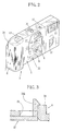
- the transparent supplement cover 32 is selected, as shown in Fig.2, the logotype 17 becomes observable.
- the opaque supplement cover 36 is selected, the logotype 17 is covered to be observable only the logotype 37. This opaque supplement cover 36 is manufactured upon receipt of order.
- the outer label 4 is stuck to the lens-fitted photo film unit, to be completed after several examinations. The finished product is wrapped in a gusset package and shipped.
- the transparent supplement cover 32 is also suitable to attach to all the lens-fitted photo film unit in advance.
- the film unit is shipped with the transparent supplement cover 32 attached to the front cover 6.
- the transparent supplement cover 32 is removed from the front cover 6 through the outer label 4, and instead of this , the opaque supplement cover 36 is attached to the front cover 6.
- the logotype 17 is formed at the center front of the unit body 3 in the above embodiment. However, any position is suitable.
- Fig.4 illustrates an embodiment having a logotype on the grip part.
- a front cover 41 that is made from transparent plastic has the grip part on the left side.
- the grip part has a hollow 42, in which a logotype 43 is formed.
- the logotype 43 is formed outside or inside of the front cover 41.
- a transparent supplement cover 48 is selected, whereas in case of another logotype 52, an opaque supplement cover 51 is selected.
- These supplement covers 48 and 51 are fitted in the hollow 42.
- the transparent supplement cover 48 is a transparent plate, while the opaque supplement cover 51 is a plate having light-shielding property.
- a logotype 52 by grooving or printing is formed on the surface of the opaque supplement cover 51.
- a character's name of an animation, for instance, is used as logotype 52.
- Either the transparent supplement cover 48 or the opaque supplement cover 51 is put on the hollow 42 after applying a transparent adhesive to the surrounding part of the hollow 42. Note that, as shown in Fig.3, the supplement covers 48 and 51 may be engaged with the front cover by a claw. And it is also suitable to use an opaque adhesive or a double-coated tape in case of using the opaque supplement cover 51.
- a logotype 57 is formed on the surface of a front cover 56.
- the outer label 4 is selected, whereas in case the logotype 57 is not used, an outer label 59 is selected.
- the outer label 4 or 59 is stuck on the center of the unit body 58.
- the outer label 59 not only covers the logotype 57, but also another logotype 62 is printed thereon.
- a taking opening 60 and a finder opening 61 are respectively formed in parts corresponding to the protruding section 9 and the finder objective window 10 of the unit body 58.
- the outer label is a sheet to be attached to a part of the unit body.
- the outer label of the present specification includes a box for containing the unit body.
- the front cover needs not the hollow.
- the transparent supplement plate 48 is not needed in case the hollow 42 is omitted.
- the opaque supplement cover 36 may be omitted to cover the logotype 43 with the outer label.
Landscapes
- Physics & Mathematics (AREA)
- General Physics & Mathematics (AREA)
- Engineering & Computer Science (AREA)
- Microelectronics & Electronic Packaging (AREA)
- Structure And Mechanism Of Cameras (AREA)
- Purses, Travelling Bags, Baskets, Or Suitcases (AREA)
- Camera Bodies And Camera Details Or Accessories (AREA)
Abstract
Description
- The present invention relates a lens-fitted photo film unit and its manufacturing method, more particularly to the lens-fitted photo film unit that a letter or a mark formed on the unit body is selectively observable.
- A lens-fitted photo film unit with a simple taking mechanism has been produced so that they can enjoy taking pictures easily and anytime. The lens-fitted photo film unit is widely used due to its convenience that photography is immediately possible after purchase, and just asking a photo-lab for photofinishing is needed.
- The lens-fitted photo film unit consists of a unit body with an unexposed photographic film preloaded, and an outer label surrounding at least a part of the unit body like a belt. The unit body consists of a main body with a simple taking mechanism attached, a front cover and a rear cover covering around the main body.
- Recently, an illegal sale that a new photographic film is loaded in an empty lens-fitted photo film unit after removing an exposed photographic film has been done. So as to cope with such illegal film reloading, a name of a manufacturer, a letter of a brand, a mark or a trademark of a company indicating its origin is formed on the front cover or the rear cover. The letter and the mark are formed by making grooves or irregularities around its contour upon plastic molding.
- The lens-fitted photo film unit is used as a gift for helping sales promotion or a present to customers. In such a case, it is preferable to add the name or the mark of the gift-providing company to the unit body on behalf of the manufacturer. It is necessary for this purpose to prepare an injection mold in which the letter of the company are formed. In case of small production, however, manufacturing cost is remarkably raised as molding is expensive. Accordingly it is used a replaceable core or telescopic on which the name of the gift-providing company is engraved, so as to be fitted into a hollow part of the molding (See Japanese Patent laid-open Publication No.10-260509). In case the telescopic is used, however, as the injection mold has a water pipe for rapid resin cooling, the mold is deteriorated and the resin cooling takes time. As a result manufacturing cost is raised.
- An object of the present invention is to provide a lens-fitted photo film unit of which a letter or a mark is changeable easily and cheaply.
- In order to achieve the above object, the lens-fitted photo film unit of the present invention is provided with a supplement cover, which is attached to the outside of the lens-fitted photo film unit, for covering the letter or the mark to be visible from outside. The letter or the mark is indicated by making irregularities or printing. When the letter or the mark is done on an opaque part of the lens-fitted photo film unit, the letter or the mark is formed on an outside of the opaque part. Meanwhile, when done on a transparent part, the letter or the mark is formed on an outside or an inside of the transparent part. In case an outline of the letter or the mark is represented by groove or protrusion, protrusion or groove is formed on the mold. The groove or protrusion of the letter or the mark on the product is formed in simultaneous with mold forming.
- There are a transparent type and an opaque type in the supplement cover. When the letter or the mark originally formed on the lens-fitted photo film unit is used, the transparent type is selected. When another letter or mark is used, the opaque type is selected.
- According to the preferred embodiment of the present invention, either a first outer label or a second outer label is selected, and either of them is attached to the unit body. The first outer label has an opening which exposes the letter or the mark of the lens-fitted photo film unit so as to be visible. The second outer label covers the letter or the mark so as to be invisible. There forms another letter or mark on this second outer label.
- According to the present invention, the letter or the mark of the lens-fitted photo film unit is made visible or invisible by selecting either the transparent type or the opaque type in the supplement cover, or by selecting either the outer label with opening or the outer label without opening. The letter or the mark can be easily and cheaply changed by use of the supplement cover or the outer label having different letter or mark thereon. Moreover, it is convenient in that the unit body can be commonly made use of.
- The above and other objects and advantages of the present invention will become apparent from the following detailed description of the preferred embodiments when read in association with the accompanying drawings, which are given by way of illustration only and thus are not limiting the present invention. In the drawings, like reference numerals designate like or corresponding parts throughout the several views, and wherein:
- Figure 1 is an exploded perspective view of a lens-fitted photo film unit of the present invention;
- Figure 2 is a front perspective view of the lens-fitted photo film unit with a transparent supplement cover attached;
- Figure 3 is an essential cross section showing a state in which the transparent supplement cover is attached;
- Figure 4 is an exploded perspective view of the lens-fitted photo film unit illustrating another embodiment of supplement covers; and
- Figure 5 is an exploded perspective view illustrating an embodiment selecting an outer label.
-
- In Fig.1, a lens-fitted photo film unit consists of a
unit body 3 and an outer label 4. Theunit body 3 is constituted of a main body (not shown), a front cover 6, and arear cover 7. An unexposed photographic film is incorporated in a base of the main body made from opaque plastic and a simple taking mechanism is attached to the base. The front cover 6 and therear cover 7, made from opaque plastic, are attached to the front or the behind of the main body (See USP5.918.082 issued on 29 June, 1999). - The front of the
unit body 3 is provided with a takinglens 8, a finder objective window 10, aflash projector 11, and aflash switch 12. Arelease button 13, afilm counter window 14, and a flashcompletion indicator lamp 15 are provided on the top of theunit body 3. A take-up wheel 16 and a finder eyepiece window (not shown) are provided on the rear of theunit body 3. - A
logotype 17 for indicating the source is formed observable on the upper part of the takinglens 8. Thelogotype 17 such as a letter(including a number) or a mark is formed outside the front cover 6. Thelogotype 17 is a name or a mark of a manufacturer and a brand. The letter or the mark is represented by groove or convex line along a contour thereof. The groove or the convex is made by molding in synchronization with plastic molding. Additionally, thelogotype 17 may be formed by printing. A hollow 31 is formed on the front of the front cover 6. The takinglens 8, the finder objective window 10, and thelogotype 17 are positioned within the hollow 31. Agroove section 33 is formed in the hollow 31. Anumeral 30 is an opening for assembling and adjusting. - Either a
transparent supplement cover 32 or anopaque supplement cover 36 is attached to the hollow 31. Thetransparent supplement cover 32 is selected when indicating thelogotype 17 formed on the front cover in advance. Theopaque supplement cover 36 is selected when indicating an anotherlogotype 37 in place of thelogotype 17. Note that thetransparent supplement cover 32 may be semitransparent or colored in addition to completely transparent because it is for making thelogotype 17 observable. - The
transparent supplement cover 32 consists of a thintransparent plate 32a and aclaw 32b projecting from the rear of thetransparent plate 32a. Thetransparent plate 32a, having an approximate same size as the hollow 31 of the front cover 6, is fitted in the hollow 31 of the front cover 6, so that the front of the front cover 6 and the front of thetransparent supplement cover 32 turns to be a successive surface. Alens opening 32c and afinder opening 32d are formed on thetransparent plate 32a, so as to expose the takinglens 8 and the finder objective window 10 respectively. Moreover, a protruding section 9 is formed on thetransparent plate 32a so as to surround thelens opening 32c. - As shown in Fig.3, a
protrusion 34 for engaging with theclaw 32b is formed on the side of thegroove section 33. By bending theclaw 32b inward, thetransparent supplement cover 32 is removably fitted to the front cover 6. - The
opaque supplement cover 36 has the same shape with thetransparent supplement cover 32 and alogotype 37 is formed thereon. Thislogotype 37 is indicated by a contour, which is grooved, made protrusion, or printed. When theopaque supplement cover 36 is selected, thelogotype 17 is covered, to be observable anotherlogotype 37. Note that another logotype is not formed on theopaque supplement cover 36 in case thelogotype 17 has only to be invisibly covered. - The outer label 4 is stuck detachable to the
unit body 3 by use of an adhesive so as to cover the center of theunit body 3 like a belt. This outer label 4 is made of a thin plastic or a paper, on which a letter, a design, directions for use, and so forth are printed. The outer label 4 has afront opening 21 which has approximately the same size as the supplement covers 32 and 36. In case of covering the contours of the supplement covers 32 and 36, thefront opening 21 is made smaller than the supplement covers 32 and 36. The protruding section 9, the finder objective window 10, and thelogotype 17 are positioned within thefront opening 21. Acounter opening 22, aflash lamp opening 23, and afinder opening 24 are respectively formed in parts corresponding to thefilm counter window 14, the flashcompletion indicator lamp 15, and the finder eyepiece window. And theopening 30 is covered by the outer label 4. - Then, assembling method is explained. The taking mechanism, the taking
lens 8 and so forth is attached to the main body. Then the front cover 6 is attached thereto. After an unexposed photographic film is loaded into the main body in a darkroom, therear cover 7 is attached. Either thesupplement cover logotype 17 or not, is fitted in a hollow 31. When thetransparent supplement cover 32 is selected, as shown in Fig.2, thelogotype 17 becomes observable. When theopaque supplement cover 36 is selected, thelogotype 17 is covered to be observable only thelogotype 37. Thisopaque supplement cover 36 is manufactured upon receipt of order. The outer label 4 is stuck to the lens-fitted photo film unit, to be completed after several examinations. The finished product is wrapped in a gusset package and shipped. - It is also suitable to attach the
transparent supplement cover 32 to all the lens-fitted photo film unit in advance. In case the logotype is kept unchanged, the film unit is shipped with thetransparent supplement cover 32 attached to the front cover 6. In case the logotype is changed, on the other hand, thetransparent supplement cover 32 is removed from the front cover 6 through the outer label 4, and instead of this , theopaque supplement cover 36 is attached to the front cover 6. - The
logotype 17 is formed at the center front of theunit body 3 in the above embodiment. However, any position is suitable. Fig.4 illustrates an embodiment having a logotype on the grip part. A front cover 41 that is made from transparent plastic has the grip part on the left side. The grip part has a hollow 42, in which a logotype 43 is formed. The logotype 43 is formed outside or inside of the front cover 41. - In case of using the logotype 43, a
transparent supplement cover 48 is selected, whereas in case of anotherlogotype 52, an opaque supplement cover 51 is selected. These supplement covers 48 and 51 are fitted in the hollow 42. Thetransparent supplement cover 48 is a transparent plate, while the opaque supplement cover 51 is a plate having light-shielding property. Alogotype 52 by grooving or printing is formed on the surface of the opaque supplement cover 51. A character's name of an animation, for instance, is used aslogotype 52. Either thetransparent supplement cover 48 or the opaque supplement cover 51 is put on the hollow 42 after applying a transparent adhesive to the surrounding part of the hollow 42. Note that, as shown in Fig.3, the supplement covers 48 and 51 may be engaged with the front cover by a claw. And it is also suitable to use an opaque adhesive or a double-coated tape in case of using the opaque supplement cover 51. - In Fig.5, a
logotype 57 is formed on the surface of afront cover 56. In case thelogotype 57 is used, the outer label 4 is selected, whereas in case thelogotype 57 is not used, anouter label 59 is selected. Theouter label 4 or 59 is stuck on the center of theunit body 58. - The
outer label 59 not only covers thelogotype 57, but also anotherlogotype 62 is printed thereon. A takingopening 60 and afinder opening 61 are respectively formed in parts corresponding to the protruding section 9 and the finder objective window 10 of theunit body 58. - In the above embodiment, the outer label is a sheet to be attached to a part of the unit body. However, the outer label of the present specification includes a box for containing the unit body. In case the supplement cover may be protruded, the front cover needs not the hollow. In the embodiment shown in Fig. 4, the
transparent supplement plate 48 is not needed in case the hollow 42 is omitted. Furthermore, theopaque supplement cover 36 may be omitted to cover the logotype 43 with the outer label. - Although the present invention has been fully described by the way of the preferred embodiments thereof with reference to the accompanying drawings, various changes and modifications will be apparent to those having skill in this field. Therefore, unless otherwise these changes and modifications depart from the scope of the present invention, they should be construed as included therein.
Claims (14)
- A lens-fitted photo film unit with an unexposed photographic film preloaded comprising:a letter or a mark (17,43) formed in said lens-fitted photo film unit, said letter or said mark (17,43) being observable from outside; anda supplement cover (32,36,48,51) attached to an outer surface of said lens-fitted photo film unit so as to cover said letter or said mark (17,43).
- A lens-fitted photo film unit as claimed in claim 1 further comprising a hollow part (31,42) formed in said outer surface of said lens-fitted photo film unit, said letter or said mark (17,43) formed in said hollow part (31,42), and said supplement cover (32,36,48,51) being fitted to said hollow part (31).
- A lens-fitted photo film unit as claimed in claim 2, wherein said lens-fitted photo film unit has a unit body (3,45) with a front cover (6,41) and a rear cover (7) attached.
- A lens-fitted photo film unit as claimed in claim 3, wherein said hollow part (31) is formed on said front cover (6,41).
- A lens-fitted photo film unit as claimed in claim 4, wherein said supplement cover (32,48) is transparent, so as to make said letter or said mark (17,43) visible through said supplement cover(32,48).
- A lens-fitted photo film unit as claimed in claim 4, wherein said supplement cover (36,51) is opaque, so as to make said letter or said mark (17,43) invisible.
- A lens-fitted photo film unit as claimed in claim 6, wherein said opaque supplement cover (36,51) has another letter or mark (37,52) formed on an outer surface thereof.
- A lens-fitted photo film unit comprising:a unit body (58) with an unexposed photographic film preloaded;a letter or a mark (57) formed on said unit body(3), said letter or said mark (57) being observable from outside; andan outer label (4,59) attached outside of said unit body (58) so as to cover said letter or said mark (57).
- A lens-fitted photo film unit as claimed in claim 8, wherein said outer label (59) is printed another letter or mark (62).
- A manufacturing method of a lens-fitted photo film unit, said lens-fitted photo film unit having a unit body (3) with an unexposed photographic film preloaded, said method comprising the steps of:forming a letter or a mark (17,43) on said unit body (3,45) so as to be observable from outside; andattaching either a transparent supplement cover (32,48) or an opaque supplement cover (36,51) to said unit body (3,45), said letter or said mark (17,43) being visible through said transparent supplement cover (32,48), and said letter or said mark (17,43) being invisible through said opaque supplement cover (36,51).
- A method as claimed in claim 10, wherein said opaque supplement cover (36,51) has another letter or mark (37) formed outside thereof.
- A method as claimed in claim 11, wherein said letter or mark (17,43) is formed in a hollow part (31,42) of said unit body (3,45), and said transparent supplement cover (32,48) or said opaque supplement cover (36,51) is fitted in said hollow part (31,42).
- A manufacturing method of a lens-fitted photo film unit, said lens-fitted photo film unit having a unit body (58) with an unexposed photographic film preloaded, said method comprising the steps of:forming a letter or a mark (57) on said unit body (58) so as to be observable from outside; andattaching either a first outer label (4) or a second outer label (59) to said unit body (58), said first outer label (4) having an opening (21) that exposes said letter or said mark (57) so as to be visible, said second outer label (59) covers said letter or said mark (57) so as to be invisible.
- A method as claimed in claim 12, wherein said second outer label (59) has another letter or mark (62) formed on an outer surface thereof.
Applications Claiming Priority (2)
| Application Number | Priority Date | Filing Date | Title |
|---|---|---|---|
| JP2001178148A JP2002365773A (en) | 2001-06-13 | 2001-06-13 | Lens-fitted photographic film unit |
| JP2001178148 | 2001-06-13 |
Publications (2)
| Publication Number | Publication Date |
|---|---|
| EP1267202A1 true EP1267202A1 (en) | 2002-12-18 |
| EP1267202B1 EP1267202B1 (en) | 2007-09-05 |
Family
ID=19018895
Family Applications (1)
| Application Number | Title | Priority Date | Filing Date |
|---|---|---|---|
| EP02254059A Expired - Lifetime EP1267202B1 (en) | 2001-06-13 | 2002-06-11 | Manufacturing method for a lens-fitted photo film unit having a selectively observable mark |
Country Status (7)
| Country | Link |
|---|---|
| US (1) | US6603926B2 (en) |
| EP (1) | EP1267202B1 (en) |
| JP (1) | JP2002365773A (en) |
| KR (1) | KR100461226B1 (en) |
| CN (1) | CN1230710C (en) |
| DE (1) | DE60222208T2 (en) |
| TW (1) | TW588212B (en) |
Families Citing this family (3)
| Publication number | Priority date | Publication date | Assignee | Title |
|---|---|---|---|---|
| US6714727B1 (en) | 2003-04-14 | 2004-03-30 | Eastman Kodak Company | Camera capable of having alternatively positioned mode indicator |
| KR100595225B1 (en) * | 2004-01-28 | 2006-07-03 | 엘지전자 주식회사 | Camera housing of mobile communication terminal |
| JP2017021601A (en) * | 2015-07-10 | 2017-01-26 | 株式会社ユピテル | Device and program |
Citations (5)
| Publication number | Priority date | Publication date | Assignee | Title |
|---|---|---|---|---|
| US3911459A (en) * | 1972-03-02 | 1975-10-07 | Rollei Werke Franke Heidecke | Automatic and manual setting means for photographic diaphragms |
| US4204756A (en) * | 1975-07-25 | 1980-05-27 | Minolta Camera Kabushiki Kaisha | Camera exposure factor indicating device |
| US5369230A (en) * | 1991-09-13 | 1994-11-29 | Asahi Kogaku Kogyo Kabushiki Kaisha | Switch apparatus |
| US5606388A (en) * | 1993-11-05 | 1997-02-25 | Fuji Photo Film Co., Ltd. | Photo film cassette for lens-fitted photo film unit and cassette marking method |
| EP0778492A1 (en) * | 1995-12-08 | 1997-06-11 | Eastman Kodak Company | Photographic cameras |
Family Cites Families (10)
| Publication number | Priority date | Publication date | Assignee | Title |
|---|---|---|---|---|
| JP3088022B2 (en) * | 1991-03-11 | 2000-09-18 | 富士写真フイルム株式会社 | Film unit with lens and method of manufacturing the same |
| US5600391A (en) * | 1992-09-15 | 1997-02-04 | Eastman Kodak Company | One piece viewfinder and fabrication process |
| KR950033639A (en) * | 1994-05-10 | 1995-12-26 | 이동섭 | Disposable camera to print your logo |
| US5832312A (en) * | 1996-02-22 | 1998-11-03 | Eastman Kodak Company | Watertight body for accommodating a photographic camera |
| JP3670408B2 (en) | 1996-08-28 | 2005-07-13 | 富士写真フイルム株式会社 | Sprocket and film hoisting device |
| US5711424A (en) * | 1996-08-29 | 1998-01-27 | Eastman Kodak Company | Packaged one-time-use camera and accessory belt clip |
| JPH10260509A (en) | 1997-03-17 | 1998-09-29 | Fuji Photo Film Co Ltd | Production of component for film unit with lens |
| JPH11237676A (en) * | 1998-02-23 | 1999-08-31 | Kanji Nakano | Disposable camera capable of imprinting character, logo and name |
| JP2000221642A (en) * | 1999-01-29 | 2000-08-11 | Konica Corp | Film unit with lens |
| JP3123544B2 (en) * | 1999-05-07 | 2001-01-15 | 敏機 山田 | Still camera with luminous body |
-
2001
- 2001-06-13 JP JP2001178148A patent/JP2002365773A/en active Pending
-
2002
- 2002-04-19 KR KR10-2002-0021597A patent/KR100461226B1/en not_active Expired - Fee Related
- 2002-04-26 TW TW091108673A patent/TW588212B/en not_active IP Right Cessation
- 2002-06-11 EP EP02254059A patent/EP1267202B1/en not_active Expired - Lifetime
- 2002-06-11 DE DE60222208T patent/DE60222208T2/en not_active Expired - Fee Related
- 2002-06-12 US US10/166,679 patent/US6603926B2/en not_active Expired - Fee Related
- 2002-06-13 CN CNB021232245A patent/CN1230710C/en not_active Expired - Fee Related
Patent Citations (5)
| Publication number | Priority date | Publication date | Assignee | Title |
|---|---|---|---|---|
| US3911459A (en) * | 1972-03-02 | 1975-10-07 | Rollei Werke Franke Heidecke | Automatic and manual setting means for photographic diaphragms |
| US4204756A (en) * | 1975-07-25 | 1980-05-27 | Minolta Camera Kabushiki Kaisha | Camera exposure factor indicating device |
| US5369230A (en) * | 1991-09-13 | 1994-11-29 | Asahi Kogaku Kogyo Kabushiki Kaisha | Switch apparatus |
| US5606388A (en) * | 1993-11-05 | 1997-02-25 | Fuji Photo Film Co., Ltd. | Photo film cassette for lens-fitted photo film unit and cassette marking method |
| EP0778492A1 (en) * | 1995-12-08 | 1997-06-11 | Eastman Kodak Company | Photographic cameras |
Also Published As
| Publication number | Publication date |
|---|---|
| EP1267202B1 (en) | 2007-09-05 |
| DE60222208T2 (en) | 2008-01-10 |
| CN1230710C (en) | 2005-12-07 |
| TW588212B (en) | 2004-05-21 |
| KR100461226B1 (en) | 2004-12-13 |
| DE60222208D1 (en) | 2007-10-18 |
| US6603926B2 (en) | 2003-08-05 |
| KR20020095055A (en) | 2002-12-20 |
| JP2002365773A (en) | 2002-12-18 |
| US20020191972A1 (en) | 2002-12-19 |
| CN1391136A (en) | 2003-01-15 |
Similar Documents
| Publication | Publication Date | Title |
|---|---|---|
| JPH04282635A (en) | Film unit with lens and its production | |
| US6603926B2 (en) | Lens-fitted photo film unit and manufacturing method therefor | |
| JP3036718B2 (en) | Film unit with lens | |
| US5864717A (en) | Photographic roll-film pack with a picture-taking lens | |
| US4139294A (en) | Camera with pin registration for film and end-of-film indication means | |
| JPH06202221A (en) | Specific-character insertion device of camera | |
| US6768866B2 (en) | Lens-fitted photo film unit and method of producing the same | |
| US6625400B2 (en) | Brownie film and camera | |
| US5381198A (en) | Adaptor for instant camera | |
| US5978608A (en) | Lens-fitted film unit having a shutter mechanism adapted for data recording | |
| JPH10288827A (en) | Film unit with lens, production of case member for it and identification method of it | |
| TW594374B (en) | A film device with lenses | |
| JP3509975B2 (en) | Film unit with lens | |
| JP2001337421A (en) | Film unit with lens | |
| JPH11327093A (en) | Disposable camera having outside cover to be split | |
| JPH075558A (en) | Single-use camera with indicator lamp | |
| JP2002023317A (en) | Film unit with lens | |
| JPH068588Y2 (en) | Film unit with lens | |
| JP2001215664A (en) | Film unit with lens | |
| JPH1048783A (en) | Photographic film cartridge | |
| JP2002372770A (en) | Film counter display device | |
| EP1128205A1 (en) | Lens-fitted photo film unit having auxiliary module | |
| JP2004119852A (en) | Electronics | |
| JP2000302183A (en) | Film unit package with lens and packaging method therefor | |
| JP2002341494A (en) | Lens-fitted photographic film unit |
Legal Events
| Date | Code | Title | Description |
|---|---|---|---|
| PUAI | Public reference made under article 153(3) epc to a published international application that has entered the european phase |
Free format text: ORIGINAL CODE: 0009012 |
|
| AK | Designated contracting states |
Kind code of ref document: A1 Designated state(s): AT BE CH CY DE DK ES FI FR GB GR IE IT LI LU MC NL PT SE TR |
|
| AX | Request for extension of the european patent |
Free format text: AL;LT;LV;MK;RO;SI |
|
| 17P | Request for examination filed |
Effective date: 20030617 |
|
| AKX | Designation fees paid |
Designated state(s): DE FR GB |
|
| 17Q | First examination report despatched |
Effective date: 20040804 |
|
| GRAP | Despatch of communication of intention to grant a patent |
Free format text: ORIGINAL CODE: EPIDOSNIGR1 |
|
| RTI1 | Title (correction) |
Free format text: MANUFACTURING METHOD FOR A LENS-FITTED PHOTO FILM UNIT HAVING A SELECTIVELY OBSERVABLE MARK |
|
| GRAS | Grant fee paid |
Free format text: ORIGINAL CODE: EPIDOSNIGR3 |
|
| RAP1 | Party data changed (applicant data changed or rights of an application transferred) |
Owner name: FUJIFILM CORPORATION |
|
| GRAA | (expected) grant |
Free format text: ORIGINAL CODE: 0009210 |
|
| AK | Designated contracting states |
Kind code of ref document: B1 Designated state(s): DE FR GB |
|
| REG | Reference to a national code |
Ref country code: GB Ref legal event code: FG4D |
|
| REF | Corresponds to: |
Ref document number: 60222208 Country of ref document: DE Date of ref document: 20071018 Kind code of ref document: P |
|
| ET | Fr: translation filed | ||
| PLBE | No opposition filed within time limit |
Free format text: ORIGINAL CODE: 0009261 |
|
| STAA | Information on the status of an ep patent application or granted ep patent |
Free format text: STATUS: NO OPPOSITION FILED WITHIN TIME LIMIT |
|
| 26N | No opposition filed |
Effective date: 20080606 |
|
| PGFP | Annual fee paid to national office [announced via postgrant information from national office to epo] |
Ref country code: DE Payment date: 20080619 Year of fee payment: 7 |
|
| PGFP | Annual fee paid to national office [announced via postgrant information from national office to epo] |
Ref country code: FR Payment date: 20080617 Year of fee payment: 7 |
|
| PGFP | Annual fee paid to national office [announced via postgrant information from national office to epo] |
Ref country code: GB Payment date: 20080611 Year of fee payment: 7 |
|
| GBPC | Gb: european patent ceased through non-payment of renewal fee |
Effective date: 20090611 |
|
| REG | Reference to a national code |
Ref country code: FR Ref legal event code: ST Effective date: 20100226 |
|
| PG25 | Lapsed in a contracting state [announced via postgrant information from national office to epo] |
Ref country code: FR Free format text: LAPSE BECAUSE OF NON-PAYMENT OF DUE FEES Effective date: 20090630 |
|
| PG25 | Lapsed in a contracting state [announced via postgrant information from national office to epo] |
Ref country code: GB Free format text: LAPSE BECAUSE OF NON-PAYMENT OF DUE FEES Effective date: 20090611 |
|
| PG25 | Lapsed in a contracting state [announced via postgrant information from national office to epo] |
Ref country code: DE Free format text: LAPSE BECAUSE OF NON-PAYMENT OF DUE FEES Effective date: 20100101 |