EP1267150A2 - Seat weight measurement system - Google Patents
Seat weight measurement system Download PDFInfo
- Publication number
- EP1267150A2 EP1267150A2 EP02254008A EP02254008A EP1267150A2 EP 1267150 A2 EP1267150 A2 EP 1267150A2 EP 02254008 A EP02254008 A EP 02254008A EP 02254008 A EP02254008 A EP 02254008A EP 1267150 A2 EP1267150 A2 EP 1267150A2
- Authority
- EP
- European Patent Office
- Prior art keywords
- seat
- weight
- transfer link
- measurement system
- transfer
- Prior art date
- Legal status (The legal status is an assumption and is not a legal conclusion. Google has not performed a legal analysis and makes no representation as to the accuracy of the status listed.)
- Granted
Links
Images


Classifications
-
- G—PHYSICS
- G01—MEASURING; TESTING
- G01G—WEIGHING
- G01G19/00—Weighing apparatus or methods adapted for special purposes not provided for in the preceding groups
- G01G19/40—Weighing apparatus or methods adapted for special purposes not provided for in the preceding groups with provisions for indicating, recording, or computing price or other quantities dependent on the weight
- G01G19/413—Weighing apparatus or methods adapted for special purposes not provided for in the preceding groups with provisions for indicating, recording, or computing price or other quantities dependent on the weight using electromechanical or electronic computing means
- G01G19/414—Weighing apparatus or methods adapted for special purposes not provided for in the preceding groups with provisions for indicating, recording, or computing price or other quantities dependent on the weight using electromechanical or electronic computing means using electronic computing means only
- G01G19/4142—Weighing apparatus or methods adapted for special purposes not provided for in the preceding groups with provisions for indicating, recording, or computing price or other quantities dependent on the weight using electromechanical or electronic computing means using electronic computing means only for controlling activation of safety devices, e.g. airbag systems
-
- B—PERFORMING OPERATIONS; TRANSPORTING
- B60—VEHICLES IN GENERAL
- B60N—SEATS SPECIALLY ADAPTED FOR VEHICLES; VEHICLE PASSENGER ACCOMMODATION NOT OTHERWISE PROVIDED FOR
- B60N2/00—Seats specially adapted for vehicles; Arrangement or mounting of seats in vehicles
- B60N2/02—Seats specially adapted for vehicles; Arrangement or mounting of seats in vehicles the seat or part thereof being movable, e.g. adjustable
- B60N2/04—Seats specially adapted for vehicles; Arrangement or mounting of seats in vehicles the seat or part thereof being movable, e.g. adjustable the whole seat being movable
- B60N2/06—Seats specially adapted for vehicles; Arrangement or mounting of seats in vehicles the seat or part thereof being movable, e.g. adjustable the whole seat being movable slidable
- B60N2/07—Slide construction
- B60N2/0702—Slide construction characterised by its cross-section
- B60N2/0705—Slide construction characterised by its cross-section omega-shaped
-
- B—PERFORMING OPERATIONS; TRANSPORTING
- B60—VEHICLES IN GENERAL
- B60N—SEATS SPECIALLY ADAPTED FOR VEHICLES; VEHICLE PASSENGER ACCOMMODATION NOT OTHERWISE PROVIDED FOR
- B60N2/00—Seats specially adapted for vehicles; Arrangement or mounting of seats in vehicles
- B60N2/02—Seats specially adapted for vehicles; Arrangement or mounting of seats in vehicles the seat or part thereof being movable, e.g. adjustable
- B60N2/04—Seats specially adapted for vehicles; Arrangement or mounting of seats in vehicles the seat or part thereof being movable, e.g. adjustable the whole seat being movable
- B60N2/06—Seats specially adapted for vehicles; Arrangement or mounting of seats in vehicles the seat or part thereof being movable, e.g. adjustable the whole seat being movable slidable
- B60N2/07—Slide construction
- B60N2/0702—Slide construction characterised by its cross-section
- B60N2/0715—C or U-shaped
-
- B—PERFORMING OPERATIONS; TRANSPORTING
- B60—VEHICLES IN GENERAL
- B60N—SEATS SPECIALLY ADAPTED FOR VEHICLES; VEHICLE PASSENGER ACCOMMODATION NOT OTHERWISE PROVIDED FOR
- B60N2/00—Seats specially adapted for vehicles; Arrangement or mounting of seats in vehicles
- B60N2/02—Seats specially adapted for vehicles; Arrangement or mounting of seats in vehicles the seat or part thereof being movable, e.g. adjustable
- B60N2/04—Seats specially adapted for vehicles; Arrangement or mounting of seats in vehicles the seat or part thereof being movable, e.g. adjustable the whole seat being movable
- B60N2/06—Seats specially adapted for vehicles; Arrangement or mounting of seats in vehicles the seat or part thereof being movable, e.g. adjustable the whole seat being movable slidable
- B60N2/07—Slide construction
- B60N2/0722—Constructive details
- B60N2/0732—Attachment of seat frame to the slide, e.g. eyelets
Definitions
- the present invention relates to a system for accurately detecting the weight of a person seated in a vehicle seat.
- Automobiles are equipped with restraint systems, such as seat belts, and inflatable restraint systems, such as airbags, to secure safety for passengers.
- these safety devices could actually injure the occupants.
- an occupant of the front passenger seat may be injured by the deployment of an airbag if the occupant is a baby or child.
- the amount of gas introduced into the airbag, an airbag inflating speed, or a pre-tension of the seat belt are adjusted according to the weight of a passenger.
- One known device provides a gel-filled cushion integrally attached to the vehicle seat, as described in U.S. Patent No. 6,041,658.
- the pressure on the liquid in the cushion is measured to determine the occupant's weight.
- the disadvantage of this known device is that the accuracy of the weight measurement varies with the position of the occupant and the angle of the vehicle seat back.
- the puncture-resistance feature of the gel-filled bag is not perfect.
- the gel-filled bags often have a sealing problem or get punctured, resulting in gel leakage from the bag. If the leakage is undetected, the weight measurement result will be inaccurate. Accordingly, it is desirable to provide a reliable weight measurement system that provides an accurate measurement regardless of the seated position of the occupant or the position of the vehicle seat back.
- Another known measurement system includes the use of force sensors at a plurality of support points on the seat. Typically, four load cells are used, each located at one of the four corners of the seat, between the seat and the vehicle floor.
- the disadvantage of this system is that each sensor significantly increases the cost of the weight detection system.
- the weight measured by each sensor could vary, resulting in a wide range of force difference between the sensors.
- electronics are used to average the signals received by the sensors to determine an average weight sensed by the four sensors.
- the averaging process introduces further errors in the measurement.
- the load cells themselves can be damages by crash forces or other overloads.
- an accurate weight measurement system that is also cost-efficient, easy to install and repair. It is further desirable to provide a system that provides failure detection capability that alerts the user of a failure and thus reduces the risk of incorrect information provided to a safety restraint system. In the event that the vehicle floor or seat becomes distorted, a wracking load may be placed on the load sensors, and the unequal loading may result in inaccurate weight measurement. Accordingly, it is desirably to provide a system that can transfer wracking loads effectively to avoid inaccurate measurement of the passenger's weight. Finally, a weight measurement system that protects the sensor itself from overloads is highly desirable.
- a weight measurement system for measuring the weight of an occupant in a vehicle seat.
- a sensor is positioned at the close to the fore-and-aft center of gravity of an occupant of a vehicle seat and a load transfer link is used to transfer the weight from the front portion of the vehicle seat to the sensor to be measured.
- the transfer link is a selectively compliant beam having a first rigid section and a second rigid section connected to each other via a flexible area.
- the first and second rigid sections preferably include wing portions for increasing the rigidity of the sections.
- the flexible area is more compliant than the rigid sections. In one embodiment of the invention, the flexible area has a jog to increase the flex.
- the load transfer link is configured to transition a load placed on the front portion of the link to the rear portion.
- the load transfer link is made of a high strength, low alloy steel.
- the load transfer link is connected to the vehicle seat and the rail assembly using bushings and fasteners.
- the front portion of the transfer link is connected to the front portion of the vehicle seat using a bolt and an elastic or plastic bushing.
- the rear portion of the transfer link is connected to the rear portion of the vehicle seat using a bolt and an elastic or plastic bushing. The bushing is compliant, thus allowing the transfer link to move in an angular direction but restricting the translational movement.
- the transfer link is preferably attached to the mounting bar of the rail assembly by bushings and fasteners.
- the transfer link is attached to the top of the mounting bar, such that the transfer link is seated between the vehicle seat and the mounting bar.
- the transfer link is attached below the mounting bar, such that it is seated between the fixed rail and the mounting bar. In this embodiment, the transfer link is positioned to allow the link to sustain maximum crash forces, thus reducing the risk of failure and the cost of repair.
- Figure 1 is a cross-section of the seat weight measurement system 10 and shows the components of the system on one side of the vehicle seat. The identical components are provided on the other side of the vehicle seat. For the purposes of simplicity, only the components of one side are shown.
- Figure 2 shows the exploded view of the seat weight measurement system on one side of the vehicle seat.
- the seat weight measurement system 10 measures the weight of a vehicle occupant seated in a vehicle seat 12.
- the vehicle seat 12 includes a front portion 14 and a rear portion 16.
- the front portion 14 and rear portion 16 are used herein to refer generally to the front and back regions, respectively, and should not be interpreted to be limited to the front edge and the back edge of the seat.
- the seat 12 is mounted on the vehicle floor (not shown) by a rail assembly 20, including a fixed rail member 22 and a mounting bar 24.
- the fixed rail member 22 is attached to the floor of the vehicle and the mounting bar 24 slidably engages the fixed rail member 22 to move the seat 12 forward and backward.
- the heaviest portion of a vehicle seat is the seat back (not shown) and therefore, the center of gravity of an occupied vehicle seat is toward the back of the seat, near the seat back itself.
- a person seated on a vehicle seat typically leans back against the seat back, resulting in a center of gravity of the person to also be near the back of the seat.
- the weight of the seat and the occupant should be measured at the rear portion 16 of the vehicle seat.
- a pair of sensors 30 are provided at the rear portion of the vehicle seat.
- the sensors used can be of any type known in the art capable of measuring a load placed thereon and providing a signal corresponding to the measured load.
- the force sensor used is a load cell commercially available from Kavlico Corporation in Moorpark, California.
- the sensor is preferably a ceramic capacitive element having a digitally calibrated signal conditioner.
- the sensor should be capable of remaining stable over an extended period of use and should withstand high overload conditions.
- a load transfer link 40 is provided for transferring the weight of the occupant from the front portion 14 of the vehicle seat to the sensors 30 located at the rear portion 16 of the vehicle seat.
- the transfer link 40 is preferably a single, integral structural member that substantially extends across the length of the vehicle seat 12 from the front portion 14 to the rear portion 16.
- the load transfer link 40 is a selectively compliant beam comprised of a spine 41, a first rigid section 42, a flexible area 43 and a second rigid section 44. In the first and second rigid section 42, 44, the transfer link includes wing portions 45 extending from the spine 41 to increase the stiffness of the rigid sections.
- the transfer link 40 is more compliant in the flexible area 43 than in the rigid sections 42, 44 to facilitate the load transfer from the front portion to the rear portion.
- the load transfer link is made of a high strength, low alloy steel.
- the load 50 at the front portion 14 of the vehicle seat 12 results in a primary reaction load 52.
- a primary reaction load 52 At the center of the link 54, there is a transfer of the load to the rear part of the link 56.
- the force at 56 is upward on the link resulting in a downward secondary reaction force at 58 and finally a downward force applied to the seat at 56.
- the length of the link sections 42 and 46 are configured such that the force at the rear portion of the vehicle seat will be equal to the original load 50 placed at the front of the seat. In this configuration, the sensor 30 will be able to measure the load regardless of the position of the weight.
- the weight measurement system of the present invention is integrated at the seat/rail interface.
- the weight measurement system of the present invention remains unaffected by any seat position changes. Moreover, the installation of the seat assembly to the vehicle floor remains unchanged.
- a front bushing 60 is provided at the front portion 14 of the vehicle seat and, in conjunction with a front bolt 62, is used to attach the front portion 14 of the vehicle seat to the front portion 46 of the transfer link 40.
- the front bushing 60 is compliant and allows the transfer link 40 to rotate but does not allow significant translation of the mounting bar 24 relative to the vehicle seat 12.
- a back bushing 64 is provided at the rear portion 16 of the vehicle seat and, in conjunction with a back bolt 66, is used to attach the rear portion 16 of the vehicle seat to the rear portion 48 of the transfer link.
- the bushings are preferably elastic rubber, and more preferably Neoprene, having a durometer of about 70 to 90 Duro. It is within the scope of the present invention to replace the bolts with any known fastener and the bushings with other known pivot means.
- the transfer link 40 is attached to the mounting bar 24 using elastic bushings and bolts.
- a first bushing 70 and first bolt 72 attach the first rigid section 42 of the transfer link 40 to the mounting bar 24.
- a second bushing 74 and second bolt 76 attach the second rigid section 44 of the transfer link 40 to the mounting bar 24. All bushings are preferably elastic, as described above, and more preferably allow maximum angular compliance.
- first and second bolts 72, 76 are vertically fastened into the spine 41 of the transfer link.
- first and second bolts 72, 76 can be positioned horizontally such that the first and second bolts 72, 76 extend horizontally through the wing portions 45 of the first rigid section 42 and second rigid section 44, respectively.
- the load transfer link is positioned between the fixed rail member 22 and the mounting bar 24 of the rail assembly 20.
- the load transfer link 40 is attached to the mounting bar 24 by first and second bushings 70, 74 and first and second bolts 72, 76.
- the difference is that the load transfer link 40, instead of being connected above the mounting bar 24, is connected below the mounting bar 24.
- the load transfer link 40 is further protected from crash forces by being enclosed by the mounting bar 24 and the fixed rail member 22.
- the front portion 46 of the load transfer link 40 extends outside the mounting bar 24 for attachment with the front portion 14 of the vehicle seat 12.
- the rear portion 48 of the load transfer link is in communication with the sensor 30.
- an opening 26 may be provided in the mounting bar 24.
- a sensor 30 can be positioned between the mounting bar 24 and the load transfer link 40.
- the seat weight measurement system 10 includes a load transfer link 40 integrated with seat adjustment components 80, 82.
- This configuration eliminates the need for end bushings by the existing seat adjustment components as pivots.
- the load transfer link 40 measures the weight of an occupied seat through the seat adjustment components 80, 82.
- the seat adjustment component may be a seat adjustment lever or other component that is capable of transferring the weight of a seat and an occupant to the load transfer link 40.
- the first seat adjustment component 80 preferably attaches to a front portion 46 of the transfer link 40.
- the second seat adjustment component 82 preferably attaches to a rear portion 48 of the transfer link 40.
- the first and second seat adjustment components 80, 82 are attached in a manner that enables the load transfer link 40 to rotate in order to transfer the measured weight to the sensor.
- the transfer link 40 is preferably attached to the mounting bar 24 using elastic bushings and bolts. As best shown in Figures 7 and 8, a first bushing 70 and a first bolt 72 attach the first rigid section 42 of the transfer link 40 to the mounting bar 24 and a second bushing 74 and a second bolt 76 attached the second rigid section 44 of the transfer link 40 to the mounting bar 24.
- the load transfer link 40 transfer the weight of the occupant to the sensor for measurement.
- the position of the sensor 30 may vary as long as the sensor receives the load transferred by the link.
- the sensor is located in the seat assembly and moves with the seat.
- the sensor 30 is provided between the mounting rail 24 and the fixed rail member 22. This arrangement provides for the most accurate measurement since the center of gravity of the seat remains stationary with respect to the sensor.
- FIG 10 depicts another embodiment of the load transfer link 40 of the present invention.
- the load transfer link 40 may include a jog 90 for connecting the first rigid section 42 and the second rigid section 44.
- the jog 90 preferably provides increased flex in the load transfer link to facilitate the transfer of weight.
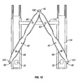
- FIGS 11 and 12 depict another embodiment of the seat weight measurement system of the invention wherein the a three-point mounting technique is used to attach the vehicle seat to the transfer link.
- the seat weight measurement system 100 shown in Figures 11 and 12 utilizes two sensors 30 and two load transfer links 40 to transfer the weight of the occupant to the sensors 30.
- the sensors are preferably positioned between the vehicle seat (not shown) and the mounting bar 24.
- the transfer links 40 are installed in a diagonal V-formation such that the front ends 46 of the transfer links 40 meet at a common connection point 102.
- the vehicle seat is preferably mounted to the transfer links 40 at the common connection point 102, at a first rear connection point 104 and at the second rear connection point 106.
- the front pivots 62 and back pivots 66 operate in the same manner as the pivots disclosed above. To accommodate the three-point mounting, the front pivots 62 are attached to a connecting bar 110.
- the seat is supported at only three locations, making the system impervious to wracking distortions of either the seat or the vehicle floor.
- the common connection point 102 can be positioned either at the front or the rear portion of the vehicle seat. However, because the seat load is typically less at the front of the seat, it is preferred that the common connection point 102 be positioned at the front.
- the seat weight measurement system of the present invention provides accurate measurement of the weight of an occupant in a vehicle seat.
- the system of the present invention minimizes mechanical and electrical complexity and maximizes reliability and accuracy.
- the positioning of the transfer link and the sensors at the interface of the rail assembly and the seat enhances the structural integrity of the system, minimizing the risk of failure and reducing warranty and crash repair costs.
- the transfer link is capable of effectively transferring wracking loads so as to ensure the accuracy of the weight measurement.
- the pivots used in conjunction with the load transfer to facilitate the transfer of weight can be substituted with other fasteners or seat components.
- the relative distances between the pivots of the load transfer link can be adjusted to provide desired characteristics.
- a medium weight person siting on the front edge of the seat might require the air bag deployment to be reduced, while a lighter weight person sitting at the rear of the seat may require stronger deployment.
- the load transfer link can be configured to amplify the weight at the front of the seat to compensate for this effect.
Landscapes
- Engineering & Computer Science (AREA)
- Physics & Mathematics (AREA)
- Theoretical Computer Science (AREA)
- Mechanical Engineering (AREA)
- Transportation (AREA)
- Mathematical Physics (AREA)
- Aviation & Aerospace Engineering (AREA)
- General Physics & Mathematics (AREA)
- Seats For Vehicles (AREA)
- Air Bags (AREA)
- Footwear And Its Accessory, Manufacturing Method And Apparatuses (AREA)
- Geophysics And Detection Of Objects (AREA)
- Automotive Seat Belt Assembly (AREA)
Abstract
Description
Claims (24)
- A weight measure system, comprising:a vehicle seat having a first portion and a second portion;a sensor positioned at the first portion of the seat; anda transfer link extending substantially from the first portion of the seat to the second portion, wherein the transfer link is a beam configured to transfer weight from the second portion of the seat to the first portion.
- A weight measurement system for measuring the weight of an occupant in a vehicle seat, the seat having a first portion and a second portion, the weight measurement system comprising:a pair of sensors positioned at the first portion of the seat;a pair of transfer links extending substantially from the first portion of the seat to the second portion; andwherein the transfer links are selectively compliant beams configured to transfer weight from the second portion of the seat to the first portion.
- A weight measurement system for measuring the weight of an occupant in a vehicle seat, the seat having a first portion and a second portion, the weight measurement system comprising:a sensor positioned at the first portion of the seat;a transfer link extending substantially from the first portion of the seat to the second portion; andwherein the transfer link is a selectively complaint beam configured to transfer weight from the second portion of the seat to the first portion.
- The weight measurement system of claim 3 wherein the transfer link includes a first rigid section, a second rigid section and a flexible area between the first and second rigid sections.
- The weight measurement system of claim 4 wherein the transfer link further includes a spine, a first wing portion extending from the spine at the first rigid section, and a second wing portion extending from the spine at the second rigid section.
- The weight measurement system of claim 3 wherein the transfer link is fastened to the vehicle seat using a bolt.
- The weight measurement system of claim 3 further comprising a compliant bushing positioned between the transfer link and the seat.
- The weight measurement system of claim 3 wherein the transfer link is fastened to the seat at the first portion and the second portion.
- The weight measurement system of claim 5 further comprising a rail assembly having a fixed rail member and a mounting bar slidably engaged with the fixed rail member, and wherein the transfer link is attached to the mounting bar.
- The weight measurement system of claim 9 wherein the transfer link is fastened to a top surface of the mounting bar.
- The weight measurement system of claim 10 wherein the transfer link is positioned between the mounting bar and the fixed rail member.
- A weight measurement system for measuring the weight of an occupant in a vehicle seat, the seat having a first portion and a second portion, the weight measuring system comprising:wherein the transfer link is connected to the vehicle seat via a second bushing and a second fastener.a sensor positioned at the first portion of the seat;a transfer link extending substantially from the first portion of the seat to the second portion, the transfer link having a first rigid section, a second rigid section and a flexible area between the first and second sections, a spine, a first wing portion extending from the spine at the first rigid section, and a second wing portion extending from the spine at the second rigid section;a rail assembly having a fixed rail member and a mounting bar slidably engaged with the fixed rail member, wherein the mounting bar is connected to the transfer link via a first bushing and a first fastener; and
- A method of measuring the weight of an occupant seated in a vehicle seat, the vehicle seat having a first portion and a second portion, the method comprising the steps of:providing sensors in the first portion of the vehicle seat;transferring the occupant's weight from the first portion of the seat to the second portion; andmeasuring the occupant's weight at the first portion of the seat.
- The method of claim 13 wherein the occupant's weight is transferred from the second portion of the seat to the first portion using a transfer link.
- The method of claim 14 wherein the transfer link includes a first rigid section, a second rigid section and a flexible area between the first and second rigid sections, wherein the flexible area is more compliant that the first and second regions.
- The method of claim 15 further providing a rail assembly having a fixed rail member and a mounting bar slidably engaged with the fixed rail member, and wherein the transfer link is connected to the mounting bar.
- The method of measuring the weight of an occupant seated in a vehicle seat, the vehicle seat having a first portion and a second portion, the method comprising the steps of:providing sensors in the first portion of the vehicle seat, and a transfer link extending from the first portion of the vehicle seat to the second portion of the vehicle seat;transferring the occupant's weight from the second portion of the seat to the first portion; andmeasuring the occupant's weight at the first portion of the seat.
- A transfer link comprising:a compliant beam having a first rigid section, a second rigid section and flexible area between the first and second sections; anda first end and a second end, wherein the transfer link is configured to transfer a load placed on the first end to the second end.
- The transfer link of claim 18 further comprising:a spine;a first wing portion extending from the spine at the first rigid section; anda second wing portion extending from the spine at the second rigid section.
- The transfer link of claim 19 further comprising high strength low alloy steel.
- A transfer link comprising:a compliant high strength low alloy steel beam having a first rigid section, a second rigid section and flexible area between the first and second sections;a first end and a second end, wherein the transfer link is configured to transfer a load placed on the first end to the second end;a spine;a first wing portion extending from the spine at the first rigid section; anda second wing portion extending from the spine at the second rigid section.
- A weight measurement system for measuring the weight of an occupant in a vehicle seat having a first portion and a second portion, the seat and the occupant each having a respective center of gravity, the system comprising:a sensor positioned at a sensor location; anda transfer link extending substantially from a second location to the sensor location, wherein the transfer link is a compliant beam configured to transfer weight to the sensor from the second location.
- The weight measurement system of claim 22 wherein the sensor location is substantially under the center of gravity of the seat.
- The weight measurement system of claim 22 wherein the sensor location is substantially under the center of gravity of the occupant.
Applications Claiming Priority (4)
| Application Number | Priority Date | Filing Date | Title |
|---|---|---|---|
| US29823401P | 2001-06-13 | 2001-06-13 | |
| US298234P | 2001-06-13 | ||
| US166235P | 2002-06-03 | ||
| US10/166,235 US6849807B2 (en) | 2001-06-13 | 2002-06-03 | Seat weight measurement system |
Publications (3)
| Publication Number | Publication Date |
|---|---|
| EP1267150A2 true EP1267150A2 (en) | 2002-12-18 |
| EP1267150A3 EP1267150A3 (en) | 2004-01-14 |
| EP1267150B1 EP1267150B1 (en) | 2006-04-26 |
Family
ID=26862093
Family Applications (1)
| Application Number | Title | Priority Date | Filing Date |
|---|---|---|---|
| EP02254008A Expired - Lifetime EP1267150B1 (en) | 2001-06-13 | 2002-06-10 | Seat weight measurement system |
Country Status (5)
| Country | Link |
|---|---|
| US (2) | US6849807B2 (en) |
| EP (1) | EP1267150B1 (en) |
| JP (1) | JP2004345362A (en) |
| AT (1) | ATE324574T1 (en) |
| DE (1) | DE60210866T2 (en) |
Cited By (1)
| Publication number | Priority date | Publication date | Assignee | Title |
|---|---|---|---|---|
| EP1498704A3 (en) * | 2003-07-14 | 2006-10-25 | Delphi Technologies, Inc. | Vehicle occupant weight estimation apparatus |
Families Citing this family (8)
| Publication number | Priority date | Publication date | Assignee | Title |
|---|---|---|---|---|
| US20070135982A1 (en) | 1995-06-07 | 2007-06-14 | Automotive Technologies International, Inc. | Methods for Sensing Weight of an Occupying Item in a Vehicular Seat |
| US7330784B2 (en) * | 1998-11-17 | 2008-02-12 | Automotive Technologies International, Inc. | Weight measuring systems and methods for vehicles |
| US7296649B2 (en) * | 2005-04-12 | 2007-11-20 | Takata Seat Belts, Inc. | Door-mounted seat belt restraint system and method |
| US8365992B2 (en) * | 2006-12-20 | 2013-02-05 | Ncr Corporation | Optical scanner with floating load cell frame |
| CA2770958C (en) * | 2009-08-14 | 2017-11-21 | Robert Bosch Gmbh | System and method for classifying a vehicle occupant |
| JP5781878B2 (en) * | 2011-09-26 | 2015-09-24 | 矢崎総業株式会社 | Signal transmitter / receiver |
| CN103674212B (en) * | 2012-09-19 | 2017-11-28 | 梅特勒-托利多有限公司 | Dynamometer weighing module |
| JP6907262B2 (en) * | 2019-04-22 | 2021-07-21 | 矢崎総業株式会社 | Communication system, vehicle unit, and seat unit |
Family Cites Families (19)
| Publication number | Priority date | Publication date | Assignee | Title |
|---|---|---|---|---|
| US2890852A (en) * | 1955-08-01 | 1959-06-16 | Ralph L Bradley | Car top carrier bracket |
| US3239183A (en) * | 1964-01-28 | 1966-03-08 | Oliver Electrical Mfg Company | Pole mounting bracket |
| US3729159A (en) * | 1971-11-02 | 1973-04-24 | R Foster | Wall forming bracket |
| US3837609A (en) * | 1972-09-18 | 1974-09-24 | White Machine Co | Support bracket for rails and the like |
| US5232243A (en) | 1991-04-09 | 1993-08-03 | Trw Vehicle Safety Systems Inc. | Occupant sensing apparatus |
| US5971432A (en) | 1997-02-15 | 1999-10-26 | Breed Automotive Technology, Inc. | Seat occupant sensing system |
| US6039344A (en) | 1998-01-09 | 2000-03-21 | Trw Inc. | Vehicle occupant weight sensor apparatus |
| US6092838A (en) | 1998-04-06 | 2000-07-25 | Walker; Robert R. | System and method for determining the weight of a person in a seat in a vehicle |
| JP3655745B2 (en) | 1998-04-16 | 2005-06-02 | タカタ株式会社 | Seat weight measuring device |
| US6259167B1 (en) * | 1998-07-09 | 2001-07-10 | Peter Norton | Seat occupant weight sensing system |
| JP4585054B2 (en) * | 1999-03-09 | 2010-11-24 | タカタ株式会社 | Seat weight measuring device |
| US6571647B1 (en) | 1999-03-09 | 2003-06-03 | Takata Corporation | Seat weight measuring apparatus |
| JP2000310239A (en) * | 1999-04-28 | 2000-11-07 | Nsk Ltd | Bearing unit for clutch release |
| US6234437B1 (en) * | 1999-06-09 | 2001-05-22 | Ricardo F. Cabo | Flexible support |
| JP2001108513A (en) * | 1999-09-21 | 2001-04-20 | Takata Corp | Seat load measuring device |
| US6161891A (en) | 1999-10-21 | 2000-12-19 | Cts Corporation | Vehicle seat weight sensor |
| JP2001150997A (en) | 1999-11-04 | 2001-06-05 | Takata Corp | Seat weight measuring device |
| US6231076B1 (en) | 1999-11-16 | 2001-05-15 | Cts Corporation | Automobile seat having seat supporting brackets with a stepped weight sensor |
| US7178870B2 (en) * | 2005-02-14 | 2007-02-20 | Trw Automotive U.S. Llc | Seat load sensing apparatus |
-
2002
- 2002-06-03 US US10/166,235 patent/US6849807B2/en not_active Expired - Lifetime
- 2002-06-10 DE DE60210866T patent/DE60210866T2/en not_active Expired - Fee Related
- 2002-06-10 EP EP02254008A patent/EP1267150B1/en not_active Expired - Lifetime
- 2002-06-10 AT AT02254008T patent/ATE324574T1/en not_active IP Right Cessation
- 2002-06-12 JP JP2002171740A patent/JP2004345362A/en not_active Withdrawn
-
2005
- 2005-02-01 US US11/048,131 patent/US7513475B2/en not_active Expired - Lifetime
Cited By (2)
| Publication number | Priority date | Publication date | Assignee | Title |
|---|---|---|---|---|
| EP1498704A3 (en) * | 2003-07-14 | 2006-10-25 | Delphi Technologies, Inc. | Vehicle occupant weight estimation apparatus |
| US7308347B2 (en) | 2003-07-14 | 2007-12-11 | Delphi Technologies, Inc. | Frame-based occupant weight estimation apparatus having compliant load transfer mechanism |
Also Published As
| Publication number | Publication date |
|---|---|
| JP2004345362A (en) | 2004-12-09 |
| US20050151046A1 (en) | 2005-07-14 |
| DE60210866D1 (en) | 2006-06-01 |
| US7513475B2 (en) | 2009-04-07 |
| DE60210866T2 (en) | 2006-12-07 |
| EP1267150B1 (en) | 2006-04-26 |
| US20030071491A1 (en) | 2003-04-17 |
| US6849807B2 (en) | 2005-02-01 |
| ATE324574T1 (en) | 2006-05-15 |
| EP1267150A3 (en) | 2004-01-14 |
Similar Documents
| Publication | Publication Date | Title |
|---|---|---|
| US6323444B1 (en) | Seat weight measuring apparatus | |
| JP3793756B2 (en) | Weight classification system | |
| US7143658B2 (en) | Deflection plate weight sensor for vehicle seat | |
| KR20050014023A (en) | Seat Belt Tension Sensor | |
| JP3730959B2 (en) | Sensor assembly for measuring the weight of a vehicle seat | |
| US6849807B2 (en) | Seat weight measurement system | |
| US6786104B1 (en) | Seat weight measuring apparatus | |
| US6670560B2 (en) | Sensor integrated bracket for weight classification | |
| US6759603B2 (en) | Weight sensor assembly with overload spring | |
| EP1491387B1 (en) | Frame-based bladder apparatus for seat occupant weight estimation | |
| JP2002537174A (en) | Method and apparatus for sensing occupant weight | |
| CN1362922A (en) | Weight sensor assembly for determining seat occupant weight | |
| US6499360B1 (en) | Torsional sensing load cell with overload protection | |
| HK1053167A1 (en) | Seat weight measurement system | |
| US7091426B2 (en) | Occupant weight detection system having linked weight detection means with maintained positional relationships | |
| JP3812905B2 (en) | Occupant detection device | |
| JP2003194621A (en) | Load detection structure for vehicle seats | |
| EP1498704B1 (en) | Vehicle occupant weight estimation apparatus | |
| US20020105178A1 (en) | Combination sensor systems for occupant sensing |
Legal Events
| Date | Code | Title | Description |
|---|---|---|---|
| PUAI | Public reference made under article 153(3) epc to a published international application that has entered the european phase |
Free format text: ORIGINAL CODE: 0009012 |
|
| AK | Designated contracting states |
Kind code of ref document: A2 Designated state(s): AT BE CH CY DE DK ES FI FR GB GR IE IT LI LU MC NL PT SE TR |
|
| AX | Request for extension of the european patent |
Free format text: AL;LT;LV;MK;RO;SI |
|
| RIC1 | Information provided on ipc code assigned before grant |
Ipc: 7B 60R 21/01 B Ipc: 7B 60N 2/07 B Ipc: 7G 01G 19/414 A |
|
| PUAL | Search report despatched |
Free format text: ORIGINAL CODE: 0009013 |
|
| AK | Designated contracting states |
Kind code of ref document: A3 Designated state(s): AT BE CH CY DE DK ES FI FR GB GR IE IT LI LU MC NL PT SE TR |
|
| AX | Request for extension of the european patent |
Extension state: AL LT LV MK RO SI |
|
| 17P | Request for examination filed |
Effective date: 20040714 |
|
| AKX | Designation fees paid |
Designated state(s): AT BE CH CY DE DK ES FI FR GB GR IE IT LI LU MC NL PT SE TR |
|
| 17Q | First examination report despatched |
Effective date: 20040929 |
|
| GRAP | Despatch of communication of intention to grant a patent |
Free format text: ORIGINAL CODE: EPIDOSNIGR1 |
|
| RIC1 | Information provided on ipc code assigned before grant |
Ipc: 7B 60N 2/07 B Ipc: 7G 01G 19/414 A |
|
| GRAS | Grant fee paid |
Free format text: ORIGINAL CODE: EPIDOSNIGR3 |
|
| GRAA | (expected) grant |
Free format text: ORIGINAL CODE: 0009210 |
|
| AK | Designated contracting states |
Kind code of ref document: B1 Designated state(s): AT BE CH CY DE DK ES FI FR GB GR IE IT LI LU MC NL PT SE TR |
|
| PG25 | Lapsed in a contracting state [announced via postgrant information from national office to epo] |
Ref country code: CH Free format text: LAPSE BECAUSE OF FAILURE TO SUBMIT A TRANSLATION OF THE DESCRIPTION OR TO PAY THE FEE WITHIN THE PRESCRIBED TIME-LIMIT Effective date: 20060426 Ref country code: AT Free format text: LAPSE BECAUSE OF FAILURE TO SUBMIT A TRANSLATION OF THE DESCRIPTION OR TO PAY THE FEE WITHIN THE PRESCRIBED TIME-LIMIT Effective date: 20060426 Ref country code: BE Free format text: LAPSE BECAUSE OF FAILURE TO SUBMIT A TRANSLATION OF THE DESCRIPTION OR TO PAY THE FEE WITHIN THE PRESCRIBED TIME-LIMIT Effective date: 20060426 Ref country code: FI Free format text: LAPSE BECAUSE OF FAILURE TO SUBMIT A TRANSLATION OF THE DESCRIPTION OR TO PAY THE FEE WITHIN THE PRESCRIBED TIME-LIMIT Effective date: 20060426 Ref country code: NL Free format text: LAPSE BECAUSE OF FAILURE TO SUBMIT A TRANSLATION OF THE DESCRIPTION OR TO PAY THE FEE WITHIN THE PRESCRIBED TIME-LIMIT Effective date: 20060426 Ref country code: LI Free format text: LAPSE BECAUSE OF FAILURE TO SUBMIT A TRANSLATION OF THE DESCRIPTION OR TO PAY THE FEE WITHIN THE PRESCRIBED TIME-LIMIT Effective date: 20060426 |
|
| REG | Reference to a national code |
Ref country code: GB Ref legal event code: FG4D |
|
| REG | Reference to a national code |
Ref country code: IE Ref legal event code: FG4D |
|
| REF | Corresponds to: |
Ref document number: 60210866 Country of ref document: DE Date of ref document: 20060601 Kind code of ref document: P |
|
| PG25 | Lapsed in a contracting state [announced via postgrant information from national office to epo] |
Ref country code: IE Free format text: LAPSE BECAUSE OF NON-PAYMENT OF DUE FEES Effective date: 20060612 |
|
| PG25 | Lapsed in a contracting state [announced via postgrant information from national office to epo] |
Ref country code: MC Free format text: LAPSE BECAUSE OF NON-PAYMENT OF DUE FEES Effective date: 20060630 |
|
| PGFP | Annual fee paid to national office [announced via postgrant information from national office to epo] |
Ref country code: IT Payment date: 20060630 Year of fee payment: 5 |
|
| PG25 | Lapsed in a contracting state [announced via postgrant information from national office to epo] |
Ref country code: DK Free format text: LAPSE BECAUSE OF FAILURE TO SUBMIT A TRANSLATION OF THE DESCRIPTION OR TO PAY THE FEE WITHIN THE PRESCRIBED TIME-LIMIT Effective date: 20060726 |
|
| PG25 | Lapsed in a contracting state [announced via postgrant information from national office to epo] |
Ref country code: ES Free format text: LAPSE BECAUSE OF FAILURE TO SUBMIT A TRANSLATION OF THE DESCRIPTION OR TO PAY THE FEE WITHIN THE PRESCRIBED TIME-LIMIT Effective date: 20060806 |
|
| REG | Reference to a national code |
Ref country code: SE Ref legal event code: TRGR |
|
| PG25 | Lapsed in a contracting state [announced via postgrant information from national office to epo] |
Ref country code: PT Free format text: LAPSE BECAUSE OF FAILURE TO SUBMIT A TRANSLATION OF THE DESCRIPTION OR TO PAY THE FEE WITHIN THE PRESCRIBED TIME-LIMIT Effective date: 20060926 |
|
| REG | Reference to a national code |
Ref country code: CH Ref legal event code: PL |
|
| NLV1 | Nl: lapsed or annulled due to failure to fulfill the requirements of art. 29p and 29m of the patents act | ||
| ET | Fr: translation filed | ||
| PLBE | No opposition filed within time limit |
Free format text: ORIGINAL CODE: 0009261 |
|
| STAA | Information on the status of an ep patent application or granted ep patent |
Free format text: STATUS: NO OPPOSITION FILED WITHIN TIME LIMIT |
|
| 26N | No opposition filed |
Effective date: 20070129 |
|
| REG | Reference to a national code |
Ref country code: HK Ref legal event code: WD Ref document number: 1053167 Country of ref document: HK |
|
| PGFP | Annual fee paid to national office [announced via postgrant information from national office to epo] |
Ref country code: DE Payment date: 20070731 Year of fee payment: 6 |
|
| PGFP | Annual fee paid to national office [announced via postgrant information from national office to epo] |
Ref country code: GB Payment date: 20070628 Year of fee payment: 6 |
|
| PGFP | Annual fee paid to national office [announced via postgrant information from national office to epo] |
Ref country code: SE Payment date: 20070627 Year of fee payment: 6 |
|
| PG25 | Lapsed in a contracting state [announced via postgrant information from national office to epo] |
Ref country code: GR Free format text: LAPSE BECAUSE OF FAILURE TO SUBMIT A TRANSLATION OF THE DESCRIPTION OR TO PAY THE FEE WITHIN THE PRESCRIBED TIME-LIMIT Effective date: 20060727 |
|
| PGFP | Annual fee paid to national office [announced via postgrant information from national office to epo] |
Ref country code: FR Payment date: 20070618 Year of fee payment: 6 |
|
| PG25 | Lapsed in a contracting state [announced via postgrant information from national office to epo] |
Ref country code: TR Free format text: LAPSE BECAUSE OF FAILURE TO SUBMIT A TRANSLATION OF THE DESCRIPTION OR TO PAY THE FEE WITHIN THE PRESCRIBED TIME-LIMIT Effective date: 20060426 Ref country code: LU Free format text: LAPSE BECAUSE OF NON-PAYMENT OF DUE FEES Effective date: 20060610 |
|
| PG25 | Lapsed in a contracting state [announced via postgrant information from national office to epo] |
Ref country code: CY Free format text: LAPSE BECAUSE OF FAILURE TO SUBMIT A TRANSLATION OF THE DESCRIPTION OR TO PAY THE FEE WITHIN THE PRESCRIBED TIME-LIMIT Effective date: 20060426 |
|
| EUG | Se: european patent has lapsed | ||
| GBPC | Gb: european patent ceased through non-payment of renewal fee |
Effective date: 20080610 |
|
| REG | Reference to a national code |
Ref country code: FR Ref legal event code: ST Effective date: 20090228 |
|
| PG25 | Lapsed in a contracting state [announced via postgrant information from national office to epo] |
Ref country code: DE Free format text: LAPSE BECAUSE OF NON-PAYMENT OF DUE FEES Effective date: 20090101 |
|
| PG25 | Lapsed in a contracting state [announced via postgrant information from national office to epo] |
Ref country code: GB Free format text: LAPSE BECAUSE OF NON-PAYMENT OF DUE FEES Effective date: 20080610 |
|
| PG25 | Lapsed in a contracting state [announced via postgrant information from national office to epo] |
Ref country code: FR Free format text: LAPSE BECAUSE OF NON-PAYMENT OF DUE FEES Effective date: 20080630 |
|
| PG25 | Lapsed in a contracting state [announced via postgrant information from national office to epo] |
Ref country code: IT Free format text: LAPSE BECAUSE OF NON-PAYMENT OF DUE FEES Effective date: 20070610 |
|
| PG25 | Lapsed in a contracting state [announced via postgrant information from national office to epo] |
Ref country code: SE Free format text: LAPSE BECAUSE OF NON-PAYMENT OF DUE FEES Effective date: 20080611 |