EP1267126A2 - Heater and glow plug - Google Patents
Heater and glow plug Download PDFInfo
- Publication number
- EP1267126A2 EP1267126A2 EP02254017A EP02254017A EP1267126A2 EP 1267126 A2 EP1267126 A2 EP 1267126A2 EP 02254017 A EP02254017 A EP 02254017A EP 02254017 A EP02254017 A EP 02254017A EP 1267126 A2 EP1267126 A2 EP 1267126A2
- Authority
- EP
- European Patent Office
- Prior art keywords
- ring
- tubular member
- introduction port
- stepped bore
- glow plug
- Prior art date
- Legal status (The legal status is an assumption and is not a legal conclusion. Google has not performed a legal analysis and makes no representation as to the accuracy of the status listed.)
- Withdrawn
Links
- 238000010438 heat treatment Methods 0.000 claims description 41
- 229910010293 ceramic material Inorganic materials 0.000 claims description 11
- 230000004323 axial length Effects 0.000 claims description 4
- 230000000694 effects Effects 0.000 description 4
- 229910052751 metal Inorganic materials 0.000 description 4
- 239000002184 metal Substances 0.000 description 4
- 239000000463 material Substances 0.000 description 3
- 238000007789 sealing Methods 0.000 description 3
- CPLXHLVBOLITMK-UHFFFAOYSA-N Magnesium oxide Chemical compound [Mg]=O CPLXHLVBOLITMK-UHFFFAOYSA-N 0.000 description 2
- PXHVJJICTQNCMI-UHFFFAOYSA-N Nickel Chemical compound [Ni] PXHVJJICTQNCMI-UHFFFAOYSA-N 0.000 description 2
- 230000015572 biosynthetic process Effects 0.000 description 2
- 238000005336 cracking Methods 0.000 description 2
- 239000007788 liquid Substances 0.000 description 2
- 229910000975 Carbon steel Inorganic materials 0.000 description 1
- 229910020968 MoSi2 Inorganic materials 0.000 description 1
- 229910052581 Si3N4 Inorganic materials 0.000 description 1
- 239000010962 carbon steel Substances 0.000 description 1
- 239000000919 ceramic Substances 0.000 description 1
- 230000007423 decrease Effects 0.000 description 1
- 230000003247 decreasing effect Effects 0.000 description 1
- 239000000395 magnesium oxide Substances 0.000 description 1
- 238000004519 manufacturing process Methods 0.000 description 1
- 238000000034 method Methods 0.000 description 1
- 229910052759 nickel Inorganic materials 0.000 description 1
- 238000012856 packing Methods 0.000 description 1
- 239000000843 powder Substances 0.000 description 1
- 238000003825 pressing Methods 0.000 description 1
- 230000000717 retained effect Effects 0.000 description 1
- HQVNEWCFYHHQES-UHFFFAOYSA-N silicon nitride Chemical compound N12[Si]34N5[Si]62N3[Si]51N64 HQVNEWCFYHHQES-UHFFFAOYSA-N 0.000 description 1
- WFKWXMTUELFFGS-UHFFFAOYSA-N tungsten Chemical compound [W] WFKWXMTUELFFGS-UHFFFAOYSA-N 0.000 description 1
- 229910052721 tungsten Inorganic materials 0.000 description 1
- 239000010937 tungsten Substances 0.000 description 1
- 238000011179 visual inspection Methods 0.000 description 1
- XLYOFNOQVPJJNP-UHFFFAOYSA-N water Substances O XLYOFNOQVPJJNP-UHFFFAOYSA-N 0.000 description 1
- 238000004804 winding Methods 0.000 description 1
Images


Classifications
-
- F—MECHANICAL ENGINEERING; LIGHTING; HEATING; WEAPONS; BLASTING
- F23—COMBUSTION APPARATUS; COMBUSTION PROCESSES
- F23Q—IGNITION; EXTINGUISHING-DEVICES
- F23Q7/00—Incandescent ignition; Igniters using electrically-produced heat, e.g. lighters for cigarettes; Electrically-heated glowing plugs
- F23Q7/001—Glowing plugs for internal-combustion engines
Definitions
- the present invention relates to a heater for heating an object material, such as a gas, a liquid and the like, and to a glow plug for a diesel engine.
- This glow plug 100 roughly includes a main metal member constituting a tubular member 101, a cap type sheath tube 102 fixed to a front end of the tubular member 101, and a central electrode constituting a shaft-like member 103.
- the shaft-like member 103 extends through the center of the tubular member 101 to reach the sheath tube 102, and a front end of the sheath tube 102 and that of the shaft-like member 103 are electrically connected to each other via a control coil 104 and a heating coil 105.
- a stepped bore 106 is formed in a rear end (upper portion of the drawing) of the tubular member 101, and an upper portion of the shaft-like member 103 is fixed in the center of the tubular member 101 by a bush type insulating ring 107 fitted in the stepped bore 106.
- the glow plug 100 employs a seal structure having a clearance 108 between the surface of the tubular member 101 which defines the stepped bore 106 and the shaft-like member 103, an O-ring 109 being fitted in the clearance 108 and crushed by a stepped portion of the stepped bore 106 and the insulating ring 107, the clearance 108 being thereby closed.
- the O-ring 109 When the O-ring 109 is inserted into the stepped bore 106 of the glow plug 100, there is the possibility that the O-ring 109 be broken or cracked, i.e., damaged.
- the miniaturization of the glow plug 100 has progressed, and a glow plug in which a nominal diameter (diameter of a ridge) of a male thread 110 to be engaged with a diesel engine is not larger than 10 mm is being manufactured.
- a stepped bore 106 has a small diameter, and an O-ring 109 is extremely small, so that the O-ring is in great danger of being damaged.
- the damage to the O-ring 109 causes an imperfect sealing of the glow plug 100 and exerts a bad influence upon the performance thereof. Therefore, it becomes essential to visually inspect the O-ring after the O-ring is inserted into the stepped bore, and this rendered it difficult to automate the O-ring setting operation.
- the present invention has been made in view of the above-mentioned circumstances, and provides a heater and a glow plug which have a seal structure adapted to seal with an O-ring a clearance between an inner surface of a stepped bore in a tubular member and an outer surface of a shaft-like member inserted into the stepped bore, and which are capable of holding down a rate of occurrence of damage to the O-ring during an O-ring setting operation.
- the present invention (1) provides a heater having a seal structure formed by inserting a shaft-like member into a stepped bore made in a tubular member, and providing an O-ring on a stepped portion of the stepped bore so as to close a clearance between the shaft-like member and tubular member, wherein a seal region is formed on a stepped portion of the stepped bore, a conical introduction port portion extending divergently in the rearward direction from the seal region toward an opening of the stepped bore is formed, and a cone angle ⁇ of the introduction port portion with respect to the axis of the tubular member being set not larger than 35°.
- the axial length of the introduction port portion be set to a level which permits the O-ring set in the introduction port portion, and not yet forced down, to be sunk by at least a half portion thereof into the introduction port portion, which structure will hereinafter be referred to as preferred aspect of the invention (3). This enables the O-ring to be forced into the stepped bore smoothly.
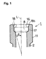
- FIG. 1 is an enlarged sectional view of a principal portion of a tubular member showing an introduction port portion
- Fig. 2 a front view of the glow plug with a right half portion thereof shown in section
- Fig. 3 an enlarged view of a principal portion of the glow plug.
- a glow plug 1 is roughly formed of a main metal member constituting a tubular member 2, a heating portion 3 fixed to a front end of the tubular member 2, and a central electrode constituting a shaft-like member 4.
- the heating portion 3 includes a sheath tube 301 obtained by forming a conductive metal to the shape of a cap, and a heating element 302 made of a conductive heating coil, the interior of the sheath tube 301 being packed with, for example, magnesia powder 303.
- the shaft-like member 4 extends through the center of the tubular member 2 to reach the sheath tube 301, and a front end of the shaft-like member and a tip of the sheath tube 301 are electrically connected together via a control coil 5 and a heating element 302.
- a stepped bore 8 is formed in an upper end of the tubular member 2, in an upper end of the tubular member 2, a stepped bore 8 is formed. Owing to a bush type insulating ring 9 fitted in the stepped bore 8, an upper portion of the shaft-like member 4 is supported on the center of the tubular member 2, and joint portions of the two members 4, 2 are electrically insulated from each other. Between the shaft-like member 4 and sheath tube 301, a rubber packing 10 is fitted, by which the joint portions of the shaft-like member and sheath tube are electrically insulated from each other, and with which the sheath tube 301 is sealed.
- a trunk portion at an upper end of the tubular member 2 is provided with a hexagonal bolt-shaped tool engaging section 11 on an outer circumference thereof, and a male thread 12 for fixing the glow plug to a diesel engine (not shown) is formed under the tool engaging section.
- the shaft-like member 4 is provided at a top portion thereof with a threaded section 13 to which a power source cable (not shown) is connected, and the insulating ring 9 is held firmly by a circular nut 14 screwed on the threaded section 13.
- the clearance 15 there is a clearance 15 between an inner surface of the stepped bore 8 of the tubular member 2 and an outer surface of the shaft-like member 4, and the clearance 15 is closed with an O-ring 16.
- the O-ring 16 of such a cross-sectional shape that has a width larger than that of the clearance 15 is fitted as shown in Fig. 3 in the same clearance between the inner surface of the stepped bore 8 of the tubular member 2 and outer surface of the shaft-like member 4, and held between a stepped portion of the stepped bore 8 and the insulating ring 9 to close the clearance 15.
- the features of the present invention reside in the formation of a seal region 17 on the stepped portion of the stepped bore to the height necessary to have the O-ring display a sealing effect well, the formation of an introduction port portion 18 opened in the shape of a rearwardly divergent cone extending from the seal region toward an opening of the stepped bore 8, and the setting of a cone angle ⁇ (refer to Fig. 1) of the introduction port portion 18 with respect to the axis L of the tubular member 2 to not larger than 35°.
- the axial length of the introduction port portion 18 is set to a level which permits the O-ring 16 set in the introduction port portion 18, and not yet forced down, to be sunk by at least a half portion thereof into the introduction port portion 18.
- the O-ring 16 and insulating ring 9 are fitted from an upper side around the shaft-like member 4 fixed to the tubular member 2, and the O-ring 16 is put in the seal region 17 of the stepped bore 8 as the O-ring is pressed down by the insulating ring 9. Since the portion of the O-ring the height of which is not smaller than a half of a total height thereof sinks naturally during this time into the opened end of the introduction port portion, the pressing of the O-ring into the stepped bore 8 can be started smoothly.
- the O-ring 16 is pressed by the insulating ring 9 and forced into the seal region 17 as the O-ring is deformed slowly along an inclined surface of the introduction port portion 18, so that the breakage of and cracks in the O-ring rarely occur.
- the O-ring 16 entering the seal region 17 closely contacts all of the inner circumference and upper surface of the stepped bore 8, the outer circumference of the shaft-like member 4 and a lower surface of the insulating ring 9 to completely close the clearance 15.
- glow plugs 1 in which the cone angles ⁇ of the introduction port portions 18 thereof were set to 45°, 35°, 25°, 20°, 10° and 5° were manufactured, and tests were conducted concerning the condition of the O-rings 16 already set in the seal region and the excellence and poorness of the sealability thereof.
- Concerning the stepped bore 8 and referring to Fig. 1, the inner diameter of the seal region 17, the diameter of the opened end, and the depth measured from the opened end to the upper surface of the stepped portion of the stepped bore 8 were set to 6 mm (+0.1 mm to -0.05 mm), 6.7 ⁇ 0.1 mm and 2.8 ⁇ 0.2 mm respectively.
- the diameter of the portion of the shaft-like member 4 which corresponded to the seal region 17 was set to 4 mm.
- the O-rings used in the tests were O-rings of 6.24 mm in outer diameter and 1.2 mm in diameter of a cross section thereof. These set levels correspond to those in the above-mentioned glow plug 1 having a nominal diameter of the male thread of 8 mm.
- the results of the tests will be shown in Table 1. Results of the O-ring Setting Tests: Cone angle ⁇ Condition of O-ring Sealability Breakage Cracking 45° 5% 12% O 35° 1% 5% O 25° 0% 2% O 20° 0% 0% 0% O 10° 0% 0% O 5° 0% 0% X
- FIG. 5 A second mode of embodiment of the present invention will be described with reference to Fig. 5 showing a glow plug as an example.
- Fig. 5 showing a glow plug as an example.
- a description thereof will be omitted by quoting the description of the corresponding parts of the mode 1 of embodiment.
- a tubular member (main metal member) 2 formed out of carbon steel has a through bore 203 extending axially between a front end 201 and a rear end 202 thereof.
- a heating portion 3 a rod-like shaft-like member 4 and a coiled lead 19 for connecting the heating portion and shaft-like member together are provided so that a front end side (lower end side in the drawing) of the heating portion 3 projects from the front end 201.
- a trunk portion 204 of the tubular member 2 is provided thereon with a male thread 12 of 10 mm in nominal diameter for fixing the glow plug to an engine and the like.
- a rear end portion of the tubular member 2 is provided thereon with a hexagonal tool engaging section 11 for engaging a tool, such as a wrench and the like therewith.
- the heating portion 3 is formed of a so-called ceramic heating element, which is formed by burying a heating element 304 made of a substantially U-shaped conductive ceramic material containing WC or MoSi 2 as a main component in a base member 305 made of an insulating ceramic material containing silicon nitride as a main component; and drawing out both end of the heating element 304 to side portions thereof by drawer leads 306, 307 made of tungsten.
- a front end section 304S in the vicinity of a front end (lower end) of the heating element 304 is formed to a diameter smaller than that of the other portion thereof. When an electric current is applied to the heating portion, mainly this front end section 304S generates heat to cause the front end region of the heating portion 3 to generate heat.
- the heating portion 3 is brazed to the tubular member 2 via an outer tube 20 brazed to the heating member 3 so as to surround the same. Owing to this arrangement, one end of the heating element 304 is electrically connected to the tubular member 2 via the drawer lead 306 and outer tube 20.
- the other end of the heating element 304 is drawn out to a rear end section 308 by the drawer lead 307, and both the rear end section 308 and a front end portion 401 of the shaft-like member 4 are electrically connected together by the coil lead 19 formed by winding a leader line helically and made of nickel.
- the shaft-like member 4 formed out of an Fe material containing Fe as a main component projects from the rear end 202 of the tubular member 2 in the rearward direction (upward direction in the drawing), and is retained so that the shaft-like member neither contacts nor electrically communicates with the tubular member 2, by the O-ring 16, which is fitted from the rear end 202 in a clearance between the inner surface of the through bore 203 and the outer surface of the shaft-like member 4, and by the insulating ring 9, the air-tightness of this clearance being also maintained.
- a rear end portion 402 of the shaft-like member 4 is covered with the outer terminal 21 and caulked in the circumferential direction thereof to form a caulked portion 211, the outer terminal 21 and shaft-like member 4 being thereby fixed to each other in one body.
- the modes 1 and 2 of embodiment of the present invention have been described above.
- the present invention is not, of course, limited to these modes of embodiment.
- a heater is the glow plug 1
- the present invention can be applied to any uses as long as an object apparatus is a water heater and the like adapted to heat an object material, such as a gas, a liquid, etc.
- the glow plug 1 shown in the mode 1 of embodiment is a temperature self-control type glow plug in which the control coil 5 and heating coil 105 are connected together in series
- the glow plug 1 shown in Fig. 4 which is not provided with the control coil 5 may also serve the purpose.
- the heating portion 3 in the mode 2 of embodiment was formed by burying the heating element 304 of a conductive ceramic material in the base member 305 of an insulating ceramic material. This heating portion 3 may also be formed by burying the same heating element 302 of a heating coil as is referred to in the mode 1 of embodiment in such a base member 305.
- the heating element 304 of a conductive ceramic material may be disposed so as to face onto a part (for example, the front end) of the surface of the base member 305.
- the cone angle ⁇ is set to a level in the range of 10° to 20° as in preferred aspect of the invention (2) above, a substantial rate of occurrence of damage to the O-ring of 0% can be attained. This enables the visual inspection of a just-set O-ring to be rendered unnecessary, and the automatic setting of the O-ring to be attained easily.
- the forcing of the O-ring into the stepped bore can be started smoothly.
Landscapes
- Engineering & Computer Science (AREA)
- Chemical & Material Sciences (AREA)
- Combustion & Propulsion (AREA)
- Mechanical Engineering (AREA)
- General Engineering & Computer Science (AREA)
- Resistance Heating (AREA)
Abstract
Description
- The present invention relates to a heater for heating an object material, such as a gas, a liquid and the like, and to a glow plug for a diesel engine.
- A related art heater will be described on the basis of Fig. 6 of the accompanying drawings taking as an example the glow plug disclosed in Japanese Patent Laid-Open No. 10-2557. This
glow plug 100 roughly includes a main metal member constituting atubular member 101, a captype sheath tube 102 fixed to a front end of thetubular member 101, and a central electrode constituting a shaft-like member 103. The shaft-like member 103 extends through the center of thetubular member 101 to reach thesheath tube 102, and a front end of thesheath tube 102 and that of the shaft-like member 103 are electrically connected to each other via acontrol coil 104 and aheating coil 105. Astepped bore 106 is formed in a rear end (upper portion of the drawing) of thetubular member 101, and an upper portion of the shaft-like member 103 is fixed in the center of thetubular member 101 by a bushtype insulating ring 107 fitted in thestepped bore 106. - Thus, the
glow plug 100 employs a seal structure having aclearance 108 between the surface of thetubular member 101 which defines thestepped bore 106 and the shaft-like member 103, an O-ring 109 being fitted in theclearance 108 and crushed by a stepped portion of thestepped bore 106 and theinsulating ring 107, theclearance 108 being thereby closed. - When the O-
ring 109 is inserted into thestepped bore 106 of theglow plug 100, there is the possibility that the O-ring 109 be broken or cracked, i.e., damaged. Especially, in recent years, the miniaturization of theglow plug 100 has progressed, and a glow plug in which a nominal diameter (diameter of a ridge) of amale thread 110 to be engaged with a diesel engine is not larger than 10 mm is being manufactured. In such a glow plug, astepped bore 106 has a small diameter, and an O-ring 109 is extremely small, so that the O-ring is in great danger of being damaged. Needless to say, the damage to the O-ring 109 causes an imperfect sealing of theglow plug 100 and exerts a bad influence upon the performance thereof. Therefore, it becomes essential to visually inspect the O-ring after the O-ring is inserted into the stepped bore, and this rendered it difficult to automate the O-ring setting operation. - The present invention has been made in view of the above-mentioned circumstances, and provides a heater and a glow plug which have a seal structure adapted to seal with an O-ring a clearance between an inner surface of a stepped bore in a tubular member and an outer surface of a shaft-like member inserted into the stepped bore, and which are capable of holding down a rate of occurrence of damage to the O-ring during an O-ring setting operation.
- The present invention (1) provides a heater having a seal structure formed by inserting a shaft-like member into a stepped bore made in a tubular member, and providing an O-ring on a stepped portion of the stepped bore so as to close a clearance between the shaft-like member and tubular member, wherein a seal region is formed on a stepped portion of the stepped bore, a conical introduction port portion extending divergently in the rearward direction from the seal region toward an opening of the stepped bore is formed, and a cone angle α of the introduction port portion with respect to the axis of the tubular member being set not larger than 35°.
- When the introduction port portion of a cone angle of not larger than α=35° is formed in the stepped bore as mentioned above, the O-ring is forced into the seal region as the O-ring is deformed slowly, so that the breakage and cracking of the O-ring rarely occur. When the cone angle α is set in the range of 10° to 20°, which structure will hereinafter be referred to as preferred aspect of the invention (2), a substantial rate of occurrence of damage to the O-ring of 0% becomes possible to be attained. It is preferable that the axial length of the introduction port portion be set to a level which permits the O-ring set in the introduction port portion, and not yet forced down, to be sunk by at least a half portion thereof into the introduction port portion, which structure will hereinafter be referred to as preferred aspect of the invention (3). This enables the O-ring to be forced into the stepped bore smoothly.
- Embodiments of the invention will now be described, by way of example only, with reference to the accompanying drawings in which:-
- Fig. 1 is an enlarged sectional view of principal portion of an introduction port portion of a tubular member;
- Fig. 2 is a front view of a glow plug with a right half portion thereof shown in section;
- Fig. 3 is an enlarged sectional view of a principal portion of the glow plug;
- Fig. 4 is a partial enlarged sectional view showing another mode of heating portion of the glow plug;
- Fig. 5 is a longitudinal sectional view showing a second mode of embodiment of the glow plug; and
- Fig. 6 is a sectional view showing a related art glow plug.
-
- A first mode of embodiment of the present invention will now be described with reference to Figs. 1 to 3 with a glow plug illustrated as an example. Fig. 1 is an enlarged sectional view of a principal portion of a tubular member showing an introduction port portion, Fig. 2 a front view of the glow plug with a right half portion thereof shown in section, and Fig. 3 an enlarged view of a principal portion of the glow plug.
- A
glow plug 1 is roughly formed of a main metal member constituting atubular member 2, aheating portion 3 fixed to a front end of thetubular member 2, and a central electrode constituting a shaft-like member 4. Theheating portion 3 includes asheath tube 301 obtained by forming a conductive metal to the shape of a cap, and aheating element 302 made of a conductive heating coil, the interior of thesheath tube 301 being packed with, for example,magnesia powder 303. The shaft-like member 4 extends through the center of thetubular member 2 to reach thesheath tube 301, and a front end of the shaft-like member and a tip of thesheath tube 301 are electrically connected together via acontrol coil 5 and aheating element 302. - In an upper end of the
tubular member 2, astepped bore 8 is formed. Owing to a bushtype insulating ring 9 fitted in thestepped bore 8, an upper portion of the shaft-like member 4 is supported on the center of thetubular member 2, and joint portions of the twomembers like member 4 andsheath tube 301, arubber packing 10 is fitted, by which the joint portions of the shaft-like member and sheath tube are electrically insulated from each other, and with which thesheath tube 301 is sealed. - A trunk portion at an upper end of the
tubular member 2 is provided with a hexagonal bolt-shapedtool engaging section 11 on an outer circumference thereof, and amale thread 12 for fixing the glow plug to a diesel engine (not shown) is formed under the tool engaging section. The shaft-like member 4 is provided at a top portion thereof with a threadedsection 13 to which a power source cable (not shown) is connected, and theinsulating ring 9 is held firmly by acircular nut 14 screwed on the threadedsection 13. - There is a clearance 15 between an inner surface of the
stepped bore 8 of thetubular member 2 and an outer surface of the shaft-like member 4, and the clearance 15 is closed with an O-ring 16. Namely, the O-ring 16 of such a cross-sectional shape that has a width larger than that of the clearance 15 is fitted as shown in Fig. 3 in the same clearance between the inner surface of thestepped bore 8 of thetubular member 2 and outer surface of the shaft-like member 4, and held between a stepped portion of thestepped bore 8 and theinsulating ring 9 to close the clearance 15. - Thus, the features of the present invention reside in the formation of a
seal region 17 on the stepped portion of the stepped bore to the height necessary to have the O-ring display a sealing effect well, the formation of anintroduction port portion 18 opened in the shape of a rearwardly divergent cone extending from the seal region toward an opening of thestepped bore 8, and the setting of a cone angle α (refer to Fig. 1) of theintroduction port portion 18 with respect to the axis L of thetubular member 2 to not larger than 35°. In this structure, the axial length of theintroduction port portion 18 is set to a level which permits the O-ring 16 set in theintroduction port portion 18, and not yet forced down, to be sunk by at least a half portion thereof into theintroduction port portion 18. In other words, when the O-ring 16 is set in theintroduction port portion 18, and not yet forced down, less than half of the O-ring protrudes above the upper end of thetubular member 2. Anedge 18c of an end of the opening of theintroduction port portion 18 is chamfered for the purpose of preventing the O-ring 16 from being damaged. - A method of setting the O-ring in the introduction port portion will now be described. Before setting the O-
ring 16, the shaft-like member 4 is inserted into and fixed in thetubular member 2. However, since the shaft member inserting and fixing step is carried out in the same manner as the corresponding step carried out in the production of a related art glow plug, so that a description thereof will be omitted. - First, the O-
ring 16 and insulatingring 9 are fitted from an upper side around the shaft-like member 4 fixed to thetubular member 2, and the O-ring 16 is put in theseal region 17 of thestepped bore 8 as the O-ring is pressed down by the insulatingring 9. Since the portion of the O-ring the height of which is not smaller than a half of a total height thereof sinks naturally during this time into the opened end of the introduction port portion, the pressing of the O-ring into thestepped bore 8 can be started smoothly. The O-ring 16 is pressed by theinsulating ring 9 and forced into theseal region 17 as the O-ring is deformed slowly along an inclined surface of theintroduction port portion 18, so that the breakage of and cracks in the O-ring rarely occur. The O-ring 16 entering theseal region 17 closely contacts all of the inner circumference and upper surface of thestepped bore 8, the outer circumference of the shaft-like member 4 and a lower surface of theinsulating ring 9 to completely close the clearance 15. - In order to verify the effect of the present invention,
glow plugs 1 in which the cone angles α of theintroduction port portions 18 thereof were set to 45°, 35°, 25°, 20°, 10° and 5° were manufactured, and tests were conducted concerning the condition of the O-rings 16 already set in the seal region and the excellence and poorness of the sealability thereof. Concerning thestepped bore 8 and referring to Fig. 1, the inner diameter of theseal region 17, the diameter of the opened end, and the depth measured from the opened end to the upper surface of the stepped portion of thestepped bore 8 were set to 6 mm (+0.1 mm to -0.05 mm), 6.7±0.1mm and 2.8±0.2mm respectively. The diameter of the portion of the shaft-like member 4 which corresponded to theseal region 17 was set to 4 mm. The O-rings used in the tests were O-rings of 6.24 mm in outer diameter and 1.2 mm in diameter of a cross section thereof. These set levels correspond to those in the above-mentionedglow plug 1 having a nominal diameter of the male thread of 8 mm. The results of the tests will be shown in Table 1.Results of the O-ring Setting Tests: Cone angle α Condition of O-ring Sealability Breakage Cracking 45° 5% 12% O 35° 1% 5% O 25° 0% 2% O 20° 0% 0% O 10° 0% 0% O 5° 0% 0% X - As is clear from these results of the tests, the O-
ring 16 was damaged with a high percentage of 17% when the cone angle was α=45° but, when the cone angle was α=35°, the rate of occurrence of damage to the O-ring greatly decreased. Furthermore, when the cone angle was not larger than α=20°, the rate of occurrence of damage became 0%. When the cone angle was α=5°, an imperfect sealing of the glow plug occurred for the reason that the depth of theintroduction port portion 18 increased to cause that of theseal region 17 to become short since the depth of thestepped bore 8 is limited. Therefore, in the case where, even when the depth of thestepped bore 8 is increased, anecessary seal region 17 can be secured, a necessary sealability can be secured even when the cone angle is α=5° or not larger than α=5°. - A second mode of embodiment of the present invention will be described with reference to Fig. 5 showing a glow plug as an example. Regarding the parts having reference numerals as shown in Fig. 5 which are identical with those of the parts of the mode of
embodiment 1, and which are not described below, a description thereof will be omitted by quoting the description of the corresponding parts of themode 1 of embodiment. - A tubular member (main metal member) 2 formed out of carbon steel has a
through bore 203 extending axially between afront end 201 and arear end 202 thereof. In this throughbore 203, aheating portion 3, a rod-like shaft-like member 4 and acoiled lead 19 for connecting the heating portion and shaft-like member together are provided so that a front end side (lower end side in the drawing) of theheating portion 3 projects from thefront end 201. Atrunk portion 204 of thetubular member 2 is provided thereon with amale thread 12 of 10 mm in nominal diameter for fixing the glow plug to an engine and the like. A rear end portion of thetubular member 2 is provided thereon with a hexagonaltool engaging section 11 for engaging a tool, such as a wrench and the like therewith. - The
heating portion 3 is formed of a so-called ceramic heating element, which is formed by burying aheating element 304 made of a substantially U-shaped conductive ceramic material containing WC or MoSi2 as a main component in abase member 305 made of an insulating ceramic material containing silicon nitride as a main component; and drawing out both end of theheating element 304 to side portions thereof by drawer leads 306, 307 made of tungsten. Afront end section 304S in the vicinity of a front end (lower end) of theheating element 304 is formed to a diameter smaller than that of the other portion thereof. When an electric current is applied to the heating portion, mainly thisfront end section 304S generates heat to cause the front end region of theheating portion 3 to generate heat. - The
heating portion 3 is brazed to thetubular member 2 via anouter tube 20 brazed to theheating member 3 so as to surround the same. Owing to this arrangement, one end of theheating element 304 is electrically connected to thetubular member 2 via thedrawer lead 306 andouter tube 20. - In the meantime, the other end of the
heating element 304 is drawn out to arear end section 308 by thedrawer lead 307, and both therear end section 308 and afront end portion 401 of the shaft-like member 4 are electrically connected together by thecoil lead 19 formed by winding a leader line helically and made of nickel. - The shaft-
like member 4 formed out of an Fe material containing Fe as a main component projects from therear end 202 of thetubular member 2 in the rearward direction (upward direction in the drawing), and is retained so that the shaft-like member neither contacts nor electrically communicates with thetubular member 2, by the O-ring 16, which is fitted from therear end 202 in a clearance between the inner surface of the throughbore 203 and the outer surface of the shaft-like member 4, and by the insulatingring 9, the air-tightness of this clearance being also maintained. In addition, arear end portion 402 of the shaft-like member 4 is covered with theouter terminal 21 and caulked in the circumferential direction thereof to form a caulkedportion 211, theouter terminal 21 and shaft-like member 4 being thereby fixed to each other in one body. - When a voltage is applied between the
outer terminal 21 andtubular member 2 in thisglow plug 1, an electric current flows from theouter terminal 21 to thetubular member 2 through the shaft-like member 4, coiledlead 19,drawer lead 307,heating element 304,drawer lead 306 andouter tube 20 to cause thefront end section 304S of theheating element 304 to generate heat. - The
modes modes glow plug 1 is described. The present invention can be applied to any uses as long as an object apparatus is a water heater and the like adapted to heat an object material, such as a gas, a liquid, etc. Although theglow plug 1 shown in themode 1 of embodiment is a temperature self-control type glow plug in which thecontrol coil 5 andheating coil 105 are connected together in series, theglow plug 1 shown in Fig. 4 which is not provided with thecontrol coil 5 may also serve the purpose. - The
heating portion 3 in themode 2 of embodiment was formed by burying theheating element 304 of a conductive ceramic material in thebase member 305 of an insulating ceramic material. Thisheating portion 3 may also be formed by burying thesame heating element 302 of a heating coil as is referred to in themode 1 of embodiment in such abase member 305. Theheating element 304 of a conductive ceramic material may be disposed so as to face onto a part (for example, the front end) of the surface of thebase member 305. - In the heater or glow plug according to the present invention, an introduction port portion of a cone angle of not larger than α=35° is formed in the stepped bore. Therefore, the O-ring is forced into the seal region as the O-ring is deformed slowly, so that the O-ring is rarely damaged. When the cone angle α is set to a level in the range of 10° to 20° as in preferred aspect of the invention (2) above, a substantial rate of occurrence of damage to the O-ring of 0% can be attained. This enables the visual inspection of a just-set O-ring to be rendered unnecessary, and the automatic setting of the O-ring to be attained easily.
- When the axial length of the introduction port portion is set to a level which permits the O-ring set in the introduction port portion and not yet forced down to be sunk by at least a half portion thereof into the introduction port portion as in preferred aspect of the invention (3) above, the forcing of the O-ring into the stepped bore can be started smoothly.
- This effect is noticeable when the heater is utilized as a glow plug with the nominal diameter of the male thread for fixing the flow plug to an engine set not larger than 10 mm, and a more advantageous effect is displayed as this nominal diameter decreases to as small as not larger than 8 mm.
Claims (10)
- A heater having a seal structure formed by inserting a shaft-like member (4) into a stepped bore ((8) made in a tubular member (2), and providing an O-ring (16) on a stepped portion of the stepped bore (8) so as to close a clearance (15) between the shaft-like member (4) and tubular member (2),
wherein a seal region (17) is formed on a stepped portion of the stepped bore (8), and characterized in that a conical introduction port portion (18) is formed which extends divergently in the rearward direction from the seal region (17) toward an opening of the stepped bore (8), and wherein a cone angle (α) of the introduction port portion (18) with respect to an axis (L) of the tubular member (2) is not larger than 35°. - A heater according to claim 1, wherein the cone angle (α) is in the range of from 10° to 20°.
- A heater according to claim 1 or 2, wherein the axial length of the introduction port portion (18) is set to a level which permits the O-ring (16) set in the introduction port portion (18), and not yet forced down, to be sunk by at least a half portion thereof into the introduction port portion (18).
- A heater according to one of claims 1 to 3, wherein a heating portion (3) of the heater comprises a ceramic material.
- A heater according to one of claims 1 to 4, wherein the heating portion is of a sheath type including a sheath tube (301) provided on a front end of the tubular member (2), and a heating element (302) provided in the interior of the sheath tube.
- A heater according to claim 4, wherein the heating portion includes a base member (305) formed out of an insulating ceramic material, and a heating element (304) buried in the base member and formed out of a conductive ceramic material.
- A heater according to claim 4, wherein the heating portion includes a base member (305) formed out of an insulating ceramic material, and a heating element (302) buried in the interior of the base member (305) and formed of a conductive heating coil.
- A heater according to claim 4, wherein the heating portion includes a base member (305) formed out of an insulating ceramic material, and a heating element (304) formed so as to face onto a part of a surface of the base member (305) and made of a conductive ceramic material.
- A glow plug comprising the heater according to one of claims 1 to 8, wherein a male thread (12) for fixing the glow plug to an engine is formed on an outer circumference of a trunk portion (204) of the tubular member (2), a nominal diameter of the male thread (12) being set not larger than 10 mm.
- A glow plug according to claim 9, wherein a nominal diameter of the male thread (12) is set not larger than 8 mm.
Applications Claiming Priority (2)
| Application Number | Priority Date | Filing Date | Title |
|---|---|---|---|
| JP2001175378 | 2001-06-11 | ||
| JP2001175378A JP2002367760A (en) | 2001-06-11 | 2001-06-11 | Heater and glow plug |
Publications (2)
| Publication Number | Publication Date |
|---|---|
| EP1267126A2 true EP1267126A2 (en) | 2002-12-18 |
| EP1267126A3 EP1267126A3 (en) | 2006-11-08 |
Family
ID=19016526
Family Applications (1)
| Application Number | Title | Priority Date | Filing Date |
|---|---|---|---|
| EP02254017A Withdrawn EP1267126A3 (en) | 2001-06-11 | 2002-06-10 | Heater and glow plug |
Country Status (3)
| Country | Link |
|---|---|
| US (1) | US6627854B2 (en) |
| EP (1) | EP1267126A3 (en) |
| JP (1) | JP2002367760A (en) |
Cited By (1)
| Publication number | Priority date | Publication date | Assignee | Title |
|---|---|---|---|---|
| EP2434220A3 (en) * | 2010-09-16 | 2017-12-13 | Ngk Spark Plug Co., Ltd. | Glow plug and method of manufacturing the same |
Families Citing this family (12)
| Publication number | Priority date | Publication date | Assignee | Title |
|---|---|---|---|---|
| DE10128656A1 (en) * | 2001-06-15 | 2003-01-02 | Beru Ag | Glow plug and process for its manufacture |
| US6696670B1 (en) * | 2002-12-03 | 2004-02-24 | O'donnell Steven B. | Glow plug with tightly-fit electrode |
| JP2005273955A (en) * | 2004-03-23 | 2005-10-06 | Ngk Spark Plug Co Ltd | Seeds type glow plug and manufacturing method thereof |
| JP4481769B2 (en) * | 2004-03-31 | 2010-06-16 | 日立オートモティブシステムズ株式会社 | Disc brake |
| JP2007205248A (en) * | 2006-02-01 | 2007-08-16 | Fuji Koki Corp | Control valve for variable displacement compressor |
| US7329836B2 (en) * | 2006-03-30 | 2008-02-12 | Ngk Spark Plug Co., Ltd. | Glow plug with O-ring seal |
| JP4960118B2 (en) * | 2006-03-30 | 2012-06-27 | 日本特殊陶業株式会社 | Glow plug |
| DE102008009429A1 (en) * | 2007-03-15 | 2008-09-18 | Robert Bosch Gmbh | Seal for a glow plug |
| US20100078421A1 (en) * | 2008-10-01 | 2010-04-01 | Federal-Mogul Italy Sr1 | Glow plug adn heater assembly therefor with an improved connection between a central electrode and a heater probe of the heater assembly |
| JP5639227B2 (en) * | 2013-06-13 | 2014-12-10 | 日本特殊陶業株式会社 | Glow plug |
| JP6426346B2 (en) * | 2014-01-16 | 2018-11-21 | 日本特殊陶業株式会社 | Glow plug |
| DE102016108592B4 (en) * | 2016-05-10 | 2018-06-28 | Borgwarner Ludwigsburg Gmbh | Glow plug and method of manufacturing a glow plug |
Citations (1)
| Publication number | Priority date | Publication date | Assignee | Title |
|---|---|---|---|---|
| JPH102557A (en) | 1996-06-14 | 1998-01-06 | Ngk Spark Plug Co Ltd | Self-control type seeds glow plug |
Family Cites Families (14)
| Publication number | Priority date | Publication date | Assignee | Title |
|---|---|---|---|---|
| GB876300A (en) * | 1958-11-13 | 1961-08-30 | Bosch Gmbh Robert | Improvements in or relating to glow plugs for internal combustion engines |
| JPS60254586A (en) * | 1984-05-30 | 1985-12-16 | 株式会社デンソー | Ceramic heater |
| DE3502525C2 (en) * | 1985-01-25 | 1993-11-11 | Beru Werk Ruprecht Gmbh Co A | Glow element |
| GB2206378A (en) * | 1987-06-19 | 1989-01-05 | Secretary Trade Ind Brit | Fuel injection arrangement |
| JPH0339819A (en) | 1989-07-05 | 1991-02-20 | Rinnai Corp | Controller with remote operator |
| JPH03175210A (en) * | 1989-09-11 | 1991-07-30 | Jidosha Kiki Co Ltd | Glow plug of ceramic heater type |
| JP2852552B2 (en) * | 1990-04-16 | 1999-02-03 | 自動車機器株式会社 | Sheath heater and method of manufacturing the same |
| JPH04143518A (en) * | 1990-10-04 | 1992-05-18 | Ngk Spark Plug Co Ltd | Self-regulative type ceramic glow plug |
| DE4133338A1 (en) * | 1991-10-08 | 1993-04-15 | Beru Werk Ruprecht Gmbh Co A | GLOW PLUG |
| JP3039819B2 (en) | 1992-01-10 | 2000-05-08 | 株式会社デンソー | Glow plug |
| JP3802599B2 (en) * | 1995-12-28 | 2006-07-26 | 日本特殊陶業株式会社 | Electrically heated sheathed heater and self-temperature control type glow plug |
| US6064039A (en) * | 1998-04-15 | 2000-05-16 | Ngk Spark Plug Co., Ltd. | Glow plug with small-diameter sheath tube enclosing heating and control coils |
| DE60000519T2 (en) * | 1999-02-25 | 2003-01-30 | Ngk Spark Plug Co., Ltd. | Glow plug and spark plug, and their manufacturing process |
| JP2002098333A (en) * | 2000-09-26 | 2002-04-05 | Ngk Spark Plug Co Ltd | Glow plug |
-
2001
- 2001-06-11 JP JP2001175378A patent/JP2002367760A/en active Pending
-
2002
- 2002-06-10 EP EP02254017A patent/EP1267126A3/en not_active Withdrawn
- 2002-06-10 US US10/164,380 patent/US6627854B2/en not_active Expired - Lifetime
Patent Citations (1)
| Publication number | Priority date | Publication date | Assignee | Title |
|---|---|---|---|---|
| JPH102557A (en) | 1996-06-14 | 1998-01-06 | Ngk Spark Plug Co Ltd | Self-control type seeds glow plug |
Cited By (1)
| Publication number | Priority date | Publication date | Assignee | Title |
|---|---|---|---|---|
| EP2434220A3 (en) * | 2010-09-16 | 2017-12-13 | Ngk Spark Plug Co., Ltd. | Glow plug and method of manufacturing the same |
Also Published As
| Publication number | Publication date |
|---|---|
| US6627854B2 (en) | 2003-09-30 |
| JP2002367760A (en) | 2002-12-20 |
| US20020195436A1 (en) | 2002-12-26 |
| EP1267126A3 (en) | 2006-11-08 |
Similar Documents
| Publication | Publication Date | Title |
|---|---|---|
| US6627854B2 (en) | Heater and glow plug | |
| US8013504B2 (en) | Spark plug for internal combustion engine and method for producing the spark plug | |
| US8624473B2 (en) | Spark plug | |
| US8633640B2 (en) | Spark plug | |
| US6744015B2 (en) | Heater and method for manufacturing the same | |
| US20100264804A1 (en) | Spark plug | |
| JPH059698B2 (en) | ||
| CN103262369B (en) | Spark plug | |
| US4087904A (en) | Method to manufacture glow plugs, particularly to secure glow elements in sockets | |
| US7944134B2 (en) | Spark plug with center electrode having high heat dissipation property | |
| JP2012506988A (en) | Glow plug with improved seal, heater probe assembly therefor and method of construction thereof | |
| US4952837A (en) | Surface gap type igniter plug | |
| KR101998536B1 (en) | spark plug | |
| JP2009545856A (en) | Spark plug with threaded part at high position of integral shell | |
| US4182009A (en) | Electrical igniters | |
| US20050194369A1 (en) | Electrically heatable glow plug and method for manufacturing an electrically heatable glow plug | |
| US5022881A (en) | Method for making a spark plug with a predetermined spark gap | |
| EP2226912A1 (en) | Spark plug | |
| US4592134A (en) | Glow plug | |
| JP6942159B2 (en) | Spark plug | |
| EP3200291A1 (en) | Spark plug | |
| US12088067B2 (en) | Spark plug | |
| EP0113542A1 (en) | A thermocouple | |
| US4643688A (en) | Method for assembling a spark plug | |
| EP3441672B1 (en) | Glow plug |
Legal Events
| Date | Code | Title | Description |
|---|---|---|---|
| PUAI | Public reference made under article 153(3) epc to a published international application that has entered the european phase |
Free format text: ORIGINAL CODE: 0009012 |
|
| AK | Designated contracting states |
Kind code of ref document: A2 Designated state(s): AT BE CH CY DE DK ES FI FR GB GR IE IT LI LU MC NL PT SE TR |
|
| AX | Request for extension of the european patent |
Free format text: AL;LT;LV;MK;RO;SI |
|
| PUAL | Search report despatched |
Free format text: ORIGINAL CODE: 0009013 |
|
| AK | Designated contracting states |
Kind code of ref document: A3 Designated state(s): AT BE CH CY DE DK ES FI FR GB GR IE IT LI LU MC NL PT SE TR |
|
| AX | Request for extension of the european patent |
Extension state: AL LT LV MK RO SI |
|
| AKX | Designation fees paid | ||
| REG | Reference to a national code |
Ref country code: DE Ref legal event code: 8566 |
|
| STAA | Information on the status of an ep patent application or granted ep patent |
Free format text: STATUS: THE APPLICATION IS DEEMED TO BE WITHDRAWN |
|
| 18D | Application deemed to be withdrawn |
Effective date: 20070509 |