EP1267066A2 - Enbloc device for filtering the intake air of combustion engines - Google Patents
Enbloc device for filtering the intake air of combustion engines Download PDFInfo
- Publication number
- EP1267066A2 EP1267066A2 EP01130961A EP01130961A EP1267066A2 EP 1267066 A2 EP1267066 A2 EP 1267066A2 EP 01130961 A EP01130961 A EP 01130961A EP 01130961 A EP01130961 A EP 01130961A EP 1267066 A2 EP1267066 A2 EP 1267066A2
- Authority
- EP
- European Patent Office
- Prior art keywords
- filtering
- edges
- enbloc
- fixed
- support mean
- Prior art date
- Legal status (The legal status is an assumption and is not a legal conclusion. Google has not performed a legal analysis and makes no representation as to the accuracy of the status listed.)
- Granted
Links
Images


Classifications
-
- B—PERFORMING OPERATIONS; TRANSPORTING
- B01—PHYSICAL OR CHEMICAL PROCESSES OR APPARATUS IN GENERAL
- B01D—SEPARATION
- B01D46/00—Filters or filtering processes specially modified for separating dispersed particles from gases or vapours
- B01D46/52—Particle separators, e.g. dust precipitators, using filters embodying folded corrugated or wound sheet material
- B01D46/521—Particle separators, e.g. dust precipitators, using filters embodying folded corrugated or wound sheet material using folded, pleated material
- B01D46/522—Particle separators, e.g. dust precipitators, using filters embodying folded corrugated or wound sheet material using folded, pleated material with specific folds, e.g. having different lengths
-
- B—PERFORMING OPERATIONS; TRANSPORTING
- B01—PHYSICAL OR CHEMICAL PROCESSES OR APPARATUS IN GENERAL
- B01D—SEPARATION
- B01D46/00—Filters or filtering processes specially modified for separating dispersed particles from gases or vapours
- B01D46/0002—Casings; Housings; Frame constructions
- B01D46/0004—Details of removable closures, lids, caps or filter heads
-
- F—MECHANICAL ENGINEERING; LIGHTING; HEATING; WEAPONS; BLASTING
- F02—COMBUSTION ENGINES; HOT-GAS OR COMBUSTION-PRODUCT ENGINE PLANTS
- F02M—SUPPLYING COMBUSTION ENGINES IN GENERAL WITH COMBUSTIBLE MIXTURES OR CONSTITUENTS THEREOF
- F02M35/00—Combustion-air cleaners, air intakes, intake silencers, or induction systems specially adapted for, or arranged on, internal-combustion engines
- F02M35/02—Air cleaners
- F02M35/024—Air cleaners using filters, e.g. moistened
-
- B—PERFORMING OPERATIONS; TRANSPORTING
- B01—PHYSICAL OR CHEMICAL PROCESSES OR APPARATUS IN GENERAL
- B01D—SEPARATION
- B01D2271/00—Sealings for filters specially adapted for separating dispersed particles from gases or vapours
- B01D2271/02—Gaskets, sealings
-
- B—PERFORMING OPERATIONS; TRANSPORTING
- B01—PHYSICAL OR CHEMICAL PROCESSES OR APPARATUS IN GENERAL
- B01D—SEPARATION
- B01D2279/00—Filters adapted for separating dispersed particles from gases or vapours specially modified for specific uses
- B01D2279/60—Filters adapted for separating dispersed particles from gases or vapours specially modified for specific uses for the intake of internal combustion engines or turbines
Definitions
- the present invention relates to filters for filtering the intake air of combustion engines.
- the present invention refers to an enbloc device for filtering the intake air of internal combustion, supercharged and aspirated, engines especially with high performances and fit for being assembled into a related housing carried out in an intake duct.
- cylindrical or conical air filters fit to be fixed to an intake duct or enclosed into a casing with inlet openings for the ambient air and connected to a related intake duct.
- a polyurethan molding including the perimetric portion of the filtering element generally carries out the support.
- Another drawback consists in that the high reduction of the air flow through the filter caused by the high resistance of the polyester or paper filtering elements which further have the so-called “sponge effect” that causes technical problems to the sports engines due to humidity.
- the fibers of the filtering layer are soaked with low viscosity oil.
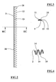
- the filtering element 2 is corrugated and has parallel folds following an approximately sinusoidal or zig-zag profile with rounded vertexes and has a plan approximately reproducing the shape of a housing for the device 1, carried out in an engine intake duct.
- the support mean 9 includes two annular shaped elements, first 3 and second 4, reproducing the plan perimeter of the filtering element 2 and respectively having a shaped edge, first 21 and second 22, almost complementary and reproducing, the peripheral corrugated profile of the filtering element 2.
- the shaped edges, first 21 and second 22, have a plurality of rounded recesses 13 and points 12 with related bending radiuses respectively equal or bigger and equal or lower than the bending radius of the corresponding corrugated sections of the filtering element 2.
- the recesses 13 and the points 12 are filleted by nearly rectilinear sections of the respective shaped edges, first 21 and second 22, for reproducing the zig-zag profile of the filtering element 2 folds.
- Said shape of the elements first 3 and second 4 allows a perfect joining between these latter and the median perimetric portion of the filtering element 2.
- the elements first 3 and second 4 of the support mean 9 are made of composite material with carbon fibers, Kevlar or fiber glass in a matrix of epoxidic synthetic resin.
- the enbloc fixings or assembling between the elements first 3 and second 4 of the support mean 9 with the perimetric portion of the filtering element 2 are carried out by means of a two-component adhesive 8 of polymerized epoxidic type and hardened in autoclave at controlled temperatures and pressures.
- the first element 3 of the support mean 9 has a housing 10, consisting of a peripheral groove, for sealing means 11 which substantially consists of an annular gasket made of elastic, high temperature and hydrocarbon proof material, of the type so-called O-Ring.
- the second element 4 of the support mean 9 has a plurality of fixing means 6, each one consisting of a protruding flange with a hole 7.
- the operation of the device 1 provides that this latter is positioned in correspondence of the related housing carried out in the engine intake duct and is fixed to said housing by means of screws or pins engaged in the holes 7.
- the dust particles and the foreign matters carried away by the air flow are held back by the filtering layer 15 and the oil.
- the main advantage of the present invention is to provide an enbloc device for filtering the intake air of internal combustion engines extremely strong and reliable, suitable to withstand typical mechanical stress of the race vehicles and temperatures up to about 250° C and at the same time light and fit for reducing the air flow resistances, having a wide surface of the filtering element.
Landscapes
- Chemical & Material Sciences (AREA)
- Engineering & Computer Science (AREA)
- Chemical Kinetics & Catalysis (AREA)
- Combustion & Propulsion (AREA)
- Mechanical Engineering (AREA)
- General Engineering & Computer Science (AREA)
- Filtering Of Dispersed Particles In Gases (AREA)
- Filtering Materials (AREA)
- Lubrication Details And Ventilation Of Internal Combustion Engines (AREA)
Abstract
Description
- figure 1 shows an axonometric view of the device object of the present invention;
- figure 2 shows 1 a side view of a first element of the figure 1 device;
- figure 3 shows a section view according to the plan III-III of figure 2;
- figure 4 shows a partial enlarged section view of a filtering element of figure 1;
- figure 5 shows a side view of a second element of the figure 1 device;
- figures from 6 to 8 show respectively plan, front and longitudinal section views of a variant of the figure 1 device.
Claims (14)
- Enbloc device for filtering the intake air of combustion engines including a filtering element (2) corrugated and peripherally fixed to a support mean (9), said device (1) being characterized in that the support mean (9) includes at least a first element (3) and at least a second element (4) respectively having a first shaped edge (21) and a second shaped edge (22) for reproducing the peripheral profile of the filtering element (2) and fixed to this latter in single block.
- Device according to the claim 1 characterized in that the shaped edges, first (21) and second (22), have a plurality of recesses (13) and points (12) having related bending radiuses respectively equal or greater and equal or lower than the bending radius of the corresponding corrugated sections of the filtering element (2).
- Device according to claim 2 characterized in that the points (12) and the recesses (13) are fillet by almost rectilinear sections of the respective shaped edges, first (21) and second (22).
- Device according to claim 1 characterized in that the elements, first (3) and second (4), of the support mean (9) are annular.
- Device according to claim 1 characterized in that at least one of the elements, first (3) and second (4), of the support mean (9) has a housing (10) for sealing means (11).
- Device according to claim 5 characterized in that the sealing means (11) consist of an O-Ring type gasket.
- Device according to claim 1 characterized in that at least one of the elements, first (3) and second (4), of the support mean (9) has a plurality of fixing means (6).
- Device according to claim 7 characterized in that each fixing mean (6) has at least a hole (7).
- Device according to claim 1 characterized in that the support mean (9) includes a couple of prismatic elements (20) fit to be fixed in a single block with respective rectilinear edges of the filtering element (2) whose corrugated edges are enbloc fixed to two edges of the at least first element (3) and to two edges of the at least second element (4), the ends of the prismatic elements (20), first (3) and second (4), being fixed in a single block.
- Device according to any of the preceding claims characterized in that the filtering element (2) includes two net layers (14) between which a filtering layer (15) is interposed.
- Device according to claim 10 characterized in that the net layers (14) are made of metal or composite synthetic material and the filtering layer (15) is made of cotton fibers or natural fibers or woven or nonwoven synthetic fibers and soaked with low viscosity oil.
- Device according to any of the preceding claims characterized in that the support mean (9) is made at least of carbon fibers or Kevlar of fiberglass in a matrix of synthetic resin.
- Device according to any of the preceding claims characterized in that the enbloc fixings are carried out by means of a two-component adhesive (8).
- Device according to any of the preceding claims characterized in that the fixings with two-component adhesive (8) are hardened in autoclave.
Applications Claiming Priority (2)
| Application Number | Priority Date | Filing Date | Title |
|---|---|---|---|
| IT2001BO000369A ITBO20010369A1 (en) | 2001-06-11 | 2001-06-11 | SINGLE BODY FILTERING DEVICES FOR THE AIR SUPPLY OF COMBUSTION ENGINES |
| ITBO010369 | 2001-06-11 |
Publications (3)
| Publication Number | Publication Date |
|---|---|
| EP1267066A2 true EP1267066A2 (en) | 2002-12-18 |
| EP1267066A3 EP1267066A3 (en) | 2003-05-14 |
| EP1267066B1 EP1267066B1 (en) | 2009-04-08 |
Family
ID=11439414
Family Applications (1)
| Application Number | Title | Priority Date | Filing Date |
|---|---|---|---|
| EP01130961A Expired - Lifetime EP1267066B1 (en) | 2001-06-11 | 2001-12-28 | Enbloc device for filtering the intake air of combustion engines |
Country Status (4)
| Country | Link |
|---|---|
| US (1) | US20020184863A1 (en) |
| EP (1) | EP1267066B1 (en) |
| DE (1) | DE60138272D1 (en) |
| IT (1) | ITBO20010369A1 (en) |
Cited By (1)
| Publication number | Priority date | Publication date | Assignee | Title |
|---|---|---|---|---|
| EP1577533A3 (en) * | 2004-03-17 | 2009-04-08 | Bmc S.R.L. | Air filter device |
Families Citing this family (5)
| Publication number | Priority date | Publication date | Assignee | Title |
|---|---|---|---|---|
| WO2005026522A1 (en) * | 2003-09-08 | 2005-03-24 | K & N Engineering, Inc. | Air box lid having an integrated filter |
| USD577110S1 (en) * | 2007-05-21 | 2008-09-16 | Mcdonald Michael | Air cleaner |
| US8343251B2 (en) * | 2008-04-14 | 2013-01-01 | Columbus Industries, Inc. | Composite filter media |
| JP6566861B2 (en) * | 2015-12-25 | 2019-08-28 | 株式会社やまびこ | Air cleaner for portable work engine |
| CN112392632A (en) * | 2020-11-10 | 2021-02-23 | 一汽解放汽车有限公司 | Oil bath type air filter |
Family Cites Families (5)
| Publication number | Priority date | Publication date | Assignee | Title |
|---|---|---|---|---|
| GB1075376A (en) * | 1964-09-21 | 1967-07-12 | Gen Motors Ltd | Gas filter elements |
| US3486626A (en) * | 1968-02-01 | 1969-12-30 | Sam Close | Replaceable medium,extended area filter unit |
| US4878930A (en) * | 1984-03-15 | 1989-11-07 | W. L. Gore & Associates, Inc. | Filter cartridge |
| GB2162768B (en) * | 1984-08-06 | 1989-01-11 | Tilghman Wheelabrator Ltd | Filtering apparatus |
| FI91219C (en) * | 1992-05-08 | 1994-06-10 | Finn Filter Oy | Filters and process for its construction |
-
2001
- 2001-06-11 IT IT2001BO000369A patent/ITBO20010369A1/en unknown
- 2001-12-28 EP EP01130961A patent/EP1267066B1/en not_active Expired - Lifetime
- 2001-12-28 DE DE60138272T patent/DE60138272D1/en not_active Expired - Lifetime
-
2002
- 2002-06-11 US US10/166,861 patent/US20020184863A1/en not_active Abandoned
Cited By (1)
| Publication number | Priority date | Publication date | Assignee | Title |
|---|---|---|---|---|
| EP1577533A3 (en) * | 2004-03-17 | 2009-04-08 | Bmc S.R.L. | Air filter device |
Also Published As
| Publication number | Publication date |
|---|---|
| ITBO20010369A0 (en) | 2001-06-11 |
| ITBO20010369A1 (en) | 2002-12-11 |
| EP1267066B1 (en) | 2009-04-08 |
| US20020184863A1 (en) | 2002-12-12 |
| DE60138272D1 (en) | 2009-05-20 |
| EP1267066A3 (en) | 2003-05-14 |
Similar Documents
| Publication | Publication Date | Title |
|---|---|---|
| US6059851A (en) | Air cleaner; method and use | |
| US6955699B2 (en) | Device for filtering the intake air of internal combustion engines | |
| US4402827A (en) | Transmission fluid filter | |
| US8328895B2 (en) | Filter media pleat pack retention | |
| EP1110593B1 (en) | Air intake filter | |
| US7918912B2 (en) | Engine hydrocarbon adsorber | |
| US20040112020A1 (en) | Filter system for turbine engine | |
| EP1267066B1 (en) | Enbloc device for filtering the intake air of combustion engines | |
| EP0152513A2 (en) | Filter element for fluid cleaner systems | |
| KR20010103778A (en) | Sealing system for filter | |
| GB2162087A (en) | Air filter | |
| EP1244509B1 (en) | Device for filtering the intake air of internal combustion engines | |
| EP3647580B1 (en) | Multiple inlet filtration system | |
| US7641720B2 (en) | Flow turning vane assembly with integrated hydrocarbon adsorbent | |
| US20240227511A1 (en) | Vehicle Air Filtration System | |
| KR20080040586A (en) | Gas turbine air filter | |
| US20230398485A1 (en) | Hydrocarbon absorbing air filter box | |
| CA3047577A1 (en) | Mass airflow sensor and hydrocarbon trap combination | |
| GB2079168A (en) | Fluid filter | |
| EP0250801A1 (en) | Convoluted panel filter cartridge | |
| CN114768392A (en) | Reusable air filter system and method | |
| US4821520A (en) | Turbocharger protector screen | |
| CA2291285C (en) | Air filter elements with foam pre-cleaners | |
| WO2007090011A2 (en) | Engine air intake barrier filter system for aircraft | |
| US3617149A (en) | Air inlet filter assembly |
Legal Events
| Date | Code | Title | Description |
|---|---|---|---|
| PUAI | Public reference made under article 153(3) epc to a published international application that has entered the european phase |
Free format text: ORIGINAL CODE: 0009012 |
|
| AK | Designated contracting states |
Kind code of ref document: A2 Designated state(s): AT BE CH CY DE DK ES FI FR GB GR IE IT LI LU MC NL PT SE TR |
|
| AX | Request for extension of the european patent |
Free format text: AL;LT;LV;MK;RO;SI |
|
| PUAL | Search report despatched |
Free format text: ORIGINAL CODE: 0009013 |
|
| AK | Designated contracting states |
Designated state(s): AT BE CH CY DE DK ES FI FR GB GR IE IT LI LU MC NL PT SE TR |
|
| AX | Request for extension of the european patent |
Extension state: AL LT LV MK RO SI |
|
| 17P | Request for examination filed |
Effective date: 20031114 |
|
| AKX | Designation fees paid |
Designated state(s): DE FR GB IT |
|
| AXX | Extension fees paid |
Extension state: LT Payment date: 20031114 Extension state: AL Payment date: 20031114 Extension state: MK Payment date: 20031114 Extension state: RO Payment date: 20031114 Extension state: SI Payment date: 20031114 Extension state: LV Payment date: 20031114 |
|
| DAX | Request for extension of the european patent (deleted) | ||
| 17Q | First examination report despatched |
Effective date: 20040323 |
|
| GRAP | Despatch of communication of intention to grant a patent |
Free format text: ORIGINAL CODE: EPIDOSNIGR1 |
|
| GRAS | Grant fee paid |
Free format text: ORIGINAL CODE: EPIDOSNIGR3 |
|
| GRAA | (expected) grant |
Free format text: ORIGINAL CODE: 0009210 |
|
| AK | Designated contracting states |
Kind code of ref document: B1 Designated state(s): DE FR GB IT |
|
| REG | Reference to a national code |
Ref country code: GB Ref legal event code: FG4D |
|
| REF | Corresponds to: |
Ref document number: 60138272 Country of ref document: DE Date of ref document: 20090520 Kind code of ref document: P |
|
| PLBE | No opposition filed within time limit |
Free format text: ORIGINAL CODE: 0009261 |
|
| STAA | Information on the status of an ep patent application or granted ep patent |
Free format text: STATUS: NO OPPOSITION FILED WITHIN TIME LIMIT |
|
| 26N | No opposition filed |
Effective date: 20100111 |
|
| PG25 | Lapsed in a contracting state [announced via postgrant information from national office to epo] |
Ref country code: IT Free format text: LAPSE BECAUSE OF NON-PAYMENT OF DUE FEES Effective date: 20091228 |
|
| PGFP | Annual fee paid to national office [announced via postgrant information from national office to epo] |
Ref country code: GB Payment date: 20101229 Year of fee payment: 10 |
|
| PGFP | Annual fee paid to national office [announced via postgrant information from national office to epo] |
Ref country code: IT Payment date: 20101213 Year of fee payment: 10 |
|
| PGRI | Patent reinstated in contracting state [announced from national office to epo] |
Ref country code: IT Effective date: 20110616 |
|
| REG | Reference to a national code |
Ref country code: DE Ref legal event code: R082 Ref document number: 60138272 Country of ref document: DE Representative=s name: HAUCK PATENT- UND RECHTSANWAELTE, DE |
|
| PGFP | Annual fee paid to national office [announced via postgrant information from national office to epo] |
Ref country code: FR Payment date: 20111221 Year of fee payment: 11 |
|
| PGFP | Annual fee paid to national office [announced via postgrant information from national office to epo] |
Ref country code: DE Payment date: 20120207 Year of fee payment: 11 |
|
| GBPC | Gb: european patent ceased through non-payment of renewal fee |
Effective date: 20121228 |
|
| REG | Reference to a national code |
Ref country code: FR Ref legal event code: ST Effective date: 20130830 |
|
| REG | Reference to a national code |
Ref country code: DE Ref legal event code: R119 Ref document number: 60138272 Country of ref document: DE Effective date: 20130702 |
|
| PG25 | Lapsed in a contracting state [announced via postgrant information from national office to epo] |
Ref country code: DE Free format text: LAPSE BECAUSE OF NON-PAYMENT OF DUE FEES Effective date: 20130702 |
|
| PG25 | Lapsed in a contracting state [announced via postgrant information from national office to epo] |
Ref country code: GB Free format text: LAPSE BECAUSE OF NON-PAYMENT OF DUE FEES Effective date: 20121228 Ref country code: FR Free format text: LAPSE BECAUSE OF NON-PAYMENT OF DUE FEES Effective date: 20130102 |
|
| PG25 | Lapsed in a contracting state [announced via postgrant information from national office to epo] |
Ref country code: IT Free format text: LAPSE BECAUSE OF NON-PAYMENT OF DUE FEES Effective date: 20121228 |