EP1267038A2 - Air cooled aerofoil - Google Patents
Air cooled aerofoil Download PDFInfo
- Publication number
- EP1267038A2 EP1267038A2 EP02253514A EP02253514A EP1267038A2 EP 1267038 A2 EP1267038 A2 EP 1267038A2 EP 02253514 A EP02253514 A EP 02253514A EP 02253514 A EP02253514 A EP 02253514A EP 1267038 A2 EP1267038 A2 EP 1267038A2
- Authority
- EP
- European Patent Office
- Prior art keywords
- air
- component
- cooling
- side wall
- wall
- Prior art date
- Legal status (The legal status is an assumption and is not a legal conclusion. Google has not performed a legal analysis and makes no representation as to the accuracy of the status listed.)
- Granted
Links
Images


Classifications
-
- F—MECHANICAL ENGINEERING; LIGHTING; HEATING; WEAPONS; BLASTING
- F01—MACHINES OR ENGINES IN GENERAL; ENGINE PLANTS IN GENERAL; STEAM ENGINES
- F01D—NON-POSITIVE DISPLACEMENT MACHINES OR ENGINES, e.g. STEAM TURBINES
- F01D5/00—Blades; Blade-carrying members; Heating, heat-insulating, cooling or antivibration means on the blades or the members
- F01D5/12—Blades
- F01D5/14—Form or construction
- F01D5/18—Hollow blades, i.e. blades with cooling or heating channels or cavities; Heating, heat-insulating or cooling means on blades
- F01D5/186—Film cooling
-
- F—MECHANICAL ENGINEERING; LIGHTING; HEATING; WEAPONS; BLASTING
- F05—INDEXING SCHEMES RELATING TO ENGINES OR PUMPS IN VARIOUS SUBCLASSES OF CLASSES F01-F04
- F05D—INDEXING SCHEME FOR ASPECTS RELATING TO NON-POSITIVE-DISPLACEMENT MACHINES OR ENGINES, GAS-TURBINES OR JET-PROPULSION PLANTS
- F05D2230/00—Manufacture
- F05D2230/20—Manufacture essentially without removing material
- F05D2230/21—Manufacture essentially without removing material by casting
-
- F—MECHANICAL ENGINEERING; LIGHTING; HEATING; WEAPONS; BLASTING
- F05—INDEXING SCHEMES RELATING TO ENGINES OR PUMPS IN VARIOUS SUBCLASSES OF CLASSES F01-F04
- F05D—INDEXING SCHEME FOR ASPECTS RELATING TO NON-POSITIVE-DISPLACEMENT MACHINES OR ENGINES, GAS-TURBINES OR JET-PROPULSION PLANTS
- F05D2260/00—Function
- F05D2260/20—Heat transfer, e.g. cooling
- F05D2260/202—Heat transfer, e.g. cooling by film cooling
Definitions
- the invention is concerned with a non-rotating air cooled aerofoil component (referred to as a nozzle guide vane or stator) in a gas turbine engine.
- a non-rotating air cooled aerofoil component referred to as a nozzle guide vane or stator
- FIG. 2 A typical cooling style for a nozzle guide vane for a high pressure turbine is described in UK Patent GB 2,163,218, illustrations of which are shown below, in Figures 2 and 3.
- the aerodynamic profile is bounded by a metallic wall of a thickness sufficient to give it structural strength and resist holing through oxidation. Where necessary, the opposing walls are "tied” together giving additional strength.
- the compartments formed by these wall ties (or partitions) are used to direct and use the cooling air. For example, in Figure 2 the cooling air flows up the middle before exiting towards the trailing edge.
- the present invention seeks to provide a nozzle guide vane that uses less cooling air than current state of the art designs and with improved structural integrity and life.
- an air cooled component provided with an internal air cooling system comprising an internal cavity and at least one side wall chamber formed in the wall of the component, having at least one air entry aperture for admitting cooling air into the side wall chamber and at least one air exit aperture for exhausting air from the side wall chamber, and the internal cavity is divided into at least two compartments which are arranged in flow sequence by communication through the side wall chambers, wherein at least one of the side wall chambers is sub-divided into a plurality of cells in parallel flow relationship and each of the cells has at least one air entry aperture and at least one air exit aperture.
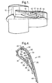
- FIG. 4 of the accompanying drawings shows a transverse section through a hollow wall-cooled nozzle guide vane, generally indicated at 20.
- the wall cooling cavities are indicated at 22,24,26 on the convex side of the vane and at 28 on the opposite side. Generally speaking these cavities are formed within the walls 30,32 of the aerofoil section of the vane 20.
- the interior space of the vane is formed as two hollow core cavities 34,36 separated by a dividing wall 38 which extend substantially the full height of the vane between its inner and outer platforms (not shown). Cooling air entry apertures which communicate with a source of cooling air are provided to admit the air into the interior cavity 34.
- cooling air simply passing through the wall cavities 22-28 absorbs heat from the vane walls 30,32. The amount of heat thus extracted is increased by arranging for the air to enter the cavities as impingement cooling jets.
- the vane is effectively double-walled so that there is an inner wall 30a spaced from outer wall 30 and an inner wall 32a spaced from outer wall 32. Between these inner and outer walls lie the wall cooling cavities 22-28.
- a multiplicity of impingement holes, such as indicated at 40 pierce the inner wall so that air flowing into the wall cavities as a result of a pressure differential is caused to impinge upon the inner surface of the outer walls.
- This cooling air may exit the cavities in several ways.
- wall cavity 22 the air is exhausted through film holes 42 in the outer wall to generate an outer surface cooling film.
- wall cavity 24 the cooling air is ducted through the cavity around dividing wall 38 to feed core cavity 36.
- the preferred method of manufacturing such a vane is by an investment casting process in which a solid model of the interconnected cooling cavities is created. This model is then built into a wax model of the solid parts of the vane walls and then "invested” with ceramic slurry. When the slurry has hardened and has been fired the wax melts and is lost leaving the complex "cooling" core inside a ceramic shell.
- a core is shown in Figure 5. What appears in this drawing to be solid chambers represent the hollow cooling chambers in a finished, cast vane and are referenced as such. Thus it will be seen in this particular embodiment the cavities 22,24,26 (and 28 although hidden from view) are divided into a stack of thirteen smaller, parallel cavities labelled 22a-22m. In the cast vane the cooling cavities exactly mirror the shape of this core.
- FIG. 6 An alternative embodiment of the core for the convex side of component 20 is shown in Figure 6.
- the cavities 22 and 24 are divided into a stack of thirteen cells labelled 22a-22m and 24a-24m respectively, whereas cavity 26 is divided into a stack of twelve parallel cells 26b-26m.
- the side wall cavities 22, 24 and 26 could be arranged so that none are divided into the same number of cells.
- the cooling requirement of the component 20 is the main factor in determining the number, spacing and geometry of the sub-divided cells within cavities 22 - 26.
Landscapes
- Engineering & Computer Science (AREA)
- Mechanical Engineering (AREA)
- General Engineering & Computer Science (AREA)
- Turbine Rotor Nozzle Sealing (AREA)
- Thermotherapy And Cooling Therapy Devices (AREA)
Abstract
Description
Claims (4)
- An air cooled component (20) provided with an internal air cooling system comprising an internal cavity (34)(36) and at least one side wall chamber (22-28) formed in the wall (30)(32) of the component (20), having at least one air entry aperture (40) for admitting cooling air into the side wall chamber (22-28) and at least one air exit aperture (40-46) for exhausting air from the side wall chamber (22-28), and the internal cavity (34)(36) is divided into at least two compartments (34)(36) which are arranged in flow sequence by communication through the side wall chambers (24)(28), characterised in that at least one of the side wall chambers (22-28) is sub-divided into a plurality of cells (22a-26m) in parallel flow relationship and each of the cells (22a-26m) has at least one air entry aperture (40) and at least one air exit aperture (40-46).
- An air cooled component (20) as claimed in claim 1 characterised in that there are a plurality of such cooling chambers (22-28) formed in the wall (30)(32) of the component (20) and each chamber (22-28) is sub-divided into a plurality of parallel cells (22a-26m).
- An air cooled component (20) as claimed in claim 1 or claim 2 characterised in that the component (20) is formed with an internal cavity (34)(36) extending the length of the component (20), which cavity in use is supplied with cooling air, and the air entry apertures (40) communicate with said cavity to receive cooling air.
- An air cooled component (20) as claimed in claim 1, claim 2 or claim 3 characterised in that the component (20) is formed with an internal cavity (34)(36) that exhausts air from an aperture (44) located towards the trailing edge of the component (20).
Applications Claiming Priority (2)
| Application Number | Priority Date | Filing Date | Title |
|---|---|---|---|
| GB0114503 | 2001-06-14 | ||
| GBGB0114503.6A GB0114503D0 (en) | 2001-06-14 | 2001-06-14 | Air cooled aerofoil |
Publications (3)
| Publication Number | Publication Date |
|---|---|
| EP1267038A2 true EP1267038A2 (en) | 2002-12-18 |
| EP1267038A3 EP1267038A3 (en) | 2005-01-05 |
| EP1267038B1 EP1267038B1 (en) | 2006-05-03 |
Family
ID=9916577
Family Applications (1)
| Application Number | Title | Priority Date | Filing Date |
|---|---|---|---|
| EP02253514A Expired - Lifetime EP1267038B1 (en) | 2001-06-14 | 2002-05-20 | Air cooled aerofoil |
Country Status (4)
| Country | Link |
|---|---|
| US (1) | US6773230B2 (en) |
| EP (1) | EP1267038B1 (en) |
| DE (1) | DE60211066T2 (en) |
| GB (2) | GB0114503D0 (en) |
Cited By (15)
| Publication number | Priority date | Publication date | Assignee | Title |
|---|---|---|---|---|
| EP1505256A2 (en) | 2003-08-08 | 2005-02-09 | United Technologies Corporation | Microcircuit cooling for a turbine blade |
| US7153096B2 (en) | 2004-12-02 | 2006-12-26 | Siemens Power Generation, Inc. | Stacked laminate CMC turbine vane |
| US7198458B2 (en) | 2004-12-02 | 2007-04-03 | Siemens Power Generation, Inc. | Fail safe cooling system for turbine vanes |
| US7255535B2 (en) | 2004-12-02 | 2007-08-14 | Albrecht Harry A | Cooling systems for stacked laminate CMC vane |
| US7281784B2 (en) | 2003-02-10 | 2007-10-16 | Sony Corporation | Liquid discharge apparatus and method for discharging liquid |
| EP1881157A1 (en) | 2006-07-18 | 2008-01-23 | United Technologies Corporation | Serpentine microcircuits for local heat removal |
| JP2008032008A (en) * | 2006-07-28 | 2008-02-14 | United Technol Corp <Utc> | Serpentine microcircuit for transferring high temperature gas |
| EP1593812A3 (en) * | 2004-05-06 | 2009-05-13 | United Technologies Corporation | Cooled turbine airfoil |
| WO2009148655A3 (en) * | 2008-05-29 | 2010-08-26 | General Electric Company | Turbine airfoil with metered cooling cavity |
| EP1998004A3 (en) * | 2007-03-06 | 2011-09-21 | United Technologies Corporation | Turbine component with axially spaced radially flowing microcircuit cooling channels |
| EP2136034A3 (en) * | 2008-06-17 | 2013-04-03 | Rolls-Royce plc | A cooling arrangement |
| WO2014078305A1 (en) * | 2012-11-13 | 2014-05-22 | Siemens Energy, Inc. | Process for forming a long gas turbine engine blade having a main wall with a thin portion near a tip |
| JP2015527530A (en) * | 2012-08-20 | 2015-09-17 | アルストム テクノロジー リミテッドALSTOM Technology Ltd | Internally cooled wings for rotating machinery |
| EP2943655A4 (en) * | 2013-01-09 | 2016-06-01 | United Technologies Corp | AERODYNAMIC PROFILE AND METHOD OF MANUFACTURE |
| CN110030036A (en) * | 2019-05-10 | 2019-07-19 | 沈阳航空航天大学 | Seam gaseous film control structure is split in a kind of impact of turbine blade tail |
Families Citing this family (35)
| Publication number | Priority date | Publication date | Assignee | Title |
|---|---|---|---|---|
| FR2858352B1 (en) * | 2003-08-01 | 2006-01-20 | Snecma Moteurs | COOLING CIRCUIT FOR TURBINE BLADE |
| US7172012B1 (en) * | 2004-07-14 | 2007-02-06 | United Technologies Corporation | Investment casting |
| US7217088B2 (en) * | 2005-02-02 | 2007-05-15 | Siemens Power Generation, Inc. | Cooling fluid preheating system for an airfoil in a turbine engine |
| US7303376B2 (en) * | 2005-12-02 | 2007-12-04 | Siemens Power Generation, Inc. | Turbine airfoil with outer wall cooling system and inner mid-chord hot gas receiving cavity |
| US7780413B2 (en) * | 2006-08-01 | 2010-08-24 | Siemens Energy, Inc. | Turbine airfoil with near wall inflow chambers |
| US7625179B2 (en) * | 2006-09-13 | 2009-12-01 | United Technologies Corporation | Airfoil thermal management with microcircuit cooling |
| US8197184B2 (en) * | 2006-10-18 | 2012-06-12 | United Technologies Corporation | Vane with enhanced heat transfer |
| US7556476B1 (en) | 2006-11-16 | 2009-07-07 | Florida Turbine Technologies, Inc. | Turbine airfoil with multiple near wall compartment cooling |
| US8757974B2 (en) * | 2007-01-11 | 2014-06-24 | United Technologies Corporation | Cooling circuit flow path for a turbine section airfoil |
| US7845906B2 (en) * | 2007-01-24 | 2010-12-07 | United Technologies Corporation | Dual cut-back trailing edge for airfoils |
| US7837441B2 (en) * | 2007-02-16 | 2010-11-23 | United Technologies Corporation | Impingement skin core cooling for gas turbine engine blade |
| US7836703B2 (en) * | 2007-06-20 | 2010-11-23 | General Electric Company | Reciprocal cooled turbine nozzle |
| US8016546B2 (en) * | 2007-07-24 | 2011-09-13 | United Technologies Corp. | Systems and methods for providing vane platform cooling |
| US8047789B1 (en) * | 2007-10-19 | 2011-11-01 | Florida Turbine Technologies, Inc. | Turbine airfoil |
| US8105033B2 (en) * | 2008-06-05 | 2012-01-31 | United Technologies Corporation | Particle resistant in-wall cooling passage inlet |
| US8439628B2 (en) * | 2010-01-06 | 2013-05-14 | General Electric Company | Heat transfer enhancement in internal cavities of turbine engine airfoils |
| US9296039B2 (en) | 2012-04-24 | 2016-03-29 | United Technologies Corporation | Gas turbine engine airfoil impingement cooling |
| US9115590B2 (en) * | 2012-09-26 | 2015-08-25 | United Technologies Corporation | Gas turbine engine airfoil cooling circuit |
| WO2015009448A1 (en) * | 2013-07-19 | 2015-01-22 | United Technologies Corporation | Additively manufactured core |
| EP2886798B1 (en) | 2013-12-20 | 2018-10-24 | Rolls-Royce Corporation | mechanically machined film cooling holes |
| FR3034128B1 (en) * | 2015-03-23 | 2017-04-14 | Snecma | CERAMIC CORE FOR MULTI-CAVITY TURBINE BLADE |
| US10323524B2 (en) | 2015-05-08 | 2019-06-18 | United Technologies Corporation | Axial skin core cooling passage for a turbine engine component |
| US10502066B2 (en) | 2015-05-08 | 2019-12-10 | United Technologies Corporation | Turbine engine component including an axially aligned skin core passage interrupted by a pedestal |
| CA2935398A1 (en) * | 2015-07-31 | 2017-01-31 | Rolls-Royce Corporation | Turbine airfoils with micro cooling features |
| US10364681B2 (en) | 2015-10-15 | 2019-07-30 | General Electric Company | Turbine blade |
| US10024171B2 (en) | 2015-12-09 | 2018-07-17 | General Electric Company | Article and method of cooling an article |
| US10465526B2 (en) | 2016-11-15 | 2019-11-05 | Rolls-Royce Corporation | Dual-wall airfoil with leading edge cooling slot |
| FR3067390B1 (en) * | 2017-04-10 | 2019-11-29 | Safran | TURBINE DAWN WITH AN IMPROVED STRUCTURE |
| US10450873B2 (en) * | 2017-07-31 | 2019-10-22 | Rolls-Royce Corporation | Airfoil edge cooling channels |
| US11480057B2 (en) * | 2017-10-24 | 2022-10-25 | Raytheon Technologies Corporation | Airfoil cooling circuit |
| US10753210B2 (en) * | 2018-05-02 | 2020-08-25 | Raytheon Technologies Corporation | Airfoil having improved cooling scheme |
| US11753944B2 (en) | 2018-11-09 | 2023-09-12 | Raytheon Technologies Corporation | Airfoil with wall that tapers in thickness |
| US12385433B2 (en) | 2023-05-30 | 2025-08-12 | Doosan Enerbility Co., Ltd. | Gas turbine plant with ammonia decomposition system |
| CN116988918A (en) * | 2023-08-07 | 2023-11-03 | 上海理工大学 | Anti-icing/de-icing wind turbine blades with double-wall construction |
| JP7764682B2 (en) * | 2023-12-26 | 2025-11-06 | ドゥサン エナービリティー カンパニー リミテッド | Airfoil and gas turbine including same |
Family Cites Families (17)
| Publication number | Priority date | Publication date | Assignee | Title |
|---|---|---|---|---|
| GB1175816A (en) * | 1968-06-24 | 1969-12-23 | Rolls Royce | Improvements relating to the Cooling of Aerofoil Shaped Blades |
| US3672787A (en) * | 1969-10-31 | 1972-06-27 | Avco Corp | Turbine blade having a cooled laminated skin |
| US3698834A (en) * | 1969-11-24 | 1972-10-17 | Gen Motors Corp | Transpiration cooling |
| GB1285369A (en) * | 1969-12-16 | 1972-08-16 | Rolls Royce | Improvements in or relating to blades for fluid flow machines |
| CH584347A5 (en) * | 1974-11-08 | 1977-01-31 | Bbc Sulzer Turbomaschinen | |
| US4768700A (en) * | 1987-08-17 | 1988-09-06 | General Motors Corporation | Diffusion bonding method |
| JP2862536B2 (en) * | 1987-09-25 | 1999-03-03 | 株式会社東芝 | Gas turbine blades |
| US5720431A (en) * | 1988-08-24 | 1998-02-24 | United Technologies Corporation | Cooled blades for a gas turbine engine |
| US5383766A (en) * | 1990-07-09 | 1995-01-24 | United Technologies Corporation | Cooled vane |
| FR2689176B1 (en) * | 1992-03-25 | 1995-07-13 | Snecma | DAWN REFRIGERATED FROM TURBO-MACHINE. |
| JP3651490B2 (en) * | 1993-12-28 | 2005-05-25 | 株式会社東芝 | Turbine cooling blade |
| EP0973998B1 (en) * | 1997-04-07 | 2001-09-19 | Siemens Aktiengesellschaft | Method for cooling a turbine blade |
| US6099252A (en) * | 1998-11-16 | 2000-08-08 | General Electric Company | Axial serpentine cooled airfoil |
| US6213714B1 (en) * | 1999-06-29 | 2001-04-10 | Allison Advanced Development Company | Cooled airfoil |
| US6402470B1 (en) * | 1999-10-05 | 2002-06-11 | United Technologies Corporation | Method and apparatus for cooling a wall within a gas turbine engine |
| US6254334B1 (en) * | 1999-10-05 | 2001-07-03 | United Technologies Corporation | Method and apparatus for cooling a wall within a gas turbine engine |
| US6511293B2 (en) * | 2001-05-29 | 2003-01-28 | Siemens Westinghouse Power Corporation | Closed loop steam cooled airfoil |
-
2001
- 2001-06-14 GB GBGB0114503.6A patent/GB0114503D0/en not_active Ceased
-
2002
- 2002-04-23 GB GB0209231A patent/GB2377732B/en not_active Revoked
- 2002-05-20 DE DE60211066T patent/DE60211066T2/en not_active Expired - Lifetime
- 2002-05-20 EP EP02253514A patent/EP1267038B1/en not_active Expired - Lifetime
- 2002-05-29 US US10/156,075 patent/US6773230B2/en not_active Expired - Lifetime
Cited By (20)
| Publication number | Priority date | Publication date | Assignee | Title |
|---|---|---|---|---|
| US7281784B2 (en) | 2003-02-10 | 2007-10-16 | Sony Corporation | Liquid discharge apparatus and method for discharging liquid |
| EP1505256A3 (en) * | 2003-08-08 | 2008-06-25 | United Technologies Corporation | Microcircuit cooling for a turbine blade |
| EP1505256A2 (en) | 2003-08-08 | 2005-02-09 | United Technologies Corporation | Microcircuit cooling for a turbine blade |
| EP1593812A3 (en) * | 2004-05-06 | 2009-05-13 | United Technologies Corporation | Cooled turbine airfoil |
| US7153096B2 (en) | 2004-12-02 | 2006-12-26 | Siemens Power Generation, Inc. | Stacked laminate CMC turbine vane |
| US7198458B2 (en) | 2004-12-02 | 2007-04-03 | Siemens Power Generation, Inc. | Fail safe cooling system for turbine vanes |
| US7255535B2 (en) | 2004-12-02 | 2007-08-14 | Albrecht Harry A | Cooling systems for stacked laminate CMC vane |
| EP1881157A1 (en) | 2006-07-18 | 2008-01-23 | United Technologies Corporation | Serpentine microcircuits for local heat removal |
| JP2008032008A (en) * | 2006-07-28 | 2008-02-14 | United Technol Corp <Utc> | Serpentine microcircuit for transferring high temperature gas |
| US7581928B1 (en) | 2006-07-28 | 2009-09-01 | United Technologies Corporation | Serpentine microcircuits for hot gas migration |
| EP1998004A3 (en) * | 2007-03-06 | 2011-09-21 | United Technologies Corporation | Turbine component with axially spaced radially flowing microcircuit cooling channels |
| WO2009148655A3 (en) * | 2008-05-29 | 2010-08-26 | General Electric Company | Turbine airfoil with metered cooling cavity |
| GB2472548A (en) * | 2008-05-29 | 2011-02-09 | Gen Electric | Turbine airfoil with metered cooling cavity |
| GB2472548B (en) * | 2008-05-29 | 2013-02-20 | Gen Electric | Turbine airfoil with metered cooling cavity |
| EP2136034A3 (en) * | 2008-06-17 | 2013-04-03 | Rolls-Royce plc | A cooling arrangement |
| JP2015527530A (en) * | 2012-08-20 | 2015-09-17 | アルストム テクノロジー リミテッドALSTOM Technology Ltd | Internally cooled wings for rotating machinery |
| WO2014078305A1 (en) * | 2012-11-13 | 2014-05-22 | Siemens Energy, Inc. | Process for forming a long gas turbine engine blade having a main wall with a thin portion near a tip |
| EP2943655A4 (en) * | 2013-01-09 | 2016-06-01 | United Technologies Corp | AERODYNAMIC PROFILE AND METHOD OF MANUFACTURE |
| US9551228B2 (en) | 2013-01-09 | 2017-01-24 | United Technologies Corporation | Airfoil and method of making |
| CN110030036A (en) * | 2019-05-10 | 2019-07-19 | 沈阳航空航天大学 | Seam gaseous film control structure is split in a kind of impact of turbine blade tail |
Also Published As
| Publication number | Publication date |
|---|---|
| DE60211066T2 (en) | 2006-11-02 |
| GB0114503D0 (en) | 2001-08-08 |
| US20030059305A1 (en) | 2003-03-27 |
| GB2377732A (en) | 2003-01-22 |
| GB0209231D0 (en) | 2002-06-05 |
| EP1267038B1 (en) | 2006-05-03 |
| US6773230B2 (en) | 2004-08-10 |
| GB2377732B (en) | 2004-04-07 |
| DE60211066D1 (en) | 2006-06-08 |
| EP1267038A3 (en) | 2005-01-05 |
Similar Documents
| Publication | Publication Date | Title |
|---|---|---|
| EP1267038B1 (en) | Air cooled aerofoil | |
| EP2855857B1 (en) | Blade outer air seal with cored passages | |
| KR100573658B1 (en) | Turbine elements | |
| US7625180B1 (en) | Turbine blade with near-wall multi-metering and diffusion cooling circuit | |
| EP0791127B1 (en) | Gas turbine vane with a cooled inner shroud | |
| EP1921272B1 (en) | Air-cooled aerofoil for a gas turbine engine | |
| EP2388437B2 (en) | Cooling circuit flow path for a turbine section airfoil | |
| US6422817B1 (en) | Cooling circuit for and method of cooling a gas turbine bucket | |
| US7377746B2 (en) | Airfoil cooling circuits and method | |
| EP1445424B1 (en) | Hollow airfoil provided with an embedded microcircuit for tip cooling | |
| US6506013B1 (en) | Film cooling for a closed loop cooled airfoil | |
| US7217095B2 (en) | Heat transferring cooling features for an airfoil | |
| US8047790B1 (en) | Near wall compartment cooled turbine blade | |
| EP1088964A2 (en) | Slotted impingement cooling of airfoil leading edge | |
| US9033652B2 (en) | Method and apparatus for cooling gas turbine rotor blades | |
| CA2462986A1 (en) | Method and apparatus for cooling an airfoil | |
| EP3216982A1 (en) | Turbine airfoil having near-wall cooling insert | |
| GB2301405A (en) | Gas turbine guide nozzle vane | |
| EP3976930B1 (en) | Turbine blade with serpentine channels | |
| KR102764478B1 (en) | Airfoil with internal crossover passages and pin array | |
| CA2205042C (en) | Gas turbine vane with a cooled inner shroud |
Legal Events
| Date | Code | Title | Description |
|---|---|---|---|
| PUAI | Public reference made under article 153(3) epc to a published international application that has entered the european phase |
Free format text: ORIGINAL CODE: 0009012 |
|
| AK | Designated contracting states |
Kind code of ref document: A2 Designated state(s): AT BE CH CY DE DK ES FI FR GB GR IE IT LI LU MC NL PT SE TR |
|
| AX | Request for extension of the european patent |
Free format text: AL;LT;LV;MK;RO;SI |
|
| PUAL | Search report despatched |
Free format text: ORIGINAL CODE: 0009013 |
|
| AK | Designated contracting states |
Kind code of ref document: A3 Designated state(s): AT BE CH CY DE DK ES FI FR GB GR IE IT LI LU MC NL PT SE TR |
|
| AX | Request for extension of the european patent |
Extension state: AL LT LV MK RO SI |
|
| 17P | Request for examination filed |
Effective date: 20050120 |
|
| 17Q | First examination report despatched |
Effective date: 20050408 |
|
| AKX | Designation fees paid |
Designated state(s): DE FR GB |
|
| GRAP | Despatch of communication of intention to grant a patent |
Free format text: ORIGINAL CODE: EPIDOSNIGR1 |
|
| GRAS | Grant fee paid |
Free format text: ORIGINAL CODE: EPIDOSNIGR3 |
|
| GRAA | (expected) grant |
Free format text: ORIGINAL CODE: 0009210 |
|
| AK | Designated contracting states |
Kind code of ref document: B1 Designated state(s): DE FR GB |
|
| REG | Reference to a national code |
Ref country code: GB Ref legal event code: FG4D |
|
| REF | Corresponds to: |
Ref document number: 60211066 Country of ref document: DE Date of ref document: 20060608 Kind code of ref document: P |
|
| ET | Fr: translation filed | ||
| PLBE | No opposition filed within time limit |
Free format text: ORIGINAL CODE: 0009261 |
|
| STAA | Information on the status of an ep patent application or granted ep patent |
Free format text: STATUS: NO OPPOSITION FILED WITHIN TIME LIMIT |
|
| 26N | No opposition filed |
Effective date: 20070206 |
|
| REG | Reference to a national code |
Ref country code: FR Ref legal event code: PLFP Year of fee payment: 14 |
|
| PGFP | Annual fee paid to national office [announced via postgrant information from national office to epo] |
Ref country code: DE Payment date: 20150528 Year of fee payment: 14 Ref country code: GB Payment date: 20150527 Year of fee payment: 14 |
|
| PGFP | Annual fee paid to national office [announced via postgrant information from national office to epo] |
Ref country code: FR Payment date: 20150519 Year of fee payment: 14 |
|
| REG | Reference to a national code |
Ref country code: DE Ref legal event code: R119 Ref document number: 60211066 Country of ref document: DE |
|
| GBPC | Gb: european patent ceased through non-payment of renewal fee |
Effective date: 20160520 |
|
| REG | Reference to a national code |
Ref country code: FR Ref legal event code: ST Effective date: 20170131 |
|
| PG25 | Lapsed in a contracting state [announced via postgrant information from national office to epo] |
Ref country code: FR Free format text: LAPSE BECAUSE OF NON-PAYMENT OF DUE FEES Effective date: 20160531 Ref country code: DE Free format text: LAPSE BECAUSE OF NON-PAYMENT OF DUE FEES Effective date: 20161201 |
|
| PG25 | Lapsed in a contracting state [announced via postgrant information from national office to epo] |
Ref country code: GB Free format text: LAPSE BECAUSE OF NON-PAYMENT OF DUE FEES Effective date: 20160520 |
|
| REG | Reference to a national code |
Ref country code: FR Ref legal event code: CA Effective date: 20170517 |