EP1266936A1 - Epoxy resin composition used for encapsulating semiconductor and semiconductor device using the composition - Google Patents
Epoxy resin composition used for encapsulating semiconductor and semiconductor device using the composition Download PDFInfo
- Publication number
- EP1266936A1 EP1266936A1 EP02013407A EP02013407A EP1266936A1 EP 1266936 A1 EP1266936 A1 EP 1266936A1 EP 02013407 A EP02013407 A EP 02013407A EP 02013407 A EP02013407 A EP 02013407A EP 1266936 A1 EP1266936 A1 EP 1266936A1
- Authority
- EP
- European Patent Office
- Prior art keywords
- epoxy resin
- resin composition
- encapsulating
- composition according
- resin layer
- Prior art date
- Legal status (The legal status is an assumption and is not a legal conclusion. Google has not performed a legal analysis and makes no representation as to the accuracy of the status listed.)
- Granted
Links
Images

Classifications
-
- C—CHEMISTRY; METALLURGY
- C08—ORGANIC MACROMOLECULAR COMPOUNDS; THEIR PREPARATION OR CHEMICAL WORKING-UP; COMPOSITIONS BASED THEREON
- C08G—MACROMOLECULAR COMPOUNDS OBTAINED OTHERWISE THAN BY REACTIONS ONLY INVOLVING UNSATURATED CARBON-TO-CARBON BONDS
- C08G59/00—Polycondensates containing more than one epoxy group per molecule; Macromolecules obtained by polymerising compounds containing more than one epoxy group per molecule using curing agents or catalysts which react with the epoxy groups
- C08G59/18—Macromolecules obtained by polymerising compounds containing more than one epoxy group per molecule using curing agents or catalysts which react with the epoxy groups ; e.g. general methods of curing
- C08G59/40—Macromolecules obtained by polymerising compounds containing more than one epoxy group per molecule using curing agents or catalysts which react with the epoxy groups ; e.g. general methods of curing characterised by the curing agents used
- C08G59/62—Alcohols or phenols
- C08G59/621—Phenols
-
- C—CHEMISTRY; METALLURGY
- C08—ORGANIC MACROMOLECULAR COMPOUNDS; THEIR PREPARATION OR CHEMICAL WORKING-UP; COMPOSITIONS BASED THEREON
- C08G—MACROMOLECULAR COMPOUNDS OBTAINED OTHERWISE THAN BY REACTIONS ONLY INVOLVING UNSATURATED CARBON-TO-CARBON BONDS
- C08G59/00—Polycondensates containing more than one epoxy group per molecule; Macromolecules obtained by polymerising compounds containing more than one epoxy group per molecule using curing agents or catalysts which react with the epoxy groups
- C08G59/02—Polycondensates containing more than one epoxy group per molecule
- C08G59/04—Polycondensates containing more than one epoxy group per molecule of polyhydroxy compounds with epihalohydrins or precursors thereof
- C08G59/06—Polycondensates containing more than one epoxy group per molecule of polyhydroxy compounds with epihalohydrins or precursors thereof of polyhydric phenols
- C08G59/08—Polycondensates containing more than one epoxy group per molecule of polyhydroxy compounds with epihalohydrins or precursors thereof of polyhydric phenols from phenol-aldehyde condensates
-
- H—ELECTRICITY
- H01—ELECTRIC ELEMENTS
- H01L—SEMICONDUCTOR DEVICES NOT COVERED BY CLASS H10
- H01L23/00—Details of semiconductor or other solid state devices
- H01L23/28—Encapsulations, e.g. encapsulating layers, coatings, e.g. for protection
- H01L23/31—Encapsulations, e.g. encapsulating layers, coatings, e.g. for protection characterised by the arrangement or shape
- H01L23/3107—Encapsulations, e.g. encapsulating layers, coatings, e.g. for protection characterised by the arrangement or shape the device being completely enclosed
- H01L23/3135—Double encapsulation or coating and encapsulation
-
- H—ELECTRICITY
- H01—ELECTRIC ELEMENTS
- H01L—SEMICONDUCTOR DEVICES NOT COVERED BY CLASS H10
- H01L23/00—Details of semiconductor or other solid state devices
- H01L23/552—Protection against radiation, e.g. light or electromagnetic waves
-
- H—ELECTRICITY
- H01—ELECTRIC ELEMENTS
- H01L—SEMICONDUCTOR DEVICES NOT COVERED BY CLASS H10
- H01L2224/00—Indexing scheme for arrangements for connecting or disconnecting semiconductor or solid-state bodies and methods related thereto as covered by H01L24/00
- H01L2224/01—Means for bonding being attached to, or being formed on, the surface to be connected, e.g. chip-to-package, die-attach, "first-level" interconnects; Manufacturing methods related thereto
- H01L2224/42—Wire connectors; Manufacturing methods related thereto
- H01L2224/44—Structure, shape, material or disposition of the wire connectors prior to the connecting process
- H01L2224/45—Structure, shape, material or disposition of the wire connectors prior to the connecting process of an individual wire connector
- H01L2224/45001—Core members of the connector
- H01L2224/45099—Material
- H01L2224/451—Material with a principal constituent of the material being a metal or a metalloid, e.g. boron (B), silicon (Si), germanium (Ge), arsenic (As), antimony (Sb), tellurium (Te) and polonium (Po), and alloys thereof
- H01L2224/45138—Material with a principal constituent of the material being a metal or a metalloid, e.g. boron (B), silicon (Si), germanium (Ge), arsenic (As), antimony (Sb), tellurium (Te) and polonium (Po), and alloys thereof the principal constituent melting at a temperature of greater than or equal to 950°C and less than 1550°C
- H01L2224/45144—Gold (Au) as principal constituent
-
- H—ELECTRICITY
- H01—ELECTRIC ELEMENTS
- H01L—SEMICONDUCTOR DEVICES NOT COVERED BY CLASS H10
- H01L2224/00—Indexing scheme for arrangements for connecting or disconnecting semiconductor or solid-state bodies and methods related thereto as covered by H01L24/00
- H01L2224/01—Means for bonding being attached to, or being formed on, the surface to be connected, e.g. chip-to-package, die-attach, "first-level" interconnects; Manufacturing methods related thereto
- H01L2224/42—Wire connectors; Manufacturing methods related thereto
- H01L2224/47—Structure, shape, material or disposition of the wire connectors after the connecting process
- H01L2224/48—Structure, shape, material or disposition of the wire connectors after the connecting process of an individual wire connector
- H01L2224/4805—Shape
- H01L2224/4809—Loop shape
- H01L2224/48091—Arched
-
- H—ELECTRICITY
- H01—ELECTRIC ELEMENTS
- H01L—SEMICONDUCTOR DEVICES NOT COVERED BY CLASS H10
- H01L2224/00—Indexing scheme for arrangements for connecting or disconnecting semiconductor or solid-state bodies and methods related thereto as covered by H01L24/00
- H01L2224/01—Means for bonding being attached to, or being formed on, the surface to be connected, e.g. chip-to-package, die-attach, "first-level" interconnects; Manufacturing methods related thereto
- H01L2224/42—Wire connectors; Manufacturing methods related thereto
- H01L2224/47—Structure, shape, material or disposition of the wire connectors after the connecting process
- H01L2224/48—Structure, shape, material or disposition of the wire connectors after the connecting process of an individual wire connector
- H01L2224/481—Disposition
- H01L2224/48151—Connecting between a semiconductor or solid-state body and an item not being a semiconductor or solid-state body, e.g. chip-to-substrate, chip-to-passive
- H01L2224/48221—Connecting between a semiconductor or solid-state body and an item not being a semiconductor or solid-state body, e.g. chip-to-substrate, chip-to-passive the body and the item being stacked
- H01L2224/48225—Connecting between a semiconductor or solid-state body and an item not being a semiconductor or solid-state body, e.g. chip-to-substrate, chip-to-passive the body and the item being stacked the item being non-metallic, e.g. insulating substrate with or without metallisation
- H01L2224/48227—Connecting between a semiconductor or solid-state body and an item not being a semiconductor or solid-state body, e.g. chip-to-substrate, chip-to-passive the body and the item being stacked the item being non-metallic, e.g. insulating substrate with or without metallisation connecting the wire to a bond pad of the item
-
- H—ELECTRICITY
- H01—ELECTRIC ELEMENTS
- H01L—SEMICONDUCTOR DEVICES NOT COVERED BY CLASS H10
- H01L2224/00—Indexing scheme for arrangements for connecting or disconnecting semiconductor or solid-state bodies and methods related thereto as covered by H01L24/00
- H01L2224/01—Means for bonding being attached to, or being formed on, the surface to be connected, e.g. chip-to-package, die-attach, "first-level" interconnects; Manufacturing methods related thereto
- H01L2224/42—Wire connectors; Manufacturing methods related thereto
- H01L2224/47—Structure, shape, material or disposition of the wire connectors after the connecting process
- H01L2224/48—Structure, shape, material or disposition of the wire connectors after the connecting process of an individual wire connector
- H01L2224/481—Disposition
- H01L2224/48151—Connecting between a semiconductor or solid-state body and an item not being a semiconductor or solid-state body, e.g. chip-to-substrate, chip-to-passive
- H01L2224/48221—Connecting between a semiconductor or solid-state body and an item not being a semiconductor or solid-state body, e.g. chip-to-substrate, chip-to-passive the body and the item being stacked
- H01L2224/48245—Connecting between a semiconductor or solid-state body and an item not being a semiconductor or solid-state body, e.g. chip-to-substrate, chip-to-passive the body and the item being stacked the item being metallic
- H01L2224/48247—Connecting between a semiconductor or solid-state body and an item not being a semiconductor or solid-state body, e.g. chip-to-substrate, chip-to-passive the body and the item being stacked the item being metallic connecting the wire to a bond pad of the item
-
- H—ELECTRICITY
- H01—ELECTRIC ELEMENTS
- H01L—SEMICONDUCTOR DEVICES NOT COVERED BY CLASS H10
- H01L24/00—Arrangements for connecting or disconnecting semiconductor or solid-state bodies; Methods or apparatus related thereto
- H01L24/01—Means for bonding being attached to, or being formed on, the surface to be connected, e.g. chip-to-package, die-attach, "first-level" interconnects; Manufacturing methods related thereto
- H01L24/42—Wire connectors; Manufacturing methods related thereto
- H01L24/44—Structure, shape, material or disposition of the wire connectors prior to the connecting process
- H01L24/45—Structure, shape, material or disposition of the wire connectors prior to the connecting process of an individual wire connector
-
- H—ELECTRICITY
- H01—ELECTRIC ELEMENTS
- H01L—SEMICONDUCTOR DEVICES NOT COVERED BY CLASS H10
- H01L24/00—Arrangements for connecting or disconnecting semiconductor or solid-state bodies; Methods or apparatus related thereto
- H01L24/01—Means for bonding being attached to, or being formed on, the surface to be connected, e.g. chip-to-package, die-attach, "first-level" interconnects; Manufacturing methods related thereto
- H01L24/42—Wire connectors; Manufacturing methods related thereto
- H01L24/47—Structure, shape, material or disposition of the wire connectors after the connecting process
- H01L24/48—Structure, shape, material or disposition of the wire connectors after the connecting process of an individual wire connector
-
- H—ELECTRICITY
- H01—ELECTRIC ELEMENTS
- H01L—SEMICONDUCTOR DEVICES NOT COVERED BY CLASS H10
- H01L2924/00—Indexing scheme for arrangements or methods for connecting or disconnecting semiconductor or solid-state bodies as covered by H01L24/00
- H01L2924/0001—Technical content checked by a classifier
- H01L2924/00014—Technical content checked by a classifier the subject-matter covered by the group, the symbol of which is combined with the symbol of this group, being disclosed without further technical details
-
- H—ELECTRICITY
- H01—ELECTRIC ELEMENTS
- H01L—SEMICONDUCTOR DEVICES NOT COVERED BY CLASS H10
- H01L2924/00—Indexing scheme for arrangements or methods for connecting or disconnecting semiconductor or solid-state bodies as covered by H01L24/00
- H01L2924/01—Chemical elements
- H01L2924/01012—Magnesium [Mg]
-
- H—ELECTRICITY
- H01—ELECTRIC ELEMENTS
- H01L—SEMICONDUCTOR DEVICES NOT COVERED BY CLASS H10
- H01L2924/00—Indexing scheme for arrangements or methods for connecting or disconnecting semiconductor or solid-state bodies as covered by H01L24/00
- H01L2924/01—Chemical elements
- H01L2924/01019—Potassium [K]
-
- H—ELECTRICITY
- H01—ELECTRIC ELEMENTS
- H01L—SEMICONDUCTOR DEVICES NOT COVERED BY CLASS H10
- H01L2924/00—Indexing scheme for arrangements or methods for connecting or disconnecting semiconductor or solid-state bodies as covered by H01L24/00
- H01L2924/01—Chemical elements
- H01L2924/0102—Calcium [Ca]
-
- H—ELECTRICITY
- H01—ELECTRIC ELEMENTS
- H01L—SEMICONDUCTOR DEVICES NOT COVERED BY CLASS H10
- H01L2924/00—Indexing scheme for arrangements or methods for connecting or disconnecting semiconductor or solid-state bodies as covered by H01L24/00
- H01L2924/01—Chemical elements
- H01L2924/01025—Manganese [Mn]
-
- H—ELECTRICITY
- H01—ELECTRIC ELEMENTS
- H01L—SEMICONDUCTOR DEVICES NOT COVERED BY CLASS H10
- H01L2924/00—Indexing scheme for arrangements or methods for connecting or disconnecting semiconductor or solid-state bodies as covered by H01L24/00
- H01L2924/01—Chemical elements
- H01L2924/01079—Gold [Au]
-
- H—ELECTRICITY
- H01—ELECTRIC ELEMENTS
- H01L—SEMICONDUCTOR DEVICES NOT COVERED BY CLASS H10
- H01L2924/00—Indexing scheme for arrangements or methods for connecting or disconnecting semiconductor or solid-state bodies as covered by H01L24/00
- H01L2924/01—Chemical elements
- H01L2924/01087—Francium [Fr]
-
- H—ELECTRICITY
- H01—ELECTRIC ELEMENTS
- H01L—SEMICONDUCTOR DEVICES NOT COVERED BY CLASS H10
- H01L2924/00—Indexing scheme for arrangements or methods for connecting or disconnecting semiconductor or solid-state bodies as covered by H01L24/00
- H01L2924/10—Details of semiconductor or other solid state devices to be connected
- H01L2924/11—Device type
- H01L2924/12—Passive devices, e.g. 2 terminal devices
- H01L2924/1204—Optical Diode
- H01L2924/12042—LASER
-
- H—ELECTRICITY
- H01—ELECTRIC ELEMENTS
- H01L—SEMICONDUCTOR DEVICES NOT COVERED BY CLASS H10
- H01L2924/00—Indexing scheme for arrangements or methods for connecting or disconnecting semiconductor or solid-state bodies as covered by H01L24/00
- H01L2924/15—Details of package parts other than the semiconductor or other solid state devices to be connected
- H01L2924/151—Die mounting substrate
- H01L2924/153—Connection portion
- H01L2924/1531—Connection portion the connection portion being formed only on the surface of the substrate opposite to the die mounting surface
- H01L2924/15311—Connection portion the connection portion being formed only on the surface of the substrate opposite to the die mounting surface being a ball array, e.g. BGA
-
- H—ELECTRICITY
- H01—ELECTRIC ELEMENTS
- H01L—SEMICONDUCTOR DEVICES NOT COVERED BY CLASS H10
- H01L2924/00—Indexing scheme for arrangements or methods for connecting or disconnecting semiconductor or solid-state bodies as covered by H01L24/00
- H01L2924/15—Details of package parts other than the semiconductor or other solid state devices to be connected
- H01L2924/181—Encapsulation
-
- H—ELECTRICITY
- H01—ELECTRIC ELEMENTS
- H01L—SEMICONDUCTOR DEVICES NOT COVERED BY CLASS H10
- H01L2924/00—Indexing scheme for arrangements or methods for connecting or disconnecting semiconductor or solid-state bodies as covered by H01L24/00
- H01L2924/30—Technical effects
- H01L2924/301—Electrical effects
- H01L2924/3025—Electromagnetic shielding
Definitions
- the present invention relates to a semiconductor device resin-encapsulated with a cured resin piece having adequate electric insulation properties and an electromagnetic wave shielding function, and an epoxy resin composition used for encapsulating a semiconductor in the semiconductor device.
- EMC Electro-Magnetic Compatibility
- a resin-encapsulated semiconductor device having a double-layer structure of encapsulating resin layers has been proposed as disclosed in Unexamined Japanese Patent Publication Hei. 3- 23654.
- One of the encapsulating resin layers is a encapsulating resin layer in which the outside portion of a semiconductor package is encapsulated with resin in which ferromagnetic particles has been dispersed, and the other is an encapsulating resin layer in which the inside portion of the semiconductor package is encapsulated with related-art insulating encapsulating resin.
- this resin-encapsulated semiconductor device has a double-layer structure of encapsulating resin layers, one of which is an encapsulating resin layer for encapsulating the outside portion of the semiconductor package with an encapsulating material mixed with a radio wave absorbing material for shielding from electromagnetic waves, while the other is an encapsulating resin layer for encapsulating the inside portion with related-art insulating encapsulating resin.
- An object of the invention is to provide a semiconductor device resin-encapsulated with an encapsulating material superior in electric insulation properties so as to have an electromagnetic wave shielding function, and an epoxy resin composition used for encapsulating a semiconductor in the semiconductor device.
- an epoxy resin composition according to a first gist of the invention as a material for forming a second encapsulating resin layer is to be formed on an outer circumference of a first encapsulating resin layer for encapsulating a semiconductor element, and the epoxy resin composition contains the following components (A) to (D) :
- a semiconductor device comprises a semiconductor element; a first encapsulating resin layer for encapsulating the semiconductor element; and the second encapsulating resin layer being made of the aforementioned epoxy resin composition and being formed on the outer circumference of the first encapsulating resin layer.
- the inventor et al. conducted a series of investigations chiefly into compounding materials of an epoxy resin composition which is used for the resin encapsulating and which is superior in electric insulation properties.
- the inventor et al. found that not only an electromagnetic wave shielding function but also electric insulation properties were improved conspicuously when a semiconductor element is resin-encapsulated with encapsulating resin layers in a double-layer structure, and special conjugated inorganic particles [component (D)] obtained by coating the surfaces of conductive particles or magnetic particles with an insulating inorganic material are used as a material for forming the second encapsulating resin layer of the double-layer structure disposed in the outside portion.
- component (D) special conjugated inorganic particles
- a semiconductor device has a semiconductor element resin-encapsulated with a double-layer structure of encapsulating resin layers in which a second encapsulating resin layer is formed on the outer circumference of a first encapsulating resin layer.
- the second encapsulating resin layer is formed from a specific epoxy resin composition.
- the specific epoxy resin composition for forming the second encapsulating resin layer is obtained by use of epoxy resin (component A), phenolic resin (component B), curing accelerator (component C), and special conjugated inorganic particles (component D).
- the epoxy resin composition is normally formed into powder after melting and mixing of the resin composition or a tablet obtained by compressing the powder.
- the epoxy resin (component A) is not limited specifically. Any epoxy resin known heretofore may be used if it exhibits solidity at room temperature (25°C). Examples of the epoxy resin include biphenyl type epoxy resin, phenol novolac type epoxy resin, and cresol novolac type epoxy resin. Each of these resins may be used alone. Alternatively, two or more kinds of the resins may be used together.
- the phenol resin (component B) used together with the component A is not limited specifically. Any phenol resin known heretofore may be used if it has effect as hardener for the epoxy resin (component A) and exhibits solidity at room temperature (25°C). Examples of the phenol resin include phenol novolac, cresol novolac, bisphenol A type novolac, naphthol novolac, and phenol aralkyl resin. Each of these resins may be used alone. Alternatively, two or more kinds of the resins may be used together.
- the compounding ratio between the epoxy resin (component A) and the phenolic resin (component B) is preferably set so that the ratio of the hydroxyl equivalent weight in the phenolic resin to the epoxy equivalent weight in the epoxy resin is in a range of 0.5-1.6. More preferably, the ratio is set to be in a range of 0.8-1.2.
- the curing accelerator (component C) used together with the components A and B is not limited specifically. Any curing accelerator known heretofore may be used. Examples of the curing accelerator include 1, 8-diazabicyclo(5.4.0)undec-7-ene, tertiary amines such as triethylene diamine, imidazoles such as 2-methylimidazole, and phosphate-based curing accelerator such as triphenylphosphine or tetraphenylphosphonium tetraphenylborate. Each of these accelerators may be used alone. Alternatively, two or more kinds of the accelerators may be used together.
- the content of the curing accelerator (component C) is normally set to be in a range of 0.5-10 parts by weight (hereinafter abbreviated to "parts") per 100 parts of the phenolic resin (component B).
- the special conjugated inorganic particles (component D) used together with the components A to C are made of at least one of conductive particles (d1) whose surfaces have been subjected to coating treatment with an insulating inorganic material and magnetic particles (d2) whose surfaces have been subjected to coating treatment with an insulating inorganic material.
- Examples of the conductive particles and the magnetic particles (d1 and d2) to be treated with the insulating inorganic material include various kinds of metal powders, alloy powders, or magnetic powders of copper, iron, nickel, gold, silver, aluminum, zinc, stainless steel, hematite (Fe 2 O 3 ), magnetite (Fe 3 O 4 ), various ferrites expressed by a general formula MFe 2 O 4 or MO ⁇ nFe 2 O 3 (in both the formulae, M designates a bivalent metal particle, including Mn, Co, Ni, Cu, Zn, Ba, Mg, etc; on the other hand, n designates a positive number; and further, as the particles M, the same kind of particles or different kinds of particles may be repeated) , silicon steel powder, permalloy, Co-group amorphous alloy, sendust, alperm, supermalloy, Mu-metal, permendur, and perminvar. Each of these powders may be used alone. Alternatively, two or more kinds of the powders
- particles whose maximum particle size is not larger than 200 ⁇ m and whose average particle size is in a range of 0.5-50 ⁇ m are used as the conductive particles and the magnetic particles.
- the average particle size is especially preferably in a range of 2-30 ⁇ m.
- the maximum particle size and the average particle size can be, for example, measured with a laser diffraction/scattering type particle size distribution measuring apparatus.
- the insulating inorganic material used in the surface treatment for the conductive particles and the magnetic particles has electric insulation properties.
- the insulating inorganic material include silica fine powder, alumina fine powder, etc.
- the silica fine powder is used preferably.
- the silica fine powder spherical silica fine powder, triturated silica fine powder, and granular type silica fine powder are preferable.
- the silica fine powder whose average primary particle size is 1-1,000 nm is preferably used.
- the silica fine powder whose average primary particle size is 10-500 nm is preferable.
- the special conjugated inorganic particles (component D) composed of the conductive particles (d1) whose surfaces have been subjected to coating treatment with the insulating inorganic material and/or the magnetic particles (d2) whose surfaces have been subjected to coating treatment with the insulating inorganic material can be, for example, produced in the following manner. That is, at least one of the conductive particles and the magnetic particles, and the insulating inorganic material are thrown into a surface treatment apparatus having a rotor rotating at high velocity, a stator and a circulating circuit.
- a conjugating method known heretofore such as a treatment method in which the particles and the insulating inorganic material repeatedly suffer mechanical actions using mechanical impulsive force such as compression, friction, or shearing is used so that the special conjugated inorganic particles (component D) can be produced.
- the surfaces of the conductive particles and/or the magnetic particles are coated with the insulating inorganic material so that the so-called conjugated inorganic particles whose surfaces have been coated with the insulating inorganic material can be obtained.
- the content of the special conjugated inorganic particles (component D) is preferably set in a range of 10-90 weight% of the total weight of the epoxy resin composition as the material for forming the second encapsulating resin layer.
- the content is more preferably 20-85 weight%, and especially more prefer ably 40-80 weight%. That is, when the content of the special conjugated inorganic particles (component D) is below 10 weight% and too small, the electromagnetic wave shielding effect of the cured piece itself made of the epoxy resin composition as the material for forming the second encapsulating resin layer becomes so insufficient that it becomes difficult to obtain a desired effect. On the contrary, when the content is over 90 weight% and too large, the molten viscosity at the time of low-pressure transfer molding becomes so high that there is seen a tendency that the fluidity deteriorates.
- Inorganic filler may be normally used together with the components A to D in the epoxy resin composition as the material for forming the second encapsulating resin layer.
- the inorganic filler is not limited specifically.
- Various inorganic fillers known heretofore may be used.
- the inorganic fillers include silica powder such as fused silica powder or crystalline silica powder, calcium carbonate powder, titanium white, alumina powder or silicon nitride powder. Each of these fillers maybe used alone. Alternatively, two or more kinds of the fillers may be used together. Of these fillers, the silica powder is used preferably because it can reduce the linear expansion coefficient of an obtained cured piece of the epoxy resin composition.
- the silica powder spherical silica powder, triturated fine powder, and granular type silica powder are preferably used.
- the spherical fused silica powder is preferably used.
- the inorganic filler it is preferable to use inorganic filler whose maximum particle size is not larger than 100 ⁇ m. Normally, the lower limit of the maximum particle size is about 0.1 ⁇ m. Further, in addition to such a maximum particle size, it is preferable to use the inorganic filler whose average particle size is in a range of 1-40 ⁇ m.
- the maximum particle size and the average particle size can be, for example, measured with a laser diffraction/scattering type particle size distribution measuring apparatus in the same manner as those of the conductive particles d1 and the magnetic particles d2.
- the content of the inorganic filler is set to be not higher than 50 weight% of the total weight of the epoxy resin composition.
- the content is more preferably not higher than 30 weight%. That is, when the content of the inorganic filler is above 50 weight% and too large, the molten viscosity of the epoxy resin composition becomes so high that there is seen a tendency that the filling properties deteriorate.
- additives other than the components A to D and the inorganic filler may be appropriately mixed into the epoxy resin composition as the material for forming the second encapsulating resin layer.
- additives examples include a stress reduction agent, pigment, a mold release agent, a coupling agent, and a fire retardant.
- stress reduction agent examples include silicone compounds such as side-chain ethylene glycol type dimethylsiloxane, and acrylonitrile-butadiene rubber.
- examples of the pigment include carbonblack, and titanium oxide.
- examples of the mold release agent include polyethylene wax, carnauba wax, and fatty acid salts.
- the coupling agent examples include silane coupling agents such as ⁇ -glycidoxy propyltrimethoxysilane, and ⁇ -(3,4-epoxycyclohexyl)ethyltrimethoxysilane.
- the fire retardant includes brominating epoxy resin.
- a fire retardant auxiliary such as antimony trioxide is used.
- polyhedral conjugated metal hydroxide expressed by the following formula (1) may be used.
- This metal hydroxide has a polyhedral crystal shape.
- the metal hydroxide does not have a usual hexagonal lamellar shape or a so-called thin tabular crystal shape such as a flaky shape, but has a granular crystal shape such as an approximately dodecahedral shape, an approximately octahedral shape or an approximately tetrahedral shape, in which the crystal growth is great in the thickness direction (c-axis direction) as well as lengthwise and crosswise, for example, a lamellar crystal has grown in the thickness direction (c-axis direction) so as to be cubed and approximated to a sphere.
- M designates at least one kind of metal atom selected from a group of Mg, Ca, Sn and Ti
- Q designates at least one kind of metal atom selected from a group of Mn, Fe, Co, Ni, Cu and Zn.
- x designates a positive number of 0.01-0.5.
- the metal hydroxide having a polyhedral crystal shape can be obtained as follows. That is, crystal growth in the thickness direction (c-axis direction) as well as lengthwise and crosswise is increased, for example, by controlling various conditions in the process for producing metal hydroxide.
- metal hydroxide having a desired polyhedral shape such as an approximately dodecahedral shape, an approximately octahedral shape or an approximately tetrahedral shape, can be obtained.
- the metal hydroxide is made of a mixture of such metal hydroxides.
- the aspect ratio of the metal hydroxide having a polyhedral shape is normally 1-8, preferably 1-7, and more preferably 1-4.
- the aspect ratio here means the ratio of the major axis of the metal hydroxide to the minor axis thereof. That is, when the aspect ratio exceeds 8, an epoxy resin composition containing this metal hydroxide is short of effect on the lowering of viscosity when the epoxy resin composition melts.
- the epoxy resin composition as the material for forming the second encapsulating resin layer can be produced as follows. That is, predetermined loadings of epoxy resin (component A), phenolic resin (component B), curing accelerator (component C), special conjugated inorganic particles (component D), and further, if necessary, other additives such as inorganic filler, a stress reduction agent, pigment, a mold release agent, a coupling agent, and a fire retardant are compounded and mixed adequately by melt dispersion by use of a heated roll, an extruder, a kneader or the like. Then, the mixture is cooled and ground. The ground mixture may be compression-molded into a tablet as occasion demands. By such a series of steps, it is possible to produce an aimed epoxy resin composition as the material for forming the second encapsulating resin layer.
- the epoxy resin composition as the material for forming the first resin layer formed on the inner circumference of the second encapsulating resin layer components similar to those of the epoxy resin composition as the material for forming the second encapsulating resin layer are used except that the special conjugated inorganic particles (component D) used in the material for forming the second encapsulating resin layer is not used.
- component D conjugated inorganic particles
- inorganic filler such as fused silica powder, crystalline silica powder, titanium white, alumina powder or silicon nitride powder; inorganic filler such as magnetic particles of ferrite in a range not to lower the insulation properties; and further, if necessary, other additives such as a stress reduction agent, pigment, a mold release agent, a coupling agent, and a fire retardant such as conjugated metal hydroxide may be mixed appropriately together with the components A to C.
- additives such as a stress reduction agent, pigment, a mold release agent, a coupling agent, and a fire retardant such as conjugated metal hydroxide
- liquid epoxy resin composition known heretofore may be used for the epoxy resin composition as the material for forming the first encapsulating resin layer.
- the liquid epoxy resin composition is a combination of epoxy resin known heretofore, for example, taking on a liquid state at room temperature (25°C), such as bisphenol-A type epoxy resin or bisphenol-F type epoxy resin, and liquid hardener such as liquid acid anhydride or liquid phenol novolac.
- curing accelerator, and inorganic filler known heretofore such as fused silica powder, crystalline silica powder, titanium white, alumina powder or silicon nitride powder, may be mixed.
- a stress reduction agent, pigment, a coupling agent, any one fire retardant, etc. may be mixed suitably.
- the method of encapsulating a semiconductor element by use of the epoxy resin composition as the material for forming the first encapsulating resin layer and the epoxy resin composition as the material for forming the second encapsulating resin layer obtained thus is not limited specifically.
- the encapsulating may be carried out by a known molding method such as normal low-pressure transfer molding. To Describe it more in detail, first, a semiconductor element is resin-encapsulated, by low-pressure transfer molding, with the material for forming the first encapsulating resin layer. Next, a second encapsulating resin layer is formed on the outer circumference of the first encapsulating resin layer, by low-pressure transfer molding, from the material for forming the second encapsulating resin layer.
- the second encapsulating resin layer of the semiconductor device obtained thus is formed to have a thickness in a range of 0.1-5 mm in consideration of the electromagnetic wave shielding function.
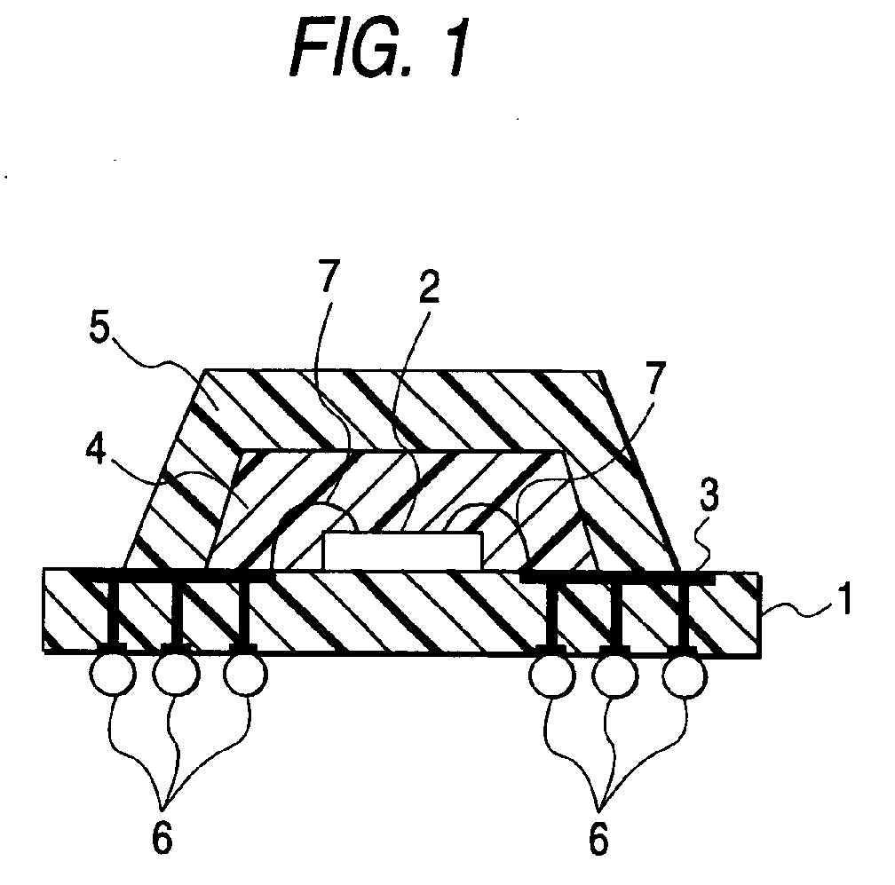
- FIG. 1 shows a single-side encapsulated semiconductor device, in which a semiconductor element 2 is mounted on a wiring circuit board 1 in which a circuit 3 has been formed.
- the semiconductor element 2 is resin-encapsulated with a first encapsulating resin layer 4.
- a second encapsulating resin layer 5 is formed on the outer circumference of the first encapsulating resin layer 4.
- the reference numeral 6 represents a connection electrode portion provided on the back side of the wiring circuit board 1; and 7, a bonding wire for connecting the semiconductor element 2 and the circuit 3.
- Fig. 2 shows another embodiment of a semiconductor device according to the invention.
- a lead frame 10 on which a semiconductor element 2 is mounted is wholly resin-encapsulated with a first encapsulating resin layer 4'.
- a second encapsulating resin layer 5' is formed on the outer circumference of the first encapsulating resin layer 4'.
- the reference numeral 7' represents a bonding wire for connecting the semiconductor element 2 and the lead frame 10.
- Mn-Zn-based soft ferrite whose average particle size was 3 ⁇ m and spherical silica fine powder whose primary particle size was about 12 nm were prepared. Then, the Mn-Zn-based soft ferrite and the spherical silica fine powder compounded so that the ratio of the latter to the former was 10 parts to 100 parts were thrown into a surface treatment apparatus having a rotor rotating at a high velocity, a stator and a circulating circuit. The surface treatment apparatus was operated for 3 minutes at the rotation speed of 4,800 rpm. Then, conjugated inorganic particles in which the Mn-Zn-based soft ferrite was insulated and coated with the spherical silica fine powder were discharged from this apparatus. Thus, the conjugated inorganic particles were produced.
- Ni-Zn-based ferrite powder (average particle size 10 ⁇ m, maximum particle size 100 ⁇ m) were used directly without surface treatment. The other things were set similarly to those in the epoxy resin composition a . Thus, a powdery epoxy resin composition A of 10 mesh passed was obtained.
- Amorphous nickel particles whose average particle size was 10 ⁇ m and spherical silica fine powder whose average particle size was 100 nm were prepared. Then, the amorphous nickel particles and the spherical silica fine powder compounded so that the ratio of the latter to the former was 20 parts to 100 parts were thrown into a surface treatment apparatus having a rotor rotating at a high velocity, a stator and a circulating circuit. The surface treatment apparatus was operated for 10 minutes at the rotation speed of 2, 600 rpm. Then, conjugated inorganic particles in which the amorphous nickel particles were insulated and coated with the spherical silica fine powder were discharged from this apparatus. Thus, the conjugated inorganic particles were produced.
- a powdery epoxy resin composition b as the material for forming the second encapsulating resin layer was obtained in the same manner as in Embodiment 1.
- the loading of the conjugated inorganic particles was changed to 62 parts, while 357 parts of fused silica powder having an average particle size of 35 ⁇ m were used.
- the other things were set similarly to those in the epoxy resin composition a in Example 1.
- an aimed powdery epoxy resin composition c of 10 mesh passed was obtained.
- the epoxy resin composition A produced in Example 1 was used.
- the loading of the conjugated inorganic particles was changed to 1,809 parts.
- the other things were set similarly to those in the epoxy resin composition a in Example 1.
- an aimed powdery epoxy resin composition d of 10 mesh passed was obtained.
- the epoxy resin composition B produced in Example 2 was used.
- Spherical silica fine powder whose primary particle size was about 500 nm was used in place of the spherical silica fine powder whose primary particle size was about 12 ⁇ m.
- the other things were set similarly to those in the epoxy resin composition a in Example 1.
- an aimed powdery epoxy resin composition e of 10 mesh passed was obtained.
- the epoxy resin composition B produced in Example 2 was used.
- Spherical silica fine powder whose primary particle size was about 5 nm was used in place of the spherical silica fine powder whose primary particle size was about 12 ⁇ m.
- the other things were set similarly to those in the epoxy resin composition b in Example 2.
- an aimed powdery epoxy resin composition f of 10 mesh passed was obtained.
- the epoxy resin composition B produced in Example 2 was used.
- the epoxy resin composition B produced in Example 2 was used for both the material for forming the second encapsulating resin layer and the material for forming the first encapsulating resin layer.
- the amorphous nickel powder used in the epoxy resin composition b in Example 2 was used directly without surface treatment. The other things were set similarly to those in the epoxy resin composition b in Example 2. Thus, an aimed powdery epoxy resin composition g of 10 mesh passed was obtained.
- the epoxy resin composition B produced in Example 2 was used.
- Each powdery epoxy resin composition was compressed into a tablet with a diameter of 38 mm. After that, the tablet was molded under the conditions that the molding pressure was 6.86 MPa, the mold temperature was 175°C and the molding time was 2 minutes. Then, post-hardening was performed at 175°C for 5 hours so as to produce a lamellar molded product measuring 80 mm by 80 mm by 2 mm in thickness.
- the obtained lamellar molded product was fixed to a specimen holder between a transmitting antenna and a receiving antenna, and the electromagnetic wave shielding properties were measured in a range up to at a measuring frequency of 1, 000 MHz by a spectrum analyzer (generally called TR-17031 method). Then, the shielding properties (electromagnetic wave shielding properties) at 500 MHz were evaluated with respect to an electric field component and a magnetic field component respectively.
- each powdery epoxy resin composition By use of each powdery epoxy resin composition, a disc-shaped cured product measuring 3 mm in thickness by 50 mm in diameter was produced in the same manner as in the measurement of the electromagnetic wave shielding properties. Then, silver electrodes were produced by use of silver paste so that the diameter of a main electrode was 30 mm, the diameter of a guard electrode was 32 mm, and the diameter of an opposed electrode was 45 mm. After that, DC voltage of 500 V was applied to the cured product to measure the volume resistivity (based on JIS K 6911).
- a CMOS 2 measuring 1.23 mm by 1.18 mm was mounted on an FR-4 resin wiring circuit board 1, and the CMOS 2 and a circuit 3 of the wiring circuit board 1 were electrically connected by gold wires 7.
- This arrangement was used together with the respective powdery epoxy resin compositions (the first encapsulating resin layer forming material and the second encapsulating resin layer forming material) . That is, first, the CMOS 2 was resin-encapsulated with the first encapsulating resin layer forming material A or B by transfer molding (at 175°C for 2 minutes from injection to molding) so that a first encapsulating resin layer 4 was formed.
- the second encapsulating resin layer forming material a to g was used to form a second encapsulating resin layer 5 (1 mm thick) on the outer circumference of the first encapsulating resin layer 4 by transfer molding (at 175°C for 2 minutes from injection to molding) .
- a ball grid array (BGA) resin-encapsulated package as a resin-encapsulated semiconductor device in which the second encapsulating resin layer 5 was formed on the outer circumference of the first encapsulating resin layer 4 was produced.
- a leakage current value between leads of the double-molded BGA resin-encapsulated package was measured.
- the symbol “o” was given when the measured leakage current value was less than three times as large as that in the case of the FR-4 resin wiring circuit board alone before molding.
- the symbol “ ⁇ ” was given when the measured leakage current value was three or more times as large.
- Example 1 first encapsulating resin layer forming material A - B - second encapsulating resin layer forming material - a - b electromagnetic wave shielding properties at 500MHz electric field component (dB) -15 -30 0 -43 magnetic field component (dB) -11 -25 0 -39 volume resistivity ( ⁇ cm) 3.1 ⁇ 10 13 2.2 ⁇ 10 14 3.8 ⁇ 10 16 1.1 ⁇ 10 13 noise radiation level (dB ⁇ V) 71 72 Lead-to-lead leakage current o o
- Example 3 4 first encapsulating resin layer forming material A - B - second encapsulating resin layer forming material - c - d electromagnetic wave shielding properties at 500MHz electric field component (dB) -15 -5 0 -50 magnetic field component (dB) -11 -3 0 -48 volume resistivity ( ⁇ cm) 3.1 ⁇ 10 13 3.6 ⁇ 10 15 3.8 ⁇ 10 16 1.0 ⁇ 10 13 noise radiation level (dB ⁇ V) 77 70 Lead-to-lea
- a semiconductor device is designed so that a semiconductor element is resin-encapsulated with first and second encapsulating resin layers in a double-layer structure in which the second encapsulating resin layer is formed on the outer circumference of the first encapsulating resin layer.
- the second encapsulating resin layer is formed from an epoxy resin composition containing special conjugated inorganic particles (component D) whose surfaces are subjected to coating treatment with an insulating inorganic material. Accordingly, the second encapsulating resin layer has not only electric insulation properties but also an electromagnetic wave shielding function.
- the semiconductor device according to the invention is excellent in EMC.
- the semiconductor device according to the invention is a resin-encapsulated semiconductor device which can cope with the advance of higher frequency in addition to various features belonging to the related art, that is, in addition to excellent reliability, excellent mass productivity and low price.
Abstract
Description
- The present application is based on Japanese Patent Application No. 2001-177509, which is incorporated herein by reference.
- The present invention relates to a semiconductor device resin-encapsulated with a cured resin piece having adequate electric insulation properties and an electromagnetic wave shielding function, and an epoxy resin composition used for encapsulating a semiconductor in the semiconductor device.
- Generally,the problem of EMC (Electro-Magnetic Compatibility) has been obvious in electric equipment. Measures against the problem have been taken from the two perspectives: emission of unnecessary electromagnetic waves and durability. In recent years, with the advance of miniaturization and higher functions of information communication equipment, semiconductor elements have a tendency to further increase their operating frequencies in order to have higher performance. Particularly with digital signals processed at a higher rate, amplitude values of the signals become lower in order to reduce power consumption. Thus, there is increasing a risk that even weak radio-frequency noise causes a malfunction.
- Covering of a semiconductor package with a metal cap has been heretofore carried out as one measure against this risk. However, since an extra mounting space is required, the mounting density of electronic parts cannot increase satisfactorily. Accordingly, other solutions have been under investigation. Nowadays, from such a background, an electromagnetic wave shielding technique suitable for high-density mounting is demanded. If an epoxy resin composition itself used as a encapsulating material has an electromagnetic wave shielding function, electronic parts can be mounted at a high density. Therefore, investigations have been made chiefly into the addition of the electromagnetic wave shielding function to the epoxy resin composition. However, any related-art cured piece made of an epoxy resin composition in which inorganic filler chiefly composed of silica powder has been mixed and dispersed has no electromagnetic wave shielding function at all.
- From such a point of view, for example, as a technique for adding an electromagnetic wave shielding function directly to an encapsulating resin material for encapsulating a semiconductor element, a resin-encapsulated semiconductor device having a double-layer structure of encapsulating resin layers has been proposed as disclosed in Unexamined Japanese Patent Publication Hei. 3- 23654. One of the encapsulating resin layers is a encapsulating resin layer in which the outside portion of a semiconductor package is encapsulated with resin in which ferromagnetic particles has been dispersed, and the other is an encapsulating resin layer in which the inside portion of the semiconductor package is encapsulated with related-art insulating encapsulating resin. Thus, there is disclosed a technique which can prevent malfunction of a semiconductor element from occurring due to electromagnetic noise. However, some resin in which ferrite or the like has been mixed and dispersed is often inferior in electric insulation properties due to its insufficient specific resistance. Thus, there has been a fear that a leakage current is increased when resin encapsulating is performed between wires or over parts of leads.
- On the other hand, similarly to the semiconductor device, another resin-encapsulated semiconductor device is disclosed in Unexamined Japanese Patent Publication No. Hei. 5-129476. That is, this resin-encapsulated semiconductor device has a double-layer structure of encapsulating resin layers, one of which is an encapsulating resin layer for encapsulating the outside portion of the semiconductor package with an encapsulating material mixed with a radio wave absorbing material for shielding from electromagnetic waves, while the other is an encapsulating resin layer for encapsulating the inside portion with related-art insulating encapsulating resin. In this semiconductor device, resin-encapsulating using an encapsulating material mixed with radio wave absorber particles coated with resin or rubber whose melting point is not lower than the melting point of the encapsulating material is proposed as a measure against leakage among pins of lead frames or among wirings of a printed board. However, because of coating with an organic material such as resin or rubber in such a manner, there has been a problem that the hardness is so low that sufficient electric insulation properties are hardly kept under high mechanical shearing in a melt kneading process of the encapsulating material.
- The invention was developed in consideration of such circumferences. An object of the invention is to provide a semiconductor device resin-encapsulated with an encapsulating material superior in electric insulation properties so as to have an electromagnetic wave shielding function, and an epoxy resin composition used for encapsulating a semiconductor in the semiconductor device.
- In order to attain the foregoing object, an epoxy resin composition according to a first gist of the invention, as a material for forming a second encapsulating resin layer is to be formed on an outer circumference of a first encapsulating resin layer for encapsulating a semiconductor element, and the epoxy resin composition contains the following components (A) to (D) :
- (A) epoxy resin;
- (B) phenolic resin;
- (C) curing accelerator; and
- (D) at least one of the following particles (d1) and (d2) :
- (d1) conductive particles whose surfaces are subjected to coating treatment with an insulating inorganic material; and
- (d2) magnetic particles whose surfaces are subjected to coating treatment with an insulating inorganic material.
-
- In addition, a semiconductor device according to a second gist of the invention comprises a semiconductor element; a first encapsulating resin layer for encapsulating the semiconductor element; and the second encapsulating resin layer being made of the aforementioned epoxy resin composition and being formed on the outer circumference of the first encapsulating resin layer.
- That is, in order to obtain a resin-encapsulated semiconductor device superior in electromagnetic wave shielding function, the inventor et al. conducted a series of investigations chiefly into compounding materials of an epoxy resin composition which is used for the resin encapsulating and which is superior in electric insulation properties. As a result, the inventor et al. found that not only an electromagnetic wave shielding function but also electric insulation properties were improved conspicuously when a semiconductor element is resin-encapsulated with encapsulating resin layers in a double-layer structure, and special conjugated inorganic particles [component (D)] obtained by coating the surfaces of conductive particles or magnetic particles with an insulating inorganic material are used as a material for forming the second encapsulating resin layer of the double-layer structure disposed in the outside portion. Thus, the inventor et al. achieved the invention.
- Features and advantages of the invention will be evident from the following detailed description of the preferred embodiments described in conjunction with the attached drawings.
- In the accompanying drawings:
- Fig. 1 is a sectional view showing an embodiment of a semiconductor device according to the invention; and
- Fig. 2 is a sectional view showing another embodiment of the semiconductor device according to the invention.
-
- Next, description will be made in detail about an embodiment of the invention.
- A semiconductor device according to the invention has a semiconductor element resin-encapsulated with a double-layer structure of encapsulating resin layers in which a second encapsulating resin layer is formed on the outer circumference of a first encapsulating resin layer. The second encapsulating resin layer is formed from a specific epoxy resin composition.
- The specific epoxy resin composition for forming the second encapsulating resin layer is obtained by use of epoxy resin (component A), phenolic resin (component B), curing accelerator (component C), and special conjugated inorganic particles (component D). The epoxy resin composition is normally formed into powder after melting and mixing of the resin composition or a tablet obtained by compressing the powder.
- The epoxy resin (component A) is not limited specifically. Any epoxy resin known heretofore may be used if it exhibits solidity at room temperature (25°C). Examples of the epoxy resin include biphenyl type epoxy resin, phenol novolac type epoxy resin, and cresol novolac type epoxy resin. Each of these resins may be used alone. Alternatively, two or more kinds of the resins may be used together.
- The phenol resin (component B) used together with the component A is not limited specifically. Any phenol resin known heretofore may be used if it has effect as hardener for the epoxy resin (component A) and exhibits solidity at room temperature (25°C). Examples of the phenol resin include phenol novolac, cresol novolac, bisphenol A type novolac, naphthol novolac, and phenol aralkyl resin. Each of these resins may be used alone. Alternatively, two or more kinds of the resins may be used together.
- The compounding ratio between the epoxy resin (component A) and the phenolic resin (component B) is preferably set so that the ratio of the hydroxyl equivalent weight in the phenolic resin to the epoxy equivalent weight in the epoxy resin is in a range of 0.5-1.6. More preferably, the ratio is set to be in a range of 0.8-1.2.
- The curing accelerator (component C) used together with the components A and B is not limited specifically. Any curing accelerator known heretofore may be used. Examples of the curing accelerator include
1, 8-diazabicyclo(5.4.0)undec-7-ene, tertiary amines such as triethylene diamine, imidazoles such as 2-methylimidazole, and phosphate-based curing accelerator such as triphenylphosphine or tetraphenylphosphonium tetraphenylborate. Each of these accelerators may be used alone. Alternatively, two or more kinds of the accelerators may be used together. - The content of the curing accelerator (component C) is normally set to be in a range of 0.5-10 parts by weight (hereinafter abbreviated to "parts") per 100 parts of the phenolic resin (component B).
- The special conjugated inorganic particles (component D) used together with the components A to C are made of at least one of conductive particles (d1) whose surfaces have been subjected to coating treatment with an insulating inorganic material and magnetic particles (d2) whose surfaces have been subjected to coating treatment with an insulating inorganic material.
- Examples of the conductive particles and the magnetic particles (d1 and d2) to be treated with the insulating inorganic material include various kinds of metal powders, alloy powders, or magnetic powders of copper, iron, nickel, gold, silver, aluminum, zinc, stainless steel, hematite (Fe2O3), magnetite (Fe3O4), various ferrites expressed by a general formula MFe2O4 or MO·nFe2O3 (in both the formulae, M designates a bivalent metal particle, including Mn, Co, Ni, Cu, Zn, Ba, Mg, etc; on the other hand, n designates a positive number; and further, as the particles M, the same kind of particles or different kinds of particles may be repeated) , silicon steel powder, permalloy, Co-group amorphous alloy, sendust, alperm, supermalloy, Mu-metal, permendur, and perminvar. Each of these powders may be used alone. Alternatively, two or more kinds of the powders may be used together.
- It is preferable that particles whose maximum particle size is not larger than 200 µm and whose average particle size is in a range of 0.5-50 µm are used as the conductive particles and the magnetic particles. The average particle size is especially preferably in a range of 2-30 µm. The maximum particle size and the average particle size can be, for example, measured with a laser diffraction/scattering type particle size distribution measuring apparatus.
- The insulating inorganic material used in the surface treatment for the conductive particles and the magnetic particles has electric insulation properties. Examples of the insulating inorganic material include silica fine powder, alumina fine powder, etc. Especially, the silica fine powder is used preferably. Of the silica fine powder, spherical silica fine powder, triturated silica fine powder, and granular type silica fine powder are preferable. In addition, from the point of view of fine particle size, the silica fine powder whose average primary particle size is 1-1,000 nm is preferably used. Especially, the silica fine powder whose average primary particle size is 10-500 nm is preferable.
- The special conjugated inorganic particles (component D) composed of the conductive particles (d1) whose surfaces have been subjected to coating treatment with the insulating inorganic material and/or the magnetic particles (d2) whose surfaces have been subjected to coating treatment with the insulating inorganic material can be, for example, produced in the following manner. That is, at least one of the conductive particles and the magnetic particles, and the insulating inorganic material are thrown into a surface treatment apparatus having a rotor rotating at high velocity, a stator and a circulating circuit. A conjugating method known heretofore, such as a treatment method in which the particles and the insulating inorganic material repeatedly suffer mechanical actions using mechanical impulsive force such as compression, friction, or shearing is used so that the special conjugated inorganic particles (component D) can be produced. By such a treatment, the surfaces of the conductive particles and/or the magnetic particles are coated with the insulating inorganic material so that the so-called conjugated inorganic particles whose surfaces have been coated with the insulating inorganic material can be obtained.
- The content of the special conjugated inorganic particles (component D) is preferably set in a range of 10-90 weight% of the total weight of the epoxy resin composition as the material for forming the second encapsulating resin layer. The content is more preferably 20-85 weight%, and especially more prefer ably 40-80 weight%. That is, when the content of the special conjugated inorganic particles (component D) is below 10 weight% and too small, the electromagnetic wave shielding effect of the cured piece itself made of the epoxy resin composition as the material for forming the second encapsulating resin layer becomes so insufficient that it becomes difficult to obtain a desired effect. On the contrary, when the content is over 90 weight% and too large, the molten viscosity at the time of low-pressure transfer molding becomes so high that there is seen a tendency that the fluidity deteriorates.
- Inorganic filler may be normally used together with the components A to D in the epoxy resin composition as the material for forming the second encapsulating resin layer. The inorganic filler is not limited specifically. Various inorganic fillers known heretofore may be used. Examples of the inorganic fillers include silica powder such as fused silica powder or crystalline silica powder, calcium carbonate powder, titanium white, alumina powder or silicon nitride powder. Each of these fillers maybe used alone. Alternatively, two or more kinds of the fillers may be used together. Of these fillers, the silica powder is used preferably because it can reduce the linear expansion coefficient of an obtained cured piece of the epoxy resin composition. Further, of the silica powder, spherical silica powder, triturated fine powder, and granular type silica powder are preferably used. Especially, the spherical fused silica powder is preferably used. In addition, as the inorganic filler, it is preferable to use inorganic filler whose maximum particle size is not larger than 100 µm. Normally, the lower limit of the maximum particle size is about 0.1 µm. Further, in addition to such a maximum particle size, it is preferable to use the inorganic filler whose average particle size is in a range of 1-40 µm. Incidentally, the maximum particle size and the average particle size can be, for example, measured with a laser diffraction/scattering type particle size distribution measuring apparatus in the same manner as those of the conductive particles d1 and the magnetic particles d2.
- It is preferable that the content of the inorganic filler is set to be not higher than 50 weight% of the total weight of the epoxy resin composition. The content is more preferably not higher than 30 weight%. That is, when the content of the inorganic filler is above 50 weight% and too large, the molten viscosity of the epoxy resin composition becomes so high that there is seen a tendency that the filling properties deteriorate.
- If necessary, additives other than the components A to D and the inorganic filler may be appropriately mixed into the epoxy resin composition as the material for forming the second encapsulating resin layer.
- Examples of the additives include a stress reduction agent, pigment, a mold release agent, a coupling agent, and a fire retardant.
- Examples of the stress reduction agent include silicone compounds such as side-chain ethylene glycol type dimethylsiloxane, and acrylonitrile-butadiene rubber.
- Examples of the pigment include carbonblack, and titanium oxide. On the other hand, examples of the mold release agent include polyethylene wax, carnauba wax, and fatty acid salts.
- Examples of the coupling agent include silane coupling agents such as γ-glycidoxy propyltrimethoxysilane, and β-(3,4-epoxycyclohexyl)ethyltrimethoxysilane.
- An example of the fire retardant includes brominating epoxy resin. In addition thereto, a fire retardant auxiliary such as antimony trioxide is used.
- Further, other than the fire retardant, polyhedral conjugated metal hydroxide expressed by the following formula (1) may be used. This metal hydroxide has a polyhedral crystal shape. The metal hydroxide does not have a usual hexagonal lamellar shape or a so-called thin tabular crystal shape such as a flaky shape, but has a granular crystal shape such as an approximately dodecahedral shape, an approximately octahedral shape or an approximately tetrahedral shape, in which the crystal growth is great in the thickness direction (c-axis direction) as well as lengthwise and crosswise, for example, a lamellar crystal has grown in the thickness direction (c-axis direction) so as to be cubed and approximated to a sphere.
M1-xQx(OH)2 - The metal hydroxide having a polyhedral crystal shape can be obtained as follows. That is, crystal growth in the thickness direction (c-axis direction) as well as lengthwise and crosswise is increased, for example, by controlling various conditions in the process for producing metal hydroxide. Thus, metal hydroxide having a desired polyhedral shape such as an approximately dodecahedral shape, an approximately octahedral shape or an approximately tetrahedral shape, can be obtained. Generally, the metal hydroxide is made of a mixture of such metal hydroxides.
- Specific prototypes of such metal hydroxides having polyhedral shapes can be expressed by the formula Mg1-xNix (OH) 2 [0.01<X<0.5], Mg1-xZnx(OH)2 [0.01<X<0.5], and the like. One of examples of commercial products of such metal hydroxides is ECHORMAG made by Tateho Chemical Industries Co., Ltd.
- In addition, the aspect ratio of the metal hydroxide having a polyhedral shape is normally 1-8, preferably 1-7, and more preferably 1-4. The aspect ratio here means the ratio of the major axis of the metal hydroxide to the minor axis thereof. That is, when the aspect ratio exceeds 8, an epoxy resin composition containing this metal hydroxide is short of effect on the lowering of viscosity when the epoxy resin composition melts.
- For example, the epoxy resin composition as the material for forming the second encapsulating resin layer can be produced as follows. That is, predetermined loadings of epoxy resin (component A), phenolic resin (component B), curing accelerator (component C), special conjugated inorganic particles (component D), and further, if necessary, other additives such as inorganic filler, a stress reduction agent, pigment, a mold release agent, a coupling agent, and a fire retardant are compounded and mixed adequately by melt dispersion by use of a heated roll, an extruder, a kneader or the like. Then, the mixture is cooled and ground. The ground mixture may be compression-molded into a tablet as occasion demands. By such a series of steps, it is possible to produce an aimed epoxy resin composition as the material for forming the second encapsulating resin layer.
- On the other hand, for the epoxy resin composition as the material for forming the first resin layer formed on the inner circumference of the second encapsulating resin layer, components similar to those of the epoxy resin composition as the material for forming the second encapsulating resin layer are used except that the special conjugated inorganic particles (component D) used in the material for forming the second encapsulating resin layer is not used. An example of the epoxy resin composition as the material for forming the first resin layer will be described. Similarly to those used in the epoxy resin composition for the second encapsulating resin layer, inorganic filler known heretofore, such as fused silica powder, crystalline silica powder, titanium white, alumina powder or silicon nitride powder; inorganic filler such as magnetic particles of ferrite in a range not to lower the insulation properties; and further, if necessary, other additives such as a stress reduction agent, pigment, a mold release agent, a coupling agent, and a fire retardant such as conjugated metal hydroxide may be mixed appropriately together with the components A to C. Then, in the similar manner to the epoxy resin composition as the material for forming the second encapsulating resin layer, predetermined loadings of such various components are compounded and mixed adequately by melt dispersion by use of a heated roll, an extruder, a kneader or the like. Then, the mixture is cooled and ground. The ground mixture may be compression-molded into a tablet as occasion demands. By such a series of steps, it is possible to produce an aimed epoxy resin composition as the material for forming the first encapsulating resin layer.
- Alternatively, liquid epoxy resin composition known heretofore may be used for the epoxy resin composition as the material for forming the first encapsulating resin layer. For example, the liquid epoxy resin composition is a combination of epoxy resin known heretofore, for example, taking on a liquid state at room temperature (25°C), such as bisphenol-A type epoxy resin or bisphenol-F type epoxy resin, and liquid hardener such as liquid acid anhydride or liquid phenol novolac. If necessary, curing accelerator, and inorganic filler known heretofore, such as fused silica powder, crystalline silica powder, titanium white, alumina powder or silicon nitride powder, may be mixed. Further, if necessary, a stress reduction agent, pigment, a coupling agent, any one fire retardant, etc., may be mixed suitably.
- The method of encapsulating a semiconductor element by use of the epoxy resin composition as the material for forming the first encapsulating resin layer and the epoxy resin composition as the material for forming the second encapsulating resin layer obtained thus is not limited specifically. The encapsulating may be carried out by a known molding method such as normal low-pressure transfer molding. To Describe it more in detail, first, a semiconductor element is resin-encapsulated, by low-pressure transfer molding, with the material for forming the first encapsulating resin layer. Next, a second encapsulating resin layer is formed on the outer circumference of the first encapsulating resin layer, by low-pressure transfer molding, from the material for forming the second encapsulating resin layer.
- It is preferable that the second encapsulating resin layer of the semiconductor device obtained thus is formed to have a thickness in a range of 0.1-5 mm in consideration of the electromagnetic wave shielding function.
- An embodiment of semiconductor devices resin-encapsulated with the first encapsulating resin layer forming material and the second encapsulating resin layer forming material will be shown. Fig. 1 shows a single-side encapsulated semiconductor device, in which a
semiconductor element 2 is mounted on a wiring circuit board 1 in which acircuit 3 has been formed. Thesemiconductor element 2 is resin-encapsulated with a firstencapsulating resin layer 4. Then, a secondencapsulating resin layer 5 is formed on the outer circumference of the first encapsulatingresin layer 4. In Fig. 1, thereference numeral 6 represents a connection electrode portion provided on the back side of the wiring circuit board 1; and 7, a bonding wire for connecting thesemiconductor element 2 and thecircuit 3. - Further, Fig. 2 shows another embodiment of a semiconductor device according to the invention. In this semiconductor device, first, a
lead frame 10 on which asemiconductor element 2 is mounted is wholly resin-encapsulated with a first encapsulating resin layer 4'. Further, a second encapsulating resin layer 5' is formed on the outer circumference of the first encapsulating resin layer 4'. In Fig. 2, the reference numeral 7' represents a bonding wire for connecting thesemiconductor element 2 and thelead frame 10. - Next, description will be made about examples together with comparative examples.
- Mn-Zn-based soft ferrite whose average particle size was 3 µm and spherical silica fine powder whose primary particle size was about 12 nm were prepared. Then, the Mn-Zn-based soft ferrite and the spherical silica fine powder compounded so that the ratio of the latter to the former was 10 parts to 100 parts were thrown into a surface treatment apparatus having a rotor rotating at a high velocity, a stator and a circulating circuit. The surface treatment apparatus was operated for 3 minutes at the rotation speed of 4,800 rpm. Then, conjugated inorganic particles in which the Mn-Zn-based soft ferrite was insulated and coated with the spherical silica fine powder were discharged from this apparatus. Thus, the conjugated inorganic particles were produced.
- Next, 419 parts of the conjugated inorganic particles, 100 parts of o-cresol novolac type epoxy resin (epoxy equivalent weight 195, softening point 75°C), 60 parts of phenol novolac resin hardener (hydroxyl equivalent weight 106, softening point 82°C), 1 part of triphenylphosphine, 20 parts of brominated phenol novolac type epoxy resin (epoxy equivalent weight 280), 15 parts of antimony trioxide, 2 parts of carbon black, 1 part of silane coupling agent, and 2 parts of polyethylene wax were compounded together, melted and kneaded for 3 minutes by a heated rollheated to 95-100°C, and cooled. Thus, a powdery epoxy resin composition a of 10 mesh passed was obtained.
- On the other hand, in addition to the epoxy resin composition a, 419 parts of Ni-Zn-based ferrite powder (
average particle size 10 µm, maximum particle size 100 µm) were used directly without surface treatment. The other things were set similarly to those in the epoxy resin composition a. Thus, a powdery epoxy resin composition A of 10 mesh passed was obtained. - Amorphous nickel particles whose average particle size was 10 µm and spherical silica fine powder whose average particle size was 100 nm were prepared. Then, the amorphous nickel particles and the spherical silica fine powder compounded so that the ratio of the latter to the former was 20 parts to 100 parts were thrown into a surface treatment apparatus having a rotor rotating at a high velocity, a stator and a circulating circuit. The surface treatment apparatus was operated for 10 minutes at the rotation speed of 2, 600 rpm. Then, conjugated inorganic particles in which the amorphous nickel particles were insulated and coated with the spherical silica fine powder were discharged from this apparatus. Thus, the conjugated inorganic particles were produced.
- Next, a powdery epoxy resin composition b as the material for forming the second encapsulating resin layer was obtained in the same manner as in Embodiment 1.
- 419 parts of spherical fused silica powder (average particle size 20 µm, maximum particle size 128 µm) were used in place of the Ni-Zn-based ferrite powder. The other things were set similarly to those in the epoxy resin composition A in Example 1. Thus, a powdery epoxy resin composition B of 10 mesh passed was obtained.
- The loading of the conjugated inorganic particles was changed to 62 parts, while 357 parts of fused silica powder having an average particle size of 35 µm were used. The other things were set similarly to those in the epoxy resin composition a in Example 1. Thus, an aimed powdery epoxy resin composition c of 10 mesh passed was obtained.
- The epoxy resin composition A produced in Example 1 was used.
- The loading of the conjugated inorganic particles was changed to 1,809 parts. The other things were set similarly to those in the epoxy resin composition a in Example 1. Thus, an aimed powdery epoxy resin composition d of 10 mesh passed was obtained.
- The epoxy resin composition B produced in Example 2 was used.
- Spherical silica fine powder whose primary particle size was about 500 nm was used in place of the spherical silica fine powder whose primary particle size was about 12 µm. The other things were set similarly to those in the epoxy resin composition a in Example 1. Thus, an aimed powdery epoxy resin composition e of 10 mesh passed was obtained.
- The epoxy resin composition B produced in Example 2 was used.
- Spherical silica fine powder whose primary particle size was about 5 nm was used in place of the spherical silica fine powder whose primary particle size was about 12 µm. The other things were set similarly to those in the epoxy resin composition b in Example 2. Thus, an aimed powdery epoxy resin composition f of 10 mesh passed was obtained.
- The epoxy resin composition B produced in Example 2 was used.
- The epoxy resin composition B produced in Example 2 was used for both the material for forming the second encapsulating resin layer and the material for forming the first encapsulating resin layer.
- The amorphous nickel powder used in the epoxy resin composition b in Example 2 was used directly without surface treatment. The other things were set similarly to those in the epoxy resin composition b in Example 2. Thus, an aimed powdery epoxy resin composition g of 10 mesh passed was obtained.
- The epoxy resin composition B produced in Example 2 was used.
- Upon each epoxy resin composition obtained thus, electromagnetic wave shielding properties, volume resistivity, noise radiation level, and a lead-to-lead leakage current were measured according to the following methods respectively. Tables 1 to 4 which will be described later show these results.
- Each powdery epoxy resin composition was compressed into a tablet with a diameter of 38 mm. After that, the tablet was molded under the conditions that the molding pressure was 6.86 MPa, the mold temperature was 175°C and the molding time was 2 minutes. Then, post-hardening was performed at 175°C for 5 hours so as to produce a lamellar molded product measuring 80 mm by 80 mm by 2 mm in thickness. The obtained lamellar molded product was fixed to a specimen holder between a transmitting antenna and a receiving antenna, and the electromagnetic wave shielding properties were measured in a range up to at a measuring frequency of 1, 000 MHz by a spectrum analyzer (generally called TR-17031 method). Then, the shielding properties (electromagnetic wave shielding properties) at 500 MHz were evaluated with respect to an electric field component and a magnetic field component respectively.
- By use of each powdery epoxy resin composition, a disc-shaped cured product measuring 3 mm in thickness by 50 mm in diameter was produced in the same manner as in the measurement of the electromagnetic wave shielding properties. Then, silver electrodes were produced by use of silver paste so that the diameter of a main electrode was 30 mm, the diameter of a guard electrode was 32 mm, and the diameter of an opposed electrode was 45 mm. After that, DC voltage of 500 V was applied to the cured product to measure the volume resistivity (based on JIS K 6911).
- As shown in Fig. 1, a
CMOS 2 measuring 1.23 mm by 1.18 mm was mounted on an FR-4 resin wiring circuit board 1, and theCMOS 2 and acircuit 3 of the wiring circuit board 1 were electrically connected bygold wires 7. This arrangement was used together with the respective powdery epoxy resin compositions (the first encapsulating resin layer forming material and the second encapsulating resin layer forming material) . That is, first, theCMOS 2 was resin-encapsulated with the first encapsulating resin layer forming material A or B by transfer molding (at 175°C for 2 minutes from injection to molding) so that a firstencapsulating resin layer 4 was formed. Next, the second encapsulating resin layer forming material a to g was used to form a second encapsulating resin layer 5 (1 mm thick) on the outer circumference of the first encapsulatingresin layer 4 by transfer molding (at 175°C for 2 minutes from injection to molding) . Thus, a ball grid array (BGA) resin-encapsulated package as a resin-encapsulated semiconductor device in which the secondencapsulating resin layer 5 was formed on the outer circumference of the first encapsulatingresin layer 4 was produced. While the obtained BGA resin-encapsulated package was operated at 20 MHz, scanning at a pitch of 5 mm was carried out 10 mm above the package by use of an electromagnetic wave exploring probe so as to measure noise (in a range of 200-300 MHz) radiated from the package. - A leakage current value between leads of the double-molded BGA resin-encapsulated package was measured. The symbol "o" was given when the measured leakage current value was less than three times as large as that in the case of the FR-4 resin wiring circuit board alone before molding. On the other hand, the symbol "×" was given when the measured leakage current value was three or more times as large.
Example 1 2 first encapsulating resin layer forming material A - B - second encapsulating resin layer forming material - a - b electromagnetic wave shielding properties at 500MHz electric field component (dB) -15 -30 0 -43 magnetic field component (dB) -11 -25 0 -39 volume resistivity (Ω·cm) 3.1×10¹³ 2.2×10¹⁴ 3.8×10¹⁶ 1.1×10¹³ noise radiation level (dBµV) 71 72 Lead-to-lead leakage current o o Example 3 4 first encapsulating resin layer forming material A - B - second encapsulating resin layer forming material - c - d electromagnetic wave shielding properties at 500MHz electric field component (dB) -15 -5 0 -50 magnetic field component (dB) -11 -3 0 -48 volume resistivity (Ω·cm) 3.1×10¹³ 3.6×10¹⁵ 3.8×10¹⁶ 1.0×10¹³ noise radiation level (dBµV) 77 70 Lead-to-lead leakage current o o Example 5 6 first encapsulating resin layer forming material B - B - second encapsulating resin layer forming material - e - f electromagnetic wave shielding properties at 500MHz electric field component (dB) 0 -28 0 -48 magnetic field component (dB) 0 -22 0 -45 volume resistivity (Ω·cm) 3.8×10¹⁶ 5.0×10¹⁴ 3.8×10¹⁶ 1.2×10¹³ noise radiation level (dBµV) 76 71 Lead-to-lead leakage current o o Comparative Example 1 2 first encapsulating resin layer forming material B - B - second encapsulating resin layer forming material - B - g electromagnetic wave shielding properties at 500MHz electric field component (dB) 0 0 0 -50 magnetic field component (dB) 0 0 0 -46 volume resistivity (Ω·cm) 3.8×10¹⁶ 3.8×10¹⁶ 3.8×10¹⁶ 6.0×10³ noise radiation level (dBµV) 81 70 lead-to-lead leakage current o × - From the results of Tables 1 to 4, the effect of improvement in the values of the electromagnetic wave shielding properties in the products in Examples was obvious in comparison with those in the products in Comparative Examples. Further, it is proved that the products in Examples are also superior in the insulation resistance values.
- As described above, a semiconductor device according to the invention is designed so that a semiconductor element is resin-encapsulated with first and second encapsulating resin layers in a double-layer structure in which the second encapsulating resin layer is formed on the outer circumference of the first encapsulating resin layer. The second encapsulating resin layer is formed from an epoxy resin composition containing special conjugated inorganic particles (component D) whose surfaces are subjected to coating treatment with an insulating inorganic material. Accordingly, the second encapsulating resin layer has not only electric insulation properties but also an electromagnetic wave shielding function. Thus, the semiconductor device according to the invention is excellent in EMC.
- Thus, the semiconductor device according to the invention is a resin-encapsulated semiconductor device which can cope with the advance of higher frequency in addition to various features belonging to the related art, that is, in addition to excellent reliability, excellent mass productivity and low price.
- This invention should not be limited to the embodiments described above. Various modifications can be included in this invention within a range which can be easily realized by those skilled in the art without departing from the spirit of the scope of claim.
Claims (16)
- An epoxy resin composition as a material for forming a second encapsulating resin layer to be formed on an outer circumference of a first encapsulating resin layer for encapsulating a semiconductor element, said epoxy resin composition containing the following components (A) to (D):(A) epoxy resin;(B) phenolic resin;(C) curing accelerator; and(D) at least one of the following particles (d1) and (d2) :(d1) conductive particles whose surfaces are subjected to coating treatment with an insulating inorganic material; and(d2) magnetic particles whose surfaces are subjected to coating treatment with an insulating inorganic material.
- An epoxy resin composition according to claim 1, wherein each of said conductive particle and said magnetic particle is selected from a group consisting of copper, iron, nickel, gold, silver, aluminum, zinc, stainless steel, hematite and magnetite.
- An epoxy resin composition according to claim 1, wherein each of said conductive particle and said magnetic particle is one of MFe2O4 and MO·nFe2O3, wherein M designates a bivalent metal particle and n designates a positive number.
- An epoxy resin composition according to claim 3, wherein M is at least one selected from a group consisting of Mn, Co, Ni, Cu, Zn, Ba and Mg.
- An epoxy resin composition according to claim 1, wherein each of said conductive particle and said magnetic particle is at least one selected from a group consisting of silicon steel, permalloy, Co-group amorphous alloy, sendust, alperm, supermalloy, Mu-metal, permendur, and perminvar.
- An epoxy resin composition according to claim 1, wherein a particle size of each of said conductive particle and said magnetic particle is not larger than 200 µm.
- An epoxy resin composition according to claim 1, wherein said insulating inorganic material is one of silica fine powder and alumina fine powder.
- An epoxy resin composition according to claim 1, wherein a content of said insulating inorganic particle material is in a range of 10-90 weight% of a total weight of said epoxy resin composition.
- An epoxy resin composition according to claim 1, further comprising inorganic filler.
- An epoxy resin composition according to claim 9, wherein said inorganic filler is at least one selected from a group consisting of silica powder, calcium carbonate powder, titanium white, alumina powder and silicon nitride powder.
- An epoxy resin composition according to claim 9, wherein a particle size of said inorganic filler is not larger than 100 µm.
- An epoxy resin composition according to claim 9, wherein a content of said inorganic filler is not higher than 50 weight% of a total weight of said epoxy resin composition.
- An epoxy resin composition according to claim 1, further comprising polyhedral conjugated metal hydroxide expressed by the following formula,
- An epoxy resin composition according to claim 13, wherein said metal hydroxide is one of Mg1-xNix(OH)2 [0.01<X<0.5] and Mg1-xZnx(OH)2 [0.01<X<0.5].
- An epoxy resin composition according to claim 13, wherein an aspect ratio of said metal hydroxide is in a range of 1 to 8.
- A semiconductor device comprising: a semiconductor element; a first encapsulating resin layer for encapsulating said semiconductor element; and said second encapsulating resin layer according to claim 1 being formed on the outer circumference of said first encapsulating resin layer.
Applications Claiming Priority (2)
| Application Number | Priority Date | Filing Date | Title |
|---|---|---|---|
| JP2001177509 | 2001-06-12 | ||
| JP2001177509A JP3645197B2 (en) | 2001-06-12 | 2001-06-12 | Semiconductor device and epoxy resin composition for semiconductor encapsulation used therefor |
Publications (2)
| Publication Number | Publication Date |
|---|---|
| EP1266936A1 true EP1266936A1 (en) | 2002-12-18 |
| EP1266936B1 EP1266936B1 (en) | 2004-03-24 |
Family
ID=19018343
Family Applications (1)
| Application Number | Title | Priority Date | Filing Date |
|---|---|---|---|
| EP02013407A Expired - Fee Related EP1266936B1 (en) | 2001-06-12 | 2002-06-12 | Epoxy resin composition used for encapsulating semiconductor and semiconductor device using the composition |
Country Status (4)
| Country | Link |
|---|---|
| US (1) | US6800804B2 (en) |
| EP (1) | EP1266936B1 (en) |
| JP (1) | JP3645197B2 (en) |
| DE (1) | DE60200279T2 (en) |
Cited By (3)
| Publication number | Priority date | Publication date | Assignee | Title |
|---|---|---|---|---|
| EP1577947A1 (en) * | 2004-03-16 | 2005-09-21 | Texas Instruments Incorporated | Semiconductor device comprising an encapsulating material that attenuates electromagnetic interference |
| WO2011008442A1 (en) * | 2009-06-29 | 2011-01-20 | Spansion Llc | Electronic device having a molding compound including a composite material |
| US8946663B2 (en) | 2012-05-15 | 2015-02-03 | Spansion Llc | Soft error resistant circuitry |
Families Citing this family (70)
| Publication number | Priority date | Publication date | Assignee | Title |
|---|---|---|---|---|
| US20020190389A1 (en) * | 1995-11-15 | 2002-12-19 | Koenck Steven E. | Reduction of electromagnetic interference in integrated circuit device packages |
| SG106050A1 (en) * | 2000-03-13 | 2004-09-30 | Megic Corp | Method of manufacture and identification of semiconductor chip marked for identification with internal marking indicia and protection thereof by non-black layer and device produced thereby |
| JP3865601B2 (en) * | 2001-06-12 | 2007-01-10 | 日東電工株式会社 | Electromagnetic wave suppression sheet |
| JP2003347787A (en) * | 2002-05-23 | 2003-12-05 | Shin Etsu Chem Co Ltd | Electromagnetic wave absorbing composition |
| DE10332009B4 (en) * | 2003-07-14 | 2008-01-31 | Infineon Technologies Ag | Semiconductor device with electromagnetic shielding device |
| JP2005078442A (en) | 2003-09-01 | 2005-03-24 | Sony Corp | Ic card, and its manufacturing method |
| US20050093175A1 (en) * | 2003-11-03 | 2005-05-05 | Martin Reiss | Arrangement for improving the reliability of semiconductor modules |
| US7803457B2 (en) * | 2003-12-29 | 2010-09-28 | General Electric Company | Composite coatings for groundwall insulation, method of manufacture thereof and articles derived therefrom |
| KR100601761B1 (en) * | 2004-07-22 | 2006-07-19 | 삼성전자주식회사 | Method of manufacturing double molded semiconductor package |
| KR100575086B1 (en) * | 2004-11-11 | 2006-05-03 | 삼성전자주식회사 | Semiconductor package with conductive molding compound and manufacturing method thereof |
| JP4651004B2 (en) * | 2004-12-07 | 2011-03-16 | 戸田工業株式会社 | Spherical sintered ferrite particles, resin composition for semiconductor encapsulation using the same, and semiconductor device obtained using the same |
| US7956451B2 (en) * | 2004-12-18 | 2011-06-07 | Agere Systems Inc. | Packages for encapsulated semiconductor devices and method of making same |
| JP2007141977A (en) * | 2005-11-16 | 2007-06-07 | Matsushita Electric Ind Co Ltd | Semiconductor device |
| US20070200146A1 (en) * | 2006-02-28 | 2007-08-30 | Keiji Onishi | Electronic device, method for producing the same, and communication apparatus including the same |
| DE102006026023A1 (en) * | 2006-06-01 | 2007-12-06 | Infineon Technologies Ag | Semiconductor component, has plastic compound arranged between another plastic compound and edge sides of adhesive layer and chip and upper side of chip such that latter plastic compound does not have physical contact to chip and layer |
| TWI383477B (en) * | 2006-06-06 | 2013-01-21 | Nitto Denko Corp | Spherical sintered ferrite particles, resin composition for semiconductor encapsulation comprising them and semiconductor devices produced by using the same |
| WO2007141843A1 (en) * | 2006-06-06 | 2007-12-13 | Nitto Denko Corporation | Spherical sintered ferrite particle, semiconductor sealing resin composition making use of the same and semiconductor device obtained therewith |
| ATE488540T1 (en) * | 2006-06-16 | 2010-12-15 | Huntsman Adv Mat Switzerland | COATING SYSTEM |
| KR20080023996A (en) * | 2006-09-12 | 2008-03-17 | 주식회사 하이닉스반도체 | Semiconductor package |
| JP2008108782A (en) * | 2006-10-23 | 2008-05-08 | Nec Electronics Corp | Electronic equipment and manufacturing method thereof |
| US8009442B2 (en) * | 2007-12-28 | 2011-08-30 | Intel Corporation | Directing the flow of underfill materials using magnetic particles |
| US8350367B2 (en) | 2008-02-05 | 2013-01-08 | Advanced Semiconductor Engineering, Inc. | Semiconductor device packages with electromagnetic interference shielding |
| US8212339B2 (en) * | 2008-02-05 | 2012-07-03 | Advanced Semiconductor Engineering, Inc. | Semiconductor device packages with electromagnetic interference shielding |
| US7989928B2 (en) * | 2008-02-05 | 2011-08-02 | Advanced Semiconductor Engineering Inc. | Semiconductor device packages with electromagnetic interference shielding |
| US8022511B2 (en) | 2008-02-05 | 2011-09-20 | Advanced Semiconductor Engineering, Inc. | Semiconductor device packages with electromagnetic interference shielding |
| US8410584B2 (en) | 2008-08-08 | 2013-04-02 | Advanced Semiconductor Engineering, Inc. | Semiconductor device packages with electromagnetic interference shielding |
| EP2161974A1 (en) | 2008-09-09 | 2010-03-10 | Hegutechnik v. Gutwald KG | Bifunctional EMC coating |
| US20100110656A1 (en) | 2008-10-31 | 2010-05-06 | Advanced Semiconductor Engineering, Inc. | Chip package and manufacturing method thereof |
| US8110902B2 (en) * | 2009-02-19 | 2012-02-07 | Advanced Semiconductor Engineering, Inc. | Chip package and manufacturing method thereof |
| US8212340B2 (en) | 2009-07-13 | 2012-07-03 | Advanced Semiconductor Engineering, Inc. | Chip package and manufacturing method thereof |
| US8030750B2 (en) | 2009-11-19 | 2011-10-04 | Advanced Semiconductor Engineering, Inc. | Semiconductor device packages with electromagnetic interference shielding |
| US8378466B2 (en) | 2009-11-19 | 2013-02-19 | Advanced Semiconductor Engineering, Inc. | Wafer-level semiconductor device packages with electromagnetic interference shielding |
| US8368185B2 (en) | 2009-11-19 | 2013-02-05 | Advanced Semiconductor Engineering, Inc. | Semiconductor device packages with electromagnetic interference shielding |
| US8569894B2 (en) | 2010-01-13 | 2013-10-29 | Advanced Semiconductor Engineering, Inc. | Semiconductor package with single sided substrate design and manufacturing methods thereof |
| TWI411075B (en) | 2010-03-22 | 2013-10-01 | Advanced Semiconductor Eng | Semiconductor package and manufacturing method thereof |
| TWI540698B (en) | 2010-08-02 | 2016-07-01 | 日月光半導體製造股份有限公司 | Semiconductor package and manufacturing method thereof |
| US9545043B1 (en) * | 2010-09-28 | 2017-01-10 | Rockwell Collins, Inc. | Shielding encapsulation for electrical circuitry |
| US20120115382A1 (en) * | 2010-11-05 | 2012-05-10 | Nitto Denko Automotive, Inc. | Magnetic reinforcing composition, reinforcing sheet and methods for producing the same |
| US9406658B2 (en) | 2010-12-17 | 2016-08-02 | Advanced Semiconductor Engineering, Inc. | Embedded component device and manufacturing methods thereof |
| US8351221B2 (en) * | 2011-01-14 | 2013-01-08 | Rf Micro Devices, Inc. | Stacked shield compartments for electronic components |
| CN102181129B (en) * | 2011-03-31 | 2012-09-26 | 广州友益电子科技有限公司 | Epoxy resin composition for semiconductor encapsulation |
| US9141157B2 (en) * | 2011-10-13 | 2015-09-22 | Texas Instruments Incorporated | Molded power supply system having a thermally insulated component |
| CN102509722A (en) * | 2012-01-06 | 2012-06-20 | 日月光半导体制造股份有限公司 | Semiconductor encapsulating element and manufacture method thereof |
| CN103367331B (en) * | 2012-03-27 | 2016-12-14 | 南亚科技股份有限公司 | Encapsulating structure |
| US8704341B2 (en) | 2012-05-15 | 2014-04-22 | Advanced Semiconductor Engineering, Inc. | Semiconductor packages with thermal dissipation structures and EMI shielding |
| US8653634B2 (en) | 2012-06-11 | 2014-02-18 | Advanced Semiconductor Engineering, Inc. | EMI-shielded semiconductor devices and methods of making |
| EP2920226B1 (en) * | 2012-11-13 | 2016-12-28 | Dow Global Technologies LLC | Epoxy resin system containing polyethylene tetramines and triethylene diamine catalyst for resin transfer molding processes |
| JP2014164616A (en) * | 2013-02-26 | 2014-09-08 | Dainippon Printing Co Ltd | IC module |
| JP2014164617A (en) * | 2013-02-26 | 2014-09-08 | Dainippon Printing Co Ltd | IC module |
| US20140292460A1 (en) * | 2013-03-29 | 2014-10-02 | Samsung Electro-Mechanics Co., Ltd. | Inductor and method for manufacturing the same |
| JP6321944B2 (en) * | 2013-11-15 | 2018-05-09 | 三井金属鉱業株式会社 | Metal foil for press bonding and electronic component package |
| US9643272B2 (en) * | 2014-08-14 | 2017-05-09 | Apple Inc. | Encapsulation process enabling hotbar soldering without direct PCB support |
| KR101647587B1 (en) | 2015-03-03 | 2016-08-10 | 앰코 테크놀로지 코리아 주식회사 | Semiconductor package |
| KR20170039063A (en) * | 2015-09-30 | 2017-04-10 | 삼성에스디아이 주식회사 | Semiconductor package and method for manufacturing the same |
| WO2017057844A1 (en) * | 2015-09-30 | 2017-04-06 | 삼성에스디아이 주식회사 | Semiconductor package and manufacturing method thereof |
| US9807866B2 (en) * | 2015-11-30 | 2017-10-31 | Intel Corporation | Shielding mold for electric and magnetic EMI mitigation |
| KR20170109479A (en) * | 2016-03-21 | 2017-09-29 | 삼성에스디아이 주식회사 | Semiconductor package and method for manufacturing the same |
| JP7221579B2 (en) * | 2016-03-22 | 2023-02-14 | 富士電機株式会社 | resin composition |
| US20190035744A1 (en) * | 2016-03-31 | 2019-01-31 | Tdk Corporation | Electronic circuit package using composite magnetic sealing material |
| US10242954B2 (en) * | 2016-12-01 | 2019-03-26 | Tdk Corporation | Electronic circuit package having high composite shielding effect |
| US9907179B2 (en) * | 2016-04-25 | 2018-02-27 | Tdk Corporation | Electronic circuit package |
| JP6891639B2 (en) * | 2016-07-14 | 2021-06-18 | 住友ベークライト株式会社 | Semiconductor devices, manufacturing methods for semiconductor devices, epoxy resin compositions for encapsulating semiconductors, and resin sets |
| US10438889B2 (en) * | 2016-12-23 | 2019-10-08 | Advanced Semiconductor Engineering, Inc. | Semiconductor package device and method of manufacturing the same |
| CN110300780A (en) * | 2017-03-06 | 2019-10-01 | 迪睿合株式会社 | Resin combination, the preparation method of resin combination and structural body |
| US11619658B2 (en) * | 2017-12-08 | 2023-04-04 | Texas Instruments Incorporated | Semiconductor integrated fluxgate device shielded by discrete magnetic plate |
| KR20200013385A (en) * | 2018-07-30 | 2020-02-07 | 삼성에스디아이 주식회사 | Epoxy resin composition for encapsulating semiconductor device and semiconductor device encapsulated using the same |
| JP7348847B2 (en) * | 2019-01-15 | 2023-09-21 | 京セラ株式会社 | Resin composition for semiconductor encapsulation and semiconductor device using the same |
| KR102137555B1 (en) * | 2019-04-30 | 2020-08-13 | 삼성에스디아이 주식회사 | Semiconductor package and method for manufacturing the same |
| JP7236326B2 (en) * | 2019-05-30 | 2023-03-09 | 東洋紡株式会社 | Electronic component sealing body and method for manufacturing electronic component sealing body |
| CN110459530B (en) * | 2019-07-26 | 2021-07-02 | 南通通富微电子有限公司 | Packaging structure |
Citations (6)
| Publication number | Priority date | Publication date | Assignee | Title |
|---|---|---|---|---|
| GB999389A (en) * | 1961-05-15 | 1965-07-28 | Landis & Gyr Ag | Method for the production of permanent magnets |
| EP0281295A2 (en) * | 1987-03-03 | 1988-09-07 | Imperial Chemical Industries Plc | Process and composition for producing bonded magnet |
| EP0468449A1 (en) * | 1990-07-24 | 1992-01-29 | Kanegafuchi Kagaku Kogyo Kabushiki Kaisha | Bonded rare earth magnet and a process for manufacturing the same |
| JPH0494501A (en) * | 1990-08-11 | 1992-03-26 | Kanegafuchi Chem Ind Co Ltd | Bond magnet and its production method |
| US5240627A (en) * | 1990-07-24 | 1993-08-31 | Kanegafuchi Kagaku Kogyo Kabushiki Kaisha | Bonded rare earth magnet and a process for manufacturing the same |
| US5763540A (en) * | 1992-05-22 | 1998-06-09 | Fujitsu Limited | Epoxy resin composition for encapsulating semiconductor |
Family Cites Families (6)
| Publication number | Priority date | Publication date | Assignee | Title |
|---|---|---|---|---|
| US5047260A (en) * | 1987-02-06 | 1991-09-10 | Key-Tech, Inc. | Method for producing a shielded plastic enclosure to house electronic equipment |
| JPH0323654A (en) | 1989-06-21 | 1991-01-31 | Mitsubishi Electric Corp | Resin-sealed semiconductor device |
| JPH05129476A (en) | 1991-11-05 | 1993-05-25 | Matsushita Electron Corp | Semiconductor device and manufacture thereof |
| JP2000228598A (en) * | 1999-02-08 | 2000-08-15 | Daido Steel Co Ltd | Electromagnetic wave absorber having high dimensional stability |
| KR100533097B1 (en) * | 2000-04-27 | 2005-12-02 | 티디케이가부시기가이샤 | Composite Magnetic Material and Magnetic Molding Material, Magnetic Powder Compression Molding Material, and Magnetic Paint using the Composite Magnetic Material, Composite Dielectric Material and Molding Material, Powder Compression Molding Material, Paint, Prepreg, and Substrate using the Composite Dielectric Material, and Electronic Part |
| JP3865601B2 (en) * | 2001-06-12 | 2007-01-10 | 日東電工株式会社 | Electromagnetic wave suppression sheet |
-
2001
- 2001-06-12 JP JP2001177509A patent/JP3645197B2/en not_active Expired - Fee Related
-
2002
- 2002-06-11 US US10/166,046 patent/US6800804B2/en not_active Expired - Fee Related
- 2002-06-12 EP EP02013407A patent/EP1266936B1/en not_active Expired - Fee Related
- 2002-06-12 DE DE60200279T patent/DE60200279T2/en not_active Expired - Fee Related
Patent Citations (6)
| Publication number | Priority date | Publication date | Assignee | Title |
|---|---|---|---|---|
| GB999389A (en) * | 1961-05-15 | 1965-07-28 | Landis & Gyr Ag | Method for the production of permanent magnets |
| EP0281295A2 (en) * | 1987-03-03 | 1988-09-07 | Imperial Chemical Industries Plc | Process and composition for producing bonded magnet |
| EP0468449A1 (en) * | 1990-07-24 | 1992-01-29 | Kanegafuchi Kagaku Kogyo Kabushiki Kaisha | Bonded rare earth magnet and a process for manufacturing the same |
| US5240627A (en) * | 1990-07-24 | 1993-08-31 | Kanegafuchi Kagaku Kogyo Kabushiki Kaisha | Bonded rare earth magnet and a process for manufacturing the same |
| JPH0494501A (en) * | 1990-08-11 | 1992-03-26 | Kanegafuchi Chem Ind Co Ltd | Bond magnet and its production method |
| US5763540A (en) * | 1992-05-22 | 1998-06-09 | Fujitsu Limited | Epoxy resin composition for encapsulating semiconductor |
Cited By (4)
| Publication number | Priority date | Publication date | Assignee | Title |
|---|---|---|---|---|
| EP1577947A1 (en) * | 2004-03-16 | 2005-09-21 | Texas Instruments Incorporated | Semiconductor device comprising an encapsulating material that attenuates electromagnetic interference |
| WO2011008442A1 (en) * | 2009-06-29 | 2011-01-20 | Spansion Llc | Electronic device having a molding compound including a composite material |
| US9293420B2 (en) | 2009-06-29 | 2016-03-22 | Cypress Semiconductor Corporation | Electronic device having a molding compound including a composite material |
| US8946663B2 (en) | 2012-05-15 | 2015-02-03 | Spansion Llc | Soft error resistant circuitry |
Also Published As
| Publication number | Publication date |
|---|---|
| US6800804B2 (en) | 2004-10-05 |
| US20030024723A1 (en) | 2003-02-06 |
| EP1266936B1 (en) | 2004-03-24 |
| JP3645197B2 (en) | 2005-05-11 |
| JP2002363383A (en) | 2002-12-18 |
| DE60200279D1 (en) | 2004-04-29 |
| DE60200279T2 (en) | 2004-08-12 |
Similar Documents
| Publication | Publication Date | Title |
|---|---|---|
| US6800804B2 (en) | Epoxy resin composition used for encapsulating semiconductor and semiconductor device using the composition | |
| EP1267406B1 (en) | Electromagnetic wave suppressor sheet | |
| JP3916889B2 (en) | Semiconductor sealing resin composition and semiconductor device using the same | |
| EP2036860B1 (en) | Spherical sintered ferrite particle, semiconductor sealing resin composition making use of the same and semiconductor device obtained therewith | |
| CN110140207B (en) | Semiconductor device with a semiconductor device having a plurality of semiconductor chips | |
| JP6891639B2 (en) | Semiconductor devices, manufacturing methods for semiconductor devices, epoxy resin compositions for encapsulating semiconductors, and resin sets | |
| JP3826898B2 (en) | Electronic component manufacturing method and semiconductor device | |
| JP2003218249A (en) | Semiconductor hollow package | |
| EP1142952A1 (en) | Epoxy resin composition for encapsulating semiconductor and semiconductor device using the same | |
| JP5095136B2 (en) | Manufacturing method of resin composition for semiconductor encapsulation | |
| JP2003261745A (en) | Epoxy resin composition and semiconductor device | |
| JP3668403B2 (en) | Epoxy resin composition for semiconductor encapsulation and semiconductor device using the same | |
| JP4692735B2 (en) | Ferrite magnetic powder having garnet structure and resin composition for semiconductor encapsulation containing the ferrite magnetic powder | |
| JP4831282B2 (en) | Ferrite magnetic powder and resin composition for semiconductor encapsulation containing ferrite magnetic powder | |
| JP2012067262A (en) | Epoxy resin composition for encapsulating chip inductor, and electronic circuit | |
| JP4651004B2 (en) | Spherical sintered ferrite particles, resin composition for semiconductor encapsulation using the same, and semiconductor device obtained using the same | |
| JP2004022685A (en) | Radio wave absorption cap | |
| JP5124930B2 (en) | Epoxy resin composition for semiconductor encapsulation and semiconductor device | |
| JP2006160560A6 (en) | Spherical sintered ferrite particles, resin composition for semiconductor encapsulation using the same, and semiconductor device obtained using the same | |
| JP2020111748A (en) | Resin composition for semiconductor sealing and semiconductor device using the same | |
| TWI383477B (en) | Spherical sintered ferrite particles, resin composition for semiconductor encapsulation comprising them and semiconductor devices produced by using the same | |
| JP2005510070A6 (en) | Electromagnetic wave reducing material and reduction method |
Legal Events
| Date | Code | Title | Description |
|---|---|---|---|
| PUAI | Public reference made under article 153(3) epc to a published international application that has entered the european phase |
Free format text: ORIGINAL CODE: 0009012 |
|
| AK | Designated contracting states |
Kind code of ref document: A1 Designated state(s): AT BE CH CY DE DK ES FI FR GB GR IE IT LI LU MC NL PT SE TR |
|
| AX | Request for extension of the european patent |
Free format text: AL;LT;LV;MK;RO;SI |
|
| 17P | Request for examination filed |
Effective date: 20030212 |
|
| 17Q | First examination report despatched |
Effective date: 20030324 |
|
| GRAP | Despatch of communication of intention to grant a patent |
Free format text: ORIGINAL CODE: EPIDOSNIGR1 |
|
| AKX | Designation fees paid |
Designated state(s): DE FR GB |
|
| GRAS | Grant fee paid |
Free format text: ORIGINAL CODE: EPIDOSNIGR3 |
|
| GRAA | (expected) grant |
Free format text: ORIGINAL CODE: 0009210 |
|
| AK | Designated contracting states |
Kind code of ref document: B1 Designated state(s): DE FR GB |
|
| REG | Reference to a national code |
Ref country code: GB Ref legal event code: FG4D |
|
| REG | Reference to a national code |
Ref country code: IE Ref legal event code: FG4D |
|
| REF | Corresponds to: |
Ref document number: 60200279 Country of ref document: DE Date of ref document: 20040429 Kind code of ref document: P |
|
| ET | Fr: translation filed | ||
| PLBE | No opposition filed within time limit |
Free format text: ORIGINAL CODE: 0009261 |
|
| STAA | Information on the status of an ep patent application or granted ep patent |
Free format text: STATUS: NO OPPOSITION FILED WITHIN TIME LIMIT |
|
| REG | Reference to a national code |
Ref country code: IE Ref legal event code: MM4A |
|
| 26N | No opposition filed |
Effective date: 20041228 |
|
| PGFP | Annual fee paid to national office [announced via postgrant information from national office to epo] |
Ref country code: GB Payment date: 20060607 Year of fee payment: 5 |
|
| PGFP | Annual fee paid to national office [announced via postgrant information from national office to epo] |
Ref country code: FR Payment date: 20060608 Year of fee payment: 5 Ref country code: DE Payment date: 20060608 Year of fee payment: 5 |
|
| GBPC | Gb: european patent ceased through non-payment of renewal fee |
Effective date: 20070612 |
|
| REG | Reference to a national code |
Ref country code: FR Ref legal event code: ST Effective date: 20080229 |
|
| PG25 | Lapsed in a contracting state [announced via postgrant information from national office to epo] |
Ref country code: DE Free format text: LAPSE BECAUSE OF NON-PAYMENT OF DUE FEES Effective date: 20080101 |
|
| PG25 | Lapsed in a contracting state [announced via postgrant information from national office to epo] |
Ref country code: GB Free format text: LAPSE BECAUSE OF NON-PAYMENT OF DUE FEES Effective date: 20070612 |
|
| PG25 | Lapsed in a contracting state [announced via postgrant information from national office to epo] |
Ref country code: FR Free format text: LAPSE BECAUSE OF NON-PAYMENT OF DUE FEES Effective date: 20070702 |