EP1266752A1 - Offset press - Google Patents
Offset press Download PDFInfo
- Publication number
- EP1266752A1 EP1266752A1 EP02012489A EP02012489A EP1266752A1 EP 1266752 A1 EP1266752 A1 EP 1266752A1 EP 02012489 A EP02012489 A EP 02012489A EP 02012489 A EP02012489 A EP 02012489A EP 1266752 A1 EP1266752 A1 EP 1266752A1
- Authority
- EP
- European Patent Office
- Prior art keywords
- plate
- printing
- printing plate
- platemaker
- cylinder
- Prior art date
- Legal status (The legal status is an assumption and is not a legal conclusion. Google has not performed a legal analysis and makes no representation as to the accuracy of the status listed.)
- Withdrawn
Links
- 230000001172 regenerating effect Effects 0.000 claims abstract description 26
- 239000011248 coating agent Substances 0.000 claims description 56
- 238000000576 coating method Methods 0.000 claims description 56
- GWEVSGVZZGPLCZ-UHFFFAOYSA-N Titan oxide Chemical compound O=[Ti]=O GWEVSGVZZGPLCZ-UHFFFAOYSA-N 0.000 claims description 51
- 239000004408 titanium dioxide Substances 0.000 claims description 25
- 150000002894 organic compounds Chemical class 0.000 claims description 16
- PXHVJJICTQNCMI-UHFFFAOYSA-N Nickel Chemical compound [Ni] PXHVJJICTQNCMI-UHFFFAOYSA-N 0.000 claims description 10
- 238000000151 deposition Methods 0.000 claims description 5
- 229910052759 nickel Inorganic materials 0.000 claims description 5
- XAGFODPZIPBFFR-UHFFFAOYSA-N aluminium Chemical compound [Al] XAGFODPZIPBFFR-UHFFFAOYSA-N 0.000 claims description 3
- 229910052782 aluminium Inorganic materials 0.000 claims description 3
- 239000011347 resin Substances 0.000 claims description 2
- 229920005989 resin Polymers 0.000 claims description 2
- 229940024548 aluminum oxide Drugs 0.000 claims 1
- 230000008901 benefit Effects 0.000 description 16
- 230000009467 reduction Effects 0.000 description 9
- 238000009434 installation Methods 0.000 description 6
- 239000011941 photocatalyst Substances 0.000 description 6
- 230000009471 action Effects 0.000 description 4
- 230000001678 irradiating effect Effects 0.000 description 4
- 238000000034 method Methods 0.000 description 4
- 238000010276 construction Methods 0.000 description 3
- 239000012530 fluid Substances 0.000 description 3
- 238000012423 maintenance Methods 0.000 description 3
- 230000008929 regeneration Effects 0.000 description 3
- 238000011069 regeneration method Methods 0.000 description 3
- XLYOFNOQVPJJNP-UHFFFAOYSA-N water Substances O XLYOFNOQVPJJNP-UHFFFAOYSA-N 0.000 description 3
- 238000005229 chemical vapour deposition Methods 0.000 description 2
- 238000004140 cleaning Methods 0.000 description 2
- 238000010586 diagram Methods 0.000 description 2
- 230000000694 effects Effects 0.000 description 2
- 239000007788 liquid Substances 0.000 description 2
- 239000000463 material Substances 0.000 description 2
- 230000002093 peripheral effect Effects 0.000 description 2
- 230000002195 synergetic effect Effects 0.000 description 2
- 230000008859 change Effects 0.000 description 1
- 239000012459 cleaning agent Substances 0.000 description 1
- 230000003247 decreasing effect Effects 0.000 description 1
- 230000008021 deposition Effects 0.000 description 1
- 239000000428 dust Substances 0.000 description 1
- 230000005489 elastic deformation Effects 0.000 description 1
- 230000007613 environmental effect Effects 0.000 description 1
- 238000003384 imaging method Methods 0.000 description 1
- 230000007246 mechanism Effects 0.000 description 1
- 239000003595 mist Substances 0.000 description 1
- 238000007747 plating Methods 0.000 description 1
- 230000001846 repelling effect Effects 0.000 description 1
- 238000003980 solgel method Methods 0.000 description 1
- 238000004544 sputter deposition Methods 0.000 description 1
- 230000001360 synchronised effect Effects 0.000 description 1
Images



Classifications
-
- B—PERFORMING OPERATIONS; TRANSPORTING
- B41—PRINTING; LINING MACHINES; TYPEWRITERS; STAMPS
- B41N—PRINTING PLATES OR FOILS; MATERIALS FOR SURFACES USED IN PRINTING MACHINES FOR PRINTING, INKING, DAMPING, OR THE LIKE; PREPARING SUCH SURFACES FOR USE AND CONSERVING THEM
- B41N1/00—Printing plates or foils; Materials therefor
- B41N1/16—Curved printing plates, especially cylinders
-
- B—PERFORMING OPERATIONS; TRANSPORTING
- B41—PRINTING; LINING MACHINES; TYPEWRITERS; STAMPS
- B41C—PROCESSES FOR THE MANUFACTURE OR REPRODUCTION OF PRINTING SURFACES
- B41C1/00—Forme preparation
- B41C1/10—Forme preparation for lithographic printing; Master sheets for transferring a lithographic image to the forme
- B41C1/1083—Mechanical aspects of off-press plate preparation
-
- B—PERFORMING OPERATIONS; TRANSPORTING
- B41—PRINTING; LINING MACHINES; TYPEWRITERS; STAMPS
- B41N—PRINTING PLATES OR FOILS; MATERIALS FOR SURFACES USED IN PRINTING MACHINES FOR PRINTING, INKING, DAMPING, OR THE LIKE; PREPARING SUCH SURFACES FOR USE AND CONSERVING THEM
- B41N3/00—Preparing for use and conserving printing surfaces
- B41N3/006—Cleaning, washing, rinsing or reclaiming of printing formes other than intaglio formes
-
- B—PERFORMING OPERATIONS; TRANSPORTING
- B41—PRINTING; LINING MACHINES; TYPEWRITERS; STAMPS
- B41P—INDEXING SCHEME RELATING TO PRINTING, LINING MACHINES, TYPEWRITERS, AND TO STAMPS
- B41P2227/00—Mounting or handling printing plates; Forming printing surfaces in situ
- B41P2227/70—Forming the printing surface directly on the form cylinder
Definitions
- the present invention relates to an offset press.
- Fig. 8 shows the essential part of an ordinary offset press.
- reference numeral 1 denotes the printing unit of the offset press.
- a plurality of printing units 1 are arranged along a traveling path for a web 2.
- the printing unit 1 is provided with a plate cylinder 3 and a blanket cylinder (transfer cylinder) 4.
- the printing unit 1 is constructed so that printing can be performed on both sides of the web 2. Therefore, the printing unit 1 is provided with upper and lower plate cylinders 3a, 3b and upper and lower blanket cylinders 4a, 4b.
- the plate cylinder and the blanket cylinder are represented by reference numerals 3 and 4, respectively.
- each plate cylinder 3 has a printing plate 5 fitted thereon.
- the printing plate 5 has an image printed thereon. If ink is supplied to the plate cylinder 3 by an ink supply unit (not shown), the image on the printing plate 5 is transferred onto the blanket cylinder 4. The image transferred to the blanket cylinder 4 is printed on the web 2 being traveled.
- the printing plate (old plate) 5 is removed and a new plating plate with another image printed thereon is fitted on the plate cylinder 3. After the exchange of the old and new plates, the removed printing plate 5 is discarded, because it does not have a new use.
- the regenerative platemaker may be arranged separately from the printing unit 1 (this platemaker is known as a side platemaker). Alternatively, it may be constructed integrally within the printing unit 1 (this platemaker is known as an in-machine platemaker).
- the in-machine platemaker is arranged above the traveling path for the web 2 within the printing unit 1. This platemaker is able to print a new image on the printing plate 5 without removing the printing plate 5 from the plate cylinder 3, that is, with the printing plate 5 fitted on the plate cylinder 3. Therefore, in the case of the regenerative in-machine platemaker, the frequency of printing plate exchanges is considerably decreased.
- the side platemaker is constructed separately from the printing unit 1. This side platemaker may be provided for a plurality of printing units, or for each printing unit. In such a side platemaker, if the printing plate 5 is removed from the plate cylinder 3 after printing, the printing plate 5 is fitted on the platemaker and writing of a new image is executed. After the write operation, the printing plate waits for the next plate exchange.
- the side platemaker has the following advantages over the in-machine platemaker.
- the side platemaker which is arranged separately from the printing unit 1 has greater merit than the in-machine platemaker that is constructed integrally within the printing unit 1.
- the present invention has been made in view of the circumstances mentioned above. Accordingly, it is the primary object of the present invention to provide an offset press that is capable of further reducing costs.
- an offset press having both a printer and a regenerative platemaker.
- the printer is equipped with a plate cylinder on which a printing plate is fitted, and a transfer cylinder to which an image on the printing plate is transferred.
- the regenerative platemaker is arranged near the printer and is used to write the image to the printing plate.
- the printing plate is constructed of a gapless printing plate.
- the offset press is capable of obtaining the synergetic effect between the advantage that the plate exchanging operation is easy and efficient and the advantage that the printing plate can be repeatedly used by the regenerative platemaker.
- the offset press of the present invention can achieve a substantial reduction in cost.
- the aforementioned regenerative platemaker is disposed beside the printer so that the printing plate can be removed from and fitted on the plate cylinder and fitted on and removed from the regenerative platemaker by being moved along the axial direction of the plate cylinder.
- the removal of the printing plate (old plate) from the plate cylinder and the fitting of the printing plate (old plate) onto the regenerative platemaker can be completed in a single operation.
- the removal of the printing plate (new plate) from the regenerative platemaker and the fitting of the printing plate (new plate) onto the plate cylinder can be completed in a single operation.
- a single (common) regenerative side platemaker may be provided for these printing units. In this case, a reduction in cost and a saving in space can be achieved.
- the plate cylinder and the transfer cylinder are constructed so that they are respectively provided with drive sources and movable in a radial direction.
- the circumferential length of the printing plate (cut off) can be varied.
- the single offset press of the present invention can employ webs of different standards. Compared with the case where two offset presses are required, costs can be considerably reduced. In addition, a lot of space can be saved because only a place for installation of a single offset press is required.
- the aforementioned regenerative platemaker is constructed so that during operation of the printer, it writes a new image to the printing plate that is employed in the next printing.
- the aforementioned transfer cylinder be a gapless transfer cylinder. In this case, a blank between prints can be eliminated, so there is an advantage that loss of paper can be eliminated.
- the aforementioned gapless printing plate comprises a radially deformable gapless sleeve; a lipophobic coating, formed on the sleeve, which forms non-printing portions of the image; and a lipophilic coating, formed on the lipophobic coating, which forms printing portions of the image.
- the printing plate can be fixed to the plate cylinder by friction force . Therefore, means for fixing the printing plate to the plate cylinder becomes unnecessary. Since the lipophobic coating and hydrophilic coating are formed on the sleeve, there is an advantage that regeneration and writing can be performed easily on the printing plate.
- each printing unit 1 is provided with a printer 1a and a regenerative side platemaker (referred to simply as a platemaker) 1b.
- the printer 1a is provided with upper and lower plate cylinders 3a, 3b and upper and lower blanket cylinders (transfer cylinders) 4a, 4b.
- the platemaker 1b may be provided for each printing unit 1, or a single platemaker may be provided for all printing units 1. In the case where there is no need to discriminate between "upper” and "low,” the plate cylinder and the blanket cylinder are represented by reference numerals 3 and 4, respectively.
- Each plate cylinder 3 is equipped with a printing plate 11, which has an image that is to be printed.
- Ink is supplied to the plate cylinder 3 by an ink supply unit 21 shown in Fig. 2A. If ink is supplied to the plate cylinder 3, the image on the printing plate 11 is transferred onto the blanket cylinder 4. The image transferred on the blanket cylinder 4 is printed on a web 2 being traveled.
- the platemaker 1b is a device for deleting the image on the printing plate 11 after printing and then writing a new image to the printing plate 11.
- This platemaker 1b is provided on the side (machine side) of the printer 1a.
- the platemaker 1b is equipped with a plate regenerator 31 for regenerating an image and a plate writer 32 for writing an image.
- the printing plate 11 is constructed as a gapless printing plate.
- This gapless printing plate 11 is constructed of a gapless sleeve 12.
- the gapless sleeve 12 has a coating (lipophobic coating) and an organic compound coating (lipophilic coating) formed thereon, as described later.
- the blanket cylinder 4 has a gapless rubber plate (not shown) fitted thereon and is constructed as a gapless blanket cylinder. Because the gapless blanket cylinder is well known in the prior art, a description thereof will not be given.
- the sleeve 12 is formed from an elastically deformable material such as nickel and is formed into the shape of a cylinder open at both ends.
- the inside diameter of the sleeve 12 is slightly smaller than the outside diameter of the plate cylinder 3 on which the sleeve 12 is fitted. Therefore, when the sleeve 12 is fitted on the plate cylinder 3, the printing plate 11 is fixed to the plate cylinder 3 by the friction force between the sleeve 12 and the plate cylinder 3.
- the sleeve 12 has a coating (lipophobic coating) 13 of titanium dioxide (TiO 2 ) formed thereon.
- the titanium dioxide coating 13 is formed by depositing a titanium dioxide photocatalyst on the nickel sleeve 12.
- the titanium dioxide coating 13 functions as non-printing portions to which no ink adheres, when irradiated with active titanium dioxide photocatalyst light.
- the titanium dioxide coating 13 can be formed by a chemical vapor deposition (CVD) method, a sputtering method, a sol-gel method, etc. However, the forming method is not limited to these methods. It is also possible to add the second material to the titanium dioxide coating 13 to enhance the strength of the coating 13, to enhance the adhesion between the coating 13 and the sleeve 12, to enhance the activity of the photocatalyst, or to enhance the hydrophilic property and water retentivity of the coating 13. Furthermore, an intervening layer may be provided between the nickel sleeve 12 and the titanium dioxide coating 13 to enhance the adhesion therebetween.
- CVD chemical vapor deposition
- the titanium dioxide coating 13 is irradiated with the aforementioned active light (i.e., ultraviolet light with a wavelength of 400 nm or less), the titanium dioxide coating 13 will exhibit high lipophobic property (hydrophilic property) by action of the titanium dioxide photocatalyst. In this manner, the exposed portions are formed as non-printing portions to which ink does not adhere. In addition, if the titanium dioxide coating 13 is irradiated with the active light, an organic compound on the photocatalyst surface can be resolved.
- the active light i.e., ultraviolet light with a wavelength of 400 nm or less
- An organic compound coating (hydrophilic coating) 14 is formed on the titanium dioxide coating 13.
- the surface of the organic compound coating 14 exhibits a high hydrophilic property of repelling water but absorbing ink.
- the organic compound surface also has the property of being resolved by action of the titanium dioxide photocatalyst when irradiated with the aforementioned active light.
- organic compound coating 14 An organic compound, which exhibits hydrophilic property when deposited on the surface of the titanium dioxide coating 13, is dissolved or dispersed into a water or organic liquid. Then, the resultant liquid is deposited on the surface of the titanium dioxide coating 13. In this manner the organic compound coating 14 is formed. Note that after deposition, the organic compound coating 14 may be dried as needed.
- the plate writer 32 is equipped with a write head for irradiating infrared laser light. If infrared laser light is irradiated to the organic compound coating 14, the exposed portions are heated and hardened, and stick fast to the titanium dioxide coating 13.
- the unexposed portions are cleaned and removed to develop the hydrophilic non-printing portions on the titanium dioxide coating 13. In this way, an image consisting of printing portions and non-printing portions is formed on the printing plate 11.
- the portions not exposed to laser light may be removed by cleaning with a cleaning agent before the start of printing, or by ink tacks after the start of printing.
- the plate writer 32 is also able to employ, for example, a write head capable of irradiating the aforementioned active light. If the organic compound coating 14 is exposed to the active light, the exposed portions are dissolved and removed and the hydrophilic non-printing portions in the titanium dioxide coating 13 are developed. In this manner, an image consisting of printing portions and non-printing portions is formed on the printing plate 11.
- the ink on the surface of the printing plate 11 is removed with a washer (not shown).
- the printing plate 11 is irradiated with ultraviolet rays by an ultraviolet ray irradiating device (not shown) to dissolve and remove the printing portions consisting of an organic compound.
- the surface of the titanium dioxide coating 13 is caused to be hydrophilic.
- the washer and the ultraviolet ray irradiating device constitute the plate regenerator 31.
- the coating 13 is formed by employing titanium dioxide
- the coating 13 may be formed by employing aluminum instead of titanium dioxide.
- the lipophilic coating 14 can be formed by depositing a photosensitive resin on the aluminum coating 13.
- a new image to be used in the next printing is written to the printing plate 11 during operation of the printer 1a. If the writing of the new image is completed, the printing plate 11 is moved to a predetermined position and waits for the next plate exchanging operation.
- the printing plate (old plate) 11 is removed from the plate cylinder 3 and taken in the platemaker 1b. At nearly the same time, a new printing plate 11 is fitted on the plate cylinder 3. In this way, the time to exchange plates can be shortened.
- the printing plate 11 is removed from or fitted on the plate cylinder 3 by being moved away from or toward the plate cylinder 3 in the axial direction of the plate cylinder 3.
- This is one of the major characteristics of the cylindrical printing plate (gapless printing plate) 11. This characteristic greatly enhances the operation efficiency of the plate exchange.
- the outside diameter of the plate cylinder 3 is slightly greater than the inside diameter of the sleeve 12. Therefore, by utilizing the elastic deformation of the sleeve 12, the printing plate 11 can be fixed to the plate cylinder 3.
- the plate cylinder 3 is formed into a tape shape in which one end 301 is smaller in diameter than the other end 302. This facilitates the fitting of the printing plate 11 onto the plate cylinder 3.
- the plate cylinder 3 has a cavity 33 interiorly.
- This cavity 33 is connected to an air pump or high-pressure fluid supply means (not shown) through an air supply passage 34, and air pressurized by this air pump is supplied to the cavity 33 through the air supply passage 34.
- a plurality of air passages 35 are formed in the outer periphery of the plate cylinder 3 so that they are communicated with the cavity 33. These air passages 35 are provided over the entire length of the plate cylinder 3 at predetermined intervals in the axial direction of the plate cylinder 3, as shown in Fig. 6.
- the air passages 35 are also arranged in a radial manner, as shown in Fig. 7. This arrangement makes it possible to inject high-pressure air evenly at approximately the entire periphery of the plate cylinder 3.
- the aforementioned air supply passage 34 may be connected to either one end 301 of the plate cylinder 3 or the other end 302. However, considering the operation efficiency of the plate exchange, the other end 302 of the plate cylinder 3 is preferred.
- the plate cylinder 3 is rotatably supported on the frame (not shown) of the printer 1a through bearings 36. One end 301 of the plate cylinder 3 is detachably attached to the printer frame. The operation of exchanging the printing plate 11 is performed with the one end 301 of the plate cylinder 3 removed from the printer frame.
- the printing plate (old plate) 11 fitted on the plate cylinder 3 With action of the high-pressure air, the printing plate (old plate) 11 fitted on the plate cylinder 3 is elastically deformed and the inside diameter increases slightly. This increase in the inside diameter creates a slight gap between the inner peripheral surface of the printing plate 11 and the outer peripheral surface of the plate cylinder 3. In this state, the printing plate (old plate) 11 is removed by being pulled out from one end 301 of the plate cylinder 3.
- the printing plate 11 When fitting the printing plate (new plate) 11 on the plate cylinder 3, the printing plate 11 is fitted on one end 301 of the plate cylinder 3 on which high-pressure air is acting. Since one end 301 of the plate cylinder 3 is slightly smaller in diameter than the other end 302, the printing plate 11 can be fitted on one end 301 of the plate cylinder 3 without being elastically deformed.
- the printing plate 11 is fitted on one end 301 of the plate cylinder 3, the printing plate 11 fitted on the plate cylinder 3 is elastically deformed by action ofthehigh-pressure air. Therefore, by gradually pushing the printing plate 11 in the axial direction of the plate cylinder 3, it can be fitted on the plate cylinder 3.
- the operation of the air pump is stopped, whereby the printing plate 11 returns to its original shape and is fixed to the plate cylinder 3. That is, because of the friction force between the printing plate 11 and the plate cylinder 3, the printing plate 11 is fixed to the plate cylinder 3.
- one end 301 of the plate cylinder 3 is attached to the printer frame again and the plate exchanging operation ends.
- the platemaker 1b is arranged just beside the plate cylinder 3. As the platemaker 1b is thus arranged, the removal of the old printing plate 11 from the plate cylinder 3 and the fitting of the old printing plate 11 onto the platemaker 1b can be completed in a single operation by moving the old printing plate 11 with respect to the plate cylinder 3 in the axial direction of the plate cylinder 3.
- the removal of the new printing plate 11 from the plate maker 1b and the fitting of the new printing plate 11 onto the plate cylinder 3 can be similarly completed in a single operation by axially moving the new printing plate 11 held in the platemaker 1b.
- the printer 1a is constructed as a cutoff printer capable of varying the circumferential length of the printing plate.
- the driving force from a single drive source is usually transmitted to the printing units through shafts (driving shafts).
- shafts driving shafts
- Each plate cylinder and each blanket cylinder are connected together through gears. These gears are driven by the driving force transmitted via the aforementioned shafts. In this way, rotations of the printing units are synchronized accurately with one another.
- the circumferential length of the printing plate is variable so that printing can be performed on both the A-series web and the B-series web. That is, as shown in Fig. 2A, the plate cylinder 3 and the blanket cylinder 4 are provided with motors 41 as drive sources, respectively. Therefore, the plate cylinder 3 and the blanket cylinder 4 can be individually driven. Although details are not shown, the plate cylinder 3 and the blanket cylinder 4 are constructed so that they are each movable in the radial direction (vertical direction shown in Fig. 2) by ball-screw mechanisms, for example.
- the printing plate 11 in the preferred embodiment is provided with a first printing plate 11a whose circumferential length corresponds to the A-series and a second printing plate 11b whose circumferential length corresponds to the B-series.
- the first and second printing plates 11a, 11b differ in outside diameter but the same in inside diameter. Thus, they can be fitted on the same plate cylinder 3.
- Such a construction enables a single offset press to meet a plurality of standards for webs. For instance, in the case where the second printing plate 11b for the B-series is used after printing is performed by the first printing plate 11a for the A-series, the plate cylinder 3 and the blanket cylinder 4 are moved to a predetermined position for the B-series before the second printing plate 11b is fitted on the plate cylinder 3.
- the plate cylinder 3 and the blanket cylinder 4 are driven by the respective motors 41 and perform printing. Note that the speed of each motor 41 is controlled on the basis of a control signal from a controller (not shown).
- the offset press of the preferred embodiment has the following advantages, because it is constructed as mentioned above:
- the gapless printing plate 11 is employed in combination with the platemaker 1b. Therefore, the offset press is capable of obtaining the synergetic effect between the advantage that the plate exchanging operation is easy and efficient and the advantage that the printing plate 11 can be repeatedly used by the platemaker 1b. Thus, the offset press of the present invention can achieve a substantial reduction in cost.
- the printing plate 11 can be removed from the plate cylinder 3 and fitted onto the platemaker 1b, and in addition, it can be removed from the platemaker 1b and fitted onto the plate cylinder 3.
- the removal of the printing plate (old plate) 11 from the plate cylinder 3 and the fitting of the printing plate (oldplate) 11 onto the platemaker 1b can be completed in a single operation.
- the removal of the printing plate (new plate) 11 from the platemaker 1b and the fitting of the printing plate (new plate) 11 onto the plate cylinder 3 can be completed in a single operation.
- the plate cylinder 3 and the blanket cylinder (transfer cylinder) 4 are respectively provided with motors (drive sources) 41 and movable in the radial or vertical direction, so there is an advantage that the single offset press of the preferred embodiment can employ webs of different standards. Compared with the case where two offset presses are required, costs can be considerably reduced. In addition, a lot of space can be saved because only a place for installation of a single offset press is required.
- the platemaker 1b writes a new image to a printing plate that is employed in the next printing. Therefore, the removal of an old printing plate and the fitting of a new printing plate can be continuously carried out. As a result, the time required for an exchange of plates can be considerably shortened.
- a combination of the gapless printing plate 11 and the gapless blanket cylinder 4 can eliminate a blank between prints, so there is an advantage that loss of paper can be eliminated. Furthermore, since the gapless printing plate 11 is formed by the elastically deformable gapless sleeve 12, the printing plate 11 can be fixed to the plate cylinder 3 by friction force, and means for fixing the printing plate 11 to the plate cylinder 3 becomes unnecessary.
- the offset press of the present invention has no gap in the plate cylinder 3 and the blanket cylinder 4 and is therefore able to eliminate such great load fluctuations.
- the titanium dioxide coating (lipophobic coating) 13 forming non-printing portions is formed on the sleeve 12, and the organic compound coating (hydrophilic coating) 14 forming printing portions is formed on the titanium dioxide coating (lipophobic coating) 13.
- the sleeve 12 is formed from an elastic member (e.g., nickel). Therefore, by elastically deforming the sleeve 12 when fitting the printing plate 11 on the plate cylinder 3, the printing plate 11 can be fixed to the plate cylinder 3. That is, the outside diameter of the plate cylinder 3 is made slightly greater than the inside diameter of the sleeve 12.
- the sleeve 12 is elastically deformed so that the inside diameter thereof is increased. After the fitting of the printing plate 11, the sleeve 12 is returned to its original shape. In this manner, the printing plate 11 can be fixed to the plate cylinder 3.
- the plate cylinder 3 is tapered so that the diameter of one end 301 becomes smaller than that of the other end 302. This facilitates the fitting of the printing plate 11 onto the plate cylinder 3, so that there is an advantage that the operation efficiency of the plate exchange is further enhanced.
- the side platemaker 1b is provided for each printing unit 1, only a single (common) side platemaker may be provided for a plurality of printing units 1, as in the case of color printing.
- two side platemaker 1b may be provided for 8 printing units so that a single side platemaker 1b is employed for 4 printing units.
- the side platemaker 1b may be arranged separately from the printing unit 1a and installed in a room under the control of temperature and humidity. After the printing plate needed to be exchanged is removed from the printing unit 1a, the printing plate may be fitted on the side platemaker 1b.
- the side platemaker 1b may be provided near the printing unit 1 so that it is movable, and the side platemaker 1b may be moved sequentially to the printing plates needed to be exchanged.
- a predetermined number of printing plates may be made as one set, and side plate makers may be provided to the printing plates of the one set, respectively. That is, according to user needs (user needs of whether priority is given to a reduction in the time of the plate exchange and the reproducing operation, or user needs of whether priority is given to a reduction in installation costs and a saving in space), the number of installed side platemakers with respect to a printing plate can be appropriately determined.
- the inside diameter of the sleeve 12 can be made slightly greater than the outside diameter of the plate cylinder 3. In this case, an exchange of plates becomes simpler and therefore the operation efficiency is considerably enhanced. In this case, means for fixing the printing plate 11 to the plate cylinder 3 becomes necessary. However, the printing plate 11 can be easily fixed to the plate cylinder 3 by generating negative pressure within the cavity 33 shown in Figs. 6 and 7.
- air pump high-pressure fluid supply means
- other fluids may be employed.
- the number and position of air passages 35 may be changed as long as they do not interfere with the plate exchanging operation.
Landscapes
- Engineering & Computer Science (AREA)
- Mechanical Engineering (AREA)
- Manufacturing & Machinery (AREA)
- Rotary Presses (AREA)
Abstract
An offset press is equipped with a printer (1a)
and a regenerative platemaker (1b). The printer (1a)
includes a plate cylinder (3) on which a printing plate
(11) is fitted, and a transfer cylinder (4) to which an
image on the printing plate (11) is transferred. The
regenerative platemaker (1b) is arranged near the printer
(1a) and is used to write the image to the printing plate
(11). The printing plate (11) is constructed of a gapless
printing plate.
Description
- The present invention relates to an offset press.
- Fig. 8 shows the essential part of an ordinary offset press. In the figure,
reference numeral 1 denotes the printing unit of the offset press. In the case where the offset press performs multicolor printing, a plurality ofprinting units 1 are arranged along a traveling path for aweb 2. - As shown in Fig. 8, the
printing unit 1 is provided with aplate cylinder 3 and a blanket cylinder (transfer cylinder) 4. Theprinting unit 1 is constructed so that printing can be performed on both sides of theweb 2. Therefore, theprinting unit 1 is provided with upper andlower plate cylinders lower blanket cylinders reference numerals - As shown in Fig. 9, each
plate cylinder 3 has aprinting plate 5 fitted thereon. Theprinting plate 5 has an image printed thereon. If ink is supplied to theplate cylinder 3 by an ink supply unit (not shown), the image on theprinting plate 5 is transferred onto theblanket cylinder 4. The image transferred to theblanket cylinder 4 is printed on theweb 2 being traveled. - If the image on the
printing plate 5 is printed, the printing plate (old plate) 5 is removed and a new plating plate with another image printed thereon is fitted on theplate cylinder 3. After the exchange of the old and new plates, the removedprinting plate 5 is discarded, because it does not have a new use. - Recently, there has been proposed a regenerative printing plate and platemaker in which an image printed on the
printing plate 5 is deleted and a new image is printed again on theprinting plate 5. If such a regenerative platemaker is employed, thesingle printing plate 5 can be repeatedly used many times and therefore costs can be reduced. In addition, the offset press is gentle on the environment. - The regenerative platemaker may be arranged separately from the printing unit 1 (this platemaker is known as a side platemaker). Alternatively, it may be constructed integrally within the printing unit 1 (this platemaker is known as an in-machine platemaker). The in-machine platemaker is arranged above the traveling path for the
web 2 within theprinting unit 1. This platemaker is able to print a new image on theprinting plate 5 without removing theprinting plate 5 from theplate cylinder 3, that is, with theprinting plate 5 fitted on theplate cylinder 3. Therefore, in the case of the regenerative in-machine platemaker, the frequency of printing plate exchanges is considerably decreased. - The side platemaker is constructed separately from the
printing unit 1. This side platemaker may be provided for a plurality of printing units, or for each printing unit. In such a side platemaker, if theprinting plate 5 is removed from theplate cylinder 3 after printing, theprinting plate 5 is fitted on the platemaker and writing of a new image is executed. After the write operation, the printing plate waits for the next plate exchange. - Therefore, the side platemaker has the following advantages over the in-machine platemaker.
- (1) The in-machine platemaker must be provided
so that it corresponds to a
single printing unit 1 for each color. On the other hand, the side platemaker can be provided for a plurality ofprinting units 1. Thus, in the side platemaker, costs and installation space can be reduced and the number of troublesome maintenance operations can be reduced. - (2) The environmental conditions within the
printing unit 1 are bad during operation, so it is undesirable to provide a precise machine such as a regenerative platemaker within theprinting unit 1. For example, if an ink mist, splashes of a cleaning solution, paper dust, etc., adhere to the cover of a laser receiving portion provided within a regenerative platemaker, an image corresponding to this portion cannot be printed and therefore an image of poor quality will be formed. An ordinary CTP (platemaker) corresponding to the imaging unit of an in-machine platemaker is used in a room where temperature and humidity are being controlled. Therefore, if such a platemaker is installed within theprinting unit 1, there is a possibility that laser power will fluctuate due to a variation in temperature and dew will be formed due to a change in humidity. - (3) In the case where a platemaker is installed
within the
printing unit 1, the platemaker requires installation space and interferes with operation of the plate cylinder and the blanket cylinder, maintenance, etc. -
- Thus, the side platemaker which is arranged separately from the
printing unit 1 has greater merit than the in-machine platemaker that is constructed integrally within theprinting unit 1. - Now, a brief description will be given of an exchanging operation for the
printing plate 5 in the side platemaker. When exchanging theprinting plate 5, a clamp (not shown) disposed within agap 6 in theplate cylinder 3 is first loosened to remove oneend 5b of theprinting plate 5 from one end of thegap 6. Then, theplate cylinder 3 is rotated in the clockwise direction shown in Fig. 9 to remove theprinting plate 5. Finally, theother end 5a of theprinting plate 5 is disengaged from the other end of thegap 6. In this manner, theprinting plate 5 is removed from theplate cylinder 3. The operation of fitting theprinting plate 5 on theplate cylinder 3 is performed in reversed order. - In the conventional offset press mentioned above, however, the printing plate exchanging operation is time-consuming and therefore costs are increased. In the case of the regenerative side platemaker, cost reduction can be achieved by repeatedly using the printing plate. However, because of increased costs resulting from the plate exchange mentioned above, the cost reduction effect of the regenerative side platemaker cannot be gained sufficiently.
- The present invention has been made in view of the circumstances mentioned above. Accordingly, it is the primary object of the present invention to provide an offset press that is capable of further reducing costs.
- To achieve this end, there is provided an offset press having both a printer and a regenerative platemaker. The printer is equipped with a plate cylinder on which a printing plate is fitted, and a transfer cylinder to which an image on the printing plate is transferred. The regenerative platemaker is arranged near the printer and is used to write the image to the printing plate. The printing plate is constructed of a gapless printing plate.
- With such a constitution, the offset press is capable of obtaining the synergetic effect between the advantage that the plate exchanging operation is easy and efficient and the advantage that the printing plate can be repeatedly used by the regenerative platemaker. Thus, the offset press of the present invention can achieve a substantial reduction in cost.
- In the offset press of the present invention, the aforementioned regenerative platemaker is disposed beside the printer so that the printing plate can be removed from and fitted on the plate cylinder and fitted on and removed from the regenerative platemaker by being moved along the axial direction of the plate cylinder.
- In this case, the removal of the printing plate (old plate) from the plate cylinder and the fitting of the printing plate (old plate) onto the regenerative platemaker can be completed in a single operation. Similarly, the removal of the printing plate (new plate) from the regenerative platemaker and the fitting of the printing plate (new plate) onto the plate cylinder can be completed in a single operation. Thus, there is an advantage that the plate exchanging operation can be more efficiently performed.
- Note that in the case where a plurality of printing units are provided, a single (common) regenerative side platemaker may be provided for these printing units. In this case, a reduction in cost and a saving in space can be achieved.
- In the offset press of the present invention, the plate cylinder and the transfer cylinder are constructed so that they are respectively provided with drive sources and movable in a radial direction.
- With this construction, the circumferential length of the printing plate (cut off) can be varied. As a result, there is an advantage that the single offset press of the present invention can employ webs of different standards. Compared with the case where two offset presses are required, costs can be considerably reduced. In addition, a lot of space can be saved because only a place for installation of a single offset press is required.
- In the offset press of the present invention, the aforementioned regenerative platemaker is constructed so that during operation of the printer, it writes a new image to the printing plate that is employed in the next printing.
- In this case, the removal of an old printing plate and the fitting of a new printing plate can be continuously carried out. Thus, the time required for an exchange of plates can be appreciably shortened.
- It is preferable that the aforementioned transfer cylinder be a gapless transfer cylinder. In this case, a blank between prints can be eliminated, so there is an advantage that loss of paper can be eliminated.
- In the offset press of the present invention, the aforementioned gapless printing plate comprises a radially deformable gapless sleeve; a lipophobic coating, formed on the sleeve, which forms non-printing portions of the image; and a lipophilic coating, formed on the lipophobic coating, which forms printing portions of the image.
- In this case, the printing plate can be fixed to the plate cylinder by friction force . Therefore, means for fixing the printing plate to the plate cylinder becomes unnecessary. Since the lipophobic coating and hydrophilic coating are formed on the sleeve, there is an advantage that regeneration and writing can be performed easily on the printing plate.
- Other subjects and further features of the present invention will be apparent from the following detailed description when read in conjunction with the accompanying drawings.
- The present invention will be described in further detail with reference to the accompanying drawings wherein:
- FIG. 1 is a schematic diagram showing the essential part of an offset press according to a preferred embodiment of the present invention;
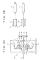
- FIG. 2A is a side view of one of the printing units employed in the offset press;
- FIG. 2B is a diagram showing different printing plates employed in the offset press;
- FIG. 3 is a perspective view showing the gapless printing plate employed in the offset press;
- FIG. 4 is an enlarged sectional view of the essential part of the gapless printing plate;
- FIG. 5 is a perspective view used to explain how the gapless printing plate is removed from or fitted on the plate cylinder of the press offset;
- FIG. 6 is a longitudinal sectional view of the plate cylinder employed in the offset press;
- FIG. 7 is a cross sectional view of the plate cylinder employed in the offset press;
- FIG. 8 is a schematic side view showing the essential part of an ordinary offset press; and
- FIG. 9 is an end view of the plate cylinder and the printing plate employed in the ordinary offset press.
-
- An offset press according to a preferred embodiment of the present invention will hereinafter be described in detail with reference to the drawings.
- In Fig. 1,
reference numeral 1 denotes a printing unit in the offset press andreference numeral 2 denotes a web. In this embodiment, eachprinting unit 1 is provided with a printer 1a and a regenerative side platemaker (referred to simply as a platemaker) 1b. The printer 1a is provided with upper andlower plate cylinders platemaker 1b may be provided for eachprinting unit 1, or a single platemaker may be provided for allprinting units 1. In the case where there is no need to discriminate between "upper" and "low," the plate cylinder and the blanket cylinder are represented byreference numerals - Each
plate cylinder 3 is equipped with aprinting plate 11, which has an image that is to be printed. Ink is supplied to theplate cylinder 3 by anink supply unit 21 shown in Fig. 2A. If ink is supplied to theplate cylinder 3, the image on theprinting plate 11 is transferred onto theblanket cylinder 4. The image transferred on theblanket cylinder 4 is printed on aweb 2 being traveled. - The
platemaker 1b is a device for deleting the image on theprinting plate 11 after printing and then writing a new image to theprinting plate 11. Thisplatemaker 1b is provided on the side (machine side) of the printer 1a. As shown in Fig. 1, theplatemaker 1b is equipped with aplate regenerator 31 for regenerating an image and aplate writer 32 for writing an image. - As shown in Fig. 3, the
printing plate 11 is constructed as a gapless printing plate. Thisgapless printing plate 11 is constructed of agapless sleeve 12. Thegapless sleeve 12 has a coating (lipophobic coating) and an organic compound coating (lipophilic coating) formed thereon, as described later. - The
blanket cylinder 4 has a gapless rubber plate (not shown) fitted thereon and is constructed as a gapless blanket cylinder. Because the gapless blanket cylinder is well known in the prior art, a description thereof will not be given. - The
sleeve 12 is formed from an elastically deformable material such as nickel and is formed into the shape of a cylinder open at both ends. The inside diameter of thesleeve 12 is slightly smaller than the outside diameter of theplate cylinder 3 on which thesleeve 12 is fitted. Therefore, when thesleeve 12 is fitted on theplate cylinder 3, theprinting plate 11 is fixed to theplate cylinder 3 by the friction force between thesleeve 12 and theplate cylinder 3. - As shown in Fig. 4, the
sleeve 12 has a coating (lipophobic coating) 13 of titanium dioxide (TiO2) formed thereon. Thetitanium dioxide coating 13 is formed by depositing a titanium dioxide photocatalyst on thenickel sleeve 12. Thetitanium dioxide coating 13 functions as non-printing portions to which no ink adheres, when irradiated with active titanium dioxide photocatalyst light. - The
titanium dioxide coating 13 can be formed by a chemical vapor deposition (CVD) method, a sputtering method, a sol-gel method, etc. However, the forming method is not limited to these methods. It is also possible to add the second material to thetitanium dioxide coating 13 to enhance the strength of thecoating 13, to enhance the adhesion between thecoating 13 and thesleeve 12, to enhance the activity of the photocatalyst, or to enhance the hydrophilic property and water retentivity of thecoating 13. Furthermore, an intervening layer may be provided between thenickel sleeve 12 and thetitanium dioxide coating 13 to enhance the adhesion therebetween. - If the
titanium dioxide coating 13 is irradiated with the aforementioned active light (i.e., ultraviolet light with a wavelength of 400 nm or less), thetitanium dioxide coating 13 will exhibit high lipophobic property (hydrophilic property) by action of the titanium dioxide photocatalyst. In this manner, the exposed portions are formed as non-printing portions to which ink does not adhere. In addition, if thetitanium dioxide coating 13 is irradiated with the active light, an organic compound on the photocatalyst surface can be resolved. - An organic compound coating (hydrophilic coating) 14 is formed on the
titanium dioxide coating 13. The surface of theorganic compound coating 14 exhibits a high hydrophilic property of repelling water but absorbing ink. The organic compound surface also has the property of being resolved by action of the titanium dioxide photocatalyst when irradiated with the aforementioned active light. - Now, a method of forming the
organic compound coating 14 will be described. An organic compound, which exhibits hydrophilic property when deposited on the surface of thetitanium dioxide coating 13, is dissolved or dispersed into a water or organic liquid. Then, the resultant liquid is deposited on the surface of thetitanium dioxide coating 13. In this manner theorganic compound coating 14 is formed. Note that after deposition, theorganic compound coating 14 may be dried as needed. - An image to be printed is written to the
organic compound coating 14 by theplate writer 32. Theplate writer 32 is equipped with a write head for irradiating infrared laser light. If infrared laser light is irradiated to theorganic compound coating 14, the exposed portions are heated and hardened, and stick fast to thetitanium dioxide coating 13. - Thereafter, the unexposed portions are cleaned and removed to develop the hydrophilic non-printing portions on the
titanium dioxide coating 13. In this way, an image consisting of printing portions and non-printing portions is formed on theprinting plate 11. - The portions not exposed to laser light may be removed by cleaning with a cleaning agent before the start of printing, or by ink tacks after the start of printing.
- The
plate writer 32 is also able to employ, for example, a write head capable of irradiating the aforementioned active light. If theorganic compound coating 14 is exposed to the active light, the exposed portions are dissolved and removed and the hydrophilic non-printing portions in thetitanium dioxide coating 13 are developed. In this manner, an image consisting of printing portions and non-printing portions is formed on theprinting plate 11. - After printing, the ink on the surface of the
printing plate 11 is removed with a washer (not shown). Next, theprinting plate 11 is irradiated with ultraviolet rays by an ultraviolet ray irradiating device (not shown) to dissolve and remove the printing portions consisting of an organic compound. At the same time, the surface of thetitanium dioxide coating 13 is caused to be hydrophilic. Next, by coating the surface of thetitanium dioxide coating 13 with an organic compound again, regeneration of theprinting plate 11 becomes possible. Note that the washer and the ultraviolet ray irradiating device constitute theplate regenerator 31. - While it has been described that the
coating 13 is formed by employing titanium dioxide, thecoating 13 may be formed by employing aluminum instead of titanium dioxide. In this case, thelipophilic coating 14 can be formed by depositing a photosensitive resin on thealuminum coating 13. - In the
platemaker 1b, a new image to be used in the next printing is written to theprinting plate 11 during operation of the printer 1a. If the writing of the new image is completed, theprinting plate 11 is moved to a predetermined position and waits for the next plate exchanging operation. - When an exchange of plates is performed, the printing plate (old plate) 11 is removed from the
plate cylinder 3 and taken in theplatemaker 1b. At nearly the same time, anew printing plate 11 is fitted on theplate cylinder 3. In this way, the time to exchange plates can be shortened. - When an exchange of plates is performed, as shown in Fig. 5, the
printing plate 11 is removed from or fitted on theplate cylinder 3 by being moved away from or toward theplate cylinder 3 in the axial direction of theplate cylinder 3. This is one of the major characteristics of the cylindrical printing plate (gapless printing plate) 11. This characteristic greatly enhances the operation efficiency of the plate exchange. - The outside diameter of the
plate cylinder 3 is slightly greater than the inside diameter of thesleeve 12. Therefore, by utilizing the elastic deformation of thesleeve 12, theprinting plate 11 can be fixed to theplate cylinder 3. In addition, as shown in Fig. 5, theplate cylinder 3 is formed into a tape shape in which oneend 301 is smaller in diameter than theother end 302. This facilitates the fitting of theprinting plate 11 onto theplate cylinder 3. - As shown in Fig. 6, the
plate cylinder 3 has acavity 33 interiorly. Thiscavity 33 is connected to an air pump or high-pressure fluid supply means (not shown) through anair supply passage 34, and air pressurized by this air pump is supplied to thecavity 33 through theair supply passage 34. - As shown in Figs. 6 and 7, a plurality of
air passages 35 are formed in the outer periphery of theplate cylinder 3 so that they are communicated with thecavity 33. Theseair passages 35 are provided over the entire length of theplate cylinder 3 at predetermined intervals in the axial direction of theplate cylinder 3, as shown in Fig. 6. Theair passages 35 are also arranged in a radial manner, as shown in Fig. 7. This arrangement makes it possible to inject high-pressure air evenly at approximately the entire periphery of theplate cylinder 3. Note that the aforementionedair supply passage 34 may be connected to either oneend 301 of theplate cylinder 3 or theother end 302. However, considering the operation efficiency of the plate exchange, theother end 302 of theplate cylinder 3 is preferred. - The
plate cylinder 3 is rotatably supported on the frame (not shown) of the printer 1a throughbearings 36. Oneend 301 of theplate cylinder 3 is detachably attached to the printer frame. The operation of exchanging theprinting plate 11 is performed with the oneend 301 of theplate cylinder 3 removed from the printer frame. - Therefore, when exchanging the
printing plate 11, rotation of theplate cylinder 3 is stopped and oneend 301 of theplate cylinder 3 is removed from the printer frame (not shown). Then, the air pump (not shown) is operated to supply high-pressure air to thecavity 33 of theplate cylinder 3 through theair supply passages 34. The high-pressure air acts over the entire periphery and entire length of theplate cylinder 3 through theair passages 35. - With action of the high-pressure air, the printing plate (old plate) 11 fitted on the
plate cylinder 3 is elastically deformed and the inside diameter increases slightly. This increase in the inside diameter creates a slight gap between the inner peripheral surface of theprinting plate 11 and the outer peripheral surface of theplate cylinder 3. In this state, the printing plate (old plate) 11 is removed by being pulled out from oneend 301 of theplate cylinder 3. - When fitting the printing plate (new plate) 11 on the
plate cylinder 3, theprinting plate 11 is fitted on oneend 301 of theplate cylinder 3 on which high-pressure air is acting. Since oneend 301 of theplate cylinder 3 is slightly smaller in diameter than theother end 302, theprinting plate 11 can be fitted on oneend 301 of theplate cylinder 3 without being elastically deformed. - If the
printing plate 11 is fitted on oneend 301 of theplate cylinder 3, theprinting plate 11 fitted on theplate cylinder 3 is elastically deformed by action ofthehigh-pressure air. Therefore, by gradually pushing theprinting plate 11 in the axial direction of theplate cylinder 3, it can be fitted on theplate cylinder 3. Next, the operation of the air pump is stopped, whereby theprinting plate 11 returns to its original shape and is fixed to theplate cylinder 3. That is, because of the friction force between theprinting plate 11 and theplate cylinder 3, theprinting plate 11 is fixed to theplate cylinder 3. - After the printing plate is fitted on the
plate cylinder 3 in the aforementioned manner, oneend 301 of theplate cylinder 3 is attached to the printer frame again and the plate exchanging operation ends. - The
platemaker 1b is arranged just beside theplate cylinder 3. As theplatemaker 1b is thus arranged, the removal of theold printing plate 11 from theplate cylinder 3 and the fitting of theold printing plate 11 onto theplatemaker 1b can be completed in a single operation by moving theold printing plate 11 with respect to theplate cylinder 3 in the axial direction of theplate cylinder 3. When fitting the printing plate (new plate) 11 on theplate cylinder 3, the removal of thenew printing plate 11 from theplate maker 1b and the fitting of thenew printing plate 11 onto theplate cylinder 3 can be similarly completed in a single operation by axially moving thenew printing plate 11 held in theplatemaker 1b. - The printer 1a, incidentally, is constructed as a cutoff printer capable of varying the circumferential length of the printing plate.
- Now, a brief description will be given of an ordinary offset press. In the offset press, the driving force from a single drive source is usually transmitted to the printing units through shafts (driving shafts). Each plate cylinder and each blanket cylinder are connected together through gears. These gears are driven by the driving force transmitted via the aforementioned shafts. In this way, rotations of the printing units are synchronized accurately with one another.
- In such a construction, however, the positions of the center axes of the plate cylinder and blanket cylinder cannot be changed because they are connected via gears. Because of this, the outside diameter of the printing plate is limited to one kind. On the other hand, webs are classified into two kinds of standards: an A-series and a B-series. For this reason, an ordinary offset press can adopt only either of the two standards for webs.
- On the other hand, in the printer 1a of the preferred embodiment, the circumferential length of the printing plate is variable so that printing can be performed on both the A-series web and the B-series web. That is, as shown in Fig. 2A, the
plate cylinder 3 and theblanket cylinder 4 are provided withmotors 41 as drive sources, respectively. Therefore, theplate cylinder 3 and theblanket cylinder 4 can be individually driven. Although details are not shown, theplate cylinder 3 and theblanket cylinder 4 are constructed so that they are each movable in the radial direction (vertical direction shown in Fig. 2) by ball-screw mechanisms, for example. - As shown in Fig. 2B, the
printing plate 11 in the preferred embodiment is provided with afirst printing plate 11a whose circumferential length corresponds to the A-series and asecond printing plate 11b whose circumferential length corresponds to the B-series. The first andsecond printing plates same plate cylinder 3. - Such a construction enables a single offset press to meet a plurality of standards for webs. For instance, in the case where the
second printing plate 11b for the B-series is used after printing is performed by thefirst printing plate 11a for the A-series, theplate cylinder 3 and theblanket cylinder 4 are moved to a predetermined position for the B-series before thesecond printing plate 11b is fitted on theplate cylinder 3. - If the
second printing plate 11b is fitted on theplate cylinder 3, theplate cylinder 3 and theblanket cylinder 4 are driven by therespective motors 41 and perform printing. Note that the speed of eachmotor 41 is controlled on the basis of a control signal from a controller (not shown). - The offset press of the preferred embodiment has the following advantages, because it is constructed as mentioned above:
- According to the offset press of the preferred embodiment, the
gapless printing plate 11 is employed in combination with theplatemaker 1b. Therefore, the offset press is capable of obtaining the synergetic effect between the advantage that the plate exchanging operation is easy and efficient and the advantage that theprinting plate 11 can be repeatedly used by theplatemaker 1b. Thus, the offset press of the present invention can achieve a substantial reduction in cost. - If the
printing plate 11 is moved in the axial direction of theplate cylinder 3, theprinting plate 11 can be removed from theplate cylinder 3 and fitted onto theplatemaker 1b, and in addition, it can be removed from theplatemaker 1b and fitted onto theplate cylinder 3. Thus, the removal of the printing plate (old plate) 11 from theplate cylinder 3 and the fitting of the printing plate (oldplate) 11 onto theplatemaker 1b can be completed in a single operation. Likewise, the removal of the printing plate (new plate) 11 from theplatemaker 1b and the fitting of the printing plate (new plate) 11 onto theplate cylinder 3 can be completed in a single operation. Thus, there is an advantage that the plate exchanging operation can be more efficiently performed. - The
plate cylinder 3 and the blanket cylinder (transfer cylinder) 4 are respectively provided with motors (drive sources) 41 and movable in the radial or vertical direction, so there is an advantage that the single offset press of the preferred embodiment can employ webs of different standards. Compared with the case where two offset presses are required, costs can be considerably reduced. In addition, a lot of space can be saved because only a place for installation of a single offset press is required. - During operation of the printer 1a, the
platemaker 1b writes a new image to a printing plate that is employed in the next printing. Therefore, the removal of an old printing plate and the fitting of a new printing plate can be continuously carried out. As a result, the time required for an exchange of plates can be considerably shortened. - A combination of the
gapless printing plate 11 and thegapless blanket cylinder 4 can eliminate a blank between prints, so there is an advantage that loss of paper can be eliminated. Furthermore, since thegapless printing plate 11 is formed by the elastically deformablegapless sleeve 12, theprinting plate 11 can be fixed to theplate cylinder 3 by friction force, and means for fixing theprinting plate 11 to theplate cylinder 3 becomes unnecessary. - In the conventional offset press, gaps (see
reference numeral 6 in Fig. 9) are present in theplate cylinder 3 and theblanket cylinder 4. Because of this, if theplate cylinder 3 and theblanket cylinder 4 make one revolution, the two gaps abut each other and therefore great load fluctuations take place in theplate cylinder 3 and theblanket cylinder 4. On the other hand, the offset press of the present invention has no gap in theplate cylinder 3 and theblanket cylinder 4 and is therefore able to eliminate such great load fluctuations. - The titanium dioxide coating (lipophobic coating) 13 forming non-printing portions is formed on the
sleeve 12, and the organic compound coating (hydrophilic coating) 14 forming printing portions is formed on the titanium dioxide coating (lipophobic coating) 13. With this arrangement, there is an advantage that regeneration and writing can be performed easily on theprinting plate 11. - The
sleeve 12 is formed from an elastic member (e.g., nickel). Therefore, by elastically deforming thesleeve 12 when fitting theprinting plate 11 on theplate cylinder 3, theprinting plate 11 can be fixed to theplate cylinder 3. That is, the outside diameter of theplate cylinder 3 is made slightly greater than the inside diameter of thesleeve 12. When fitting theprinting plate 11 on theplate cylinder 3, thesleeve 12 is elastically deformed so that the inside diameter thereof is increased. After the fitting of theprinting plate 11, thesleeve 12 is returned to its original shape. In this manner, theprinting plate 11 can be fixed to theplate cylinder 3. Because of this, there is no need to provide means for fixing theprinting plate 11 to theplate cylinder 3, and a reduction in the weight of theplate cylinder 3 can be achieved. In addition, by reducing the weight of theplate cylinder 3, the force of inertia of theplate cylinder 3 can be reduced during operation of the offset press and therefore there is an advantage that accuracy of rotation is enhanced. - The
plate cylinder 3 is tapered so that the diameter of oneend 301 becomes smaller than that of theother end 302. This facilitates the fitting of theprinting plate 11 onto theplate cylinder 3, so that there is an advantage that the operation efficiency of the plate exchange is further enhanced. - While the present invention has been described with reference to the preferred embodiment thereof, the invention is not to be limited to the details given herein, but may be modified within the scope of the invention hereinafter claimed. For example, while it has been described in the aforementioned embodiment that the
side platemaker 1b is provided for eachprinting unit 1, only a single (common) side platemaker may be provided for a plurality ofprinting units 1, as in the case of color printing. For example, twoside platemaker 1b may be provided for 8 printing units so that asingle side platemaker 1b is employed for 4 printing units. - In addition, in this case, the
side platemaker 1b may be arranged separately from the printing unit 1a and installed in a room under the control of temperature and humidity. After the printing plate needed to be exchanged is removed from the printing unit 1a, the printing plate may be fitted on theside platemaker 1b. - Furthermore, the
side platemaker 1b may be provided near theprinting unit 1 so that it is movable, and theside platemaker 1b may be moved sequentially to the printing plates needed to be exchanged. - In these cases, if an exchange of printing plates is executed at each
printing unit 1, and the old printing plates are removed, then new patterns are written sequentially to the old printing plates by the side platemaker during the time that printing is performed using new printing plates. - In these cases, an exchange of printing plates and reproduction cannot be carried out at the same time, as is done in the aforementioned embodiment. However, a reduction in installation costs and a saving in space can be achieved, and in addition, the number of troublesome maintenance operations can be reduced.
- Moreover, among all the printing plates, a predetermined number of printing plates may be made as one set, and side plate makers may be provided to the printing plates of the one set, respectively. That is, according to user needs (user needs of whether priority is given to a reduction in the time of the plate exchange and the reproducing operation, or user needs of whether priority is given to a reduction in installation costs and a saving in space), the number of installed side platemakers with respect to a printing plate can be appropriately determined.
- In addition, the inside diameter of the
sleeve 12 can be made slightly greater than the outside diameter of theplate cylinder 3. In this case, an exchange of plates becomes simpler and therefore the operation efficiency is considerably enhanced. In this case, means for fixing theprinting plate 11 to theplate cylinder 3 becomes necessary. However, theprinting plate 11 can be easily fixed to theplate cylinder 3 by generating negative pressure within thecavity 33 shown in Figs. 6 and 7. - While it has been described that high-pressure air is supplied by the air pump (high-pressure fluid supply means), other fluids may be employed. The number and position of
air passages 35 may be changed as long as they do not interfere with the plate exchanging operation.
Claims (9)
- An offset press comprising:wherein said printing plate (11) is constructed of a gapless printing plate.a printer (1a) comprising
a plate cylinder (3) on which a printing plate (11) is fitted, and
a transfer cylinder (4) to which an image on said printing plate (11) is transferred; anda regenerative platemaker (1b), arranged near said printer (1a), for writing said image to said printing plate (11); - The offset press as set forth in claim 1, wherein said regenerative platemaker (1b) is arranged beside said printer (1a) so that said printing plate (11) can be removed from and fitted on said plate cylinder (3) and fitted on and removed from said regenerative platemaker (1b) by being moved along an axial direction of said plate cylinder (3).
- The offset press as set forth in claim 1, wherein said printer (1a) comprises a plurality of printers (1a), and a single regenerative side platemaker (1b) is provided for said plurality of printers (1a).
- The offset press as set forth in any one of claims 1 through 3, wherein said plate cylinder (3) and said transfer cylinder (4) are constructed so that they are respectively provided with drive sources and movable in a radial direction.
- The offset press as set forth in claim 2, wherein said regenerative platemaker (1b) is constructed so that during operation of said printer (1a), it writes a new image to said printing plate (11) that is employed in the next printing.
- The offset press as set forth in any one of claims 1 through 5, wherein said transfer cylinder (4) comprises a gapless transfer cylinder.
- The offset press as set forth in any one of claims 1 through 6, wherein said gapless printing plate (11) comprises
a radially deformable gapless sleeve (12),
a lipophobic coating (13), formed on said sleeve (12), which forms non-printing portions of said image, and
a lipophilic coating (14), formed on said lipophobic coating (13), which forms printing portions of said image. - The offset press as set forth in claim 7, wherein
said sleeve (12) is formed from nickel, and
said lipophobic coating (13) is formed by depositing aluminum or titanium dioxide on said sleeve (12). - The offset press as set forth in claim 8, wherein said lipophilic coating (14) is formed by depositing an organic compound or photosensitive resin on said lipophobic coating (13).
Applications Claiming Priority (4)
| Application Number | Priority Date | Filing Date | Title |
|---|---|---|---|
| JP2001180715 | 2001-06-14 | ||
| JP2001180714 | 2001-06-14 | ||
| JP2001180714 | 2001-06-14 | ||
| JP2001180715A JP2002370466A (en) | 2001-06-14 | 2001-06-14 | Press plate without gap and offset printer |
Publications (1)
| Publication Number | Publication Date |
|---|---|
| EP1266752A1 true EP1266752A1 (en) | 2002-12-18 |
Family
ID=26616932
Family Applications (1)
| Application Number | Title | Priority Date | Filing Date |
|---|---|---|---|
| EP02012489A Withdrawn EP1266752A1 (en) | 2001-06-14 | 2002-06-12 | Offset press |
Country Status (3)
| Country | Link |
|---|---|
| US (1) | US20020189478A1 (en) |
| EP (1) | EP1266752A1 (en) |
| CN (1) | CN1392048A (en) |
Cited By (1)
| Publication number | Priority date | Publication date | Assignee | Title |
|---|---|---|---|---|
| DE102006032204B3 (en) * | 2006-07-12 | 2007-10-31 | Koenig & Bauer Aktiengesellschaft | Printing block supplying method for use in e.g. sheet offset printing press, involves supporting movement of printing block and mounting of block at mounting place by rolling unit integrated in transport module |
Families Citing this family (2)
| Publication number | Priority date | Publication date | Assignee | Title |
|---|---|---|---|---|
| US20080072777A1 (en) * | 2004-12-10 | 2008-03-27 | Torao Iwamoto | Rotary Press |
| CN109963716B (en) | 2016-10-18 | 2020-12-11 | 旭化成株式会社 | printing device |
Citations (4)
| Publication number | Priority date | Publication date | Assignee | Title |
|---|---|---|---|---|
| US4913048A (en) * | 1985-12-11 | 1990-04-03 | Tittgemeyer Engineering | Method and apparatus for printing with a lithographic sleeve |
| US5419255A (en) * | 1992-04-21 | 1995-05-30 | Albert-Frankenthal Aktiengesellschaft | Device for forming a printing pattern on a printing sleeve |
| US5674658A (en) * | 1994-06-16 | 1997-10-07 | Eastman Kodak Company | Lithographic printing plates utilizing an oleophilic imaging layer |
| DE19805898A1 (en) * | 1998-02-13 | 1999-11-04 | Roland Man Druckmasch | Printing unit for a web-fed rotary printing press |
Family Cites Families (15)
| Publication number | Priority date | Publication date | Assignee | Title |
|---|---|---|---|---|
| US4144812A (en) * | 1975-01-08 | 1979-03-20 | Strachan & Henshaw Limited | Printing sleeves |
| US4718340A (en) * | 1982-08-09 | 1988-01-12 | Milliken Research Corporation | Printing method |
| US5129321A (en) * | 1991-07-08 | 1992-07-14 | Rockwell International Corporation | Direct-to-press imaging system for use in lithographic printing |
| DE4309658C1 (en) * | 1993-03-25 | 1994-10-27 | Roland Man Druckmasch | Device for automatically changing printing plates in sheet-fed offset printing machines with several printing units |
| US5802975A (en) * | 1993-12-03 | 1998-09-08 | Man Roland Druckmaschinen Ag | Device for manipulating sleeves on cylinders |
| US5440987A (en) * | 1994-01-21 | 1995-08-15 | Presstek, Inc. | Laser imaged seamless lithographic printing members and method of making |
| US5813336A (en) * | 1995-12-22 | 1998-09-29 | Heidelberger Druckmaschinen Ag | Printing unit with axially removable printing sleeves |
| US6374731B1 (en) * | 1997-04-18 | 2002-04-23 | Heidelberger Druckmaschinen Ag | Lithographic newspaper printing press |
| DE69805723T2 (en) * | 1997-09-12 | 2003-01-02 | Fuji Photo Film Co., Ltd. | Planographic printing and printing plate precursor for planographic printing |
| JP2000098831A (en) * | 1998-09-21 | 2000-04-07 | Mitsubishi Heavy Ind Ltd | Method for regenerating printing plate material and printing machine |
| US6186068B1 (en) * | 1999-05-18 | 2001-02-13 | Creo Srl | Method for holding printing sleeves in an imaging device |
| US6487970B2 (en) * | 2000-01-18 | 2002-12-03 | Agfa-Gevaert | Method of lithographic printing with a reusable substrate |
| DE10021451A1 (en) * | 2000-05-03 | 2001-11-08 | Heidelberger Druckmasch Ag | Controlled imaging and deletion of a printing form made of metallic titanium |
| JP3407112B2 (en) * | 2000-10-30 | 2003-05-19 | 株式会社東京機械製作所 | Plate mounting position determination device |
| US6748864B2 (en) * | 2000-11-14 | 2004-06-15 | Agfa-Gevaert | Apparatus for automatic plate coating and cleaning |
-
2002
- 2002-06-07 US US10/163,412 patent/US20020189478A1/en not_active Abandoned
- 2002-06-12 EP EP02012489A patent/EP1266752A1/en not_active Withdrawn
- 2002-06-13 CN CN02122798A patent/CN1392048A/en active Pending
Patent Citations (4)
| Publication number | Priority date | Publication date | Assignee | Title |
|---|---|---|---|---|
| US4913048A (en) * | 1985-12-11 | 1990-04-03 | Tittgemeyer Engineering | Method and apparatus for printing with a lithographic sleeve |
| US5419255A (en) * | 1992-04-21 | 1995-05-30 | Albert-Frankenthal Aktiengesellschaft | Device for forming a printing pattern on a printing sleeve |
| US5674658A (en) * | 1994-06-16 | 1997-10-07 | Eastman Kodak Company | Lithographic printing plates utilizing an oleophilic imaging layer |
| DE19805898A1 (en) * | 1998-02-13 | 1999-11-04 | Roland Man Druckmasch | Printing unit for a web-fed rotary printing press |
Cited By (1)
| Publication number | Priority date | Publication date | Assignee | Title |
|---|---|---|---|---|
| DE102006032204B3 (en) * | 2006-07-12 | 2007-10-31 | Koenig & Bauer Aktiengesellschaft | Printing block supplying method for use in e.g. sheet offset printing press, involves supporting movement of printing block and mounting of block at mounting place by rolling unit integrated in transport module |
Also Published As
| Publication number | Publication date |
|---|---|
| US20020189478A1 (en) | 2002-12-19 |
| CN1392048A (en) | 2003-01-22 |
Similar Documents
| Publication | Publication Date | Title |
|---|---|---|
| US8256346B2 (en) | Plateless lithographic printing | |
| US6101944A (en) | Method for operating a rotary printing press and device for carrying out the method | |
| US6895861B2 (en) | Keyless inking systems and methods using subtractive and clean-up rollers | |
| JP2002370341A (en) | Printer having inking unit with caster | |
| EP1266754A1 (en) | Offset press and gapless printing plate | |
| AU2327399A (en) | Retractable cleaning system for lithographic printing plates | |
| US20020189478A1 (en) | Offset press | |
| JP2004074526A (en) | Sleeve for plate cylinder | |
| EP1277577A1 (en) | Imprinter apparatus | |
| US20010037741A1 (en) | Print unit in a printing press | |
| US6782824B2 (en) | Printing unit with reversible image setting and digital changeover | |
| JP2000117941A (en) | Method and apparatus for exchange of flying type form plate | |
| JP3759011B2 (en) | Plate making press | |
| JP2002370466A (en) | Press plate without gap and offset printer | |
| JP2003062967A (en) | Offset printing machine | |
| US20070101883A1 (en) | Printing system using shape-changing materials | |
| JP3338335B2 (en) | Web offset press | |
| JP3524862B2 (en) | Switching type continuous printing press | |
| US8807029B2 (en) | Plateless lithographic printing | |
| JP2003001790A (en) | Offset press | |
| US6543361B2 (en) | Method of increasing the service life of printing forms whereon images can be set in printing machines | |
| JP2004223995A (en) | Printing system | |
| JP3700963B2 (en) | Development processing apparatus in printing apparatus | |
| JP2001293853A (en) | Image forming apparatus and method | |
| JP2000127333A (en) | Printing device and plate drum device |
Legal Events
| Date | Code | Title | Description |
|---|---|---|---|
| PUAI | Public reference made under article 153(3) epc to a published international application that has entered the european phase |
Free format text: ORIGINAL CODE: 0009012 |
|
| AK | Designated contracting states |
Kind code of ref document: A1 Designated state(s): AT BE CH CY DE DK ES FI FR GB GR IE IT LI LU MC NL PT SE TR |
|
| AX | Request for extension of the european patent |
Free format text: AL;LT;LV;MK;RO;SI |
|
| 17P | Request for examination filed |
Effective date: 20030207 |
|
| AKX | Designation fees paid |
Designated state(s): DE FR GB |
|
| STAA | Information on the status of an ep patent application or granted ep patent |
Free format text: STATUS: THE APPLICATION IS DEEMED TO BE WITHDRAWN |
|
| 18D | Application deemed to be withdrawn |
Effective date: 20060905 |