EP1266501B1 - A silencer for an air flow generator - Google Patents
A silencer for an air flow generator Download PDFInfo
- Publication number
- EP1266501B1 EP1266501B1 EP01915117A EP01915117A EP1266501B1 EP 1266501 B1 EP1266501 B1 EP 1266501B1 EP 01915117 A EP01915117 A EP 01915117A EP 01915117 A EP01915117 A EP 01915117A EP 1266501 B1 EP1266501 B1 EP 1266501B1
- Authority
- EP
- European Patent Office
- Prior art keywords
- air
- silencer
- flow
- channel
- housing
- Prior art date
- Legal status (The legal status is an assumption and is not a legal conclusion. Google has not performed a legal analysis and makes no representation as to the accuracy of the status listed.)
- Expired - Lifetime
Links
- 230000003584 silencer Effects 0.000 title claims abstract description 34
- 238000005452 bending Methods 0.000 claims abstract description 8
- 230000001603 reducing effect Effects 0.000 claims abstract description 7
- 238000011144 upstream manufacturing Methods 0.000 claims description 2
- 238000004519 manufacturing process Methods 0.000 abstract description 6
- 230000001743 silencing effect Effects 0.000 abstract description 3
- 239000000243 solution Substances 0.000 description 4
- 238000013016 damping Methods 0.000 description 3
- 230000000694 effects Effects 0.000 description 3
- 230000010355 oscillation Effects 0.000 description 3
- 239000011358 absorbing material Substances 0.000 description 2
- 239000006261 foam material Substances 0.000 description 2
- 230000030279 gene silencing Effects 0.000 description 2
- 238000001746 injection moulding Methods 0.000 description 2
- 239000000463 material Substances 0.000 description 2
- 239000004033 plastic Substances 0.000 description 2
- 229920003023 plastic Polymers 0.000 description 2
- 238000010521 absorption reaction Methods 0.000 description 1
- 230000005540 biological transmission Effects 0.000 description 1
- 238000004891 communication Methods 0.000 description 1
- 238000001816 cooling Methods 0.000 description 1
- 238000010141 design making Methods 0.000 description 1
- 230000003467 diminishing effect Effects 0.000 description 1
- 230000001747 exhibiting effect Effects 0.000 description 1
- 238000009434 installation Methods 0.000 description 1
- 239000012774 insulation material Substances 0.000 description 1
- 230000002452 interceptive effect Effects 0.000 description 1
- 238000000034 method Methods 0.000 description 1
- 239000002245 particle Substances 0.000 description 1
Images



Classifications
-
- A—HUMAN NECESSITIES
- A47—FURNITURE; DOMESTIC ARTICLES OR APPLIANCES; COFFEE MILLS; SPICE MILLS; SUCTION CLEANERS IN GENERAL
- A47L—DOMESTIC WASHING OR CLEANING; SUCTION CLEANERS IN GENERAL
- A47L9/00—Details or accessories of suction cleaners, e.g. mechanical means for controlling the suction or for effecting pulsating action; Storing devices specially adapted to suction cleaners or parts thereof; Carrying-vehicles specially adapted for suction cleaners
- A47L9/0081—Means for exhaust-air diffusion; Means for sound or vibration damping
Definitions
- the present invention relates to a silencer according to the preamble of claim 1, comprising a motor housing that delimits a volume which extends at least radially around the air flow generator, said housing having a wall member extending in a generally axial direction and that is provided with at least one air inlet flow passage and at least one air outlet flow passage.
- the invention further relates to a method of reducing noise emission according to the preamble of claim 10.
- WO-A-97/13443 discloses a silencer for a vacuum cleaner of the above mentioned kind where the air flow generator is enclosed in a housing with an air inlet and an air outlet.
- the housing and the outlet is provided with sound absorbing foamed plastics material.
- EP-A-0 099 466 Another solution to the noise reduction problem is known from EP-A-0 099 466, in which a vacuum cleaner is disclosed.
- This vacuum cleaner is provided with sound absorbing foam material around the motor housing and around the inlet and outlet passages that are lined with sound absorbing material.
- the outlet passages in this vacuum cleaner are designed with several changes in cross-section areas and with bends in order to provide changes in the acoustical properties that lead to reflections of the noise.
- the vacuum cleaner is moreover with a damper in front of the air inlet.
- a silencer according to the initially mentioned kind, wherein at least one of said flow passages includes at least one folded elongated flow channel that is integrally formed in the wall member of the motor housing.
- the noise emission from air flow generators can be controlled by creating a relatively large volume around the air flow generator where this volume communicates with the outside through a long slim air flow channel.
- This principle of noise reduction is obtained by applying the principle of a Helmholz resonator.
- the system acts as a damping system where the air of the volume acts as a spring and the air in the channel as a mass.
- the length and cross-section area of the channel and the size of the volume of the housing can be chosen in accordance with the actual noise reduction requirements.
- noise at frequencies somewhat above the resonance frequency of the system is reduced without the use of sound absorbing foam material. It is no longer advantageous to reduce the volume of the motor housing in order to have a closely fitting sound absorption and/or to fill it with sound absorbing materials.
- the resonance frequency of the system is lowered by providing a relatively large volume of the housing comprising a relatively long and narrow channel.
- a plane wave condition is of preference.
- the plane wave condition can be obtained in the channel by the provision of ribs that are dividing the channel into a plurality of channels with smaller cross section dimensions.
- the invention contrary to the designs of the prior art silencers it is of preference to provide the channels with substantially the same opening through the system in order to keep the air velocity constant and hence the pressure loss low.
- a relatively long and compact channel is provided compared to the volume of the housing.
- This allows for a compact design of the silencer by integrating it into the motor housing. This in turn means that a compact design of the appliance in which the silencer is to be used can be obtained; just as an efficient means of noise reduction is obtainable having the same or even a superior silencing effect compared to the silencers known in the art.
- a silencer according to the invention a relatively simple structure is obtained that is easy and inexpensive to manufacture.
- the elongated flow channel exhibits successive duct portions with altering flow directions, and air flow bending portions between said portions. This allows for a particular compact arrangement of the channel in the wall member and a compact design of the housing.
- the successive duct portions have a gradual increase in radial position in the motor housing.
- a particular long yet compact channel is created by arranging the duct portions in annular or semi-annular configurations outside each other.
- the air flow bending portions is a 180° bend including an end wall that is generally orthogonal to the flow directions of two successive duct portions and that a connecting passage is provided between the two successive duct portions.
- a further noise reducing effect is obtained, since a wave of noise coming towards the end wall of the bend is reflected back into the duct portion. This can produce an interfering wave diminishing the noise transmitted into the successive duct portion.
- the height of the opening passage in the bend is four times the wave length of the sound wave in the duct, this additional noise reducing effect is particularly significant.
- sharp bends in air flow passages do not necessarily result in a noise increase and pressure loss providing that the air velocity is kept low.
- the wall member of the motor housing comprises a number of concentric shells with annular or semi-annular interior spaces between said shells defining the ducts.
- a particularly simple design of the housing is provided which is easy and inexpensive to manufacture since all the components can be produced by injection moulding.
- each of the duct portions is having an annular-shaped cross-section.
- the housing can be formed by the use of concentric cylindrical wall member components that can easily be produced e.g. in a plastic material by injection moulding.
- the at least one flow channel constitutes the air outlet flow passage of the housing.
- the silencer is required at the outlet.
- the invention could be used for other purposes such as a hair dryer, a cooker hood or other appliances making use of air flow generation.
- the air outlet flow passage is provided with a filter upstream the flow channel at the beginning of the outlet passage.
- a filter upstream the flow channel at the beginning of the outlet passage.
- the principle of a Helmholz resonator is used for silencing an air flow generator consisting of a motor with a blower in a vacuum cleaner.
- the housing 1 defines a volume V around the air flow generator 2.
- the air flow generator comprises a motor 2a and a blower 2b.
- An air inlet 4 and an air outlet 3 is provided in the housing.
- utility air such as air for cooling the motor, is sucked in through the inlet and through the air flow generator 2 and into the volume V.
- This constant air flow of a relatively high speed creates noise in the housing volume V.
- the air inside the volume V acts as a spring and the volume of air M in the channel 3 acts as a mass in the damper system.
- the air flow generator oscillates the air in the channel 3 via the volume V.
- the oscillations of the air flow generator and those of the air in the channel will be the same.
- the resonance frequency the oscillations of the air in the channel will be profoundly enhanced.
- the oscillations of the air in the channel 3 will be much less than those of the air flow generator.
- this silencing principle is adapted for use as a silencer in a vacuum cleaner, such as shown in a principle view in fig. 3.
- the channel 3 is bend or folded around the wall of the housing 1 whereby the same effect is obtained with regard to the long, narrow channel 3.
- the channel or channels 3 comprise a successive duct portions 3a and 3b that communicates with each other through a bend portion 3c of the channel(s) 3. In the bend 3c, the flow direction is reversed.
- the duct portions 3a, 3b are created by providing the housing 1 with a wall member having a multiple wall structure with wall sections 1a, 1b, 1c and an end wall section 1d.
- the wall structure of the housing 1 is made of cylindrical shells 1a, 1b, 1c that are different in diameter and arranged concentric around the air flow generator 2.
- FIG 4 is shown an air flow generator installation for a vacuum cleaner having a silencer according to the invention.
- the channel 3 is formed in the wall structure 1a, 1b, 1c of the housing 1.
- the channel 3 has in this embodiment a serpentine-like shape in a radial cross section view.
- the channel 3 in this embodiment is formed by three concentric shells 1a, 1b, 1c defining the interior duct passages 3a and 3b.
- the shells 1a-1c are formed in such a way that flow communication passages at the bends 3c are formed.
- the duct portions 3a and 3b are in this embodiment annular in shape with an increase in diameter for each subsequent duct portion 3b. In the embodiment shown, three shells are present whereby two duct portions are created. however, if appropriate any number of shells can be used, e.g. to provide a longer channel.
- the channel 3 should be as narrow as possible. However, it is realised that the velocity of the air flow in the duct portions must not be increased too much, as this would create noise in itself. Furthermore, the capacity of the channel 3 must sufficient for the required amount of air to flow through.
- the air is sucked into the air flow generator 2 through the air intake 4.
- the air flows through the air flow generator 2 and from there through a filter 6 and into another part of the volume V; and from there out through the silencer including the outlet channel 3.
- the duct portions 3a, 3b are not annular in shape but rather semi-circular. More general, it is by the invention realised that several designs of the outlet channel geometry can be created without departing from the scope of the invention as defined in the accompanying claims.
Landscapes
- Engineering & Computer Science (AREA)
- Mechanical Engineering (AREA)
- Duct Arrangements (AREA)
- Exhaust Silencers (AREA)
- Soundproofing, Sound Blocking, And Sound Damping (AREA)
- Motor Or Generator Cooling System (AREA)
- Exhaust Gas After Treatment (AREA)
- Feeding, Discharge, Calcimining, Fusing, And Gas-Generation Devices (AREA)
- Structures Of Non-Positive Displacement Pumps (AREA)
- Electric Suction Cleaners (AREA)
Abstract
Description
- fig. 1
- shows a schematical, principle view explaining the general principle of the noise reduction in a silencer according to the invention by applying the principle of a Helmholz resonator
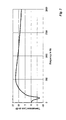
- fig. 2
- is a graphic representation of the noise reduction characteristics of such resonator,
- fig. 3
- is a schematic representation of a silencer according to the invention, and
- fig. 3a
- is a detail thereof, and
- fig. 4
- is a cross section view of an embodiment of a silencer according to the invention.
Claims (9)
- A silencer for reducing noise emission from an air flow generator (2) comprising a motor operating a blower, said silencer comprising a motor housing (1) that delimits a volume (V) which extends at least radially around the air flow generator (2), said housing (1) having a wall structure (1a-1d) extending in a generally axial direction and that is provided with at least one air inlet flow passage (4) and at least one air outlet flow passage (3), at least one of said flow passages includes at least one bend, elongated flow channel (3) that is integrally formed in the wall structure (1a, 1b, 1c) of the motor housing (1) and exhibits successive duct portions (3a, 3b) with altering flow directions, and air flow bending portions (3c) between said portions (3a, 3b),
characterised in that
the air flow bending portions (3c) include an end wall (1d) having non-sound-absorbing properties. - A silencer according to claim 1, wherein the successive duct portions (3a, 3b) have a gradual increase in radial position in the motor housing (1).
- A silencer according to claim 2, wherein the air flow bending portions are a 180° bend including an end wall (1d) that is generally orthogonal to the flow directions (I, T) of two successive duct portions (3a, 3b) and wherein a connecting passage (3c) is provided between the two successive duct portions (3a, 3b).
- A silencer according to any one of the preceding claims, wherein the cross-sectional opening of the elongated flow channel (3) is substantially the same through the system so as to keep the air velocity constant.
- A silencer according to any one of the preceding claims, wherein the wall structure (1a, 1b, 1c, 1d) of the motor housing (1) comprises a number of concentric shells comprising a plurality of ribs oriented in the flow direction.
- A silencer according to any one of the preceding claims, wherein each of the duct portions (3a, 3b) is having an annular-shaped cross-section.
- A silencer according to claim 1 to 5, wherein at least some of the duct portions (3a, 3b) are successively arranged in an annular configuration.
- A silencer according to any one of the preceding claims, wherein the at least one flow channel (3) constitutes the air outlet flow passage of the housing (1).
- A silencer according to claim 8, wherein the air outlet flow passage (3) is provided with a filter (6) upstream the flow channel (3).
Applications Claiming Priority (3)
| Application Number | Priority Date | Filing Date | Title |
|---|---|---|---|
| DK200000509 | 2000-03-24 | ||
| DKPA200000509 | 2000-03-24 | ||
| PCT/DK2001/000201 WO2001074025A1 (en) | 2000-03-24 | 2001-03-23 | A silencer for an air flow generator |
Publications (2)
| Publication Number | Publication Date |
|---|---|
| EP1266501A1 EP1266501A1 (en) | 2002-12-18 |
| EP1266501B1 true EP1266501B1 (en) | 2004-09-01 |
Family
ID=8159379
Family Applications (1)
| Application Number | Title | Priority Date | Filing Date |
|---|---|---|---|
| EP01915117A Expired - Lifetime EP1266501B1 (en) | 2000-03-24 | 2001-03-23 | A silencer for an air flow generator |
Country Status (7)
| Country | Link |
|---|---|
| EP (1) | EP1266501B1 (en) |
| AT (1) | ATE275311T1 (en) |
| AU (2) | AU2001242317B2 (en) |
| DE (1) | DE60105272T2 (en) |
| DK (1) | DK1266501T3 (en) |
| ES (1) | ES2227159T3 (en) |
| WO (1) | WO2001074025A1 (en) |
Cited By (2)
| Publication number | Priority date | Publication date | Assignee | Title |
|---|---|---|---|---|
| WO2014005586A1 (en) | 2012-07-04 | 2014-01-09 | Nilfisk-Advance A/S | A silencer system for a vacuum motor in a suction cleaner |
| EP4088636B1 (en) * | 2015-12-04 | 2024-03-20 | Aktiebolaget Electrolux | A vacuum cleaner |
Families Citing this family (9)
| Publication number | Priority date | Publication date | Assignee | Title |
|---|---|---|---|---|
| US7475449B2 (en) * | 2003-12-24 | 2009-01-13 | Daewoo Electronics Corporation | Vacuum cleaner |
| KR100555205B1 (en) * | 2003-12-31 | 2006-03-03 | 삼성광주전자 주식회사 | Vacuum cleaner |
| US7721384B2 (en) | 2005-08-25 | 2010-05-25 | Shop-Vac Corporation | Pneumatic cleaner |
| FR3046046B1 (en) | 2015-12-23 | 2017-12-22 | Seb Sa | GEOMETRY OF AERAULIC CIRCUIT FOR A HAND VACUUM |
| US10309302B2 (en) | 2016-03-09 | 2019-06-04 | Kohler Co. | Noise suppression system |
| DE102017206360B4 (en) * | 2017-04-13 | 2022-05-19 | Conti Temic Microelectronic Gmbh | Housing for a pneumatic control unit and pneumatic control unit |
| DE102018126736A1 (en) * | 2018-10-26 | 2020-04-30 | Miele & Cie. Kg | Blower capsule device for reducing noise for a blower, blower system with a blower capsule device, and method for manufacturing a blower system |
| EP4233660A1 (en) * | 2022-02-23 | 2023-08-30 | Versuni Holding B.V. | Noise reduction in a vacuum cleaner unit |
| WO2024188437A1 (en) | 2023-03-10 | 2024-09-19 | Versuni Holding B.V. | Noise reduction in a vacuum cleaner unit |
Family Cites Families (9)
| Publication number | Priority date | Publication date | Assignee | Title |
|---|---|---|---|---|
| DE7514249U (en) * | 1975-05-02 | 1976-04-08 | Siemens Ag, 1000 Berlin Und 8000 Muenchen | Soundproof device for vacuum cleaners |
| JPS5235475A (en) * | 1975-09-16 | 1977-03-18 | Tokyo Electric Co Ltd | Electric cleaner |
| US4280245A (en) * | 1980-02-19 | 1981-07-28 | Shop-Vac Corporation | Sound dome for electric vacuum cleaner |
| DE3225258C2 (en) * | 1982-07-06 | 1985-11-28 | Guido Oberdorfer Wap-Maschinen, 7919 Bellenberg | Vacuum cleaner |
| DE3904392A1 (en) * | 1989-02-14 | 1990-08-16 | Mauz & Pfeiffer Progress | VACUUM CLEANER |
| JPH0549561A (en) * | 1991-08-22 | 1993-03-02 | Matsushita Electric Ind Co Ltd | Cleaner |
| US5353469A (en) * | 1992-07-01 | 1994-10-11 | National Super Service Company | Wet/dry vacuum cleaner with noise reducing housing structure |
| AU707268B2 (en) * | 1995-10-10 | 1999-07-08 | Nilfisk A/S | A silencer for a suction cleaner |
| KR100190684B1 (en) * | 1996-05-17 | 1999-06-01 | 전주범 | Muffler chamber system of vacuum cleaner |
-
2001
- 2001-03-23 ES ES01915117T patent/ES2227159T3/en not_active Expired - Lifetime
- 2001-03-23 EP EP01915117A patent/EP1266501B1/en not_active Expired - Lifetime
- 2001-03-23 DE DE60105272T patent/DE60105272T2/en not_active Expired - Lifetime
- 2001-03-23 DK DK01915117T patent/DK1266501T3/en active
- 2001-03-23 AU AU2001242317A patent/AU2001242317B2/en not_active Ceased
- 2001-03-23 AT AT01915117T patent/ATE275311T1/en not_active IP Right Cessation
- 2001-03-23 AU AU4231701A patent/AU4231701A/en active Pending
- 2001-03-23 WO PCT/DK2001/000201 patent/WO2001074025A1/en not_active Ceased
Cited By (2)
| Publication number | Priority date | Publication date | Assignee | Title |
|---|---|---|---|---|
| WO2014005586A1 (en) | 2012-07-04 | 2014-01-09 | Nilfisk-Advance A/S | A silencer system for a vacuum motor in a suction cleaner |
| EP4088636B1 (en) * | 2015-12-04 | 2024-03-20 | Aktiebolaget Electrolux | A vacuum cleaner |
Also Published As
| Publication number | Publication date |
|---|---|
| AU2001242317B2 (en) | 2004-11-11 |
| WO2001074025A1 (en) | 2001-10-04 |
| DE60105272T2 (en) | 2005-09-15 |
| DE60105272D1 (en) | 2004-10-07 |
| ES2227159T3 (en) | 2005-04-01 |
| AU4231701A (en) | 2001-10-08 |
| ATE275311T1 (en) | 2004-09-15 |
| WO2001074025A9 (en) | 2001-12-20 |
| DK1266501T3 (en) | 2004-09-20 |
| EP1266501A1 (en) | 2002-12-18 |
Similar Documents
| Publication | Publication Date | Title |
|---|---|---|
| US5924456A (en) | Tubular section member, in particular for use as a fluid flow duct | |
| US4433751A (en) | Sound suppressor liner | |
| US6094774A (en) | Silencer for a suction cleaner | |
| US4596921A (en) | Low noise hand-held hairdryer | |
| AU2001242317B2 (en) | A silencer for an air flow generator | |
| US4782912A (en) | Engine air cleaner - noise reducer | |
| EP0859906B1 (en) | A noise attenuator for an induction system or an exhaust system | |
| US6520284B2 (en) | Air intake device comprising a duct section provided with openings | |
| US6415887B1 (en) | Refractive wave muffler | |
| AU2001242317A1 (en) | A silencer for an air flow generator | |
| JPH06207563A (en) | Exhaust turbo-supercharger | |
| JPH04506850A (en) | Series noise attenuator for gas pipes | |
| US7337876B2 (en) | Suction apparatus with noise reduction means | |
| WO2019011313A1 (en) | Vacuum cleaner and motor module thereof | |
| US20080023265A1 (en) | Combination Silencer | |
| US20200224898A1 (en) | Flow generation unit, air treatment plant comprising said flow generation unit and use of the latter for air treatment | |
| RU2415635C2 (en) | Vacuum cleaner equipped with noise reduction device | |
| CN116157602B (en) | Tubular fan designed as radial fan | |
| CN112460071A (en) | Noise-reduction volute tongue, volute, fan and range hood | |
| US12448987B2 (en) | Noise reduction for air flow devices | |
| CN222531440U (en) | Silencers, silencers and cleaning equipment for electric motors | |
| JPH1173189A (en) | Silencer and silencer | |
| CN220124610U (en) | Noise reduction device and dust collector | |
| CN209569049U (en) | Rear muffler and internal combustion engine exhaust system | |
| CN115539410A (en) | Centrifugal fan and air conditioner |
Legal Events
| Date | Code | Title | Description |
|---|---|---|---|
| PUAI | Public reference made under article 153(3) epc to a published international application that has entered the european phase |
Free format text: ORIGINAL CODE: 0009012 |
|
| 17P | Request for examination filed |
Effective date: 20020913 |
|
| AK | Designated contracting states |
Kind code of ref document: A1 Designated state(s): AT BE CH CY DE DK ES FI FR GB GR IE IT LI LU MC NL PT SE TR |
|
| AX | Request for extension of the european patent |
Free format text: AL;LT;LV;MK;RO;SI |
|
| RIN1 | Information on inventor provided before grant (corrected) |
Inventor name: KASTALAG, TUMMAS Inventor name: LARSEN, PETER, N HR Inventor name: HOLM, TORBEN, MOMME |
|
| GRAP | Despatch of communication of intention to grant a patent |
Free format text: ORIGINAL CODE: EPIDOSNIGR1 |
|
| GRAS | Grant fee paid |
Free format text: ORIGINAL CODE: EPIDOSNIGR3 |
|
| GRAA | (expected) grant |
Free format text: ORIGINAL CODE: 0009210 |
|
| RIN1 | Information on inventor provided before grant (corrected) |
Inventor name: LARSEN, PETER, NOHR Inventor name: KASTALAG, TUMMAS Inventor name: HOLM, TORBEN, MOMME |
|
| AK | Designated contracting states |
Kind code of ref document: B1 Designated state(s): AT BE CH CY DE DK ES FI FR GB GR IE IT LI LU MC NL PT SE TR |
|
| PG25 | Lapsed in a contracting state [announced via postgrant information from national office to epo] |
Ref country code: AT Free format text: LAPSE BECAUSE OF FAILURE TO SUBMIT A TRANSLATION OF THE DESCRIPTION OR TO PAY THE FEE WITHIN THE PRESCRIBED TIME-LIMIT Effective date: 20040901 Ref country code: FI Free format text: LAPSE BECAUSE OF FAILURE TO SUBMIT A TRANSLATION OF THE DESCRIPTION OR TO PAY THE FEE WITHIN THE PRESCRIBED TIME-LIMIT Effective date: 20040901 Ref country code: BE Free format text: LAPSE BECAUSE OF FAILURE TO SUBMIT A TRANSLATION OF THE DESCRIPTION OR TO PAY THE FEE WITHIN THE PRESCRIBED TIME-LIMIT Effective date: 20040901 Ref country code: TR Free format text: LAPSE BECAUSE OF FAILURE TO SUBMIT A TRANSLATION OF THE DESCRIPTION OR TO PAY THE FEE WITHIN THE PRESCRIBED TIME-LIMIT Effective date: 20040901 |
|
| REG | Reference to a national code |
Ref country code: GB Ref legal event code: FG4D |
|
| REG | Reference to a national code |
Ref country code: CH Ref legal event code: EP |
|
| REG | Reference to a national code |
Ref country code: DK Ref legal event code: T3 |
|
| REG | Reference to a national code |
Ref country code: IE Ref legal event code: FG4D |
|
| REF | Corresponds to: |
Ref document number: 60105272 Country of ref document: DE Date of ref document: 20041007 Kind code of ref document: P |
|
| REG | Reference to a national code |
Ref country code: CH Ref legal event code: NV Representative=s name: TROESCH SCHEIDEGGER WERNER AG |
|
| PG25 | Lapsed in a contracting state [announced via postgrant information from national office to epo] |
Ref country code: GR Free format text: LAPSE BECAUSE OF FAILURE TO SUBMIT A TRANSLATION OF THE DESCRIPTION OR TO PAY THE FEE WITHIN THE PRESCRIBED TIME-LIMIT Effective date: 20041201 Ref country code: SE Free format text: LAPSE BECAUSE OF FAILURE TO SUBMIT A TRANSLATION OF THE DESCRIPTION OR TO PAY THE FEE WITHIN THE PRESCRIBED TIME-LIMIT Effective date: 20041201 |
|
| LTIE | Lt: invalidation of european patent or patent extension |
Effective date: 20040901 |
|
| PG25 | Lapsed in a contracting state [announced via postgrant information from national office to epo] |
Ref country code: IE Free format text: LAPSE BECAUSE OF NON-PAYMENT OF DUE FEES Effective date: 20050323 Ref country code: LU Free format text: LAPSE BECAUSE OF NON-PAYMENT OF DUE FEES Effective date: 20050323 Ref country code: CY Free format text: LAPSE BECAUSE OF FAILURE TO SUBMIT A TRANSLATION OF THE DESCRIPTION OR TO PAY THE FEE WITHIN THE PRESCRIBED TIME-LIMIT Effective date: 20050323 |
|
| PG25 | Lapsed in a contracting state [announced via postgrant information from national office to epo] |
Ref country code: MC Free format text: LAPSE BECAUSE OF NON-PAYMENT OF DUE FEES Effective date: 20050331 |
|
| REG | Reference to a national code |
Ref country code: ES Ref legal event code: FG2A Ref document number: 2227159 Country of ref document: ES Kind code of ref document: T3 |
|
| ET | Fr: translation filed | ||
| PLBE | No opposition filed within time limit |
Free format text: ORIGINAL CODE: 0009261 |
|
| STAA | Information on the status of an ep patent application or granted ep patent |
Free format text: STATUS: NO OPPOSITION FILED WITHIN TIME LIMIT |
|
| 26N | No opposition filed |
Effective date: 20050602 |
|
| REG | Reference to a national code |
Ref country code: IE Ref legal event code: MM4A |
|
| PG25 | Lapsed in a contracting state [announced via postgrant information from national office to epo] |
Ref country code: PT Free format text: LAPSE BECAUSE OF NON-PAYMENT OF DUE FEES Effective date: 20050201 |
|
| PGFP | Annual fee paid to national office [announced via postgrant information from national office to epo] |
Ref country code: DK Payment date: 20080314 Year of fee payment: 8 |
|
| PGFP | Annual fee paid to national office [announced via postgrant information from national office to epo] |
Ref country code: NL Payment date: 20080303 Year of fee payment: 8 |
|
| REG | Reference to a national code |
Ref country code: DK Ref legal event code: EBP |
|
| NLV4 | Nl: lapsed or anulled due to non-payment of the annual fee |
Effective date: 20091001 |
|
| PG25 | Lapsed in a contracting state [announced via postgrant information from national office to epo] |
Ref country code: NL Free format text: LAPSE BECAUSE OF NON-PAYMENT OF DUE FEES Effective date: 20091001 |
|
| PG25 | Lapsed in a contracting state [announced via postgrant information from national office to epo] |
Ref country code: DK Free format text: LAPSE BECAUSE OF NON-PAYMENT OF DUE FEES Effective date: 20090331 |
|
| REG | Reference to a national code |
Ref country code: FR Ref legal event code: PLFP Year of fee payment: 15 |
|
| REG | Reference to a national code |
Ref country code: FR Ref legal event code: PLFP Year of fee payment: 16 |
|
| REG | Reference to a national code |
Ref country code: FR Ref legal event code: PLFP Year of fee payment: 17 |
|
| REG | Reference to a national code |
Ref country code: FR Ref legal event code: PLFP Year of fee payment: 18 |
|
| PGFP | Annual fee paid to national office [announced via postgrant information from national office to epo] |
Ref country code: DE Payment date: 20180322 Year of fee payment: 18 Ref country code: GB Payment date: 20180321 Year of fee payment: 18 Ref country code: CH Payment date: 20180321 Year of fee payment: 18 |
|
| PGFP | Annual fee paid to national office [announced via postgrant information from national office to epo] |
Ref country code: FR Payment date: 20180323 Year of fee payment: 18 |
|
| PGFP | Annual fee paid to national office [announced via postgrant information from national office to epo] |
Ref country code: ES Payment date: 20180427 Year of fee payment: 18 |
|
| PGFP | Annual fee paid to national office [announced via postgrant information from national office to epo] |
Ref country code: IT Payment date: 20180327 Year of fee payment: 18 |
|
| REG | Reference to a national code |
Ref country code: DE Ref legal event code: R119 Ref document number: 60105272 Country of ref document: DE |
|
| REG | Reference to a national code |
Ref country code: CH Ref legal event code: PL |
|
| GBPC | Gb: european patent ceased through non-payment of renewal fee |
Effective date: 20190323 |
|
| PG25 | Lapsed in a contracting state [announced via postgrant information from national office to epo] |
Ref country code: CH Free format text: LAPSE BECAUSE OF NON-PAYMENT OF DUE FEES Effective date: 20190331 Ref country code: GB Free format text: LAPSE BECAUSE OF NON-PAYMENT OF DUE FEES Effective date: 20190323 Ref country code: DE Free format text: LAPSE BECAUSE OF NON-PAYMENT OF DUE FEES Effective date: 20191001 Ref country code: LI Free format text: LAPSE BECAUSE OF NON-PAYMENT OF DUE FEES Effective date: 20190331 |
|
| PG25 | Lapsed in a contracting state [announced via postgrant information from national office to epo] |
Ref country code: FR Free format text: LAPSE BECAUSE OF NON-PAYMENT OF DUE FEES Effective date: 20190331 Ref country code: IT Free format text: LAPSE BECAUSE OF NON-PAYMENT OF DUE FEES Effective date: 20190323 |
|
| REG | Reference to a national code |
Ref country code: ES Ref legal event code: FD2A Effective date: 20200728 |
|
| PG25 | Lapsed in a contracting state [announced via postgrant information from national office to epo] |
Ref country code: ES Free format text: LAPSE BECAUSE OF NON-PAYMENT OF DUE FEES Effective date: 20190324 |