EP1266165B1 - Valve with pressure indicator - Google Patents
Valve with pressure indicator Download PDFInfo
- Publication number
- EP1266165B1 EP1266165B1 EP01992461A EP01992461A EP1266165B1 EP 1266165 B1 EP1266165 B1 EP 1266165B1 EP 01992461 A EP01992461 A EP 01992461A EP 01992461 A EP01992461 A EP 01992461A EP 1266165 B1 EP1266165 B1 EP 1266165B1
- Authority
- EP
- European Patent Office
- Prior art keywords
- valve
- stem
- seal
- signal member
- groove
- Prior art date
- Legal status (The legal status is an assumption and is not a legal conclusion. Google has not performed a legal analysis and makes no representation as to the accuracy of the status listed.)
- Expired - Lifetime
Links
Images


Classifications
-
- F—MECHANICAL ENGINEERING; LIGHTING; HEATING; WEAPONS; BLASTING
- F16—ENGINEERING ELEMENTS AND UNITS; GENERAL MEASURES FOR PRODUCING AND MAINTAINING EFFECTIVE FUNCTIONING OF MACHINES OR INSTALLATIONS; THERMAL INSULATION IN GENERAL
- F16J—PISTONS; CYLINDERS; SEALINGS
- F16J15/00—Sealings
- F16J15/002—Sealings comprising at least two sealings in succession
- F16J15/004—Sealings comprising at least two sealings in succession forming of recuperation chamber for the leaking fluid
-
- F—MECHANICAL ENGINEERING; LIGHTING; HEATING; WEAPONS; BLASTING
- F16—ENGINEERING ELEMENTS AND UNITS; GENERAL MEASURES FOR PRODUCING AND MAINTAINING EFFECTIVE FUNCTIONING OF MACHINES OR INSTALLATIONS; THERMAL INSULATION IN GENERAL
- F16J—PISTONS; CYLINDERS; SEALINGS
- F16J15/00—Sealings
- F16J15/16—Sealings between relatively-moving surfaces
- F16J15/32—Sealings between relatively-moving surfaces with elastic sealings, e.g. O-rings
- F16J15/3204—Sealings between relatively-moving surfaces with elastic sealings, e.g. O-rings with at least one lip
- F16J15/3232—Sealings between relatively-moving surfaces with elastic sealings, e.g. O-rings with at least one lip having two or more lips
- F16J15/3236—Sealings between relatively-moving surfaces with elastic sealings, e.g. O-rings with at least one lip having two or more lips with at least one lip for each surface, e.g. U-cup packings
-
- F—MECHANICAL ENGINEERING; LIGHTING; HEATING; WEAPONS; BLASTING
- F16—ENGINEERING ELEMENTS AND UNITS; GENERAL MEASURES FOR PRODUCING AND MAINTAINING EFFECTIVE FUNCTIONING OF MACHINES OR INSTALLATIONS; THERMAL INSULATION IN GENERAL
- F16J—PISTONS; CYLINDERS; SEALINGS
- F16J15/00—Sealings
- F16J15/16—Sealings between relatively-moving surfaces
- F16J15/32—Sealings between relatively-moving surfaces with elastic sealings, e.g. O-rings
- F16J15/3296—Arrangements for monitoring the condition or operation of elastic sealings; Arrangements for control of elastic sealings, e.g. of their geometry or stiffness
-
- F—MECHANICAL ENGINEERING; LIGHTING; HEATING; WEAPONS; BLASTING
- F16—ENGINEERING ELEMENTS AND UNITS; GENERAL MEASURES FOR PRODUCING AND MAINTAINING EFFECTIVE FUNCTIONING OF MACHINES OR INSTALLATIONS; THERMAL INSULATION IN GENERAL
- F16K—VALVES; TAPS; COCKS; ACTUATING-FLOATS; DEVICES FOR VENTING OR AERATING
- F16K37/00—Special means in or on valves or other cut-off apparatus for indicating or recording operation thereof, or for enabling an alarm to be given
- F16K37/0066—Hydraulic or pneumatic means
-
- F—MECHANICAL ENGINEERING; LIGHTING; HEATING; WEAPONS; BLASTING
- F16—ENGINEERING ELEMENTS AND UNITS; GENERAL MEASURES FOR PRODUCING AND MAINTAINING EFFECTIVE FUNCTIONING OF MACHINES OR INSTALLATIONS; THERMAL INSULATION IN GENERAL
- F16K—VALVES; TAPS; COCKS; ACTUATING-FLOATS; DEVICES FOR VENTING OR AERATING
- F16K41/00—Spindle sealings
- F16K41/003—Spindle sealings by fluid
-
- Y—GENERAL TAGGING OF NEW TECHNOLOGICAL DEVELOPMENTS; GENERAL TAGGING OF CROSS-SECTIONAL TECHNOLOGIES SPANNING OVER SEVERAL SECTIONS OF THE IPC; TECHNICAL SUBJECTS COVERED BY FORMER USPC CROSS-REFERENCE ART COLLECTIONS [XRACs] AND DIGESTS
- Y10—TECHNICAL SUBJECTS COVERED BY FORMER USPC
- Y10T—TECHNICAL SUBJECTS COVERED BY FORMER US CLASSIFICATION
- Y10T137/00—Fluid handling
- Y10T137/5762—With leakage or drip collecting
-
- Y—GENERAL TAGGING OF NEW TECHNOLOGICAL DEVELOPMENTS; GENERAL TAGGING OF CROSS-SECTIONAL TECHNOLOGIES SPANNING OVER SEVERAL SECTIONS OF THE IPC; TECHNICAL SUBJECTS COVERED BY FORMER USPC CROSS-REFERENCE ART COLLECTIONS [XRACs] AND DIGESTS
- Y10—TECHNICAL SUBJECTS COVERED BY FORMER USPC
- Y10T—TECHNICAL SUBJECTS COVERED BY FORMER US CLASSIFICATION
- Y10T137/00—Fluid handling
- Y10T137/8158—With indicator, register, recorder, alarm or inspection means
- Y10T137/8326—Fluid pressure responsive indicator, recorder or alarm
Definitions
- the field of this invention relates to visual indicators of pressure, particularly on valve stem seals, which act as a warning to personnel to relieve such pressure prior to attempting any disassembly.
- Valves of all types have been in use in the oil and gas industry for a variety of purposes. Valves have typically had stems that extend through their bodies with a manual or powered operator attached to the stem. Depending on the valve design these stems could be of the rising or non-rising type. The stem would feature a sealing system to prevent pressure inside the valve body from escaping. Stem seals could involve packing or seal rings or combinations of such devices. In some valves, there were two stem seals with access to an annular space between them through an opening, which was plugged or had a grease fitting. Some illustrative examples are U.S. Patents 5,129,624 : 3,544,064 (illustrating the use of a grease fitting): and 4,575,101 .
- the access to the annular space between an upper and lower stem seal featured the ability to add a sealing material under pressure or to mount a detector to sense leakage into the annular space between the stem seals.
- Some illustrative examples are U.S. Patents: 4,972,867 ; and 4,364,542 .
- U.S. Patent 4,230,299 the annular space between the two stem seals is in communication with a plug, which blows out upon leakage of a stem seal. This design is clearly inapplicable to toxic service because it may be fatal to personnel if the plug 144 blows at an inopportune time. Additionally, the fact that the plug 144 is not in place may be indicative of the fact that the plug was never installed or that, in the past, there was a leak past a stem seal but there may be no leakage problem at the present time.
- the annular area between the stem seals would be pressurized to a higher pressure level than seen in the valve body.
- This auxiliary pressure system would have a pressure source and a pressure accumulator chamber as well as some indication of the pressure in the auxiliary system being applied to the annular space. Pressure and fluid detectors were sometimes combined with such systems.
- Some examples are U.S.Patents: 5,244,183 (note the pressure indicating rod 81 on the accumulator 34); and 5,211,532 (note hinged flaps 73 which turn responsively to piston movement signaling fluid addition to the annular space).
- auxiliary systems just described had several negative attributes, which limited their application. These systems were expensive, took up space unavailable in some applications, added weight, increased fit-up time, and required additional maintenance above and beyond routine valve maintenance.
- routine valve maintenance raises important personnel safety questions. It is very unsafe for personnel to disassemble valve bonnets for the purpose of stem seal inspection or replacement when there is trapped pressure between the stem seals. Undeniably, some personnel are better trained in safety procedures. To these people it is a matter of routine to always vent the annular space between the stem seals before loosening the top bonnet. This can be simply accomplished by removing a plug in an opening in fluid communication with the annulus between the stem seals or, if there is one, by opening a valve in communication with the annulus.
- the object of this invention is to provide just such a solution, which, upon more universal use in the industry, will reduce personal injuries when valves are inspected and maintained.
- the proposed solution must be so simple in operation and readily integrated into existing valve body molds that it will gain universal acceptance.
- the objective of the present invention is to fulfill this need in the industry with a simple, economical design that, at a glance, provides the needed warning that pressure exists in the annular space between the stem seals.
- US 5669414 discloses means to signal leakage of gas parts diaphragms used in valves.
- a valve with a body and a stem, and telltale system to provide a visual signal of pressure in the valve body :
- a visual signal of pressure between valve stem seals may be given by a rising ring, which moves upwardly with an upper stem seal when there is pressure between the stem seals.
- the rising ring is held to the stem or valve body around the stem by a retaining ring. The rising ring, in its up position, precludes removal of the retaining ring.
- the valve V has a body 10 and a non-rising stem 12, which has an upper end 14 extending out of body 10.
- a lower stem seal 16 and an upper stem seal 18 which are spaced apart to define an annular space 20 in between surround stem 12.
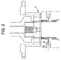
- a passage 22 communicates with annular space 20 (as shown in Fig. 2).
- a valve (not shown) can be mounted at thread 24.
- a rising ring 26 has a preferably L-shaped cross-section evidenced by a vertical segment 28 attached to a horizontal segment 30. The rising ring 26 acts as an indicator of pressure in annular space or cavity 20.
- a retaining ring 32 can be snapped into a groove 34 on the stem 12, where it acts as a travel stop for the horizontal segment 30.
- Fig. 1 illustrates that the rising ring 26 must be displaced downwardly to insert the retaining ring 32.
- the retaining ring 32 can be in the nature of a snap ring with end loops so that a pair of snap ring pliers into its loops can expand it into groove 34.
- ring 32 can be a spiral retaining ring, which is expanded over the stem 12 and snapped into groove 34 or any other suitable fastener to retain rising ring 26. Accordingly, unless the rising ring 26 is downwardly displaced, as shown in Fig. 1, the retaining ring 32 cannot be advanced into groove 34.
- Fig. 1 illustrates that the rising ring 26 must be displaced downwardly to insert the retaining ring 32.
- Fig. 3 also illustrates how the horizontal segment 30 acts as a travel stop, for rising ring 26, when it engages the retaining ring 32.
- the upper end 36 of the vertical segment 28 clearly extends beyond body 10 where it can serve as a signal that there is pressure under seal 18.
- the upper end 36 can be made a material having a high visibility color or it can be painted such a color. The length of the vertical segment 28 or the amount of vertical travel it has can be varied so as to make it even more apparent that a situation of pressure in annular space 20 exists.
- Fig. 2 illustrates that during normal operations, vertical segment 28 does not extend from body 12 and that there is a gap between the retaining ring 32 and horizontal segment 30 of rising ring 26. This gap is at its largest during assembly, as reflected in Fig. 1.
- Thread 24 can also accept a detector for local or remote signaling that a leak at seal 16 has occurred. Additionally, if remote indication of pressure in annular cavity 20 is desired a sensor can detect upward movement of rising ring 26 and an audible or visual alarm can be displayed remotely.
- the present invention can, due to its simplicity, be retrofitted into existing valve designs with no or minimal mold changes to the particular valve body.
- the present invention is particularly desirable because of its simplicity, ease of retrofit, and the interlock feature, which prevents removal of the retaining ring 32 even if operations or maintenance personnel ignore the signal from the extending upper end 36 of vertical segment 28 of rising ring 26. While the invention has been described as useful for valve stem seals, it has many applications in signaling leakage past other types of seals such as rotating or reciprocating shafts or as a telltale for zones where pressure is not anticipated but for some equipment malfunction in a variety of applications, not limited to valves.
Landscapes
- Engineering & Computer Science (AREA)
- General Engineering & Computer Science (AREA)
- Mechanical Engineering (AREA)
- Indication Of The Valve Opening Or Closing Status (AREA)
- Details Of Valves (AREA)
Description
- The field of this invention relates to visual indicators of pressure, particularly on valve stem seals, which act as a warning to personnel to relieve such pressure prior to attempting any disassembly.
- Valves of all types have been in use in the oil and gas industry for a variety of purposes. Valves have typically had stems that extend through their bodies with a manual or powered operator attached to the stem. Depending on the valve design these stems could be of the rising or non-rising type. The stem would feature a sealing system to prevent pressure inside the valve body from escaping. Stem seals could involve packing or seal rings or combinations of such devices. In some valves, there were two stem seals with access to an annular space between them through an opening, which was plugged or had a grease fitting. Some illustrative examples are
U.S. Patents 5,129,624 :3,544,064 (illustrating the use of a grease fitting): and4,575,101 . In some applications, the access to the annular space between an upper and lower stem seal featured the ability to add a sealing material under pressure or to mount a detector to sense leakage into the annular space between the stem seals. Some illustrative examples areU.S. Patents: 4,972,867 ; and4,364,542 . In yet another example, inU.S. Patent 4,230,299 the annular space between the two stem seals is in communication with a plug, which blows out upon leakage of a stem seal. This design is clearly inapplicable to toxic service because it may be fatal to personnel if the plug 144 blows at an inopportune time. Additionally, the fact that the plug 144 is not in place may be indicative of the fact that the plug was never installed or that, in the past, there was a leak past a stem seal but there may be no leakage problem at the present time. - In other designs, the annular area between the stem seals would be pressurized to a higher pressure level than seen in the valve body. This auxiliary pressure system would have a pressure source and a pressure accumulator chamber as well as some indication of the pressure in the auxiliary system being applied to the annular space. Pressure and fluid detectors were sometimes combined with such systems. Some examples are
U.S.Patents: 5,244,183 (note the pressure indicating rod 81 on the accumulator 34); and5,211,532 (note hinged flaps 73 which turn responsively to piston movement signaling fluid addition to the annular space). - The auxiliary systems just described had several negative attributes, which limited their application. These systems were expensive, took up space unavailable in some applications, added weight, increased fit-up time, and required additional maintenance above and beyond routine valve maintenance. The issue of routine valve maintenance raises important personnel safety questions. It is very unsafe for personnel to disassemble valve bonnets for the purpose of stem seal inspection or replacement when there is trapped pressure between the stem seals. Undeniably, some personnel are better trained in safety procedures. To these people it is a matter of routine to always vent the annular space between the stem seals before loosening the top bonnet. This can be simply accomplished by removing a plug in an opening in fluid communication with the annulus between the stem seals or, if there is one, by opening a valve in communication with the annulus. The problem is that some personnel are not as diligent and could release the bonnet with pressure on the upper stem seal. The released fluid or the bonnet being propelled by fluid pressure could cause a severe injury. One other attempt to deal with this problem in the past has been to put enough thread on the bonnet or its fasteners to allow pressurised fluid venting while the bonnet is still engaged to the valve body by a few threads. This procedure also raised several safety issues. If the fasteners or the bonnet were turned too quickly or if the threads failed to hold a severe accident could occur. Other valve designs of general interest are
US Patent: 4,940,208 ;4,497,340 ;4,510,966 ; and4,813,649 . - What is needed is a new paradigm in signalling operations and maintenance workers of the potential dangers of trapped fluid under a stem seal. The object of this invention is to provide just such a solution, which, upon more universal use in the industry, will reduce personal injuries when valves are inspected and maintained. In order to accomplish this ambitious goal, the proposed solution must be so simple in operation and readily integrated into existing valve body molds that it will gain universal acceptance. The objective of the present invention is to fulfill this need in the industry with a simple, economical design that, at a glance, provides the needed warning that pressure exists in the annular space between the stem seals.
US 5669414 discloses means to signal leakage of gas parts diaphragms used in valves. - According to the present invention there is provided a valve with a body and a stem, and telltale system to provide a visual signal of pressure in the valve body:
- whereby at least one seal is movably mounted around said stem and movable in response to pressure reaching it from the body;
- a signal member movably mounted in the body and displaceable by said seal so that at least a portion of said signal member extends from the body.
- A visual signal of pressure between valve stem seals may be given by a rising ring, which moves upwardly with an upper stem seal when there is pressure between the stem seals. The rising ring is held to the stem or valve body around the stem by a retaining ring. The rising ring, in its up position, precludes removal of the retaining ring.
-
- Figure 1 is a half section elevation view illustrating the installation of the locking ring;
- Figure 2 is a half section of Fig. 1, showing the rising ring in the normal position, with no pressure between the stem seals; and
- Figure 3 is the view of Fig. 1 with the rising ring in the up position due to pressure between the stem seals.
- Referring to Fig. 1, the valve V has a
body 10 and anon-rising stem 12, which has anupper end 14 extending out ofbody 10. Alower stem seal 16 and anupper stem seal 18 which are spaced apart to define anannular space 20 in betweensurround stem 12. Apassage 22 communicates with annular space 20 (as shown in Fig. 2). A valve (not shown) can be mounted atthread 24. A risingring 26 has a preferably L-shaped cross-section evidenced by avertical segment 28 attached to ahorizontal segment 30. The risingring 26 acts as an indicator of pressure in annular space orcavity 20. Aretaining ring 32 can be snapped into agroove 34 on thestem 12, where it acts as a travel stop for thehorizontal segment 30. - Fig. 1 illustrates that the rising
ring 26 must be displaced downwardly to insert theretaining ring 32. This is because theretaining ring 32 can be in the nature of a snap ring with end loops so that a pair of snap ring pliers into its loops can expand it intogroove 34. Alternatively,ring 32 can be a spiral retaining ring, which is expanded over thestem 12 and snapped intogroove 34 or any other suitable fastener to retain risingring 26. Accordingly, unless the risingring 26 is downwardly displaced, as shown in Fig. 1, theretaining ring 32 cannot be advanced intogroove 34. By the same token, as shown in Fig. 3, when there is pressure between theseals seal 18 and risingring 26 to rise in tandem, there is also no way to get theretaining ring 32 out. This is because the presence of thevertical segment 28 immediately surrounding retainingring 32 traps it intogroove 34, precluding its removal. Fig. 3 also illustrates how thehorizontal segment 30 acts as a travel stop, for risingring 26, when it engages the retaining ring 32.When this happens, theupper end 36 of thevertical segment 28 clearly extends beyondbody 10 where it can serve as a signal that there is pressure underseal 18. To aid in this signaling feature, theupper end 36 can be made a material having a high visibility color or it can be painted such a color. The length of thevertical segment 28 or the amount of vertical travel it has can be varied so as to make it even more apparent that a situation of pressure inannular space 20 exists. - The beauty of this system is that even if the operations or maintenance person fails to notice the visual signal presented by an extending
end 36 ofvertical segment 28 and an attempt is made to remove theretaining ring 32, it will not come out. The pressure acting onseal 18 and pushing it up with risingring 26 against retainingring 32 will trap the retainingring 32 to thestem 12 by virtue of peripheral contact from vertical segment 28(see Fig. 3). - Fig. 2 illustrates that during normal operations,
vertical segment 28 does not extend frombody 12 and that there is a gap between the retainingring 32 andhorizontal segment 30 of risingring 26. This gap is at its largest during assembly, as reflected in Fig. 1. - Those skilled in the art will appreciate that the preferred embodiment described above was for an installation with a non-rising stem. A simple adaptation can make this design workable for a rising stem valve. The L-shaped cross-section of the rising
ring 26 can simply be inverted and the retaining ring can be attached to thevalve body 10 instead of thestem 12.Thread 24 can also accept a detector for local or remote signaling that a leak atseal 16 has occurred. Additionally, if remote indication of pressure inannular cavity 20 is desired a sensor can detect upward movement of risingring 26 and an audible or visual alarm can be displayed remotely. The present invention can, due to its simplicity, be retrofitted into existing valve designs with no or minimal mold changes to the particular valve body. The present invention is particularly desirable because of its simplicity, ease of retrofit, and the interlock feature, which prevents removal of the retainingring 32 even if operations or maintenance personnel ignore the signal from the extendingupper end 36 ofvertical segment 28 of risingring 26. While the invention has been described as useful for valve stem seals, it has many applications in signaling leakage past other types of seals such as rotating or reciprocating shafts or as a telltale for zones where pressure is not anticipated but for some equipment malfunction in a variety of applications, not limited to valves. - The description of the invention above is illustrative of the preferred embodiment and the full scope of the invention can be determined from the claims, which appear below.
Claims (14)
- A valve with a body (10) and a stem (12), and a telltale system to provide a visual signal of pressure in the valve body (10);
whereby at least one seal (18) is movably mounted around said stem (12) and movable in response to pressure reaching it from the body (10);
a signal member (36) movably mounted in the body and displaceable by said seal (18) so that at least a portion of said signal member (36) extends from the body (10). - The valve of claim 1, further comprising:a travel stop (32) to limit the movement of said signal member (36) outwardly from the body (10).
- The valve of claim 2, wherein:said travel stop (32) is insertable and removable only when said signal member (36) does not extend from the body (10).
- The valve of claim 3, wherein:said travel stop (32) further comprises a ring, which is disposed in a groove (34);said signal member (36) when displaced by said seal (18) in a direction out of the body (10), encircles said ring, precluding its removal from said groove.
- The valve of claim 4, wherein:said signal member (36) has an L-shaped cross-section comprising a vertical component (28), which selectively extends from the body (10) and a horizontal component (38), which selectively engages said travel stop (32).
- The valve of claim 4, wherein:said groove is disposed on the stem (12).
- The valve of claim 4, wherein:said groove is disposed on the body (10).
- The valve of claim 1, wherein:said signal member (36) comprises an end having a bright color to facilitate observation that said end extends from the body (10).
- The valve of claim 2, wherein:said signal member (36) is movably mounted around the valve stem (12) in the body (10); andsaid travel stop (32) is secured to a groove located on the stem (12).
- The valve of claim 2, wherein:said signal member (36) is movably mounted around the valve stem (12) in the body; andsaid travel stop (32) is secured to a groove located on the body (10).
- The valve of claim 9, wherein:said at least one seal (18) comprises a stationary lower seal (16) and a movable upper seal (18) both disposed around the valve stem (23) to seal off an annular space (20) in the body (10) around the stem, whereupon leakage of fluid from the body past said lower seal, said annular cavity is pressurized and said upper seal and signal member (36) move in tandem with respect to the valve stem (12) until said travel stop (32) is engaged and a portion of said signal member (36) extends out of the body.
- A valve according to any of claims 1 to 11, characterised in that the telltale system is a leakage indicating system, wherein:the valve stem (12) extends out of an opening in the valve body;the signal member is movably mounted for tandem movement with said seal.
- The valve of claim 12 when dependent on claim 2, wherein:said travel stop (32) and said signal member (36) cannot be removed when they are in contact with each other.
- The valve of claim 12, when dependent on claim 5, wherein:said ring snaps into said groove (34);said vertical component (28) selectively encircles said ring to keep it from being removed from said groove.
Applications Claiming Priority (3)
| Application Number | Priority Date | Filing Date | Title |
|---|---|---|---|
| US09/767,789 US6554024B2 (en) | 2001-01-23 | 2001-01-23 | Stem seal pressure telltale |
| US767789 | 2001-01-23 | ||
| PCT/US2001/051117 WO2002059514A1 (en) | 2001-01-23 | 2001-12-19 | Valve with pressure indicator |
Publications (2)
| Publication Number | Publication Date |
|---|---|
| EP1266165A1 EP1266165A1 (en) | 2002-12-18 |
| EP1266165B1 true EP1266165B1 (en) | 2007-07-25 |
Family
ID=25080589
Family Applications (1)
| Application Number | Title | Priority Date | Filing Date |
|---|---|---|---|
| EP01992461A Expired - Lifetime EP1266165B1 (en) | 2001-01-23 | 2001-12-19 | Valve with pressure indicator |
Country Status (7)
| Country | Link |
|---|---|
| US (1) | US6554024B2 (en) |
| EP (1) | EP1266165B1 (en) |
| BR (1) | BR0109474B1 (en) |
| CA (1) | CA2404065C (en) |
| MX (1) | MXPA02009307A (en) |
| NO (1) | NO325782B1 (en) |
| WO (1) | WO2002059514A1 (en) |
Families Citing this family (22)
| Publication number | Priority date | Publication date | Assignee | Title |
|---|---|---|---|---|
| US7988127B2 (en) * | 2006-12-29 | 2011-08-02 | Gregory J Parra | Valve with self-expanding seals |
| US8870233B2 (en) * | 2007-07-03 | 2014-10-28 | S.P.M. Flow Control, Inc. | Swivel joint with uniform ball bearing requirements |
| MX2011011007A (en) | 2009-04-20 | 2012-02-13 | Spm Flow Control Inc | Flowline flapper valve. |
| CA2767042C (en) | 2009-06-03 | 2017-08-15 | S.P.M. Flow Control, Inc. | Plug valve indicator |
| CA2882169C (en) | 2012-08-16 | 2020-04-21 | S.P.M. Flow Control, Inc. | Plug valve having preloaded seal segments |
| US9322243B2 (en) | 2012-08-17 | 2016-04-26 | S.P.M. Flow Control, Inc. | Automated relief valve control system and method |
| US9273543B2 (en) | 2012-08-17 | 2016-03-01 | S.P.M. Flow Control, Inc. | Automated relief valve control system and method |
| ES2467490B1 (en) * | 2012-11-12 | 2015-03-24 | Talleres Gilabert Sorribes, S.L. | Hermetic sealing device for industrial valves |
| USD707332S1 (en) | 2013-03-15 | 2014-06-17 | S.P.M. Flow Control, Inc. | Seal assembly |
| USD707797S1 (en) | 2013-03-15 | 2014-06-24 | S.P.M. Flow Control, Inc. | Seal segment |
| WO2015002863A1 (en) | 2013-07-01 | 2015-01-08 | S.P.M. Flow Control, Inc. | Manifold assembly |
| FR3015612B1 (en) * | 2013-12-19 | 2016-06-10 | Valeo Systemes Thermiques | DEVICE FOR JOINING A BOOM OF A LIQUID CIRCULATION VALVE, ESPECIALLY A COOLING LIQUID FOR A MOTOR VEHICLE, AND VALVE COMPRISING SUCH AN ARTICULATION DEVICE |
| KR101592657B1 (en) * | 2013-12-30 | 2016-02-12 | 현대자동차주식회사 | Valve for controlling coolant fuel cell stack coolant of fuel cell vehicle |
| ITMI20142265A1 (en) * | 2014-12-29 | 2016-06-29 | Nuovo Pignone Srl | SEALING DEVICE FOR THE STEM OF A VALVE |
| CN107407138A (en) * | 2015-01-30 | 2017-11-28 | 爱默生伏尔甘控股有限责任公司 | Choke valve wear monitoring system and method |
| CA2989626C (en) | 2015-06-15 | 2023-08-29 | S.P.M. Flow Control, Inc. | Full-root-radius-threaded wing nut having increased wall thickness |
| US10677365B2 (en) | 2015-09-04 | 2020-06-09 | S.P.M. Flow Control, Inc. | Pressure relief valve assembly and methods |
| US20220040714A1 (en) * | 2018-12-21 | 2022-02-10 | Abb Schweiz Ag | Valve |
| CN111946841A (en) * | 2019-05-15 | 2020-11-17 | 北京同方洁净技术有限公司 | Sealing monitoring system for valve sealing state and using method thereof |
| SE2051158A1 (en) * | 2020-10-02 | 2021-12-07 | Roxtec Ab | A guard sensor device for use with a cable, pipe or wire transit, and a method of guarding a cable, pipe or wire transit |
| CN113790274B (en) * | 2021-09-18 | 2024-01-26 | 湖南东麒能源有限公司 | Outdoor air valve |
| US12098753B2 (en) * | 2021-12-03 | 2024-09-24 | Revmax Performance, Llc | Roller clutch assembly |
Family Cites Families (20)
| Publication number | Priority date | Publication date | Assignee | Title |
|---|---|---|---|---|
| US3544064A (en) | 1969-07-11 | 1970-12-01 | Bernard Carlin | Blow-out proof packing for axially movable rod or shaft |
| US3912221A (en) | 1974-06-26 | 1975-10-14 | United States Pipe Foundry | Stem seal and retainer for gate valve |
| US4272055A (en) | 1976-02-06 | 1981-06-09 | Mcevoy Oilfield Equipment Company | Single double backseat |
| US4230299A (en) | 1978-07-03 | 1980-10-28 | Petroleum Designers, Inc. | Pressure balanced gate valve having selective actuator systems |
| US4379557A (en) | 1981-03-05 | 1983-04-12 | Acf Industries, Incorporated | Valve stem packing structure |
| US4364542A (en) | 1981-06-18 | 1982-12-21 | Acf Industries, Incorporated | Packing gland assembly |
| US4499846A (en) * | 1982-12-15 | 1985-02-19 | B.W.B. Controls, Inc. | Plunger and transparent indicator |
| US4497340A (en) | 1983-01-24 | 1985-02-05 | Amsted Industries Incorporated | Seal for post indicator valve assembly |
| US4510966A (en) | 1983-03-28 | 1985-04-16 | Garlock, Inc. | Plug valve with floating stem seal |
| US4575101A (en) | 1984-09-12 | 1986-03-11 | Chevron Research Company | Device for safe on-stream addition of valve packing |
| US4813648A (en) | 1987-11-25 | 1989-03-21 | Fisher Controls International, Inc. | Sanitary valve |
| US4940208A (en) | 1989-01-10 | 1990-07-10 | Kemp Development Corporation | Ball valve |
| US4972867A (en) | 1989-11-03 | 1990-11-27 | Ruesch J O | Valve stem seal leak protection and detection apparatus |
| US5211532A (en) | 1990-04-21 | 1993-05-18 | David Brown Engineering Limited | Apparatus for applying a back pressure to a pump drive shaft seal |
| US5129624A (en) | 1990-11-15 | 1992-07-14 | M&Fc Holding Company, Inc. | Valve stem sealing means for prevention of fugitive emissions |
| US5244183A (en) | 1991-03-20 | 1993-09-14 | Keystone International Holdings Corp. | Fugitive emission sealing assembly |
| US5170659A (en) * | 1991-04-08 | 1992-12-15 | Kemp Development Corporation | Apparatus and method for detecting fluid leakage |
| US5540253A (en) * | 1994-11-16 | 1996-07-30 | Triten Corporation | Plug valve |
| US5607165A (en) | 1995-06-07 | 1997-03-04 | Cooper Cameron Corporation | Sealing system for a valve having biassed sealant under pressure |
| US5669414A (en) * | 1995-11-20 | 1997-09-23 | Vemco Corporation | Pop-alert device |
-
2001
- 2001-01-23 US US09/767,789 patent/US6554024B2/en not_active Expired - Lifetime
- 2001-12-19 MX MXPA02009307A patent/MXPA02009307A/en active IP Right Grant
- 2001-12-19 BR BRPI0109474-2A patent/BR0109474B1/en not_active IP Right Cessation
- 2001-12-19 WO PCT/US2001/051117 patent/WO2002059514A1/en not_active Ceased
- 2001-12-19 CA CA002404065A patent/CA2404065C/en not_active Expired - Fee Related
- 2001-12-19 EP EP01992461A patent/EP1266165B1/en not_active Expired - Lifetime
-
2002
- 2002-09-18 NO NO20024461A patent/NO325782B1/en not_active IP Right Cessation
Non-Patent Citations (1)
| Title |
|---|
| None * |
Also Published As
| Publication number | Publication date |
|---|---|
| US20020096218A1 (en) | 2002-07-25 |
| WO2002059514A1 (en) | 2002-08-01 |
| US6554024B2 (en) | 2003-04-29 |
| NO20024461D0 (en) | 2002-09-18 |
| MXPA02009307A (en) | 2003-03-12 |
| NO20024461L (en) | 2002-10-29 |
| BR0109474B1 (en) | 2010-11-03 |
| CA2404065A1 (en) | 2002-08-01 |
| CA2404065C (en) | 2009-09-08 |
| NO325782B1 (en) | 2008-07-14 |
| BR0109474A (en) | 2003-06-03 |
| EP1266165A1 (en) | 2002-12-18 |
Similar Documents
| Publication | Publication Date | Title |
|---|---|---|
| CA2404065C (en) | Valve with pressure indicator | |
| EP2406520B1 (en) | Gas cylinder actuator with overtravel safety device | |
| KR101663144B1 (en) | Gas cylinder actuator with safety system for controlled ejection of the piston stem | |
| US5607165A (en) | Sealing system for a valve having biassed sealant under pressure | |
| CN104981640B (en) | Rotary top shaft valve actuator | |
| AU2010203056B2 (en) | Wheel disassembly safety system | |
| US4651670A (en) | Pressure indicating device | |
| US20130248001A1 (en) | Low profile hydraulic actuator | |
| CA1266853A (en) | Fail-safe valve actuator | |
| US5727586A (en) | Reclosing collapsible pin pressure relief valve | |
| EP1281908B1 (en) | A coupling | |
| US20140138082A1 (en) | Thermally-sensitive triggering mechanism for selective mechanical energization of annular seal element | |
| US4831957A (en) | First trip indicator for sensing devices of production control and safety systems | |
| US4245662A (en) | Heat responsive back seat arrangement for valve operator with fusible lock-out cap | |
| EP2577132B1 (en) | Control vaive pressure bleed inspection port | |
| CA2394885C (en) | Control valve pressure bleed inspection port | |
| CA2043899C (en) | Bonnet nut with improved safety characteristics | |
| GB2261029A (en) | Fluid operated acuator overstroke prevention. | |
| EP0071348A2 (en) | Improvements in cylinder assemblies | |
| EP2118545B1 (en) | Device for monitoring a hermetically sealed valve interior | |
| EP1722141A2 (en) | Control valve pressure bleed inspection port | |
| RU2518782C1 (en) | Safety valve of single action | |
| JPS61197864A (en) | Failsafe valve actuator |
Legal Events
| Date | Code | Title | Description |
|---|---|---|---|
| PUAI | Public reference made under article 153(3) epc to a published international application that has entered the european phase |
Free format text: ORIGINAL CODE: 0009012 |
|
| 17P | Request for examination filed |
Effective date: 20020925 |
|
| AK | Designated contracting states |
Kind code of ref document: A1 Designated state(s): AT BE CH CY DE DK ES FI FR GB GR IE IT LI LU MC NL PT SE TR |
|
| AX | Request for extension of the european patent |
Free format text: AL;LT;LV;MK;RO;SI |
|
| RIN1 | Information on inventor provided before grant (corrected) |
Inventor name: GUTMANN, PAUL, M. Inventor name: ARD, DARYL, L. Inventor name: MEFFORD, DAVID, R. |
|
| 17Q | First examination report despatched |
Effective date: 20040609 |
|
| REG | Reference to a national code |
Ref country code: DE Ref legal event code: 8566 |
|
| GRAP | Despatch of communication of intention to grant a patent |
Free format text: ORIGINAL CODE: EPIDOSNIGR1 |
|
| RBV | Designated contracting states (corrected) |
Designated state(s): FR GB IT |
|
| GRAS | Grant fee paid |
Free format text: ORIGINAL CODE: EPIDOSNIGR3 |
|
| GRAA | (expected) grant |
Free format text: ORIGINAL CODE: 0009210 |
|
| AK | Designated contracting states |
Kind code of ref document: B1 Designated state(s): FR GB IT |
|
| REG | Reference to a national code |
Ref country code: GB Ref legal event code: FG4D |
|
| ET | Fr: translation filed | ||
| PLBE | No opposition filed within time limit |
Free format text: ORIGINAL CODE: 0009261 |
|
| STAA | Information on the status of an ep patent application or granted ep patent |
Free format text: STATUS: NO OPPOSITION FILED WITHIN TIME LIMIT |
|
| 26N | No opposition filed |
Effective date: 20080428 |
|
| PGFP | Annual fee paid to national office [announced via postgrant information from national office to epo] |
Ref country code: GB Payment date: 20101123 Year of fee payment: 10 |
|
| PGFP | Annual fee paid to national office [announced via postgrant information from national office to epo] |
Ref country code: FR Payment date: 20111205 Year of fee payment: 11 |
|
| GBPC | Gb: european patent ceased through non-payment of renewal fee |
Effective date: 20121219 |
|
| REG | Reference to a national code |
Ref country code: FR Ref legal event code: ST Effective date: 20130830 |
|
| PG25 | Lapsed in a contracting state [announced via postgrant information from national office to epo] |
Ref country code: FR Free format text: LAPSE BECAUSE OF NON-PAYMENT OF DUE FEES Effective date: 20130102 Ref country code: GB Free format text: LAPSE BECAUSE OF NON-PAYMENT OF DUE FEES Effective date: 20121219 |
|
| PGFP | Annual fee paid to national office [announced via postgrant information from national office to epo] |
Ref country code: IT Payment date: 20141217 Year of fee payment: 14 |
|
| PG25 | Lapsed in a contracting state [announced via postgrant information from national office to epo] |
Ref country code: IT Free format text: LAPSE BECAUSE OF NON-PAYMENT OF DUE FEES Effective date: 20151219 |