EP1265237A2 - Cartridge magnetic tape device having magnetic head cleaning mechanism - Google Patents
Cartridge magnetic tape device having magnetic head cleaning mechanism Download PDFInfo
- Publication number
- EP1265237A2 EP1265237A2 EP02253913A EP02253913A EP1265237A2 EP 1265237 A2 EP1265237 A2 EP 1265237A2 EP 02253913 A EP02253913 A EP 02253913A EP 02253913 A EP02253913 A EP 02253913A EP 1265237 A2 EP1265237 A2 EP 1265237A2
- Authority
- EP
- European Patent Office
- Prior art keywords
- threading
- magnetic tape
- magnetic head
- pin
- tape device
- Prior art date
- Legal status (The legal status is an assumption and is not a legal conclusion. Google has not performed a legal analysis and makes no representation as to the accuracy of the status listed.)
- Withdrawn
Links
Images




Classifications
-
- G—PHYSICS
- G11—INFORMATION STORAGE
- G11B—INFORMATION STORAGE BASED ON RELATIVE MOVEMENT BETWEEN RECORD CARRIER AND TRANSDUCER
- G11B15/00—Driving, starting or stopping record carriers of filamentary or web form; Driving both such record carriers and heads; Guiding such record carriers or containers therefor; Control thereof; Control of operating function
- G11B15/60—Guiding record carrier
- G11B15/66—Threading; Loading; Automatic self-loading
- G11B15/67—Threading; Loading; Automatic self-loading by extracting end of record carrier from container or spool
- G11B15/672—Extracting end of record carrier from container or single reel
-
- G—PHYSICS
- G11—INFORMATION STORAGE
- G11B—INFORMATION STORAGE BASED ON RELATIVE MOVEMENT BETWEEN RECORD CARRIER AND TRANSDUCER
- G11B5/00—Recording by magnetisation or demagnetisation of a record carrier; Reproducing by magnetic means; Record carriers therefor
- G11B5/41—Cleaning of heads
Definitions
- the present invention relates to a cartridge magnetic tape device, especially to a mechanism for cleaning a magnetic head of the cartridge magnetic tape device.
- a cleaning operation for a magnetic head is indispensable to implement more stable reading/writing (R/W) operations from/to a magnetic tape.
- R/W reading/writing
- a cleaning member is disposed out of a threading track.
- the cleaning m ember is moved by a threader arm so that the cleaning member comes into contact with the magnetic head, and then the thr eader arm is reciprocally moved with a predetermined stroke, whereby the magnetic head is rubbed by the cleaning member.
- a magnetic tape device comprising a magnetic head; a threading arm; a threading motor for driving the threading arm; a threading pin attached to the thr eading arm; a guide along which the threading pin is moved in connection w ith driving of the threading arm; and a leader block attached to the thr eading pin for drawing out a leader pin from a magnetic tape cartridge, the leader pin being fixed at a tip of a magnetic tape accom modated in the magnetic tape cartridge, wherein the leader block has a brush for cleaning the magnetic head by contacting ther ewith.
- the thr eading arm is driven through both a drive shaft driven by the threading motor and a drive arm one end of which is secured to the drive shaft while another end of which is rotatably connected to the threading arm.
- the leader block is rotatably attached to the threading pin.
- the thr eading pin has a bear ing by which the threading pin is moved along the guide.
- the m agnetic tape device further comprises a sensor for detecting the threading pin, especially the bearing thereof, at a position where the brush is brought into contact w ith the magnetic head, wherein the threading motor is stopped on the basis of detection result, and the magnetic head is moved across a direction of magnetic tape threading.
- the frequency of movement of the magnetic head is set in accor dance with the dirt degree of the magnetic head.
- the magnetic tape device further comprises a lead screw for moving the magnetic head, and a motor for rotating the lead screw, wherein the motor is forwardly and inversely rotated to move the magnetic head along the lead screw, or, further comprises a voice coil for moving the magnetic head.
- the mechanism for cleaning the magnetic head and the magnetic tape threading mechanism are integrated, and thus it is unnecessar y to provide a cleaning m echanism independently, so that the number of parts can be reduced and the little- space design of the device can be implemented.
- Figs. 2A and 2B are a plan view and front view, respectively, showing a cartridge magnetic tape device em bodying the present invention
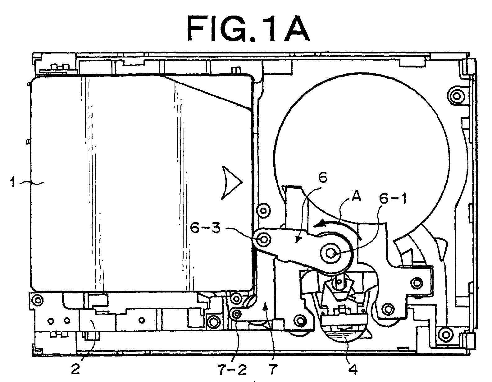
- F igs. 1A, 1B and 1C are a plan view, front view and rear view, respectively, showing the cartridge magnetic tape device of Figs. 2A and 2B, in which a guide plate is removed.
- a magnetic tape cartridge 1 is loaded on a deck base 2 at a predetermined position for tape threading.
- Figs. 4A and 4B are a plan view and front view showing the magnetic tape cartridge 1.
- a magnetic tape 1-1 is accommodated at a taken-up form.
- a leader pin 1-2 is secured to the tip of the magnetic tape 1-1.
- reference numeral 5 represents a threading motor fixed onto the deck base 2
- reference numeral 5-1 represents a shaft of the threading motor 5 extending in the vertical direction
- reference numeral 5-2 represents a gear fixed to the tip of the shaft 5-1
- Reference numeral 6-1 represents a drive shaft extending in the vertical direction and rotatably secured to the deck base 2
- r eference numeral 6-2 represents a gear secured to the tip of the drive shaft 6-1 and engaged with the gear 5-2.
- a drive arm 6 is secured to the tip of the drive shaft 6-1. Further, as shown in Fig. 1A, to another end portion of the drive arm 6 one end portion of a threading arm 7 is rotatably secured through a pin 6-3 extending in vertical direction, and to another end portion of the threading arm 7 a threading pin 7-1 extending in vertical direction is attached. As shown in Figs. 1B and 2B, the threading pin 7-1 has a bearing 7-2 at the upper portion thereof, and a leader block 8 is rotatably secured to the threading pin 7-1.
- a magnetic head 4 is fixed on the deck base 2.
- Reference numeral 4-1 represents a head portion of the magnetic head 4 on which the magnetic tape 1-1 is threaded.
- the bearing 7-2 fits into a guide 3-1 formed on a guide plate 3 which is secured to the deck base 2.
- Fig. 3 is a perspective view showing the leader block 8.
- the leader block 8 is equipped w ith pawls 8-1 which are hooked to the leader pin 1-2 fixed to the tip of a magnetic tape 1-1, and also with a brush 8-2 for cleaning the head portion 4-1 of the magnetic head 4.
- Figs. 6A and 6B are a plan view and front view, respectively, showing the cartridge magnetic tape device em bodying the present invention to explain an approaching operation of the leader block to the magnetic head
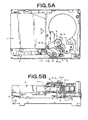
- Figs. 5A and 5B are a plan view and front view, respectively, showing the cartridge magnetic tape device of Figs. 6A and 6B, in which the guide plate is removed.
- Fig. 6A clearly shows that the bearing 7-2 at the upper portion of the threading pin 7-1 is moved in the direction of the arrow B along the guide 3-1.
- the magnetic tape 1-1 drawn out of the magnetic tape cartridge 1 is shown in Figs. 5A, 5B and 6B.
- the leader block 8 passes the front side of the magnetic head 4 while drawing out the magnetic tape 1-1. At this time, the head portion 4-1 is cleaned by the brush 8-2 fixed to the leader block 8.
- Figs. 8A and 8B are a plan view and front view, respectively, showing the cartridge magnetic tape device em bodying the present invention at the time when the brush 8-2 passes the head portion 4-1
- Figs. 7A and 7B are a plan view and front view, respectively, showing the cartridge magnetic tape device of Figs. 8A and 8B, in which the guide plate is r emoved.
- Fig. 8A clearly shows that the bearing 7-2 at the upper portion of the threading pin 7-1 is moved in the direction of the arrow B along the guide 3-1.
- Fig. 9 is an enlarged plan view when the brush 8-2 and the head portion 4-1 are brought into contact with each other.
- the head portion 4-1 is cleaned through the contact between the brush 8-2 and the head portion 4-1. That is, at the time when the leader block 8 for threading the magnetic tape 1-1 passes the front side of the magnetic head 4, the head portion 4-1 is cleaned by a brush equipped to the leader block 8.
- Figs. 10A and 10B are a perspective view and front view, respectively, showing a magnetic head according to another embodiment of the present invention.
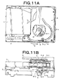
- F igs. 11A and 11B are a plan view and front view, respectively, showing the embodiment of the cartridge magnetic tape device according to the present invention in which the magnetic head of Figs. 10A and 10B is used.
- the magnetic head 4 is upw ardly/downwardly, i.e. vertically, moved in the cleaning operation. Accordingly, the magnetic head 4 can be more effectively cleaned.
- a motor 9 for moving the magnetic head 4 upw ardly/downwardly is fixed on a bracket 9-2 secured to the deck base 2, and the magnetic head 4 is moved upwardly/downwardly through a lead screw 9-1 extending in vertical direction and engaged with a nut 4-2 fixed to the magnetic head 4 when the motor 9 rotates in both rotational directions alternately.
- a sensor 10 is disposed at such a position on the guide plate 3 that it detects the position of the bearing 7-2 when the brush 8-2 is located in front of the head portion 4-1.
- the threading motor 5 is temporarily stopped. Thereafter, the motor 9 rotates forwardly and inversely, i.e. in both the rotational directions, to move the magnetic head 4 upwardly and downwardly, and the head portion 4-1 of the magnetic head 4 is cleaned by the brush 8-2.
- the cleaning oper ation is carried out while the brush 8-2 is stopped and the magnetic head 4 is moved upwardly and downwardly, so that the frequency of the cleaning can be set to any value. Accordingly, when the magnetic head is remarkably dirty, the effective operation can be performed.
- a voice coil may be used to move the magnetic head 4 upw ardly and downwardly to achieve the same effect.
- the embodiments illustrated integrate a threading mechanism and a magnetic head cleaning m echanism so that the head portion of a magnetic head is cleaned by a brush provided to a leader block for threading the magnetic tape when the leader block passes the front side of the magnetic head.
Landscapes
- Adjustment Of The Magnetic Head Position Track Following On Tapes (AREA)
- Supports Or Holders For Household Use (AREA)
- Moving Of Heads (AREA)
Abstract
Description
Claims (9)
- A magnetic tape device, comprising:a magnetic head;a threading arm;a threading motor for driving the threading arm;a threading pin attached to said thr eading arm;a guide along which said threading pin is moved in connection w ith driving of said threading arm; anda leader block attached to said thr eading pin for drawing out a leader pin from a magnetic tape cartridge, said leader pin being fixed at a tip of a magnetic tape accommodated in the magnetic tape cartridge, wherein said leader block has a brush for cleaning said magnetic head by contacting therewith.
- The magnetic tape device as claim ed in claim 1, wherein said threading arm is driven through both a drive shaft driven by said threading motor and a drive arm one end of which is secured to the drive shaft while another end of which is rotatably connected to said threading arm.
- The magnetic tape device as claim ed in claim 1 or 2, wherein said leader block is rotatably attached to said threading pin.
- The magnetic tape device as claim ed in claim 1, 2 or 3, wherein said threading pin has a bearing by which the threading pin is moved along said guide.
- The magnetic tape device as claim ed in claim 4, further comprising a sensor for detecting said bearing at a position where said brush is brought into contact with said magnetic head, wherein said threading motor is stopped on the basis of detection result, and said magnetic head is moved across a direction of magnetic tape thr eading.
- The magnetic tape device as claim ed in any of claims 1 to 5, further comprising a sensor for detecting said threading pin at a position w here said brush is brought into contact with said magnetic head, wherein said threading motor is stopped on the basis of detection result, and said magnetic head is moved across a direction of magnetic tape threading.
- The magnetic tape device as claim ed in claim 6, wherein the frequency of movement of said magnetic head is set in accordance with dirt degree of said magnetic head.
- The magnetic tape device as claim ed in claim 6 or 7, further comprising a lead screw for moving said magnetic head, and a m otor for rotating said lead screw, wherein said motor is forwardly and inversely rotated to move said magnetic head along said lead screw.
- The magnetic tape device as claim ed in claim 6, 7 or 8, further comprising a voice coil for moving said magnetic head.
Applications Claiming Priority (2)
| Application Number | Priority Date | Filing Date | Title |
|---|---|---|---|
| JP2001168998A JP2002367127A (en) | 2001-06-05 | 2001-06-05 | Magnetic head cleaner mechanism for cartridge magnetic tape device |
| JP2001168998 | 2001-06-05 |
Publications (2)
| Publication Number | Publication Date |
|---|---|
| EP1265237A2 true EP1265237A2 (en) | 2002-12-11 |
| EP1265237A3 EP1265237A3 (en) | 2006-05-03 |
Family
ID=19011128
Family Applications (1)
| Application Number | Title | Priority Date | Filing Date |
|---|---|---|---|
| EP02253913A Withdrawn EP1265237A3 (en) | 2001-06-05 | 2002-06-05 | Cartridge magnetic tape device having magnetic head cleaning mechanism |
Country Status (3)
| Country | Link |
|---|---|
| US (1) | US6697212B2 (en) |
| EP (1) | EP1265237A3 (en) |
| JP (1) | JP2002367127A (en) |
Cited By (1)
| Publication number | Priority date | Publication date | Assignee | Title |
|---|---|---|---|---|
| US7372668B2 (en) * | 2004-11-25 | 2008-05-13 | Mitsumi Electric Co., Ltd. | Recording and/or reproducing device having a positioning arrangement for positioning a cleaning brush |
Families Citing this family (16)
| Publication number | Priority date | Publication date | Assignee | Title |
|---|---|---|---|---|
| JP3592228B2 (en) * | 2000-10-24 | 2004-11-24 | Necパーソナルプロダクツ株式会社 | Magnetic head cleaner mechanism |
| US6621656B2 (en) * | 2001-04-05 | 2003-09-16 | Storage Technology Corporation | Moveable tape guide cleaning member |
| US6867947B2 (en) * | 2002-08-27 | 2005-03-15 | International Business Machines Corporation | Retractable low profile head brush assembly for cleaning read/write heads in a media tape drive |
| US20040169960A1 (en) * | 2003-02-27 | 2004-09-02 | Havard Hoelsaeter | Head cleaning device for tape drive |
| US6921038B2 (en) * | 2003-08-15 | 2005-07-26 | International Business Machines Corporation | Apparatus and method to releaseably attach a tape leader pin |
| JP4776206B2 (en) * | 2004-10-22 | 2011-09-21 | 株式会社キャタラー | Platinum-rhodium catalyst for automobile exhaust gas |
| US7099101B2 (en) * | 2004-11-01 | 2006-08-29 | International Business Machines Corporation | Apparatus, system, and method for determining contact with a magnetic head in a tape drive |
| US20060227459A1 (en) * | 2005-04-11 | 2006-10-12 | Quantum Corporation | Integrated tape and data transducer head cleaning device |
| US7965469B2 (en) | 2006-07-25 | 2011-06-21 | Hitachi Maxwell, Ltd. | Tape cartridge and tape loading system using same |
| JP4707151B2 (en) * | 2006-07-25 | 2011-06-22 | 日立マクセル株式会社 | Tape cartridge |
| JP4711344B2 (en) * | 2006-08-02 | 2011-06-29 | 日立マクセル株式会社 | Single reel type tape cartridge |
| US7782567B2 (en) * | 2007-07-23 | 2010-08-24 | International Business Machines Corporation | Cleaning system for tape head and tape drive system implementing same |
| JP2010238349A (en) * | 2009-03-12 | 2010-10-21 | Nec Personal Products Co Ltd | Magnetic head cleaning mechanism and magnetic tape device |
| US9123377B1 (en) * | 2014-10-03 | 2015-09-01 | Oracle International Corporation | Apparatus and method for allowing passage of a leader through a tape drive tape path |
| JP6596054B2 (en) | 2017-10-19 | 2019-10-23 | Necプラットフォームズ株式会社 | Magnetic head cleaning mechanism and magnetic tape device |
| JP6616539B1 (en) * | 2019-02-15 | 2019-12-04 | Necプラットフォームズ株式会社 | Cleaning enabling device, cleaning device and magnetic tape device |
Family Cites Families (9)
| Publication number | Priority date | Publication date | Assignee | Title |
|---|---|---|---|---|
| JPH06131637A (en) * | 1992-10-15 | 1994-05-13 | Fujitsu Ltd | Cleaning mechanism for magnetic tape unit |
| US5463519A (en) * | 1994-04-14 | 1995-10-31 | Storage Technology Corporation | Apparatus for cleaning a tape path in a tape drive |
| US6067211A (en) * | 1996-04-03 | 2000-05-23 | International Business Machines Corporation | Oscillating magnetic head and stationary brush cleaning apparatus |
| JPH11328635A (en) | 1998-05-19 | 1999-11-30 | Fujitsu Ltd | Magnetic tape unit |
| US6067212A (en) * | 1998-08-25 | 2000-05-23 | Hewlett-Packard Company | Tape drive head cleaner embedded in cartridge/drive leader block |
| JP3466097B2 (en) | 1998-11-02 | 2003-11-10 | 富士通株式会社 | Magnetic tape unit |
| US6215618B1 (en) * | 1998-11-06 | 2001-04-10 | Hewlett-Packard Co. | Linear tape drive head cleaning process |
| JP3390385B2 (en) * | 1999-11-05 | 2003-03-24 | 米沢日本電気株式会社 | Threading mechanism in magnetic recording / reproducing device |
| JP3592228B2 (en) * | 2000-10-24 | 2004-11-24 | Necパーソナルプロダクツ株式会社 | Magnetic head cleaner mechanism |
-
2001
- 2001-06-05 JP JP2001168998A patent/JP2002367127A/en active Pending
-
2002
- 2002-06-05 US US10/161,683 patent/US6697212B2/en not_active Expired - Fee Related
- 2002-06-05 EP EP02253913A patent/EP1265237A3/en not_active Withdrawn
Cited By (1)
| Publication number | Priority date | Publication date | Assignee | Title |
|---|---|---|---|---|
| US7372668B2 (en) * | 2004-11-25 | 2008-05-13 | Mitsumi Electric Co., Ltd. | Recording and/or reproducing device having a positioning arrangement for positioning a cleaning brush |
Also Published As
| Publication number | Publication date |
|---|---|
| EP1265237A3 (en) | 2006-05-03 |
| US6697212B2 (en) | 2004-02-24 |
| JP2002367127A (en) | 2002-12-20 |
| US20020181145A1 (en) | 2002-12-05 |
Similar Documents
| Publication | Publication Date | Title |
|---|---|---|
| EP1265237A2 (en) | Cartridge magnetic tape device having magnetic head cleaning mechanism | |
| JP3834817B2 (en) | Measuring head | |
| JP3592228B2 (en) | Magnetic head cleaner mechanism | |
| EP1089260B1 (en) | Magnetic head cleaner | |
| JP3466097B2 (en) | Magnetic tape unit | |
| JP2001206510A (en) | Pushers, pullers and loaders, unloaders and working equipment | |
| US6163439A (en) | Head loading device and method in a hard disk drive | |
| KR100579085B1 (en) | Tool magazine feeder of automatic tool changer | |
| US7372668B2 (en) | Recording and/or reproducing device having a positioning arrangement for positioning a cleaning brush | |
| JPS582069Y2 (en) | Wiring structure of lead wire in rotating head device | |
| JP4196057B2 (en) | Dijector device | |
| JPH0457535B2 (en) | ||
| JP2508187B2 (en) | Dustproof device for Cartesian coordinate robot | |
| US12526970B2 (en) | Shaft drive device and component mounting device | |
| US6708913B2 (en) | Magnetic tape unit | |
| JP2713747B2 (en) | Recording / reproducing device for card-shaped information recording medium | |
| KR0122090Y1 (en) | Connection structure of printed circuit board for drum motor of VCR | |
| JP4150848B2 (en) | Single reel type magnetic tape device and method for cleaning the cleaning area | |
| JPH036290Y2 (en) | ||
| US20060139811A1 (en) | Suspension and actuator with the same for use in hard disk drive | |
| JPH06119733A (en) | Head retracting mechanism of magnetic disk device | |
| KR100518890B1 (en) | Flexible Printed Circuit Cable Guide Mechanism | |
| JPH0335598Y2 (en) | ||
| JPS62165719A (en) | Magnetic head cleaning device for magnetic recording and reproducing device | |
| JPH03288308A (en) | Rotary head cleaning device |
Legal Events
| Date | Code | Title | Description |
|---|---|---|---|
| PUAI | Public reference made under article 153(3) epc to a published international application that has entered the european phase |
Free format text: ORIGINAL CODE: 0009012 |
|
| AK | Designated contracting states |
Kind code of ref document: A2 Designated state(s): AT BE CH CY DE DK ES FI FR GB GR IE IT LI LU MC NL PT SE TR |
|
| AX | Request for extension of the european patent |
Free format text: AL;LT;LV;MK;RO;SI |
|
| PUAL | Search report despatched |
Free format text: ORIGINAL CODE: 0009013 |
|
| AK | Designated contracting states |
Kind code of ref document: A3 Designated state(s): AT BE CH CY DE DK ES FI FR GB GR IE IT LI LU MC NL PT SE TR |
|
| AX | Request for extension of the european patent |
Extension state: AL LT LV MK RO SI |
|
| RIC1 | Information provided on ipc code assigned before grant |
Ipc: G11B 15/18 20060101ALI20060313BHEP Ipc: G11B 23/107 20060101ALI20060313BHEP Ipc: G11B 5/48 20060101ALI20060313BHEP Ipc: G11B 5/41 20060101ALI20060313BHEP Ipc: G11B 15/67 20060101AFI20020906BHEP |
|
| 17P | Request for examination filed |
Effective date: 20060324 |
|
| 17Q | First examination report despatched |
Effective date: 20060825 |
|
| AKX | Designation fees paid |
Designated state(s): FR GB |
|
| REG | Reference to a national code |
Ref country code: DE Ref legal event code: 8566 |
|
| STAA | Information on the status of an ep patent application or granted ep patent |
Free format text: STATUS: THE APPLICATION IS DEEMED TO BE WITHDRAWN |
|
| 18D | Application deemed to be withdrawn |
Effective date: 20071211 |