EP1265078B1 - Improvements in or relating to obstacle advisory systems and methods - Google Patents
Improvements in or relating to obstacle advisory systems and methods Download PDFInfo
- Publication number
- EP1265078B1 EP1265078B1 EP02253269A EP02253269A EP1265078B1 EP 1265078 B1 EP1265078 B1 EP 1265078B1 EP 02253269 A EP02253269 A EP 02253269A EP 02253269 A EP02253269 A EP 02253269A EP 1265078 B1 EP1265078 B1 EP 1265078B1
- Authority
- EP
- European Patent Office
- Prior art keywords
- obstacle
- vehicle
- zone
- trajectory
- reduced
- Prior art date
- Legal status (The legal status is an assumption and is not a legal conclusion. Google has not performed a legal analysis and makes no representation as to the accuracy of the status listed.)
- Expired - Lifetime
Links
- 238000000034 method Methods 0.000 title claims description 6
- 230000001133 acceleration Effects 0.000 claims description 10
- 238000001514 detection method Methods 0.000 claims description 7
- 238000004458 analytical method Methods 0.000 abstract description 10
- 230000001419 dependent effect Effects 0.000 abstract description 4
- 239000012141 concentrate Substances 0.000 description 1
- 238000001914 filtration Methods 0.000 description 1
- 238000005259 measurement Methods 0.000 description 1
Images

Classifications
-
- G—PHYSICS
- G01—MEASURING; TESTING
- G01S—RADIO DIRECTION-FINDING; RADIO NAVIGATION; DETERMINING DISTANCE OR VELOCITY BY USE OF RADIO WAVES; LOCATING OR PRESENCE-DETECTING BY USE OF THE REFLECTION OR RERADIATION OF RADIO WAVES; ANALOGOUS ARRANGEMENTS USING OTHER WAVES
- G01S17/00—Systems using the reflection or reradiation of electromagnetic waves other than radio waves, e.g. lidar systems
- G01S17/88—Lidar systems specially adapted for specific applications
- G01S17/93—Lidar systems specially adapted for specific applications for anti-collision purposes
- G01S17/933—Lidar systems specially adapted for specific applications for anti-collision purposes of aircraft or spacecraft
-
- G—PHYSICS
- G01—MEASURING; TESTING
- G01C—MEASURING DISTANCES, LEVELS OR BEARINGS; SURVEYING; NAVIGATION; GYROSCOPIC INSTRUMENTS; PHOTOGRAMMETRY OR VIDEOGRAMMETRY
- G01C21/00—Navigation; Navigational instruments not provided for in groups G01C1/00 - G01C19/00
- G01C21/26—Navigation; Navigational instruments not provided for in groups G01C1/00 - G01C19/00 specially adapted for navigation in a road network
-
- G—PHYSICS
- G01—MEASURING; TESTING
- G01S—RADIO DIRECTION-FINDING; RADIO NAVIGATION; DETERMINING DISTANCE OR VELOCITY BY USE OF RADIO WAVES; LOCATING OR PRESENCE-DETECTING BY USE OF THE REFLECTION OR RERADIATION OF RADIO WAVES; ANALOGOUS ARRANGEMENTS USING OTHER WAVES
- G01S17/00—Systems using the reflection or reradiation of electromagnetic waves other than radio waves, e.g. lidar systems
- G01S17/88—Lidar systems specially adapted for specific applications
- G01S17/93—Lidar systems specially adapted for specific applications for anti-collision purposes
- G01S17/931—Lidar systems specially adapted for specific applications for anti-collision purposes of land vehicles
Definitions
- the present invention relates to an obstacle advisory system for a vehicle and to a method of detecting obstacles.
- US-A-5 740 047 to Pilley et al. discloses a system and a method for the control of surface and airborne traffic within a defined space envelope, wherein satellite positioning data are used to define and create a 3-dimensional map, define locations and compute trajectories of aircrafts, and define spaces or volumes including zones identified as forbidden zones, such as zones defined around obstacles which may pose a hazard to aircraft navigation.
- the system is used, for example, by air traffic control, to control and manage the flow of traffic approaching and departing the airport and the control of the flow of surface vehicles and taxiing aircraft.
- US-A-5 375 059 disclose systems and methods for the accurate determination of the terrestrial position of an autonomous vehicle in real time, based on combining and filtering a first position estimate of the vehicle derived from satellites of a global positioning system with a second position estimate derived from an inertial reference unit and/or a vehicle odometer so as to derive a more accurate third position estimate of the vehicle's position.
- a navigation function includes an obstacle handling (detection and avoidance) capability based on a scanning system capable of detecting obstacles in the vehicle's projected trajectory, as well as obstacles which may be approaching from the sides. The navigating function is also arranged to then decide if action is required to avoid the obstacle, how to avoid it and how to get the vehicle back onto a path towards its destination.
- An obstacle detection system needs to provide a vehicle operator with only essential information as to obstacles likely to collide with the vehicle. It is known for scanner type systems to detect the position of every potential obstacle in the environment relative to the vehicle. However, as the number of obstacles can be great, it is difficult for the vehicle operator to observe and track all potential obstacles in the vicinity of the vehicle, especially if the vehicle is an aircraft such as a helicopter. For this reason, it is desirable that a obstacle detection system be able to discriminate the more dangerous obstacles and be able to display the information relative to the vehicle.
- an obstacle advisory system for a vehicle comprises means to determine the likely trajectory of the vehicle, means to determine possible waypoints along the likely trajectory of the vehicle at predetermined intervals between possible waypoints, means to determine whether or not a predetermined zone around a possible waypoint includes an obstacle, means, for subdividing the predetermined zone into reduced zones which are intersected by the likely trajectory, should the predetermined zone include an obstacle, means to determine for each reduced zone whether or not that reduced zone includes an obstacle, and means to select each reduced zone which includes an obstacle for further subdivision and further selection until the reduced zones become a predetermined minimum size.
- the amount of processing time will normally increase. For example, if the number of obstacles are approximately fifty and the number of waypoints are about two thousand, then a total of one hundred thousand calculations needs to be performed by the system every second. Accordingly, the inventor has realized that a system which concentrates analysis on locations where a likely trajectory passes near to an obstacle will reduce the overall processing time.
- an object may be either wholly included in the zone of interest or may be partially included in the zone of interest. Accordingly, terms such as “include an obstacle” or “includes an obstacle” should be read in the light that the obstacle may either be partially or fully within the zone of interest.
- the system includes means, for determining an increased zone by increasing the predetermined zone by a predetermined factor should the predetermined zone not include an obstacle and means to determine whether or not an increased zone includes an obstacle.
- the predetermined zone may be increased by a predetermined factor until the increased zone includes an obstacle.
- the system includes means, for subdividing the increased zone into reduced zones, should the increased zone include an obstacle and means to determine for each reduced zone whether or not that reduced zone includes an obstacle and means to select each reduced zone which includes an obstacle for further subdivision and further selection until the reduced zones become a predetermined minimum size.
- Each predetermined zone may be defined by a spherical region having a predetermined radius and the spherical region may be centred around its respective possible waypoint.
- the reduced zones may be defined by reduced spherical regions having predetermined radii and each reduced spherical region may be centred around an intermediate point between possible waypoints and along the likely trajectory of the vehicle.
- the spherical region and reduced spherical regions may be reduced by reducing the radius of each spherical region.
- the radius of the spherical region and reduced spherical regions may be reduced by a factor of two.
- the increased zones may be defined by increased spherical regions having predetermined radii and each increased spherical region may be centred around its respective possible waypoint.
- the spherical region and increased spherical regions may be increased by increasing the radius of each spherical region.
- the radius of the spherical region and the increased spherical regions may be increased by a factor of two.
- the predetermined minimum size of the reduced zones may be substantially equal in volume to that of the vehicle.
- the predetermined minimum size of the reduced zones may be substantially equal in volume to that of the vehicle and an additional error margin.
- the additional error margin may be related to the detection error of the means to determine whether or not a zone around a waypoint includes an obstacle.
- the means to determine whether or not a zone around a waypoint includes an obstacle may be a laser radar apparatus.
- the waypoints may be substantially equally spaced along the likely trajectory of the vehicle at intervals substantially equal to the radius of a spherical region enclosing the vehicle.
- the possible waypoints may be substantially equally spaced along the likely trajectory of the vehicle at intervals substantially equal to the radius of a spherical region enclosing the vehicle and an additional error margin which may be related to the detection error of the means to determine whether or not a zone around a possible waypoint includes an obstacle.
- the means to determine the likely trajectory of the vehicle may also determine whether the likely trajectory is straight or curved.
- variables R and y of the above formula will be the same if the spherical region does not include an additional error margin.
- variables R and y of the above formula will be the same if the spherical region does not include an additional error margin.
- the vehicle may be an aircraft.
- the aircraft may be a helicopter.
- the vehicle may be a road vehicle.
- the road vehicle may be a car.
- the vehicle may be a marine vessel.
- the marine vessel may be a ship.
- the system includes a display means for conveying an indication of at least one obstacle and the position of the obstacle relative to the vehicle.
- a method of detecting obstacles includes determining the likely trajectory of a vehicle, determining possible waypoints along the likely trajectory of the vehicle at predetermined intervals between possible waypoints, determining whether or not a predetermined zone around a possible waypoint includes an obstacle, should the predetermined zone include an obstacle, subdividing the predetermined zone into reduced zones which are intersected by the likely trajectory, determining for each reduced zone whether or not that reduced zone includes an obstacle, and selecting each reduced zone which includes an obstacle for further subdivision and further selection until the reduced zones become a predetermined minimum size.
- an obstacle advisory system 10 comprises processors 11 operably connected to a sensor 12, a navigational apparatus 13 and a display 14.
- the processor 11 receives inputs from the sensor 12 and the navigational apparatus 13, whilst it provides an output to the display 14 for viewing by an operator of a vehicle associated with the obstacle advisory system 10.
- the sensor 12 is operably connected to a sensor controller 15 which governs the operation of the sensor 12 so as to produce data corresponding to obstacles, not illustrated, in the direction of motion of the vehicle.
- the processor 11 analyses the data from the sensor 12 in accordance with a likely trajectory of the vehicle so as to determine whether or not an obstacle coincides with the likely trajectory of the vehicle.
- Information on possible collisions between the vehicle and an obstacle is indicated to the operator of the vehicle on the display 14 so that the operator may take avoiding action.
- the determining of the likely trajectory is made from information supplied by the navigation apparatus 13 to the processor 11 and the processor 11 determines possible collision of the vehicle with obstacles in the manner described below with reference to Figures 2 to 5 .
- the likely trajectory of the vehicle is determined from the velocity of the vehicle relative to earth, the velocity of the vehicle relative to air and the acceleration and the angles describing the motion of the vehicle. This information is supplied by the navigation apparatus 13.
- the obstacle advisory system 10 determines for a vehicle, not illustrated, the vehicle's likely trajectory 16 and possible waypoints 17, 18 and 19 at predetermined intervals ⁇ along the likely trajectory 16.
- the predetermined intervals ⁇ between possible waypoints 17, 18 and 19 are dependent on the velocity of the vehicle and whether or not the vehicle is likely to follow a straight trajectory as illustrated in Figure 2 or likely to follow a curved trajectory as illustrated in Figure 3 .
- the system 10 firstly determines whether or not the likely trajectory 16 of the vehicle is straight or curved and dependent on this determination uses an associated equation to determine the distance ⁇ between possible waypoints 17, 18 and 19 along the likely trajectory 16.
- the system 10 uses information from the navigation apparatus in order to determine the likely trajectory 16 of the vehicle based on the previous movement of the vehicle and the current speed and heading of the vehicle so as to extrapolate a likely trajectory 16 for the vehicle for a predetermined distance forward with respect to the motion of the vehicle's present position.
- R y + 1 ⁇ metre
- the analysis of a conflict between the spherical region 20, 21 or 22 defined by R is used in place of the notional sphere defined by y so as to allow for measurement errors of the sensor 15 in determining whether or not a spherical region 20, 21 or 22 includes an obstacle.
- An example of a possible obstacle or obstruction could be a telephone wire or other type of cable suspended in the air between supports.
- a spherical region 20, 21 or 22 does not include an obstacle, then it is possible to increase the area of search, that is the volume enclosed by the spherical region 20, 21 or 22, by increasing the radius R by a predetermined factor, thereby defining new spherical regions 20', 21' or 22', as illustrated in Figure 3 .
- the radius R is increase by a factor of two.
- the processor 11 determines new waypoints 17', 18' and 19' having a greater spacing ⁇ ' than previously described with reference to Figure 2 and the associated spherical regions 20', 21' and 22' enclose a greater volume around the waypoint 17', 18' and 19'. In this manner, should an initial spherical region 20, 21 or 22 not include an obstacle then the processor 11 can decide to use a larger spherical region 20', 21' or 22'. It will be understood that the spherical regions 20', 21' and 22' can be expanded by any suitable factor until a spherical region 20', 21' or 22' includes an obstacle.
- the processor 11 subdivides the spherical region 20 or 21 into two smaller spherical regions 20a and 20b and 21a and 21b, each smaller spherical region 20a and 20b and 21a and 21b being centred on a newly calculated waypoint 17a and 17b and 18a and 18b and each of which intersect the likely trajectory 16 of the vehicle.
- the processor 11 determines new waypoints 17a, 17b, 18a and 18b having a reduced spacing ⁇ " than previously described with reference to Figure 2 and the associated spherical regions 20a, 20b, 21a and 21b enclose a smaller volume around its respective waypoint 17a, 17b, 18a and 18b. In this manner, should an initial spherical region 20, 21 or 22 include an obstacle then the processor 11 can decide to use a smaller spherical region 20a, 20b, 21a or 21 b.
- the spherical regions 20a, 20b, 21a or 21 b can be reduced by any suitable factor until the radii of the spherical regions 20a, 20b, 21a or 21b become substantially equal to the radius y of a notional minimum sphere that encloses the vehicle.
- the obstacle advisory system 10 determines for a vehicle, not illustrated, the vehicles likely trajectory 50 and possible waypoints 51 and 52 at predetermined intervals ⁇ along the likely trajectory 50.
- the predetermined intervals ⁇ between possible waypoints 51 and 52 are dependent on the velocity of the vehicle and whether or not the vehicle is likely to follow a straight or curved trajectory.
- the system 10 uses information from the navigation apparatus 13 in order to determine the likely trajectory 50 of the vehicle based on the previous movement of the vehicle and the current speed and heading of the vehicle so as to extrapolate a likely trajectory 50 for the vehicle for a predetermined distance forward with respect to the motion of the vehicles present position.
Landscapes
- Engineering & Computer Science (AREA)
- Physics & Mathematics (AREA)
- Radar, Positioning & Navigation (AREA)
- Remote Sensing (AREA)
- General Physics & Mathematics (AREA)
- Computer Networks & Wireless Communication (AREA)
- Electromagnetism (AREA)
- Automation & Control Theory (AREA)
- Aviation & Aerospace Engineering (AREA)
- Traffic Control Systems (AREA)
- Transition And Organic Metals Composition Catalysts For Addition Polymerization (AREA)
- Emergency Alarm Devices (AREA)
- Radar Systems Or Details Thereof (AREA)
- Control Of Position, Course, Altitude, Or Attitude Of Moving Bodies (AREA)
- Supply Devices, Intensifiers, Converters, And Telemotors (AREA)
- Flow Control (AREA)
- Control Of Positive-Displacement Air Blowers (AREA)
Abstract
Description
- The present invention relates to an obstacle advisory system for a vehicle and to a method of detecting obstacles.
-
US-A-5 740 047 to Pilley et al. discloses a system and a method for the control of surface and airborne traffic within a defined space envelope, wherein satellite positioning data are used to define and create a 3-dimensional map, define locations and compute trajectories of aircrafts, and define spaces or volumes including zones identified as forbidden zones, such as zones defined around obstacles which may pose a hazard to aircraft navigation. The system is used, for example, by air traffic control, to control and manage the flow of traffic approaching and departing the airport and the control of the flow of surface vehicles and taxiing aircraft.
US-A-5 375 059 disclose systems and methods for the accurate determination of the terrestrial position of an autonomous vehicle in real time, based on combining and filtering a first position estimate of the vehicle derived from satellites of a global positioning system with a second position estimate derived from an inertial reference unit and/or a vehicle odometer so as to derive a more accurate third position estimate of the vehicle's position. A navigation function includes an obstacle handling (detection and avoidance) capability based on a scanning system capable of detecting obstacles in the vehicle's projected trajectory, as well as obstacles which may be approaching from the sides. The navigating function is also arranged to then decide if action is required to avoid the obstacle, how to avoid it and how to get the vehicle back onto a path towards its destination. - An obstacle detection system needs to provide a vehicle operator with only essential information as to obstacles likely to collide with the vehicle. It is known for scanner type systems to detect the position of every potential obstacle in the environment relative to the vehicle. However, as the number of obstacles can be great, it is difficult for the vehicle operator to observe and track all potential obstacles in the vicinity of the vehicle, especially if the vehicle is an aircraft such as a helicopter. For this reason, it is desirable that a obstacle detection system be able to discriminate the more dangerous obstacles and be able to display the information relative to the vehicle.
- It is an object of the present invention to obviate or mitigate the disadvantages associated with the prior art.
- According to a first aspect of the present invention an obstacle advisory system for a vehicle comprises means to determine the likely trajectory of the vehicle, means to determine possible waypoints along the likely trajectory of the vehicle at predetermined intervals between possible waypoints, means to determine whether or not a predetermined zone around a possible waypoint includes an obstacle, means, for subdividing the predetermined zone into reduced zones which are intersected by the likely trajectory, should the predetermined zone include an obstacle, means to determine for each reduced zone whether or not that reduced zone includes an obstacle, and means to select each reduced zone which includes an obstacle for further subdivision and further selection until the reduced zones become a predetermined minimum size.
- In this manner, only those zones which initially include an obstacle are further examined by dividing the zone and again determining for each divided zone whether or not the reduced zone still includes an obstacle. Those zones that do not include an obstacle are no longer considered candidates for further division and selection. Accordingly, processing time for the system is reduced by focusing on only those zones that include an obstacle.
- Since the computation of possible obstacles to the vehicle along its likely trajectory needs to be repeated periodically, for example once a second, for all waypoints along the likely trajectory then the amount of processing time will normally increase. For example, if the number of obstacles are approximately fifty and the number of waypoints are about two thousand, then a total of one hundred thousand calculations needs to be performed by the system every second. Accordingly, the inventor has realized that a system which concentrates analysis on locations where a likely trajectory passes near to an obstacle will reduce the overall processing time.
- It should be understood that an object may be either wholly included in the zone of interest or may be partially included in the zone of interest. Accordingly, terms such as "include an obstacle" or "includes an obstacle" should be read in the light that the obstacle may either be partially or fully within the zone of interest.
- Preferably, the system includes means, for determining an increased zone by increasing the predetermined zone by a predetermined factor should the predetermined zone not include an obstacle and means to determine whether or not an increased zone includes an obstacle. The predetermined zone may be increased by a predetermined factor until the increased zone includes an obstacle. Preferably, the system includes means, for subdividing the increased zone into reduced zones, should the increased zone include an obstacle and means to determine for each reduced zone whether or not that reduced zone includes an obstacle and means to select each reduced zone which includes an obstacle for further subdivision and further selection until the reduced zones become a predetermined minimum size.
- Each predetermined zone may be defined by a spherical region having a predetermined radius and the spherical region may be centred around its respective possible waypoint. The reduced zones may be defined by reduced spherical regions having predetermined radii and each reduced spherical region may be centred around an intermediate point between possible waypoints and along the likely trajectory of the vehicle. The spherical region and reduced spherical regions may be reduced by reducing the radius of each spherical region. The radius of the spherical region and reduced spherical regions may be reduced by a factor of two.
- The increased zones may be defined by increased spherical regions having predetermined radii and each increased spherical region may be centred around its respective possible waypoint. The spherical region and increased spherical regions may be increased by increasing the radius of each spherical region. The radius of the spherical region and the increased spherical regions may be increased by a factor of two.
- The predetermined minimum size of the reduced zones may be substantially equal in volume to that of the vehicle. Alternatively, the predetermined minimum size of the reduced zones may be substantially equal in volume to that of the vehicle and an additional error margin. The additional error margin may be related to the detection error of the means to determine whether or not a zone around a waypoint includes an obstacle.
- The means to determine whether or not a zone around a waypoint includes an obstacle may be a laser radar apparatus.
- The waypoints may be substantially equally spaced along the likely trajectory of the vehicle at intervals substantially equal to the radius of a spherical region enclosing the vehicle. The possible waypoints may be substantially equally spaced along the likely trajectory of the vehicle at intervals substantially equal to the radius of a spherical region enclosing the vehicle and an additional error margin which may be related to the detection error of the means to determine whether or not a zone around a possible waypoint includes an obstacle.
- The means to determine the likely trajectory of the vehicle may also determine whether the likely trajectory is straight or curved. The means to determine whether or not the likely trajectory of the vehicle is curved may be determined by the formula:

where RCurve is the radius of the curved trajectory, Min. Velocity is the minimum determined velocity of the vehicle over a predetermined time period and Max. Acceleration is the maximum determined centripetal acceleration of the vehicle over a predetermined time period. - The predetermined interval between possible waypoints on a straight likely trajectory may be determined from the formula:

where Δχ is the interval between possible waypoints, R is the radius of the spherical region and y is the radius of the vehicle. - It should be noted that variables R and y of the above formula will be the same if the spherical region does not include an additional error margin.
- The predetermined interval between possible waypoints on a curved likely trajectory may be determined from the formula:

- Again, it should be noted that variables R and y of the above formula will be the same if the spherical region does not include an additional error margin.
- The vehicle may be an aircraft. For example, the aircraft may be a helicopter. Alternatively, the vehicle may be a road vehicle. For example, the road vehicle may be a car. As a further alternative the vehicle may be a marine vessel. For example, the marine vessel may be a ship.
- Preferably, the system includes a display means for conveying an indication of at least one obstacle and the position of the obstacle relative to the vehicle.
- According to a second aspect of the invention a method of detecting obstacles includes determining the likely trajectory of a vehicle, determining possible waypoints along the likely trajectory of the vehicle at predetermined intervals between possible waypoints, determining whether or not a predetermined zone around a possible waypoint includes an obstacle, should the predetermined zone include an obstacle, subdividing the predetermined zone into reduced zones which are intersected by the likely trajectory, determining for each reduced zone whether or not that reduced zone includes an obstacle, and selecting each reduced zone which includes an obstacle for further subdivision and further selection until the reduced zones become a predetermined minimum size.
- The invention will now be described, by way of example only, with reference to the accompanying drawings, in which:
-
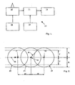
Figure 1 illustrates an outline of the components of a obstacle advisory system according to the present invention; -
Figure 2 illustrates the calculation of waypoints for a vehicle following a straight trajectory; -
Figure 3 illustrates the calculation of waypoints having an increased spacing for a vehicle following a straight trajectory; -
Figure 4 illustrates the subdivision of a zone into smaller zones for further analysis of whether or not the zone includes an obstacle; and -
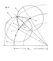
Figure 5 illustrates the calculation of waypoints for a helicopter following a curved trajectory. - Referring to
Figure 1 , an obstacleadvisory system 10 comprisesprocessors 11 operably connected to asensor 12, anavigational apparatus 13 and adisplay 14. In will be understood that theprocessor 11 receives inputs from thesensor 12 and thenavigational apparatus 13, whilst it provides an output to thedisplay 14 for viewing by an operator of a vehicle associated with the obstacleadvisory system 10. Thesensor 12 is operably connected to asensor controller 15 which governs the operation of thesensor 12 so as to produce data corresponding to obstacles, not illustrated, in the direction of motion of the vehicle. Theprocessor 11 analyses the data from thesensor 12 in accordance with a likely trajectory of the vehicle so as to determine whether or not an obstacle coincides with the likely trajectory of the vehicle. Information on possible collisions between the vehicle and an obstacle is indicated to the operator of the vehicle on thedisplay 14 so that the operator may take avoiding action. The determining of the likely trajectory is made from information supplied by thenavigation apparatus 13 to theprocessor 11 and theprocessor 11 determines possible collision of the vehicle with obstacles in the manner described below with reference toFigures 2 to 5 . The likely trajectory of the vehicle is determined from the velocity of the vehicle relative to earth, the velocity of the vehicle relative to air and the acceleration and the angles describing the motion of the vehicle. This information is supplied by thenavigation apparatus 13. - Referring to
Figure 2 , theobstacle advisory system 10 determines for a vehicle, not illustrated, the vehicle'slikely trajectory 16 andpossible waypoints likely trajectory 16. The predetermined intervals Δχ betweenpossible waypoints Figure 2 or likely to follow a curved trajectory as illustrated inFigure 3 . Thesystem 10 firstly determines whether or not thelikely trajectory 16 of the vehicle is straight or curved and dependent on this determination uses an associated equation to determine the distance Δχ betweenpossible waypoints likely trajectory 16. - The
system 10 uses information from the navigation apparatus in order to determine thelikely trajectory 16 of the vehicle based on the previous movement of the vehicle and the current speed and heading of the vehicle so as to extrapolate alikely trajectory 16 for the vehicle for a predetermined distance forward with respect to the motion of the vehicle's present position. - The
system 10 employs the following formula to determine whether or not thelikely trajectory 16 of the vehicle is straight or curved:
where RCurve is the radius of the curved trajectory. Min. Velocity is the minimum determined velocity of the vehicle over a predetermined time period and Max. Acceleration is the maximum determined centripetal acceleration of the vehicle over a predetermined time period. If the result of this formula tends to infinite then thelikely trajectory 16 of the vehicle is straight, otherwise thelikely trajectory 16 of the vehicle is curved. - If it is first assumed that the
likely trajectory 16 has been determined to be straight, then referring toFigure 2 and using the following formula it is possible to determine the interval Δχ between eachpossible waypoint 
where Δχ is the interval betweenpossible waypoints spherical region
It will noted fromFigure 2 that thespherical region 
The analysis of a conflict between thespherical region sensor 15 in determining whether or not aspherical region - Once the
possible waypoints likely trajectory 16, then analysis is undertaken by theprocessor 11 to determine whether or not aspherical region possible waypoint spherical region processor 11 can disregard the area enclosed by thespherical region processor 11. - If a
spherical region spherical region Figure 3 . In this example the radius R is increase by a factor of two. Therefore, if it is assumed that thelikely trajectory 16 of the vehicle has been determined to be straight as previously described, then for the present example the formula used to determine the interval Δχ' between each possible waypoint 17', 18' and 19' along thelikely trajectory 16 is now:
- Accordingly, the
processor 11 determines new waypoints 17', 18' and 19' having a greater spacing Δχ' than previously described with reference toFigure 2 and the associated spherical regions 20', 21' and 22' enclose a greater volume around the waypoint 17', 18' and 19'. In this manner, should an initialspherical region processor 11 can decide to use a larger spherical region 20', 21' or 22'. It will be understood that the spherical regions 20', 21' and 22' can be expanded by any suitable factor until a spherical region 20', 21' or 22' includes an obstacle. - Referring to
Figure 4 , should thespherical region Figure 2 include an obstacle, theprocessor 11 subdivides thespherical region spherical regions spherical region waypoint likely trajectory 16 of the vehicle. Therefore, if it is assumed that thelikely trajectory 16 of the vehicle has been determined to be straight as previously described, then for the present example the formula used to determine the interval Δχ" between eachpossible waypoint likely trajectory 16 is:
possible waypoints spherical region
Accordingly, theprocessor 11 determinesnew waypoints Figure 2 and the associatedspherical regions respective waypoint spherical region processor 11 can decide to use a smallerspherical region spherical regions spherical regions - In this manner, only those spherical regions which initially include an obstacle are further examined by dividing the spherical region into reduced spherical regions and again determining for each reduced spherical region whether or not that region still includes an obstacle. Those spherical regions that do not include an obstacle are no longer considered candidates for further division and selection. Accordingly, processing time for the
system 10 is reduced by focusing on only those spherical regions that include an obstacle. - Previously in the description with reference to
Figures 2 to 4 it has been assumed that the likely trajectory of the vehicle will follow a straight line, but it is possible that the processor may determine that the likely trajectory will follow a curved path. Referring toFigure 5 , theobstacle advisory system 10 determines for a vehicle, not illustrated, the vehicleslikely trajectory 50 andpossible waypoints likely trajectory 50. The predetermined intervals Δχ betweenpossible waypoints system 10 uses information from thenavigation apparatus 13 in order to determine thelikely trajectory 50 of the vehicle based on the previous movement of the vehicle and the current speed and heading of the vehicle so as to extrapolate alikely trajectory 50 for the vehicle for a predetermined distance forward with respect to the motion of the vehicles present position.
Should theprocessor 11 predict that the vehicle is likely to follow a curved trajectory then referring toFigure 5 and using the following formula it is possible to determine the interval Δχ between each possible waypoint:
- The determination as to whether or not the an obstacle is included in a
spherical region possible waypoints spherical region Figures 2 to 4 .
Claims (26)
- An obstacle advisory system (10) for a vehicle, comprising
means (13) for determining the likely trajectory (16) of the vehicle,
means (13) for determining possible waypoints (17;18;19) along the likely trajectory (16) of the vehicle at predetermined intervals between possible waypoints, and
means (11) for determining whether or not a predetermined zone (20;21;22) around a possible waypoint (17;18;19) includes an obstacle,
characterized in that it further comprises
means (11) for subdividing the predetermined zone (20;21) into reduced zones (20a;20b;21a;21b) which are intersected by the likely trajectory (16) should the predetermined zone (20;21) include an obstacle,
means (11) for determining for each reduced zone (20a,20b;21a,21b) whether or not that reduced zone includes an obstacle, and
means (11), for selecting each reduced zone which includes an obstacle for further subdivision and further selection until the reduced zones become a predetermined minimum size. - An obstacle advisory system, as in Claim 1, including means (11) for determining an increased zone (20';21';22') by increasing the predetermined zone (20;21;22) by a predetermined factor should the predetermined zone not include an obstacle, and means for determining whether or not an increased zone (20';21';22';) includes an obstacle.
- An obstacle advisory system, as in Claim 2, wherein the predetermined zone (20;21;22) is increased by a predetermined factor until the increased zone includes an obstacle.
- An obstacle advisory system, as in Claim 3, including means (11) for subdividing the increased zone (20';21') into reduced zones (20a;20b;21a,21b), should the increased zone include an obstacle, and means for determining for each reduced zone whether or not that reduced zone includes an obstacle and means for selecting each reduced zone which includes an obstacle for further subdivision and further selection until the reduced zones become a predetermined minimum size.
- An obstacle advisory system, as in any preceding claim, wherein each predetermined zone is defined by a spherical region (20;21;22) having a predetermined radius (2R) and the spherical region (20;21;22) is centred around its respective possible waypoint (17;18;19).
- An obstacle advisory system, as in any preceding claim, wherein the reduced zones are defined by reduced spherical regions (20a,20b;21a,21b) having predetermined radii (R) and each reduced spherical region is centred around an intermediate point (17a,17b;18a,18b) between possible waypoints (17;18) and along the likely trajectory (16) of the vehicle.
- An obstacle advisory system, as in Claim 6, wherein the spherical region (20;21;22) and reduced spherical regions (20a,20b,21a,21b) are reduced by reducing the radius (2R) of each spherical region (20;21;22).
- An obstacle advisory system, as in Claim 7, wherein the radius (2R) of the spherical region (20;21;22) and reduced spherical regions (20a,20b;21a,21b) are reduced by a factor of two.
- An obstacle advisory system, as in Claims 2 to 8, wherein the increased zones are defined by increased spherical regions (20';21';22') having predetermined radii (2R) and each increased spherical region (20';21';22') are centred around its respective possible waypoint (17';18';19')
- An obstacle advisory system, as in Claims 5 to 9, wherein the spherical region (20;21;22) and increased spherical regions (20';21';22') are increased by increasing the radius (2R) of each spherical region (20;21;22).
- An obstacle advisory system, as in Claim 10, wherein the radius of the spherical region (20;21;22) and the increased spherical regions (20';21';22') are increased by a factor of two.
- An obstacle advisory system, as in any preceding claim, wherein the predetermined minimum size of the reduced zones (20a,20b;21a,21b) are substantially equal in volume to that of the vehicle.
- An obstacle advisory system, as in Claims 1 to 11, wherein the predetermined minimum size of the reduced zones (20a,20b;21a;21b) are substantially equal in volume to that of the vehicle and an additional error margin.
- An obstacle advisory system, as in Claim 13, wherein the additional error margin is related to the detection error of the means for determining whether or not a zone (20;21;22) around a waypoint (17;18;19) includes an obstacle.
- An obstacle advisory system, as in any preceding claim, wherein the means for determining whether or not a zone (20;21;22) around a waypoint (17;18;19) includes an obstacle is a laser radar apparatus.
- An obstacle advisory system, as in any preceding claim, wherein waypoints (17;18;19) are substantially equally spaced along the likely trajectory (16) of the vehicle at intervals substantially equal to the radius (2R) of a spherical region (20;21;22) enclosing the vehicle.
- An obstacle advisory system, as in Claims 1 to 16, wherein possible waypoints (17;18;19) are substantially equally spaced along the likely trajectory (16) of the vehicle at intervals substantially equal to the radius (2R) of a spherical region (20;21;22) enclosing the vehicle and an additional error margin which is related to the detection error of the means for determining whether or not a zone (20;21;22) around a possible waypoint (17;18;19) includes an obstacle.
- An obstacle advisory system, as in any preceding claim, wherein the means (15) for determining the likely trajectory (16) of the vehicle are also adapted to determine whether the likely trajectory (16) is straight or curved.
- An obstacle advisory system, as in Claim 18, wherein the means (13) for determining whether or not the likely trajectory (16) of the vehicle is curved is determined by the formula:
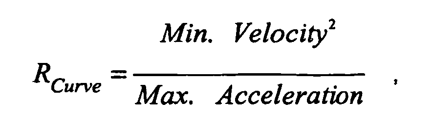
where RCurve is the radius of the curved trajectory, Min. Velocity is the minimum determined velocity of the vehicle over a predetermined time period and Max. Acceleration is the maximum determined centripetal acceleration of the vehicle over a predetermined time period. - An obstacle advisory system, as in Claim 5 to 19, wherein the predetermined interval between possible waypoints (17; 18; 19) on a straight likely trajectory (16) is determined from the formula:

where Δχ is the interval between possible waypoints (17; 18; 19), R is the radius of the spherical region (20; 21; 22) and y is the radius of the vehicle. - An obstacle advisory system, as in Claims 5 to 19, wherein the predetermined interval between possible waypoints (17; 18; 19) on a curved likely trajectory (16) is determined from the formula:

where Δχ is the interval between possible waypoints (17; 18; 19), R is the radius of the spherical region (20; 21; 22), RCurve is the radius of the curved trajectory (16) and y is radius of the vehicle. - An obstacle advisory system, as in any preceding claim, wherein the vehicle is an aircraft.
- An obstacle advisory system, as in any preceding claim, wherein the vehicle is a road vehicle.
- An obstacle advisory system, as in any preceding claim, wherein the vehicle is a marine vessel.
- An obstacle advisory system, as in any preceding claim, including a display means for conveying an indication of at least one obstacle and the position of the obstacle relative to the vehicle.
- A method of detecting obstacles, including
determining the likely trajectory (16) of a vehicle,
determining possible waypoints (17;18;19) along the likely trajectory (16) of the vehicle at predetermined intervals between possible waypoints (17;18;19), and
determining whether or not a predetermined zone (20;21;22) around a possible waypoint (17;18;19) includes an obstacle, characterized in that it further includes.
should the predetermined zone (20;21) include an obstacle, subdividing the predetermined zone (20;21) into reduced zone (20a,20b;21a,21b) which are intersected by the likely trajectory (16),
determining for each reduced zone (20a,20b;21a,21b) whether or not that reduced zone includes an obstacle, and
selecting each reduced zone which includes an obstacle for further subdivision and further selection until the reduced zones become a predetermined minimum size.
Applications Claiming Priority (2)
| Application Number | Priority Date | Filing Date | Title |
|---|---|---|---|
| ITTO20010546 | 2001-06-06 | ||
| IT2001TO000546A ITTO20010546A1 (en) | 2001-06-06 | 2001-06-06 | REFINEMENTS RELATING TO ADVISORY SYSTEMS FOR THE PRESENCE OF OBSTACLES. |
Publications (3)
| Publication Number | Publication Date |
|---|---|
| EP1265078A2 EP1265078A2 (en) | 2002-12-11 |
| EP1265078A3 EP1265078A3 (en) | 2005-07-06 |
| EP1265078B1 true EP1265078B1 (en) | 2009-07-08 |
Family
ID=11458935
Family Applications (1)
| Application Number | Title | Priority Date | Filing Date |
|---|---|---|---|
| EP02253269A Expired - Lifetime EP1265078B1 (en) | 2001-06-06 | 2002-05-09 | Improvements in or relating to obstacle advisory systems and methods |
Country Status (7)
| Country | Link |
|---|---|
| EP (1) | EP1265078B1 (en) |
| AT (1) | ATE436031T1 (en) |
| DE (1) | DE60232838D1 (en) |
| DK (1) | DK1265078T3 (en) |
| ES (1) | ES2329660T3 (en) |
| IT (1) | ITTO20010546A1 (en) |
| PT (1) | PT1265078E (en) |
Families Citing this family (4)
| Publication number | Priority date | Publication date | Assignee | Title |
|---|---|---|---|---|
| DE10255797A1 (en) * | 2002-11-28 | 2004-06-17 | Daimlerchrysler Ag | A method for detecting the forward environment of a road vehicle by means of an environment detection system |
| GB2577915B (en) * | 2018-10-10 | 2021-06-16 | Dyson Technology Ltd | Path planning |
| CN110189547B (en) * | 2019-05-30 | 2020-10-20 | 广州小鹏汽车科技有限公司 | An obstacle detection method, device and vehicle |
| CN120886273B (en) * | 2025-09-29 | 2026-01-06 | 北京大学南昌创新研究院 | A humanoid robot fusion system with autonomous navigation |
Family Cites Families (4)
| Publication number | Priority date | Publication date | Assignee | Title |
|---|---|---|---|---|
| US4751658A (en) * | 1986-05-16 | 1988-06-14 | Denning Mobile Robotics, Inc. | Obstacle avoidance system |
| US5390125A (en) * | 1990-02-05 | 1995-02-14 | Caterpillar Inc. | Vehicle position determination system and method |
| EP0592436A1 (en) * | 1990-10-09 | 1994-04-20 | PILLEY, Harold R. | Airport control/management system |
| TW440688B (en) * | 1999-06-30 | 2001-06-16 | Gia Min Chung | A path planning, terrain avoidance and situation awareness system for general aviation |
-
2001
- 2001-06-06 IT IT2001TO000546A patent/ITTO20010546A1/en unknown
-
2002
- 2002-05-09 PT PT02253269T patent/PT1265078E/en unknown
- 2002-05-09 DE DE60232838T patent/DE60232838D1/en not_active Expired - Lifetime
- 2002-05-09 AT AT02253269T patent/ATE436031T1/en not_active IP Right Cessation
- 2002-05-09 ES ES02253269T patent/ES2329660T3/en not_active Expired - Lifetime
- 2002-05-09 DK DK02253269T patent/DK1265078T3/en active
- 2002-05-09 EP EP02253269A patent/EP1265078B1/en not_active Expired - Lifetime
Also Published As
| Publication number | Publication date |
|---|---|
| ATE436031T1 (en) | 2009-07-15 |
| DK1265078T3 (en) | 2009-09-07 |
| EP1265078A2 (en) | 2002-12-11 |
| ITTO20010546A1 (en) | 2002-12-06 |
| DE60232838D1 (en) | 2009-08-20 |
| PT1265078E (en) | 2009-07-20 |
| ITTO20010546A0 (en) | 2001-06-06 |
| EP1265078A3 (en) | 2005-07-06 |
| ES2329660T3 (en) | 2009-11-30 |
Similar Documents
| Publication | Publication Date | Title |
|---|---|---|
| US11898855B2 (en) | Assistance control system that prioritizes route candidates based on unsuitable sections thereof | |
| US6097996A (en) | Method for the lateral avoidance of a mobile zone by a vehicle | |
| EP1151244B1 (en) | Ground proximity warning system | |
| KR101736977B1 (en) | Control and systems for autonomously driven vehicles | |
| US6201482B1 (en) | Method of detecting a collision risk and preventing air collisions | |
| US6538581B2 (en) | Apparatus for indicating air traffic and terrain collision threat to an aircraft | |
| EP0836074B1 (en) | Route guidance system and method for use in vehicle navigation | |
| US5892462A (en) | Adaptive ground collision avoidance system | |
| US6792363B1 (en) | System and method for trajectory optimization using adaptive navigation performance estimation | |
| US20060235610A1 (en) | Map-based trajectory generation | |
| EP1832850B1 (en) | Sytstems and methods for selectively altering a ground proximity message | |
| US20020152029A1 (en) | Method for working out an avoidance path in the horizontal plane for an aircraft to resolve a traffic conflict | |
| EP0933615B1 (en) | Route searching apparatus | |
| EP4222035B1 (en) | Methods and systems for performing outlet inference by an autonomous vehicle to determine feasible paths through an intersection | |
| CN102591352B (en) | Method and device for assisting with the visual assessment of a flight path to be followed by an aircraft in a restricted environment | |
| US20210114625A1 (en) | System and method for autonomous collision avoidance | |
| EP0543543A1 (en) | Location detecting apparatus with overspeed predicting means | |
| WO2022154995A1 (en) | Methods and system for constructing data representation for use in assisting autonomous vehicles navigate intersections | |
| EP1770365B1 (en) | Method for planning the velocity of a craft along a route | |
| US11358598B2 (en) | Methods and systems for performing outlet inference by an autonomous vehicle to determine feasible paths through an intersection | |
| EP3699645B1 (en) | Systems and methods for vehicle navigation | |
| CN1184991A (en) | Method for guiding driver by predicting progress path of car | |
| EP1476719B1 (en) | Method and system for calculating a flight route | |
| EP1265078A2 (en) | Improvements in or relating to obstacle advisory systems | |
| CN113218410A (en) | System and method for vehicle navigation using terrain text recognition |
Legal Events
| Date | Code | Title | Description |
|---|---|---|---|
| PUAI | Public reference made under article 153(3) epc to a published international application that has entered the european phase |
Free format text: ORIGINAL CODE: 0009012 |
|
| AK | Designated contracting states |
Kind code of ref document: A2 Designated state(s): AT BE CH CY DE DK ES FI FR GB GR IE IT LI LU MC NL PT SE TR |
|
| AX | Request for extension of the european patent |
Free format text: AL;LT;LV;MK;RO;SI |
|
| PUAL | Search report despatched |
Free format text: ORIGINAL CODE: 0009013 |
|
| AK | Designated contracting states |
Kind code of ref document: A3 Designated state(s): AT BE CH CY DE DK ES FI FR GB GR IE IT LI LU MC NL PT SE TR |
|
| AX | Request for extension of the european patent |
Extension state: AL LT LV MK RO SI |
|
| 17P | Request for examination filed |
Effective date: 20051215 |
|
| AKX | Designation fees paid |
Designated state(s): AT BE CH CY DE DK ES FI FR GB GR IE IT LI LU MC NL PT SE TR |
|
| 17Q | First examination report despatched |
Effective date: 20080204 |
|
| GRAP | Despatch of communication of intention to grant a patent |
Free format text: ORIGINAL CODE: EPIDOSNIGR1 |
|
| RTI1 | Title (correction) |
Free format text: IMPROVEMENTS IN OR RELATING TO OBSTACLE ADVISORY SYSTEMS AND METHODS |
|
| RAP1 | Party data changed (applicant data changed or rights of an application transferred) |
Owner name: SELEX COMMUNICATIONS S.P.A. |
|
| GRAS | Grant fee paid |
Free format text: ORIGINAL CODE: EPIDOSNIGR3 |
|
| GRAA | (expected) grant |
Free format text: ORIGINAL CODE: 0009210 |
|
| AK | Designated contracting states |
Kind code of ref document: B1 Designated state(s): AT BE CH CY DE DK ES FI FR GB GR IE IT LI LU MC NL PT SE TR |
|
| REG | Reference to a national code |
Ref country code: GB Ref legal event code: FG4D |
|
| REG | Reference to a national code |
Ref country code: CH Ref legal event code: NV Representative=s name: JACOBACCI & PARTNERS S.P.A. Ref country code: CH Ref legal event code: EP |
|
| REG | Reference to a national code |
Ref country code: PT Ref legal event code: SC4A Free format text: AVAILABILITY OF NATIONAL TRANSLATION Effective date: 20090708 |
|
| REG | Reference to a national code |
Ref country code: IE Ref legal event code: FG4D |
|
| REF | Corresponds to: |
Ref document number: 60232838 Country of ref document: DE Date of ref document: 20090820 Kind code of ref document: P |
|
| REG | Reference to a national code |
Ref country code: DK Ref legal event code: T3 |
|
| REG | Reference to a national code |
Ref country code: GR Ref legal event code: EP Ref document number: 20090402177 Country of ref document: GR |
|
| REG | Reference to a national code |
Ref country code: SE Ref legal event code: TRGR |
|
| REG | Reference to a national code |
Ref country code: ES Ref legal event code: FG2A Ref document number: 2329660 Country of ref document: ES Kind code of ref document: T3 |
|
| PG25 | Lapsed in a contracting state [announced via postgrant information from national office to epo] |
Ref country code: AT Free format text: LAPSE BECAUSE OF FAILURE TO SUBMIT A TRANSLATION OF THE DESCRIPTION OR TO PAY THE FEE WITHIN THE PRESCRIBED TIME-LIMIT Effective date: 20090708 |
|
| PLBE | No opposition filed within time limit |
Free format text: ORIGINAL CODE: 0009261 |
|
| STAA | Information on the status of an ep patent application or granted ep patent |
Free format text: STATUS: NO OPPOSITION FILED WITHIN TIME LIMIT |
|
| PG25 | Lapsed in a contracting state [announced via postgrant information from national office to epo] |
Ref country code: BE Free format text: LAPSE BECAUSE OF FAILURE TO SUBMIT A TRANSLATION OF THE DESCRIPTION OR TO PAY THE FEE WITHIN THE PRESCRIBED TIME-LIMIT Effective date: 20090708 |
|
| 26N | No opposition filed |
Effective date: 20100409 |
|
| PG25 | Lapsed in a contracting state [announced via postgrant information from national office to epo] |
Ref country code: MC Free format text: LAPSE BECAUSE OF NON-PAYMENT OF DUE FEES Effective date: 20100531 |
|
| PG25 | Lapsed in a contracting state [announced via postgrant information from national office to epo] |
Ref country code: CY Free format text: LAPSE BECAUSE OF FAILURE TO SUBMIT A TRANSLATION OF THE DESCRIPTION OR TO PAY THE FEE WITHIN THE PRESCRIBED TIME-LIMIT Effective date: 20090708 |
|
| PG25 | Lapsed in a contracting state [announced via postgrant information from national office to epo] |
Ref country code: LU Free format text: LAPSE BECAUSE OF NON-PAYMENT OF DUE FEES Effective date: 20100509 |
|
| REG | Reference to a national code |
Ref country code: CH Ref legal event code: PCAR Free format text: NEW ADDRESS: VIA LUGANETTO 3, 6962 LUGANO (CH) |
|
| REG | Reference to a national code |
Ref country code: FR Ref legal event code: PLFP Year of fee payment: 15 |
|
| REG | Reference to a national code |
Ref country code: FR Ref legal event code: PLFP Year of fee payment: 16 |
|
| REG | Reference to a national code |
Ref country code: FR Ref legal event code: PLFP Year of fee payment: 17 |
|
| PGFP | Annual fee paid to national office [announced via postgrant information from national office to epo] |
Ref country code: DE Payment date: 20210527 Year of fee payment: 20 Ref country code: FR Payment date: 20210525 Year of fee payment: 20 Ref country code: FI Payment date: 20210527 Year of fee payment: 20 Ref country code: GR Payment date: 20210527 Year of fee payment: 20 Ref country code: IT Payment date: 20210524 Year of fee payment: 20 Ref country code: NL Payment date: 20210526 Year of fee payment: 20 Ref country code: PT Payment date: 20210423 Year of fee payment: 20 |
|
| PGFP | Annual fee paid to national office [announced via postgrant information from national office to epo] |
Ref country code: TR Payment date: 20210428 Year of fee payment: 20 Ref country code: SE Payment date: 20210527 Year of fee payment: 20 Ref country code: IE Payment date: 20210527 Year of fee payment: 20 Ref country code: CH Payment date: 20210527 Year of fee payment: 20 Ref country code: ES Payment date: 20210601 Year of fee payment: 20 Ref country code: DK Payment date: 20210527 Year of fee payment: 20 Ref country code: GB Payment date: 20210527 Year of fee payment: 20 |
|
| REG | Reference to a national code |
Ref country code: DE Ref legal event code: R071 Ref document number: 60232838 Country of ref document: DE |
|
| REG | Reference to a national code |
Ref country code: NL Ref legal event code: MK Effective date: 20220508 |
|
| REG | Reference to a national code |
Ref country code: CH Ref legal event code: PL |
|
| REG | Reference to a national code |
Ref country code: DK Ref legal event code: EUP Expiry date: 20220509 |
|
| REG | Reference to a national code |
Ref country code: GB Ref legal event code: PE20 Expiry date: 20220508 |
|
| REG | Reference to a national code |
Ref country code: IE Ref legal event code: MK9A |
|
| REG | Reference to a national code |
Ref country code: FI Ref legal event code: MAE |
|
| PG25 | Lapsed in a contracting state [announced via postgrant information from national office to epo] |
Ref country code: PT Free format text: LAPSE BECAUSE OF EXPIRATION OF PROTECTION Effective date: 20220518 Ref country code: IE Free format text: LAPSE BECAUSE OF EXPIRATION OF PROTECTION Effective date: 20220509 Ref country code: GB Free format text: LAPSE BECAUSE OF EXPIRATION OF PROTECTION Effective date: 20220508 |
|
| REG | Reference to a national code |
Ref country code: ES Ref legal event code: FD2A Effective date: 20220902 |
|
| PG25 | Lapsed in a contracting state [announced via postgrant information from national office to epo] |
Ref country code: ES Free format text: LAPSE BECAUSE OF EXPIRATION OF PROTECTION Effective date: 20220510 |