EP1265053A1 - Diagnostic test for a resonant micro electro mechanical angular rate system - Google Patents
Diagnostic test for a resonant micro electro mechanical angular rate system Download PDFInfo
- Publication number
- EP1265053A1 EP1265053A1 EP02011689A EP02011689A EP1265053A1 EP 1265053 A1 EP1265053 A1 EP 1265053A1 EP 02011689 A EP02011689 A EP 02011689A EP 02011689 A EP02011689 A EP 02011689A EP 1265053 A1 EP1265053 A1 EP 1265053A1
- Authority
- EP
- European Patent Office
- Prior art keywords
- signal
- output signal
- test
- feedback control
- sensor element
- Prior art date
- Legal status (The legal status is an assumption and is not a legal conclusion. Google has not performed a legal analysis and makes no representation as to the accuracy of the status listed.)
- Withdrawn
Links
- 238000002405 diagnostic procedure Methods 0.000 title description 3
- 238000012360 testing method Methods 0.000 claims abstract description 89
- 238000000034 method Methods 0.000 claims description 12
- 238000006073 displacement reaction Methods 0.000 abstract description 4
- 238000002347 injection Methods 0.000 abstract description 4
- 239000007924 injection Substances 0.000 abstract description 4
- 230000002950 deficient Effects 0.000 abstract description 2
- 230000003750 conditioning effect Effects 0.000 description 10
- 238000001514 detection method Methods 0.000 description 10
- 238000010586 diagram Methods 0.000 description 9
- 230000000694 effects Effects 0.000 description 3
- 230000008901 benefit Effects 0.000 description 2
- 230000007257 malfunction Effects 0.000 description 2
- 230000010355 oscillation Effects 0.000 description 2
- 238000013459 approach Methods 0.000 description 1
- 239000000919 ceramic Substances 0.000 description 1
- 230000001143 conditioned effect Effects 0.000 description 1
- 238000007796 conventional method Methods 0.000 description 1
- 238000011161 development Methods 0.000 description 1
- -1 for example Substances 0.000 description 1
- 238000011990 functional testing Methods 0.000 description 1
- 230000010354 integration Effects 0.000 description 1
- 239000000463 material Substances 0.000 description 1
- 238000004377 microelectronic Methods 0.000 description 1
- 238000005459 micromachining Methods 0.000 description 1
- 239000010453 quartz Substances 0.000 description 1
- 229910052710 silicon Inorganic materials 0.000 description 1
- 239000010703 silicon Substances 0.000 description 1
- VYPSYNLAJGMNEJ-UHFFFAOYSA-N silicon dioxide Inorganic materials O=[Si]=O VYPSYNLAJGMNEJ-UHFFFAOYSA-N 0.000 description 1
- 238000010998 test method Methods 0.000 description 1
Images


Classifications
-
- G—PHYSICS
- G01—MEASURING; TESTING
- G01C—MEASURING DISTANCES, LEVELS OR BEARINGS; SURVEYING; NAVIGATION; GYROSCOPIC INSTRUMENTS; PHOTOGRAMMETRY OR VIDEOGRAMMETRY
- G01C19/00—Gyroscopes; Turn-sensitive devices using vibrating masses; Turn-sensitive devices without moving masses; Measuring angular rate using gyroscopic effects
- G01C19/56—Turn-sensitive devices using vibrating masses, e.g. vibratory angular rate sensors based on Coriolis forces
- G01C19/5607—Turn-sensitive devices using vibrating masses, e.g. vibratory angular rate sensors based on Coriolis forces using vibrating tuning forks
-
- G—PHYSICS
- G01—MEASURING; TESTING
- G01C—MEASURING DISTANCES, LEVELS OR BEARINGS; SURVEYING; NAVIGATION; GYROSCOPIC INSTRUMENTS; PHOTOGRAMMETRY OR VIDEOGRAMMETRY
- G01C25/00—Manufacturing, calibrating, cleaning, or repairing instruments or devices referred to in the other groups of this subclass
Definitions
- This invention relates in general to angular rate sensors and in particular to an apparatus and a method for performing a diagnostic test upon an angular rate sensor.
- Angular rate sensors are widely used in many commercial applications, such as, for example, attitude control systems for automobiles, a gyroscope for a navigation system included in a moving object or a hand-shake compensating system for video cameras.
- Angular rate sensors measure the rate of rotation of a body about its three principle axes. The rotational movement is typically referred to as yaw, pitch and roll which are related to vertical, transverse and longitudinal axes, respectively.
- a simplified angular rate sensor element 10 is illustrated in Figs. 1 and 2 as tuning fork.
- Such sensors typically include a pair of vibrating elements, that are shown as tines 11 and 12 in Fig. 1.
- the lower ends of the tines 11 and 12 are connected by an output shaft 13.
- the tines 11 and 12, which function as proof masses, are driven in opposite directions in the plane of the drawing by electrostatic drive motors 14 and 15.
- the tines 11 and 12 vibrate in the directions shown by the small arrows labeled 16 and 17.
- angular rate sensors When an angular rate, illustrated by the circular arrow 18, is applied to the sensor element 10 about an axis 19 in the plane of the sensor element 10, the tines 11 and 12 are caused to oscillate out of the plane by a Coriolos force due to Coriolos effect, as shown in Fig. 2 by the small arrows labeled 20 and 21.
- the resulting out-of plane oscillation motion amplitude which is proportional to the input angular rate, is detected and measured by capacitive or electrostatic pickoff plates 22 that are located adjacent to the upper ends of the tines 11 and 12. While a simplified sensor element 10 has been shown in Figs. 1 and 2 it will be appreciated that angular rate sensors typically include one, two, four or any plurality of tuning forks in a unitary system.
- MEMS Micro Electro Mechanical System
- FIG. 3 A schematic diagram for a typical MEMS angular rate sensor 23 is illustrated in Fig. 3. Components shown in Fig. 3 that are similar to components shown in Figs. 1 and 2 have the same numerical identifiers. Additional capacitive or electrostatic pickoff plates 24 and 25 have been added to measure amplitude and frequency of the oscillation of the tines 11 and 12 within the plane of the sense element 10. The information obtained from pickoff plates 24 and 25 is fed back through the lines labeled 28 and 29 to a closed loop sense element drive circuit 30. While the lines 28 and 29 are shown as single wires, it will be appreciated that the circuit has been simplified for clarity and that multiple wires or traces may actually be used.
- the sense element drive circuit 26 is conventional and typically includes an oscillator with automatic gain and frequency control (not shown) that receives the feedback from the pickoff plates 24 and 25 to assure that the linear motion is provided to sense element 10.
- Sense element drive signals are supplied to the electrostatic drive motors 14 and 15 by the output lines 28A and 29A.
- Analog data from the Coriolos force pickoff plates 22 is supplied through the lines labeled 32 and 34 to an open loop signal conditioning circuit 36. While the lines 32 and 34 are shown as single wires, it will appreciated that the drive circuit has been simplified for clarity and that multiple wires or traces may actually be used.
- the signal conditioning circuit 36 generates an output signal that is proportional to the angular rate on an output line 38.
- the output signal may be either an analog or a digital signal.
- the output line 38 is connected to an input port of a microprocessor (not shown).
- a block diagram 40 for a typical signal conditioning circuit 36 is illustrated in Fig. 4. Additionally, the sense element 10 is shown in block form. Thus, an input angular rate ⁇ in is applied to a proof mass, m, or the tines 11 and 12 in the illustrative example, in block 42.
- the proof mass m responds to the angular rate ⁇ in with an input force F in that is applied to the sense elements, or the Coriolos force pickoff plates 22, in block 44.
- the input force F in is converted to voltage, V, in block 46 and supplied to the signal conditioning circuit 36.
- the voltage V is amplified and any offset is cancelled in block 48.
- the amplified signal is filtered in block 50 and then converted to a digital signal by a quantizer in block 52.
- the output of the filter in block 50 can be directly used as an analog signal, in which case the quantizer in block 52 is omitted from Fig. 4.
- the output of the filter block 50 is supplied directly as an analog signal to an analog input pin 53 of an Electronic Control Unit (ECU) 54.
- the ECU 54 has a test output pin 55 that is connected to a test signal generator 56.
- the test signal generator 56 generates an analog test signal when the ECU output pin 55 changes state, such as, for example, goes from zero voltage to a high value, which is typically five volts.
- the analog test signal is injected at point 57 to the input of the signal conditioning circuit 36.
- the resulting analog output signal is converted to a digital output signal by an analog to digital converter 58 within the ECU 54.
- the digital output signal is supplied to a comparator 59 that compares the output signal value to an expected value that corresponds to the test signal. If the output signal value is different from the expected value, an error flag is set to indicate that the signal conditioning circuit is malfunctioning. Alternately, the difference between the output signal and the expected value are compared to a predetermined threshold. If the difference exceeds the threshold, the error flag is set. While the test signal generator 56 is shown in Fig. 5 as a separate component, it will be appreciated that the circuit can be included in the ECU 54 (not shown).
- This invention relates to an apparatus and a method for performing a diagnostic test upon a angular rate sensor.
- the present invention contemplates a device for measuring a angular rate comprising a sensor element with a first feedback control device connected to the sensor element, the first feedback control device operative to resonate the sensor element.
- the device also includes a second feedback control device connected to the sensor element, the second feedback control device operative to sense the presence of a secondary mode signal generated by the sensor element in response to a Coriolis force and to generate a null signal that cancels said secondary mode signal.
- the second feedback control device also generates an output signal that is proportional to the null signal.
- the angular rate measuring device further includes a test device connected to the second feedback control device, the test device being operative to inject a test signal into the second feedback loop such that the test signal is passed through the sense element. Accordingly, the output signal will be proportional to the test signal.
- the test device is further operative to compare the resulting output signal to the previous output signal and to set an error flag if the output signal has not changed as a result of the injection of the test signal. The test device also sets an error flag if the resulting output signal exceeds a first predetermined threshold or if the change in the output signal exceeds a second predetermined threshold.
- the invention also contemplates a method for testing an angular rate measuring device comprising the steps of providing a sensor element and a first feedback control device connected to the sensor element.
- the first feedback control device is operative to resonate the sensor element.
- the angular rate measuring device also includes a second feedback control device connected to the sensor element.
- the second feedback control device is operative to sense the presence of a secondary mode signal generated by the sensor element in response to a Coriolis force and to generate a null signal that cancels the secondary mode signal.
- the second feedback control device also generates an output signal that is proportional to the null signal.
- the method includes first resonating the sensor element and subsequently injecting a test signal into the second feedback control device that is passed through the sense element. Accordingly, the output signal is proportional to the test signal. The method then compares the resulting output signal to the preceding output signal and sets an flag if the output signal has not changed in response to the test signal. Additionally, an error flag is set if the output signal resulting from the test signal exceeds a first determined threshold or if the change in the output signal exceeds a second predetermined threshold.
- a balanced resonant MEMS angular rate sensor 60 that uses a first closed loop control to drive the sense element of an angular rate sensor into resonance and a second closed loop control for detecting the effects of Coriolis force.
- the sense element 10 is shown as a simple tuning fork for clarity; however, it will be appreciated that other conventional structures can be utilized for the sense element.
- the sensor 60 is included in a Vehicle Stability Control (VSC) System to measure vehicle yaw about one of the principle vehicle axes.
- VSC System Vehicle Stability Control
- the VSC System is responsive to the angular rate and other signals to selectively actuate vehicle wheel brakes and the engine controls to correct undesired vehicle motion.
- the sensor 60 also can be utilized in other systems to measure angular rates.
- the closed loop drive for causing the sense element tines 11 and 12 to oscillate within the plane of the sense element 10 is the same as described above.
- the sensor 60 also includes a second closed loop balancing control circuit 62 that receives the Corilolis force induced signals from the Coriolos force pickoff plates 22.
- the balancing control circuit 62 uses conventional methods to generate a null signal that is applied through a feedback line 64 to null electrostatic drive motors 66, two of which are shown.
- null electrostatic drive motors 66 two of which are shown.
- another pair of null drive motors are positioned on the opposite surface of the tines 11 and 12. The null signal is sufficient to cause the null drive motors 66 to generate an opposite and equal force to the Coriolos force.
- the null drive motors 66 urge the tines 11 and 12 back into their original position while the null signal is proportional to the Coriolos force.
- the feedback balancing control circuit 62 functions as a second control loop of the sense element's detection drive.
- the null signal keeps the proof mass at near zero displacement in a detection plane that is perpendicular to the plane of the drawing.
- the null signal is supplied to a signal conditioning circuit 68 that further amplifies the signal and converts the signal into an output signal that appears on the output line 38.
- the balancing control circuit 62 cooperates with the signal conditioning circuit 68 to form a closed loop detection circuit.
- the output signal may be taken directly from the output of the balancing control circuit 62 (not shown), in which case, the balancing control circuit 62 becomes the closed loop detection circuit.
- the closed loop operation described above provides increased linearity of output since the displacement of the proof mass is kept small in the detection plane.
- the closed loop operation also increases the bandwidth of the sensor while reducing drift over time and temperature variations. In general, for precision applications, a balanced angular rate sensor provides better performance.
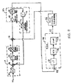
- the closed loop operation is further illustrated by the block diagram shown in Fig. 7.
- Components in Fig. 7 that are similar to components shown in Fig. 4 have the same numerical designators.
- the output signal from the balancing control circuit 62 can be further conditioned by a low pass filter in block 68; however, this step is optional. Additionally, other conventional signal conditioning circuitry can be included in block 68 (not shown).
- the analog output signal from the balancing control circuit 62 which is proportional to the Coriolos force, is inverted by block 70 and then applied to a transducer 72.
- the transducer 72 converts the signal voltage to a force that is applied to a summing point 74. Because the signal was inverted, the summing point 74 functions to null the force applied to the sense element 44.
- the output signal from the balancing control circuit 62 becomes the null signal.
- the present invention contemplates injecting a test signal at a second summing point 76, as illustrated in Fig. 8.
- Components that are similar to components shown in Fig. 5 have the same numerical designators.
- the optional low pass filter 68 shown in Fig. 7 has been included in the ECU 54.
- the test signal is generated by the test signal generator 56 in response to a request by the ECU 54.
- the test signal generator 56 generates an analog test signal that is injected at the second summing point 76 prior to the input of the signal feedback balancing control circuit 62. In this manner, the test signal injected at the sense element pick-off point 76 is equivalent to the secondary mode signal generated by a Coriolis force.
- the closed loop detection circuit is responsive to the test signal, in the same manner that it would be to a Coriolos force, to generate a feedback signal.
- the feedback signal is fed into the second feedback control loop of the sense element's detection drive. Therefore, second feedback control loop generates a null signal that is applied to the sense element in response to the injected test signal while the closed loop detection circuit produces an output signal that is proportional to the test signal.
- the resulting output signal from the balancing control signal circuit 62 is converted to a digital signal by the analog to digital convertor 58 and then supplied to the comparator 58.
- the comparator compares the output signal that corresponds to the test signal to the previous digital output signal. In the preferred embodiment, a change in the signal indicates that the sensor output is being nulled and thus that the sensor is functioning properly. Conversely, if the output signal does not change, it is an indication that the sense element and the associated circuits are malfunctioning. Accordingly, an error flag is set and the sensor is disabled. Alternately, the output signal must change in response to the test signal by an amount that exceeds a predetermined minimum to preclude setting the error flag.
- the output signal from the balancing control circuit that corresponds to the test signal is compared to a first predetermined threshold. If the output signal exceeds the first threshold, the error flag set.
- the threshold value is a function of the test signal. Alternately, the absolute value of the difference between the output signal resulting from the test signal and the previous output signal can be compared to a second predetermined threshold. If the difference exceeds the second threshold, it is an indication of a malfunction and the error flag is set.
- the second threshold can be a predetermined value to provide a margin of acceptable performance or the second threshold can be zero. While the test signal generator 56 is shown in Fig. 8 as a separate component, it will be appreciated that the circuit can be included in the ECU 54 (not shown).
- the test signal or artificial Coriolis force signal
- the second feedback control loop feeds into the second feedback control loop of the sense element's detection drive.
- the second feedback control loop then generates a null signal to cancel the injected test signal.
- this approach forces a physical response of the sense element 44, which makes it a 100% thorough self test. For example, if a wire bond between the sense element 44 and the signal conditioning circuit should fail, the failure would go undetected with the prior art method of testing since the test signal is injected "downstream" of the sense element. With the present invention, because the signal must pass through the sense element 44, any failure associated with the sense element would be detected.
- the invention further contemplates a test algorithm that is illustrated by the flow chart shown in Fig. 9.
- the test algorithm is shown for a balanced resonant angular rate sensor 60 that uses a first closed loop control to drive the sense element of a angular rate sensor into resonance and a second closed loop control for detecting the effects of Coriolis force.
- the sensor is included in a Vehicle Stability Control (VSC) System.
- VSC Vehicle Stability Control
- the algorithm is entered through block 90.
- the MEMS sensing element is resonated by the sense element drive circuit 30.
- an artificial test signal is injected into the closed loop control circuit that rebalances any Coriolis force that is acting upon the sense element.
- the artificial test signal is interpreted as a secondary mode signal, caused by Coriolis force.
- a null signal is generated by closed loop detection circuit and driven through the sense element to cancel the secondary mode signal caused by the test signal. If the sense element and associated circuitry are working properly, an output signal that is proportional to the test signal will be generated.
- decision block 98 the output signal generated in response to the test signal is compared to the previous output signal. If the output signal has changed, the sense element and associated circuitry is working properly and the algorithm exits through block 102.
- the test described above requires that the output signal remain unchanged to preclude setting an error flag, that is, the difference between the output signals before and after injection of the test signal is zero.
- the invention also contemplates an alternative embodiment in which the error flag is set if the change in the output signal due to the injection of the test signal is less than a predetermined minimum (not shown).
- the alternate embodiment allows a range of output values to trigger the error flag.
- the test signal is a fixed offset that is about half of the full scale output of the sensor. Accordingly, a change in the output signal will be readily apparent if the sensor is not functioning properly.
- the invention also contemplates an alternate embodiment that is illustrated by the flow chart shown in Fig. 10.
- blocks shown in Fig. 10 that are the same as blocks shown in Fig. 9 have the same numerical identifiers.
- the algorithm proceeds as described above, except that an additional test is provided in decision block 110 where the absolute value of the output signal is compared to a first predetermined threshold, T 1 .
- the algorithm transfers to functional block 104 and sets an error flag if the absolute value of the output signal exceeds the first threshold T 1 . Otherwise, the algorithm exits through block 102.
- the absolute value of the difference between the output signal resulting from the test signal and the previous output signal can be compared to a second predetermined threshold in block 110 (not shown).
- the second threshold can be a predetermined value to provide a margin of acceptable performance or the second threshold can be zero.
Landscapes
- Engineering & Computer Science (AREA)
- Physics & Mathematics (AREA)
- General Physics & Mathematics (AREA)
- Radar, Positioning & Navigation (AREA)
- Remote Sensing (AREA)
- Manufacturing & Machinery (AREA)
- Gyroscopes (AREA)
Abstract
A balanced resonant micro electromechanical system angular rate sensor
includes a feedback control loop that generates a null signal to rebalance the sense
element to cancel any a Coriolis force induced displacement of the proof mass. The
null signal is proportional to the Coriolis force and is used as the sensor output signal.
A test signal is injected into the null signal feedback control loop. The resulting
sensor output signal is a function of the test signal. If there is no change in the output
signal following the injection of the test signal or if the output signal resulting from
the test signal exceeds a predetermined threshold, the sensor is defective. Because the
test signal is used to cancel the proof mass displacement, the test verifies operation of
the sensor element.
Description
This application claims the benefit of U.S. Provisional Application No.
60/295,704, filed June 4, 2001.
This invention relates in general to angular rate sensors and in particular to an
apparatus and a method for performing a diagnostic test upon an angular rate sensor.
Angular rate sensors are widely used in many commercial applications, such as,
for example, attitude control systems for automobiles, a gyroscope for a navigation
system included in a moving object or a hand-shake compensating system for video
cameras. Angular rate sensors measure the rate of rotation of a body about its three
principle axes. The rotational movement is typically referred to as yaw, pitch and roll
which are related to vertical, transverse and longitudinal axes, respectively.
A simplified angular rate sensor element 10 is illustrated in Figs. 1 and 2 as
tuning fork. Such sensors typically include a pair of vibrating elements, that are
shown as tines 11 and 12 in Fig. 1. The lower ends of the tines 11 and 12 are
connected by an output shaft 13. The tines 11 and 12, which function as proof masses,
are driven in opposite directions in the plane of the drawing by electrostatic drive
motors 14 and 15. The tines 11 and 12 vibrate in the directions shown by the small
arrows labeled 16 and 17. When an angular rate, illustrated by the circular arrow 18,
is applied to the sensor element 10 about an axis 19 in the plane of the sensor element
10, the tines 11 and 12 are caused to oscillate out of the plane by a Coriolos force due
to Coriolos effect, as shown in Fig. 2 by the small arrows labeled 20 and 21. The
resulting out-of plane oscillation motion amplitude, which is proportional to the input
angular rate, is detected and measured by capacitive or electrostatic pickoff plates 22
that are located adjacent to the upper ends of the tines 11 and 12. While a simplified
sensor element 10 has been shown in Figs. 1 and 2 it will be appreciated that angular
rate sensors typically include one, two, four or any plurality of tuning forks in a unitary
system.
The size of angular rate sensors has been reduced by the development of
resonant Micro Electro Mechanical System (MEMS) angular rate sensors that feature
micromachined mechanical components and integrated support electronics. Thus,
MEMS includes the concept of integration of microelectronics and micromachining.
These devices can be fabricated from various materials, such as, for example, silicon,
quartz and ceramics. Examples of successful MEMS devices include inkjet printer
cartridges, accelerometers that deploy car airbags and miniature robots.
A schematic diagram for a typical MEMS angular rate sensor 23 is illustrated in
Fig. 3. Components shown in Fig. 3 that are similar to components shown in Figs. 1
and 2 have the same numerical identifiers. Additional capacitive or electrostatic
pickoff plates 24 and 25 have been added to measure amplitude and frequency of the
oscillation of the tines 11 and 12 within the plane of the sense element 10. The
information obtained from pickoff plates 24 and 25 is fed back through the lines
labeled 28 and 29 to a closed loop sense element drive circuit 30. While the lines 28
and 29 are shown as single wires, it will be appreciated that the circuit has been
simplified for clarity and that multiple wires or traces may actually be used. The sense
element drive circuit 26 is conventional and typically includes an oscillator with
automatic gain and frequency control (not shown) that receives the feedback from the
pickoff plates 24 and 25 to assure that the linear motion is provided to sense element
10. Sense element drive signals are supplied to the electrostatic drive motors 14 and
15 by the output lines 28A and 29A.
Analog data from the Coriolos force pickoff plates 22 is supplied through the
lines labeled 32 and 34 to an open loop signal conditioning circuit 36. While the lines
32 and 34 are shown as single wires, it will appreciated that the drive circuit has been
simplified for clarity and that multiple wires or traces may actually be used. The
signal conditioning circuit 36 generates an output signal that is proportional to the
angular rate on an output line 38. The output signal may be either an analog or a
digital signal. The output line 38 is connected to an input port of a microprocessor
(not shown).
A block diagram 40 for a typical signal conditioning circuit 36 is illustrated in
Fig. 4. Additionally, the sense element 10 is shown in block form. Thus, an input
angular rate ωin is applied to a proof mass, m, or the tines 11 and 12 in the illustrative
example, in block 42. The proof mass m responds to the angular rate ωin with an input
force Fin that is applied to the sense elements, or the Coriolos force pickoff plates 22,
in block 44. The input force Fin is converted to voltage, V, in block 46 and supplied to
the signal conditioning circuit 36. The voltage V is amplified and any offset is
cancelled in block 48. The amplified signal is filtered in block 50 and then converted
to a digital signal by a quantizer in block 52. Alternately, the output of the filter in
block 50 can be directly used as an analog signal, in which case the quantizer in block
52 is omitted from Fig. 4.
It is known to test angular rate sensors as illustrated in Fig. 5. In Fig. 5, the
output of the filter block 50 is supplied directly as an analog signal to an analog input
pin 53 of an Electronic Control Unit (ECU) 54. The ECU 54 has a test output pin 55
that is connected to a test signal generator 56. The test signal generator 56 generates
an analog test signal when the ECU output pin 55 changes state, such as, for example,
goes from zero voltage to a high value, which is typically five volts. The analog test
signal is injected at point 57 to the input of the signal conditioning circuit 36. The
resulting analog output signal is converted to a digital output signal by an analog to
digital converter 58 within the ECU 54. The digital output signal is supplied to a
comparator 59 that compares the output signal value to an expected value that
corresponds to the test signal. If the output signal value is different from the expected
value, an error flag is set to indicate that the signal conditioning circuit is
malfunctioning. Alternately, the difference between the output signal and the
expected value are compared to a predetermined threshold. If the difference exceeds
the threshold, the error flag is set. While the test signal generator 56 is shown in Fig. 5
as a separate component, it will be appreciated that the circuit can be included in the
ECU 54 (not shown).
The above test exercises all components of the angular rate sensor but the
MEMS element. Accordingly, it would be desirable to provide an angular rate sensor
that includes a functional test of the sense element 10.
This invention relates to an apparatus and a method for performing a diagnostic
test upon a angular rate sensor.
The present invention contemplates a device for measuring a angular rate
comprising a sensor element with a first feedback control device connected to the
sensor element, the first feedback control device operative to resonate the sensor
element. The device also includes a second feedback control device connected to the
sensor element, the second feedback control device operative to sense the presence of
a secondary mode signal generated by the sensor element in response to a Coriolis
force and to generate a null signal that cancels said secondary mode signal. The
second feedback control device also generates an output signal that is proportional to
the null signal.
The angular rate measuring device further includes a test device connected to
the second feedback control device, the test device being operative to inject a test
signal into the second feedback loop such that the test signal is passed through the
sense element. Accordingly, the output signal will be proportional to the test signal.
The test device is further operative to compare the resulting output signal to the
previous output signal and to set an error flag if the output signal has not changed as a
result of the injection of the test signal. The test device also sets an error flag if the
resulting output signal exceeds a first predetermined threshold or if the change in the
output signal exceeds a second predetermined threshold.
The invention also contemplates a method for testing an angular rate measuring
device comprising the steps of providing a sensor element and a first feedback control
device connected to the sensor element. The first feedback control device is operative
to resonate the sensor element. The angular rate measuring device also includes a
second feedback control device connected to the sensor element. The second feedback
control device is operative to sense the presence of a secondary mode signal generated
by the sensor element in response to a Coriolis force and to generate a null signal that
cancels the secondary mode signal. The second feedback control device also generates
an output signal that is proportional to the null signal.
The method includes first resonating the sensor element and subsequently
injecting a test signal into the second feedback control device that is passed through
the sense element. Accordingly, the output signal is proportional to the test signal.
The method then compares the resulting output signal to the preceding output signal
and sets an flag if the output signal has not changed in response to the test signal.
Additionally, an error flag is set if the output signal resulting from the test signal
exceeds a first determined threshold or if the change in the output signal exceeds a
second predetermined threshold.
Various objects and advantages of this invention will become apparent to those
skilled in the art from the following detailed description of the preferred embodiment,
when read in light of the accompanying drawings.
Referring again to the drawings, there is illustrated in Fig. 6 a balanced
resonant MEMS angular rate sensor 60 that uses a first closed loop control to drive the
sense element of an angular rate sensor into resonance and a second closed loop
control for detecting the effects of Coriolis force. Components shown in Fig. 6 that
are similar to components shown in the preceding Figs. have the same numerical
designators. As before, the sense element 10 is shown as a simple tuning fork for
clarity; however, it will be appreciated that other conventional structures can be
utilized for the sense element. In the preferred embodiment, the sensor 60 is included
in a Vehicle Stability Control (VSC) System to measure vehicle yaw about one of the
principle vehicle axes. The VSC System is responsive to the angular rate and other
signals to selectively actuate vehicle wheel brakes and the engine controls to correct
undesired vehicle motion. However, the sensor 60 also can be utilized in other
systems to measure angular rates.
As shown in Fig. 6, the closed loop drive for causing the sense element tines 11
and 12 to oscillate within the plane of the sense element 10 is the same as described
above. However, the sensor 60 also includes a second closed loop balancing control
circuit 62 that receives the Corilolis force induced signals from the Coriolos force
pickoff plates 22. The balancing control circuit 62 uses conventional methods to
generate a null signal that is applied through a feedback line 64 to null electrostatic
drive motors 66, two of which are shown. In the preferred embodiment, another pair
of null drive motors (not shown) are positioned on the opposite surface of the tines 11
and 12. The null signal is sufficient to cause the null drive motors 66 to generate an
opposite and equal force to the Coriolos force. Accordingly, the null drive motors 66
urge the tines 11 and 12 back into their original position while the null signal is
proportional to the Coriolos force. Thus, the feedback balancing control circuit 62
functions as a second control loop of the sense element's detection drive. The null
signal keeps the proof mass at near zero displacement in a detection plane that is
perpendicular to the plane of the drawing. The null signal is supplied to a signal
conditioning circuit 68 that further amplifies the signal and converts the signal into an
output signal that appears on the output line 38. Thus, the balancing control circuit 62
cooperates with the signal conditioning circuit 68 to form a closed loop detection
circuit. Alternately, the output signal may be taken directly from the output of the
balancing control circuit 62 (not shown), in which case, the balancing control circuit
62 becomes the closed loop detection circuit.
The closed loop operation described above provides increased linearity of
output since the displacement of the proof mass is kept small in the detection plane.
The closed loop operation also increases the bandwidth of the sensor while reducing
drift over time and temperature variations. In general, for precision applications, a
balanced angular rate sensor provides better performance.
The closed loop operation is further illustrated by the block diagram shown in
Fig. 7. Components in Fig. 7 that are similar to components shown in Fig. 4 have the
same numerical designators. As shown in Fig. 7, the output signal from the balancing
control circuit 62 can be further conditioned by a low pass filter in block 68; however,
this step is optional. Additionally, other conventional signal conditioning circuitry can
be included in block 68 (not shown). The analog output signal from the balancing
control circuit 62, which is proportional to the Coriolos force, is inverted by block 70
and then applied to a transducer 72. The transducer 72 converts the signal voltage to a
force that is applied to a summing point 74. Because the signal was inverted, the
summing point 74 functions to null the force applied to the sense element 44. Thus,
the output signal from the balancing control circuit 62 becomes the null signal.
The present invention contemplates injecting a test signal at a second summing
point 76, as illustrated in Fig. 8. Components that are similar to components shown in
Fig. 5 have the same numerical designators. Note that the optional low pass filter 68
shown in Fig. 7 has been included in the ECU 54. The test signal is generated by the
test signal generator 56 in response to a request by the ECU 54. The test signal
generator 56 generates an analog test signal that is injected at the second summing
point 76 prior to the input of the signal feedback balancing control circuit 62. In this
manner, the test signal injected at the sense element pick-off point 76 is equivalent to
the secondary mode signal generated by a Coriolis force. Accordingly, the closed loop
detection circuit is responsive to the test signal, in the same manner that it would be to
a Coriolos force, to generate a feedback signal. The feedback signal is fed into the
second feedback control loop of the sense element's detection drive. Therefore,
second feedback control loop generates a null signal that is applied to the sense
element in response to the injected test signal while the closed loop detection circuit
produces an output signal that is proportional to the test signal.
The resulting output signal from the balancing control signal circuit 62 is
converted to a digital signal by the analog to digital convertor 58 and then supplied to
the comparator 58. The comparator compares the output signal that corresponds to the
test signal to the previous digital output signal. In the preferred embodiment, a change
in the signal indicates that the sensor output is being nulled and thus that the sensor is
functioning properly. Conversely, if the output signal does not change, it is an
indication that the sense element and the associated circuits are malfunctioning.
Accordingly, an error flag is set and the sensor is disabled. Alternately, the output
signal must change in response to the test signal by an amount that exceeds a
predetermined minimum to preclude setting the error flag.
Additionally, in the preferred embodiment, the output signal from the balancing
control circuit that corresponds to the test signal is compared to a first predetermined
threshold. If the output signal exceeds the first threshold, the error flag set. In the
preferred embodiment, the threshold value is a function of the test signal. Alternately,
the absolute value of the difference between the output signal resulting from the test
signal and the previous output signal can be compared to a second predetermined
threshold. If the difference exceeds the second threshold, it is an indication of a
malfunction and the error flag is set. The second threshold can be a predetermined
value to provide a margin of acceptable performance or the second threshold can be
zero. While the test signal generator 56 is shown in Fig. 8 as a separate component, it
will be appreciated that the circuit can be included in the ECU 54 (not shown).
As described above, the test signal, or artificial Coriolis force signal, is
converted into a feedback signal, which feeds into the second feedback control loop of
the sense element's detection drive. The second feedback control loop then generates
a null signal to cancel the injected test signal. Because the second feedback control
loop includes the sense element 44, this approach forces a physical response of the
sense element 44, which makes it a 100% thorough self test. For example, if a wire
bond between the sense element 44 and the signal conditioning circuit should fail, the
failure would go undetected with the prior art method of testing since the test signal is
injected "downstream" of the sense element. With the present invention, because the
signal must pass through the sense element 44, any failure associated with the sense
element would be detected.
The invention further contemplates a test algorithm that is illustrated by the
flow chart shown in Fig. 9. The test algorithm is shown for a balanced resonant
angular rate sensor 60 that uses a first closed loop control to drive the sense element of
a angular rate sensor into resonance and a second closed loop control for detecting the
effects of Coriolis force. The sensor is included in a Vehicle Stability Control (VSC)
System.
The algorithm is entered through block 90. In functional block 92, the MEMS
sensing element is resonated by the sense element drive circuit 30. Then, in functional
block 94, an artificial test signal is injected into the closed loop control circuit that
rebalances any Coriolis force that is acting upon the sense element. The artificial test
signal is interpreted as a secondary mode signal, caused by Coriolis force. In
functional block 96, a null signal is generated by closed loop detection circuit and
driven through the sense element to cancel the secondary mode signal caused by the
test signal. If the sense element and associated circuitry are working properly, an
output signal that is proportional to the test signal will be generated.
In decision block 98 the output signal generated in response to the test signal is
compared to the previous output signal. If the output signal has changed, the sense
element and associated circuitry is working properly and the algorithm exits through
block 102.
If, however, the output signal has not changed in decision block 98, the sense
element and associated circuitry is defective and the algorithm transfers to functional
block 104 where an error flag is set. The algorithm next transfers to functional block
106 to disable the associated VSC System. The algorithm then exits through block
102.
The test described above requires that the output signal remain unchanged to
preclude setting an error flag, that is, the difference between the output signals before
and after injection of the test signal is zero. The invention also contemplates an
alternative embodiment in which the error flag is set if the change in the output signal
due to the injection of the test signal is less than a predetermined minimum (not
shown). The alternate embodiment allows a range of output values to trigger the error
flag.
In the preferred embodiment, the test signal is a fixed offset that is about half of
the full scale output of the sensor. Accordingly, a change in the output signal will be
readily apparent if the sensor is not functioning properly.
The invention also contemplates an alternate embodiment that is illustrated by
the flow chart shown in Fig. 10. As before, blocks shown in Fig. 10 that are the same
as blocks shown in Fig. 9 have the same numerical identifiers. The algorithm
proceeds as described above, except that an additional test is provided in decision
block 110 where the absolute value of the output signal is compared to a first
predetermined threshold, T1. The algorithm transfers to functional block 104 and sets
an error flag if the absolute value of the output signal exceeds the first threshold T1.
Otherwise, the algorithm exits through block 102. Alternately, the absolute value of
the difference between the output signal resulting from the test signal and the previous
output signal can be compared to a second predetermined threshold in block 110 (not
shown). If the difference exceeds the second threshold, it is an indication of a
malfunction and the error flag is set. The second threshold can be a predetermined
value to provide a margin of acceptable performance or the second threshold can be
zero. Thus, the embodiment shown in Fig. 10 assures that the output signal generated
by the test signal is within an acceptable range of values.
It will be appreciated that the schematic drawings and descriptions above are
meant to be exemplary and that the invention also can be practiced with other circuits
and sensor structures than those show and described.
In accordance with the provisions of the patent statutes, the principle and mode
of operation of this invention have been explained and illustrated in its preferred
embodiment. However, it must be understood that this invention may be practiced
otherwise than as specifically explained and illustrated without departing from its
spirit or scope. For example, while the preferred embodiment has been illustrated and
explained for angular rate sensors, it will be appreciated that the invention also can be
practiced with linear accelerometers.
Claims (14)
- A device for measuring angular rate comprising:a sensor element;a first feedback control device connected to said sensor element, said first feedback control device operative to resonate said sensor element;a second feedback control device connected to said sensor element, said second feedback control device operative to sense the presence of a secondary mode signal generated by said sensor element in response to a Coriolis force, said second feedback control device being responsive to said secondary mode signal to generate a null signal that cancels said secondary mode signal and to generate an output signal that is proportional to said null signal; anda test device connected to said second feedback control device, said test device operative to inject a test signal into said second feedback loop that is passed through the sense element, said test signal causing an output signal that is proportional to said test signal, said test device further operative to monitor said output signal and to set an error flag if there is no change in said output signal resulting from said test signal.
- The angular rate measuring device according to claim 1 wherein said test device is further operative to compare said output signal resulting from said test signal to a first predetermined threshold and to set an error flag if said output signal exceeds said first threshold.
- The angular rate measuring device according to claim 2 wherein said first threshold is a function of said test signal.
- The angular rate measuring device according to claim 2 wherein said test device is included in an electronic control unit for a vehicle stability system.
- The angular rate measuring device according to claim 1 wherein said test device is further operative to calculate a change in said output signal due to said test signal and to set an error flag if said change in said output signal is greater than a second predetermined threshold.
- The angular rate measuring device according to claim 5 wherein said second threshold is zero.
- A device for measuring angular rate comprising:a sensor element;a first feedback control device connected to said sensor element, said first feedback control device operative to resonate said sensor element;a second feedback control device connected to said sensor element, said second feedback control device operative to sense the presence of a secondary mode signal generated by said sensor element in response to a Coriolis force, said second feedback control device being responsive to said secondary mode signal to generate a null signal that cancels said secondary mode signal and to generate an output signal that is proportional to said null signal; anda test device connected to said second feedback control device, said test device operative to inject a test signal into said second feedback loop that is passed through the sense element, said test signal causing an output signal that is proportional to said test signal, said test device further operative to monitor said output signal and to set an error flag if the change in said output signal resulting from said test signal is less than a predetermined minimum threshold.
- A method for testing an angular rate measuring device comprising the steps of:(a) providing a sensor element, a first feedback control device connected to the sensor element that is operative to resonate the sensor element, and a second feedback control device connected to the sensor element that is operative to sense the presence of a secondary mode signal generated by the sensor element in response to a Coriolis force, the second feedback control device being responsive to the secondary mode signal to generate a null signal that cancels the secondary mode signal and to generate an output signal that is proportional to said null signal;(b) resonating the sensor element to produce an output signal;(c) injecting a test signal into the second feedback control device that is passed through the sense element;(d) comparing the resulting output signal to the output signal produced in step (b) to determine a change in output signal; and(e) setting an error flag if the output signal change is zero.
- The method according to claim 8 further including, subsequent to step (e), comparing the absolute value of the output signal to a first predetermined threshold and then setting the error flag if the absolute value of the output signal change exceeds the first predetermined threshold.
- The method according to claim 9 wherein the first threshold is a function of the test signal.
- The method according to claim 8 further including, subsequent to step (e), comparing the absolute value of the output signal change to a second predetermined threshold and then setting the error flag is the absolute value of the output signal change exceeds the second predetermined threshold.
- The method according to claim 11 wherein the second predetermined threshold is zero.
- The method according to claim 9 wherein the angular rate measuring device is included in a vehicle stability system.
- A method for testing an angular rate measuring device comprising the steps of:(a) providing a sensor element, a first feedback control device connected to the sensor element that is operative to resonate the sensor element, and a second feedback control device connected to the sensor element that is operative to sense the presence of a secondary mode signal generated by the sensor element in response to a Coriolis force, the second feedback control device being responsive to the secondary mode signal to generate a null signal that cancels the secondary mode signal and to generate an output signal that is proportional to said null signal;(b) resonating the sensor element to produce an output signal;(c) injecting a test signal into the second feedback control device that is passed through the sense element;(d) comparing the resulting output signal to the output signal produced in step (b) to determine a change in output signal; and(e) setting an error flag if the output signal change less than a predetermined minimum threshold.
Applications Claiming Priority (2)
| Application Number | Priority Date | Filing Date | Title |
|---|---|---|---|
| US29570401P | 2001-06-04 | 2001-06-04 | |
| US295704P | 2001-06-04 |
Publications (1)
| Publication Number | Publication Date |
|---|---|
| EP1265053A1 true EP1265053A1 (en) | 2002-12-11 |
Family
ID=23138875
Family Applications (1)
| Application Number | Title | Priority Date | Filing Date |
|---|---|---|---|
| EP02011689A Withdrawn EP1265053A1 (en) | 2001-06-04 | 2002-06-03 | Diagnostic test for a resonant micro electro mechanical angular rate system |
Country Status (2)
| Country | Link |
|---|---|
| US (1) | US6792792B2 (en) |
| EP (1) | EP1265053A1 (en) |
Cited By (3)
| Publication number | Priority date | Publication date | Assignee | Title |
|---|---|---|---|---|
| DE102005004775A1 (en) * | 2005-02-01 | 2006-08-10 | Robert Bosch Gmbh | Sensor with self-test |
| CN107239095A (en) * | 2017-05-31 | 2017-10-10 | 东南大学 | A kind of power feels feedback and rotates the three-dimensional revolving gear of attitude measurement |
| US9846037B2 (en) | 2014-06-30 | 2017-12-19 | Murata Manufacturing Co., Ltd. | Self-test in a closed-loop vibratory gyroscope |
Families Citing this family (22)
| Publication number | Priority date | Publication date | Assignee | Title |
|---|---|---|---|---|
| WO2004090468A2 (en) * | 2003-04-04 | 2004-10-21 | Snap-On Incorporated | Sensing steering axis inclination and camber with an accelerometer |
| US7127932B2 (en) | 2003-06-30 | 2006-10-31 | Siemens Aktiengesellschaft | Method for monitoring a rotational speed sensor |
| US20060282230A1 (en) * | 2003-06-30 | 2006-12-14 | Heinz-Werner Morrell | Security device for a sensor |
| WO2005001378A1 (en) * | 2003-06-30 | 2005-01-06 | Siemens Aktiengesellschaft | Method for monitoring a rotation rate sensor |
| JP4529444B2 (en) * | 2004-01-13 | 2010-08-25 | パナソニック株式会社 | Angular velocity sensor |
| JP2005227214A (en) * | 2004-02-16 | 2005-08-25 | Matsushita Electric Ind Co Ltd | Angular velocity sensor and automobile using the same |
| JP4599848B2 (en) * | 2004-02-18 | 2010-12-15 | パナソニック株式会社 | Angular velocity sensor |
| US20050268716A1 (en) * | 2004-06-08 | 2005-12-08 | Honeywell International Inc. | Built in test for mems vibratory type inertial sensors |
| EP1624286B1 (en) * | 2004-08-03 | 2017-10-04 | STMicroelectronics Srl | Micro-electro-mechanical sensor with force feedback loop |
| EP1624285B1 (en) * | 2004-08-03 | 2014-07-23 | STMicroelectronics Srl | Resonant micro-electro-mechanical system and gyroscope |
| WO2006026751A1 (en) * | 2004-08-31 | 2006-03-09 | Kelsey-Hayes Company | A method for correction of inertial sensor mounting offsets |
| US7488015B2 (en) * | 2004-12-22 | 2009-02-10 | Bayerische Motoren Werke Aktiengesellschaft | Vehicle systems and methods for detecting pedestrian impacts |
| US7188523B2 (en) * | 2005-08-08 | 2007-03-13 | Northrop Grumman Corporation | Vibrating mass gyroscope and method for minimizing bias errors therein |
| US20070150136A1 (en) * | 2005-11-30 | 2007-06-28 | Doll Kenneth A | Periodic rate sensor self test |
| EP1962054B1 (en) * | 2007-02-13 | 2011-07-20 | STMicroelectronics Srl | Microelectromechanical gyroscope with open loop reading device and control method of a microelectromechanical gyroscope |
| EP1959233A1 (en) * | 2007-02-13 | 2008-08-20 | STMicroelectronics S.r.l. | Microelectromechanical gyroscope with self-test function and control method of a microelectromechanical gyroscope |
| US20090201375A1 (en) * | 2008-02-08 | 2009-08-13 | Kelsey-Hayes Company | Fail safe test for motion sensors |
| WO2009109969A2 (en) * | 2008-03-03 | 2009-09-11 | Ramot At Tel-Aviv University Ltd. | Micro scale mechanical rate sensors |
| DE112009001956B4 (en) * | 2008-08-08 | 2023-05-04 | ZF Active Safety US Inc. (n.d.Ges.d.Staates Delaware) | Reliable self-test for motion sensor modules |
| US9010170B2 (en) * | 2010-08-16 | 2015-04-21 | Westerngeco L.L.C. | Method and apparatus to test an accelerometer |
| US9341646B2 (en) * | 2012-12-19 | 2016-05-17 | Northrop Grumman Guidance And Electronics Company, Inc. | Bias reduction in force rebalanced accelerometers |
| US11112269B2 (en) | 2018-07-09 | 2021-09-07 | Analog Devices, Inc. | Methods and systems for self-testing MEMS inertial sensors |
Citations (5)
| Publication number | Priority date | Publication date | Assignee | Title |
|---|---|---|---|---|
| EP0565384A1 (en) * | 1992-04-10 | 1993-10-13 | British Aerospace Public Limited Company | Single axis rate sensor noise reduction |
| EP0642216A1 (en) * | 1993-09-07 | 1995-03-08 | Rockwell International Corporation | Tracking filter and quadrature-phase reference generator |
| US5400269A (en) * | 1993-09-20 | 1995-03-21 | Rockwell International Corporation | Closed-loop baseband controller for a rebalance loop of a quartz angular rate sensor |
| EP0773430A1 (en) * | 1995-05-30 | 1997-05-14 | Matsushita Electric Industrial Co., Ltd. | Angular velocity sensor |
| DE19845185A1 (en) * | 1998-10-01 | 2000-04-20 | Daimler Chrysler Ag | Sensor with resonance structure and device and method for self-testing such a sensor |
Family Cites Families (13)
| Publication number | Priority date | Publication date | Assignee | Title |
|---|---|---|---|---|
| US4654663A (en) | 1981-11-16 | 1987-03-31 | Piezoelectric Technology Investors, Ltd. | Angular rate sensor system |
| US4665748A (en) * | 1985-10-21 | 1987-05-19 | Sundstrand Data Control, Inc. | Automatic continuous nulling of angular rate sensor |
| US5277053A (en) | 1990-04-25 | 1994-01-11 | Litton Systems, Inc. | Square law controller for an electrostatic force balanced accelerometer |
| WO1993000589A1 (en) * | 1991-06-25 | 1993-01-07 | Sundstrand Corporation | Coriolis rate sensor using tunnel-effect displacement sensor |
| US5635639A (en) | 1991-09-11 | 1997-06-03 | The Charles Stark Draper Laboratory, Inc. | Micromechanical tuning fork angular rate sensor |
| US5696323A (en) | 1996-06-25 | 1997-12-09 | Alliedsignal, Inc. | Two bar resonant beam Coriolis rate sensor |
| JP3702412B2 (en) | 1996-07-29 | 2005-10-05 | アイシン精機株式会社 | Angular velocity detector |
| US6101878A (en) | 1997-03-24 | 2000-08-15 | Denso Corporation | Angular rate sensor and method of improving output characteristic thereof |
| JP4019504B2 (en) | 1998-06-15 | 2007-12-12 | 松下電器産業株式会社 | Angular velocity sensor |
| JP3937589B2 (en) | 1998-06-16 | 2007-06-27 | 松下電器産業株式会社 | Angular velocity sensor |
| JP3882973B2 (en) | 1998-06-22 | 2007-02-21 | アイシン精機株式会社 | Angular velocity sensor |
| US6311555B1 (en) | 1999-11-17 | 2001-11-06 | American Gnc Corporation | Angular rate producer with microelectromechanical system technology |
| US6497146B1 (en) * | 2000-09-15 | 2002-12-24 | Bei Technologies, Inc. | Inertial rate sensor and method with built-in testing |
-
2002
- 2002-05-31 US US10/161,411 patent/US6792792B2/en not_active Expired - Fee Related
- 2002-06-03 EP EP02011689A patent/EP1265053A1/en not_active Withdrawn
Patent Citations (5)
| Publication number | Priority date | Publication date | Assignee | Title |
|---|---|---|---|---|
| EP0565384A1 (en) * | 1992-04-10 | 1993-10-13 | British Aerospace Public Limited Company | Single axis rate sensor noise reduction |
| EP0642216A1 (en) * | 1993-09-07 | 1995-03-08 | Rockwell International Corporation | Tracking filter and quadrature-phase reference generator |
| US5400269A (en) * | 1993-09-20 | 1995-03-21 | Rockwell International Corporation | Closed-loop baseband controller for a rebalance loop of a quartz angular rate sensor |
| EP0773430A1 (en) * | 1995-05-30 | 1997-05-14 | Matsushita Electric Industrial Co., Ltd. | Angular velocity sensor |
| DE19845185A1 (en) * | 1998-10-01 | 2000-04-20 | Daimler Chrysler Ag | Sensor with resonance structure and device and method for self-testing such a sensor |
Cited By (3)
| Publication number | Priority date | Publication date | Assignee | Title |
|---|---|---|---|---|
| DE102005004775A1 (en) * | 2005-02-01 | 2006-08-10 | Robert Bosch Gmbh | Sensor with self-test |
| US9846037B2 (en) | 2014-06-30 | 2017-12-19 | Murata Manufacturing Co., Ltd. | Self-test in a closed-loop vibratory gyroscope |
| CN107239095A (en) * | 2017-05-31 | 2017-10-10 | 东南大学 | A kind of power feels feedback and rotates the three-dimensional revolving gear of attitude measurement |
Also Published As
| Publication number | Publication date |
|---|---|
| US20020178813A1 (en) | 2002-12-05 |
| US6792792B2 (en) | 2004-09-21 |
Similar Documents
| Publication | Publication Date | Title |
|---|---|---|
| US6792792B2 (en) | Diagnostic test for a resonant micro electro mechanical system | |
| US5866796A (en) | Method and apparatus for detecting failure in vibrating sensors | |
| US5889193A (en) | Device for ascertaining a rate of rotation | |
| AU2008200126B2 (en) | Combined accelerometer and gyroscope system | |
| US8701459B2 (en) | Apparatus and method for calibrating MEMS inertial sensors | |
| US6564637B1 (en) | Sensor having a resonance structure, especially an acceleration or rotation rate sensor, and a device for carrying out a self-test | |
| EP2647954B1 (en) | Self test of mems gyroscope with asics integrated capacitors | |
| KR100418061B1 (en) | Vibrating gyroscope and electronic device using the same | |
| JP2003506702A (en) | Vibration compensation for sensor | |
| IL160947A (en) | Micromechanical inertial sensor having increased pickoff resonance damping | |
| US20250237504A1 (en) | Rotation rate sensor comprising a substrate and a method for producing and/or operating a rotation rate sensor | |
| KR101658473B1 (en) | Compensation method of acceleration sensitivity of mems gyroscope | |
| US9423292B2 (en) | Sensor with a vibrating member in a cavity with integrated anomaly detection | |
| US6834247B2 (en) | Off-set elimination system for a vibrating gyroscope | |
| CN111512118A (en) | Proof mass offset compensation | |
| EP3372957B1 (en) | Gyroscope in-field prognostics | |
| CN108332774B (en) | Systems and methods for gyro rate calculations for Coriolis vibratory gyroscopes | |
| US5903855A (en) | Acceleration sensor | |
| KR101289138B1 (en) | Driving-control module and method for inertial sensor | |
| US20230251091A1 (en) | Vibratory sensor with electronic balancing | |
| Soderkvist | Micromachined vibrating gyroscopes | |
| JPH0249109A (en) | Vehicle azimuth detector | |
| US7219548B2 (en) | Pickoff sensor obtaining of value of parameter from substantially zero net dampening torque location of pendulous sensor component | |
| US20250076053A1 (en) | Inertial measurement device and method for operating a measurement device | |
| Crawford et al. | Improved correction system for vibration sensitive inertial angle of attack measurement devices |
Legal Events
| Date | Code | Title | Description |
|---|---|---|---|
| PUAI | Public reference made under article 153(3) epc to a published international application that has entered the european phase |
Free format text: ORIGINAL CODE: 0009012 |
|
| AK | Designated contracting states |
Kind code of ref document: A1 Designated state(s): AT BE CH CY DE DK ES FI FR GB GR IE IT LI LU MC NL PT SE TR |
|
| AX | Request for extension of the european patent |
Free format text: AL;LT;LV;MK;RO;SI |
|
| 17P | Request for examination filed |
Effective date: 20030606 |
|
| AKX | Designation fees paid |
Designated state(s): DE FR GB |
|
| 17Q | First examination report despatched |
Effective date: 20090915 |
|
| STAA | Information on the status of an ep patent application or granted ep patent |
Free format text: STATUS: THE APPLICATION IS DEEMED TO BE WITHDRAWN |
|
| 18D | Application deemed to be withdrawn |
Effective date: 20100105 |