EP1264967A2 - Mechanical lash adjuster apparatus for an engine cam - Google Patents
Mechanical lash adjuster apparatus for an engine cam Download PDFInfo
- Publication number
- EP1264967A2 EP1264967A2 EP02077184A EP02077184A EP1264967A2 EP 1264967 A2 EP1264967 A2 EP 1264967A2 EP 02077184 A EP02077184 A EP 02077184A EP 02077184 A EP02077184 A EP 02077184A EP 1264967 A2 EP1264967 A2 EP 1264967A2
- Authority
- EP
- European Patent Office
- Prior art keywords
- rocker assembly
- valve
- frame
- pin
- arm
- Prior art date
- Legal status (The legal status is an assumption and is not a legal conclusion. Google has not performed a legal analysis and makes no representation as to the accuracy of the status listed.)
- Withdrawn
Links
- 230000007246 mechanism Effects 0.000 claims abstract description 16
- 238000002485 combustion reaction Methods 0.000 claims abstract description 9
- 230000008859 change Effects 0.000 abstract description 3
- 238000009434 installation Methods 0.000 abstract description 3
- 238000004519 manufacturing process Methods 0.000 description 3
- 238000000034 method Methods 0.000 description 2
- 230000009471 action Effects 0.000 description 1
- 230000006870 function Effects 0.000 description 1
- 238000003754 machining Methods 0.000 description 1
- 239000013641 positive control Substances 0.000 description 1
- 230000000717 retained effect Effects 0.000 description 1
Images


Classifications
-
- F—MECHANICAL ENGINEERING; LIGHTING; HEATING; WEAPONS; BLASTING
- F01—MACHINES OR ENGINES IN GENERAL; ENGINE PLANTS IN GENERAL; STEAM ENGINES
- F01L—CYCLICALLY OPERATING VALVES FOR MACHINES OR ENGINES
- F01L13/00—Modifications of valve-gear to facilitate reversing, braking, starting, changing compression ratio, or other specific operations
- F01L13/0015—Modifications of valve-gear to facilitate reversing, braking, starting, changing compression ratio, or other specific operations for optimising engine performances by modifying valve lift according to various working parameters, e.g. rotational speed, load, torque
- F01L13/0021—Modifications of valve-gear to facilitate reversing, braking, starting, changing compression ratio, or other specific operations for optimising engine performances by modifying valve lift according to various working parameters, e.g. rotational speed, load, torque by modification of rocker arm ratio
- F01L13/0026—Modifications of valve-gear to facilitate reversing, braking, starting, changing compression ratio, or other specific operations for optimising engine performances by modifying valve lift according to various working parameters, e.g. rotational speed, load, torque by modification of rocker arm ratio by means of an eccentric
-
- F—MECHANICAL ENGINEERING; LIGHTING; HEATING; WEAPONS; BLASTING
- F01—MACHINES OR ENGINES IN GENERAL; ENGINE PLANTS IN GENERAL; STEAM ENGINES
- F01L—CYCLICALLY OPERATING VALVES FOR MACHINES OR ENGINES
- F01L1/00—Valve-gear or valve arrangements, e.g. lift-valve gear
- F01L1/30—Valve-gear or valve arrangements, e.g. lift-valve gear characterised by the provision of positively opened and closed valves, i.e. desmodromic valves
-
- F—MECHANICAL ENGINEERING; LIGHTING; HEATING; WEAPONS; BLASTING
- F01—MACHINES OR ENGINES IN GENERAL; ENGINE PLANTS IN GENERAL; STEAM ENGINES
- F01L—CYCLICALLY OPERATING VALVES FOR MACHINES OR ENGINES
- F01L13/00—Modifications of valve-gear to facilitate reversing, braking, starting, changing compression ratio, or other specific operations
- F01L13/0015—Modifications of valve-gear to facilitate reversing, braking, starting, changing compression ratio, or other specific operations for optimising engine performances by modifying valve lift according to various working parameters, e.g. rotational speed, load, torque
- F01L13/0021—Modifications of valve-gear to facilitate reversing, braking, starting, changing compression ratio, or other specific operations for optimising engine performances by modifying valve lift according to various working parameters, e.g. rotational speed, load, torque by modification of rocker arm ratio
-
- F—MECHANICAL ENGINEERING; LIGHTING; HEATING; WEAPONS; BLASTING
- F01—MACHINES OR ENGINES IN GENERAL; ENGINE PLANTS IN GENERAL; STEAM ENGINES
- F01L—CYCLICALLY OPERATING VALVES FOR MACHINES OR ENGINES
- F01L13/00—Modifications of valve-gear to facilitate reversing, braking, starting, changing compression ratio, or other specific operations
- F01L13/0015—Modifications of valve-gear to facilitate reversing, braking, starting, changing compression ratio, or other specific operations for optimising engine performances by modifying valve lift according to various working parameters, e.g. rotational speed, load, torque
- F01L13/0063—Modifications of valve-gear to facilitate reversing, braking, starting, changing compression ratio, or other specific operations for optimising engine performances by modifying valve lift according to various working parameters, e.g. rotational speed, load, torque by modification of cam contact point by displacing an intermediate lever or wedge-shaped intermediate element, e.g. Tourtelot
- F01L2013/0073—Modifications of valve-gear to facilitate reversing, braking, starting, changing compression ratio, or other specific operations for optimising engine performances by modifying valve lift according to various working parameters, e.g. rotational speed, load, torque by modification of cam contact point by displacing an intermediate lever or wedge-shaped intermediate element, e.g. Tourtelot with an oscillating cam acting on the valve of the "Delphi" type
Definitions
- the present invention relates to valve train systems for use on internal combustion engines; more particularly, to devices for controllably varying the lift and/or timing of valves in such engines; and most particularly, to means for controlling the lash between the camshaft lobes and a two-arm rocker arm in a valve train system having cam lobes for both opening and closing an individual valve.
- VVM Variable Valve Mechanism
- variable valve mechanisms typically include many component parts, such as link arms, joints, pins, and return springs, and are thus relatively complex mechanically.
- Return springs are used typically to maintain the roller in contact with the input cam lobe and to reduce mechanical lash as the input cam lobe rotates from a high lift position to a low lift position. The use of such return springs negatively impacts the durability of the VVM and also may limit the operating range of the mechanisms, thereby limiting the operation of the intake valve throttle control system to a correspondingly-limited range of engine operation.
- valve train components may be manufactured and assembled with loose tolerances and then the lash relationship of the cam followers to the cam lobes may be easily and precisely adjusted and retained after the valve train is assembled.
- a rocker assembly in accordance with the invention has a first arm for following a first or opening camshaft lobe and a second arm for following a second or closing camshaft lobe, the arms being designated with respect to a pivot axis of the rocker arm therebetween.
- the first arm is provided with a captive roller follower and the second arm is provided with a captive sliding follower or slider.
- the pivot axis of the rocker assembly, the surface of the roller at the contact point with the opening lobe, and the surface of the slider at the contact point with the closing lobe, taken together define a triangle in space which must fit exactly into the space requirements of the valve train assembly of each valve in a multi-cylinder engine.
- An eccentric pivot pin for the rocker assembly is rotatable to change the location of the pivot axis of the rocker assembly with respect to the captive roller and the slider, thus to adjustably set mechanical lash between these components and their respective cam lobes after installation of the rocker assembly into a variable valve mechanism of an internal combustion engine.
- variable valve mechanism 10 including an input camshaft 12 on which are mounted valve-opening cam lobe 14 and valve-closing cam lobe 16.
- the cam lobes are disposed in a predetermined angular relation relative to each other and relative to central axis A of input shaft 12.
- the paired lobes 14,16 (only one pair shown) are spaced along the length of input shaft 12.
- Each respective pair of cam lobes 14,16 is associated with a corresponding variable valve mechanism 10 and with a corresponding cylinder of an internal combustion engine (not shown). For purposes of clarity, a single variable valve mechanism 10 is discussed hereafter.
- Opening cam lobe 14 and closing cam lobe 16 rotate as substantially one body with input shaft 12.
- the lobes are, for example, affixed to or integral with shaft 12 which is received within and extends through rotary bearing mounts disposed on the head of the engine.
- Output cam 18 is oscillatably disposed on shaft 12 for actuation of a valve stem, tappet, or roller finger follower (none shown) in known fashion via contact with eccentric surface 20.
- Cam 18 is pivotably connected to link 19 which is an elongate arm member pivotably coupled at a first end to output cam 18 and at a second and opposite end to rocker assembly 22.
- Rocker assembly 22 is coupled, for example, by pins 24, to link 19 and to a frame member (omitted for clarity) about which it pivots upon axis B.
- the frame member may be independently rotated to various positions about shaft 12 to advance or retard the timing of valve opening, as disclosed in the incorporated reference patents.
- Rocker assembly 22 may be thought of as comprising two arms 26,28.
- First arm 26 carries roller 30 which followingly engages valve-opening cam lobe 14 along eccentric surface 32 and is pivotably pinned to link 19 as discussed above.
- roller 30 causes assembly 22 to pivot about axis B, thus causing, via link 19, output cam 18 to oscillate about shaft 12.
- Rocker assembly 22 further includes a following slider pad 34 disposed on second arm 28 which slidingly engages valve-closing cam lobe 16 along eccentric surface 36.
- Lobes 14,16 are so shaped and oriented, and arms 26,28 are so oriented with respect to axis B that followers 30,34 are substantially in contact with eccentric surfaces 32,36, respectively at all times during rotation of shaft 12.
- followers 30,34 are substantially in contact with eccentric surfaces 32,36, respectively at all times during rotation of shaft 12.
- Assembly 22 must have roller 30 and slider 34 positioned accurately with respect to axis B such that they just touch surfaces 32,36, respectively. It is a principal object of the invention to provide apparatus and method whereby the position of the slider may be adjusted post-assembly to achieve the required degree of accuracy and optimal amount of lash.
- rocker assembly 22 is substantially as configured in FIG. 1.
- pivot pin 24 is replaced with an improved pivot pin, shown as 24a,24b,24c in FIGS. 3-5 and as discussed below.
- the improved pivot pin has at least two cylindrical sections 38,40.
- the first cylindrical section 38 has an axis 42 coaxial with the axis of the mounting frame (not shown) for rocker assembly 22.
- the second cylindrical section 40 has an axis 44 coaxial with pivot axis B of rocker assembly 22.
- Axes 42 and 44 are parallel but not coaxial; the axes are offset by a predetermined amount.
- the distance of axis B from cam lobes 14,16 is changed, thus changing the lash between the lobes and their followers.
- the amount of change in clearance or lash is a function of the angle through which the pin is rotated and the eccentricity of the pin (distance between axes 42 and 44). The eccentricity needed can be determined at the design stage after an analysis of the stack-up of manufacturing variances of the components of the VVM 10.
- an improved pin having two offset cylindrical sections there are several variations in configuration of an improved pin having two offset cylindrical sections.
- the diameters of the sections can be of various sizes, depending upon the desired arrangement of components. For example, the designer may choose to have the smaller diameter in the supporting frame for the rocker assembly and the larger diameter in the rocker assembly, or vice versa.
- an improved pin 24a has two relatively large diameter first sections 38a,38b separated by a relatively small diameter second section 40a.
- Pin 24a is useful where frames (not shown) on either side of rocker assembly 22 have large diameter bores for receiving the relatively large diameter sections 38a,38b, and assembly 22 has a relatively small diameter bore for receiving section 40a of pin 24a.
- an improved pin 24b has two relatively small diameter first sections 38c,38d separated by a relatively large diameter second section 40b.
- Pin 24a is useful where frames (not shown) on either side of rocker assembly 22 have small diameter bores for receiving the relatively small diameter sections 38c,38d, and assembly 22 has a large diameter bore for receiving section 40b of pin 24b.
- the desired eccentric adjustment may be obtained through use of either single or multiple cylindrical bushing(s) 48 disposed in either the frame bore or the rocker assembly bore.
- Bushing 48 has an off-center bore 50 for receiving a cylindrical pin 52 substantially equivalent to prior art pin 24, disposable in either the corresponding assembly bore or frame bore to form an equivalent eccentric pin 24c.
- pins 24a and 24b by rotating bushing 48 as by a hexagonal wrench, the mechanical lash in a VVM 10 may be adjusted.
Landscapes
- Engineering & Computer Science (AREA)
- Mechanical Engineering (AREA)
- General Engineering & Computer Science (AREA)
- Valve-Gear Or Valve Arrangements (AREA)
- Valve Device For Special Equipments (AREA)
Abstract
Description
- The present invention relates to valve train systems for use on internal combustion engines; more particularly, to devices for controllably varying the lift and/or timing of valves in such engines; and most particularly, to means for controlling the lash between the camshaft lobes and a two-arm rocker arm in a valve train system having cam lobes for both opening and closing an individual valve.
- Devices for controllably varying the degree of lift and the timing of opening and closing valves in internal combustion engines are well known. See, for example, US Patent No. 5,937,809 issued August 17, 1999 to Pierik et al., and US Patent No. 6,019,076 issued February 1, 2000 to Pierik et al., the relevant disclosures of which are herein incorporated by reference. Such a device is referred to in the art as a Variable Valve Mechanism (VVM). Such devices commonly employ a rocker assembly which pivots with or about a shaft or pin as a part of the apparatus train. Typically, the rocker assembly has a first bearing element, for example a roller, which follows the profile of a cam lobe during rotation of a camshaft.
- Conventional variable valve mechanisms typically include many component parts, such as link arms, joints, pins, and return springs, and are thus relatively complex mechanically. Return springs are used typically to maintain the roller in contact with the input cam lobe and to reduce mechanical lash as the input cam lobe rotates from a high lift position to a low lift position. The use of such return springs negatively impacts the durability of the VVM and also may limit the operating range of the mechanisms, thereby limiting the operation of the intake valve throttle control system to a correspondingly-limited range of engine operation.
- It is known to provide a second cam lobe per valve in place of return springs for closing the valve, and to employ a two-armed rocker assembly having appendages in contact with both the opening lobe and the closing lobe at all times. The angular orientation between the eccentrics of the opening and closing lobes on the camshaft defines the rotational angle through which the valve is open. Typically, the surface of the opening lobe is followed by a roller mounted on the first rocker arm, and the surface of the closing lobe is followed by a slider mounted on the second rocker arm. Such an arrangement provides positive control of the rocker assembly, and thus of the associated valve, at all positions of the camshaft and obviates the need for return springs.
- A practical problem can arise in manufacturing and assembling such a two-lobe system. The stack-up of machining and mounting tolerances among the rocker, the roller, the pivot shaft for the rocker, the two cam lobes, and the camshaft mounting in the engine head can be formidable. Ideally, the roller and slider are just lightly in contact with the base circles of their respective cam lobes during the non-lift portions of the rotational cycle. If this lash relationship is too tight, i.e., zero or negative clearance, the valve may not open or close properly, or the rocker assembly may be stressed and distorted. If the lash relationship is too loose, the rocker assembly may clatter or chatter undesirably against the cam lobes, and the valve may not open fully or precisely in time.
- What is needed is a simple means whereby the valve train components may be manufactured and assembled with loose tolerances and then the lash relationship of the cam followers to the cam lobes may be easily and precisely adjusted and retained after the valve train is assembled.
- It is a principal object of the present invention to provide improved apparatus and method for setting the lash relationship of cam followers to cam lobes in a two-cam, two-follower valve train.
- It is a further object of the invention to provide such a system wherein the setting may be conveniently and accurately done after the valve train is assembled.
- Briefly described, a rocker assembly in accordance with the invention has a first arm for following a first or opening camshaft lobe and a second arm for following a second or closing camshaft lobe, the arms being designated with respect to a pivot axis of the rocker arm therebetween. Preferably, the first arm is provided with a captive roller follower and the second arm is provided with a captive sliding follower or slider. These elements are so selected for economy because opening of the valve is more mechanically demanding than is closing it. The pivot axis of the rocker assembly, the surface of the roller at the contact point with the opening lobe, and the surface of the slider at the contact point with the closing lobe, taken together define a triangle in space which must fit exactly into the space requirements of the valve train assembly of each valve in a multi-cylinder engine. An eccentric pivot pin for the rocker assembly is rotatable to change the location of the pivot axis of the rocker assembly with respect to the captive roller and the slider, thus to adjustably set mechanical lash between these components and their respective cam lobes after installation of the rocker assembly into a variable valve mechanism of an internal combustion engine.
- These and other features and advantages of the invention will be more fully understood and appreciated from the following description of certain exemplary embodiments of the invention taken together with the accompanying drawings, in which:
- FIG. 1 is an elevational view of a variable valve mechanism for a double-lobe camshaft substantially as disclosed in the parent application, Serial No. 09/755,345, having some components omitted for clarity, wherein the relative positions of the rocker assembly pivot axis, roller, and slider are fixed and not adjustable;
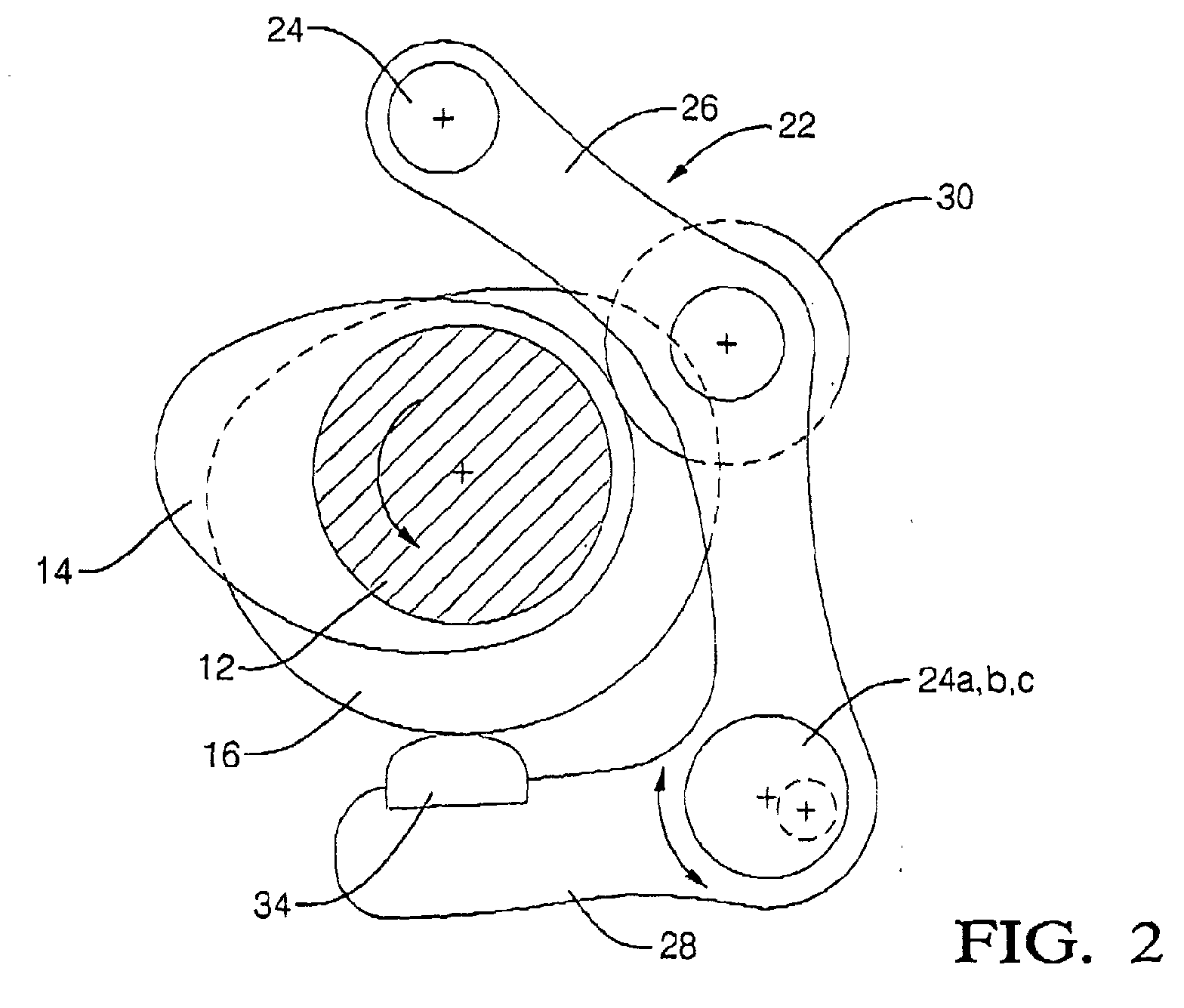
- FIG. 2 is an elevational view of a rocker assembly in accordance with the invention, showing an eccentric pivot pin for the rocker assembly; and
- FIGS. 3 through 5 are isometric views of three separate embodiments for eccentric pivot pins as shown in FIG. 2.
-
- Referring to FIG. 1, there is shown a portion of a
variable valve mechanism 10, including aninput camshaft 12 on which are mounted valve-opening cam lobe 14 and valve-closing cam lobe 16. The cam lobes are disposed in a predetermined angular relation relative to each other and relative to central axis A ofinput shaft 12. The pairedlobes 14,16 (only one pair shown) are spaced along the length ofinput shaft 12. Each respective pair ofcam lobes variable valve mechanism 10 and with a corresponding cylinder of an internal combustion engine (not shown). For purposes of clarity, a singlevariable valve mechanism 10 is discussed hereafter. - Opening
cam lobe 14 andclosing cam lobe 16 rotate as substantially one body withinput shaft 12. The lobes are, for example, affixed to or integral withshaft 12 which is received within and extends through rotary bearing mounts disposed on the head of the engine. -
Output cam 18 is oscillatably disposed onshaft 12 for actuation of a valve stem, tappet, or roller finger follower (none shown) in known fashion via contact witheccentric surface 20. Cam 18 is pivotably connected tolink 19 which is an elongate arm member pivotably coupled at a first end tooutput cam 18 and at a second and opposite end torocker assembly 22.Rocker assembly 22 is coupled, for example, bypins 24, to link 19 and to a frame member (omitted for clarity) about which it pivots upon axis B. The frame member may be independently rotated to various positions aboutshaft 12 to advance or retard the timing of valve opening, as disclosed in the incorporated reference patents.Rocker assembly 22 may be thought of as comprising twoarms First arm 26 carriesroller 30 which followingly engages valve-openingcam lobe 14 alongeccentric surface 32 and is pivotably pinned tolink 19 as discussed above. Asshaft 12 andlobe 14 rotate,roller 30 causesassembly 22 to pivot about axis B, thus causing, vialink 19,output cam 18 to oscillate aboutshaft 12. - Rocker
assembly 22 further includes a followingslider pad 34 disposed onsecond arm 28 which slidingly engages valve-closing cam lobe 16 alongeccentric surface 36.Lobes arms followers eccentric surfaces shaft 12. Thus the action ofrocker assembly 22 is fully controlled at all times and does not require use of return springs to assure proper motion. (In practice, the lash adjustment of the system optimally provides for a rest clearance of about 0.001" betweenslider 34 andsurface 36.) - As noted above, there is little room for error in the manufacture and installation of the components shown in FIG. 1, or of the receiving engine head and VVM mounting components as well.
Assembly 22 must haveroller 30 andslider 34 positioned accurately with respect to axis B such that they just touchsurfaces - Referring to FIG. 2,
rocker assembly 22 is substantially as configured in FIG. 1. However,pivot pin 24 is replaced with an improved pivot pin, shown as 24a,24b,24c in FIGS. 3-5 and as discussed below. The improved pivot pin has at least two cylindrical sections 38,40. The first cylindrical section 38 has anaxis 42 coaxial with the axis of the mounting frame (not shown) forrocker assembly 22. The second cylindrical section 40 has anaxis 44 coaxial with pivot axis B ofrocker assembly 22.Axes hexagonal socket 46 in the end of the pivot pin, the distance of axis B fromcam lobes axes 42 and 44). The eccentricity needed can be determined at the design stage after an analysis of the stack-up of manufacturing variances of the components of theVVM 10. - There are several variations in configuration of an improved pin having two offset cylindrical sections. The diameters of the sections can be of various sizes, depending upon the desired arrangement of components. For example, the designer may choose to have the smaller diameter in the supporting frame for the rocker assembly and the larger diameter in the rocker assembly, or vice versa.
- Referring to FIG. 3, an
improved pin 24a has two relatively large diameterfirst sections second section 40a.Pin 24a is useful where frames (not shown) on either side ofrocker assembly 22 have large diameter bores for receiving the relativelylarge diameter sections assembly 22 has a relatively small diameter bore for receivingsection 40a ofpin 24a. - Conversely, referring to FIG. 4, an
improved pin 24b has two relatively small diameterfirst sections second section 40b.Pin 24a is useful where frames (not shown) on either side ofrocker assembly 22 have small diameter bores for receiving the relativelysmall diameter sections assembly 22 has a large diameter bore for receivingsection 40b ofpin 24b. - Referring to FIG. 5, the desired eccentric adjustment may be obtained through use of either single or multiple cylindrical bushing(s) 48 disposed in either the frame bore or the rocker assembly bore.
Bushing 48 has an off-center bore 50 for receiving acylindrical pin 52 substantially equivalent toprior art pin 24, disposable in either the corresponding assembly bore or frame bore to form an equivalenteccentric pin 24c. As in use ofpins bushing 48 as by a hexagonal wrench, the mechanical lash in aVVM 10 may be adjusted. - It should be understood that in all embodiments in accordance with the invention, known means are to be employed for restricting further rotation of the eccentric pin after lash adjustment is complete, as by staking, set screws, clamps, and the like.
- While the invention has been described by reference to various specific embodiments, it should be understood that numerous changes may be made within the spirit and scope of the inventive concepts described. Accordingly, it is intended that the invention not be limited to the described embodiments, but will have full scope defined by the language of the following claims.
Claims (8)
- A pivot pin disposable in first and second bores in first and second elements, respectively, for pivoting of the second element relative to the first element about a pivot axis, said pin comprising first and second cylindrical elements having first and second axes, respectively, said first and second axes being parallel and offset from each other, such that rotation of said pivot pin in said first and second bores changes the location of said pivot axis with respect to said first element.
- A pivot pin in accordance with Claim 1 wherein said first element is a frame and said second element is a rocker assembly.
- A rocker assembly pivotable about a pivot axis for following a valve-opening cam lobe and a valve-closing cam lobe of a variable valve mechanism in an internal combustion engine, the mechanism having a frame for pivotably supporting the rocker assembly, comprising:a) a first arm;b) a first follower on said first arm for following said valve-opening cam lobe;c) a second arm disposed at an included angle from said first arm;d) a second follower on said second arm for following said valve-closing cam lobe; ande) a pivot pin disposable in said frame and disposed in said rocker assembly for pivoting of said rocker assembly about said pivot axis with respect to said frame, said pin having first and second cylindrical elements having first and second axes, respectively, said first and second axes being parallel and offset from each other, such that rotation of said pivot pin in said frame and said rocker assembly changes the distance between said pivot axis and said valve-opening and valve-closing cam lobes.
- A rocker assembly in accordance with Claim 3 wherein the diameter of said first cylindrical element is greater than the diameter of said second cylindrical element.
- A rocker assembly in accordance with Claim 3 wherein the diameter of said second cylindrical element is greater than the diameter of said first cylindrical element.
- A rocker assembly in accordance with Claim 3 wherein one of said first and second cylindrical elements is a cylindrical pin insertable through an off-center longitudinal bore in the other of said cylindrical elements.
- A variable valve mechanism for an internal combustion engine, comprising a rocker assembly pivotable about a pivot pin having a pivot axis for following a valve-opening cam lobe and a valve-closing cam lobe of the variable valve mechanism in an internal combustion engine, said mechanism having a frame for pivotably supporting said rocker assembly, said pivot pin being disposable in first and second bores in said frame and said rocker assembly, respectively, for pivoting of said rocker assembly relative to said frame about said pivot axis, said pin having first and second cylindrical elements having first and second axes, respectively, said first and second axes being parallel and offset from each other, such that rotation of said pivot pin in said first and second bores changes the location of said pivot axis with respect to said frame and to said cam lobes.
- An internal combustion engine comprising a variable valve mechanism including a rocker assembly pivotable about a pivot pin having a pivot axis for following a valve-opening cam lobe and a valve-closing cam lobe, said mechanism having a frame for pivotably supporting said rocker assembly, said pivot pin being disposed in first and second bores in said frame and said rocker assembly, respectively, for pivoting of said rocker assembly relative to said frame about said pivot axis, said pin having first and second cylindrical elements having first and second axes, respectively, said first and second axes being parallel and offset from each other, such that rotation of said pivot pin in said first and second bores changes the location of said pivot axis with respect to said frame and to said cam lobes.
Applications Claiming Priority (2)
| Application Number | Priority Date | Filing Date | Title |
|---|---|---|---|
| US875649 | 1978-02-06 | ||
| US09/875,649 US6439178B1 (en) | 2001-01-05 | 2001-06-06 | Mechanical lash adjuster apparatus for an engine cam |
Publications (2)
| Publication Number | Publication Date |
|---|---|
| EP1264967A2 true EP1264967A2 (en) | 2002-12-11 |
| EP1264967A3 EP1264967A3 (en) | 2003-10-15 |
Family
ID=25366137
Family Applications (1)
| Application Number | Title | Priority Date | Filing Date |
|---|---|---|---|
| EP02077184A Withdrawn EP1264967A3 (en) | 2001-06-06 | 2002-06-03 | Mechanical lash adjuster apparatus for an engine cam |
Country Status (2)
| Country | Link |
|---|---|
| US (1) | US6439178B1 (en) |
| EP (1) | EP1264967A3 (en) |
Cited By (1)
| Publication number | Priority date | Publication date | Assignee | Title |
|---|---|---|---|---|
| WO2009122196A1 (en) * | 2008-04-04 | 2009-10-08 | Mechadyne Plc | Engine valve system with variable lift and duration |
Families Citing this family (10)
| Publication number | Priority date | Publication date | Assignee | Title |
|---|---|---|---|---|
| US6736096B2 (en) * | 2002-02-21 | 2004-05-18 | Delphi Technologies, Inc. | Method and apparatus for setting valve lift within a cylinder |
| US6591802B1 (en) * | 2002-04-10 | 2003-07-15 | Delphi Technologies, Inc. | Variable valve actuating mechanism having a rotary hydraulic lash adjuster |
| US6532924B1 (en) * | 2002-04-10 | 2003-03-18 | Delphi Technologies, Inc. | Variable valve actuating mechanism having automatic lash adjustment means |
| US6722331B2 (en) * | 2002-06-28 | 2004-04-20 | Tecumseh Products Company | Valve clearance adjustment mechanism |
| US6584943B1 (en) * | 2002-09-18 | 2003-07-01 | Daimlerchrysler Corporation | Variable compound rocker system for push rod and overhead camshaft engines |
| CN100400804C (en) * | 2003-06-03 | 2008-07-09 | 本田技研工业株式会社 | engine valve train |
| JP4046078B2 (en) * | 2003-12-10 | 2008-02-13 | ソニー株式会社 | INPUT DEVICE, INPUT METHOD, AND ELECTRONIC DEVICE |
| JP4096938B2 (en) * | 2004-11-17 | 2008-06-04 | 日産自動車株式会社 | Lift adjustment device and lift adjustment method for valve operating mechanism |
| US7225776B2 (en) | 2004-11-17 | 2007-06-05 | General Motors Corporation | Valvetrain with two-step switchable rocker and deactivating stationary lash adjuster |
| WO2008023207A1 (en) * | 2006-08-22 | 2008-02-28 | Ricardo Deutschland Gmbh | Apparatus for adjusting the valve stroke in an internal combustion engine |
Citations (2)
| Publication number | Priority date | Publication date | Assignee | Title |
|---|---|---|---|---|
| US5937809A (en) | 1997-03-20 | 1999-08-17 | General Motors Corporation | Variable valve timing mechanisms |
| US6019076A (en) | 1998-08-05 | 2000-02-01 | General Motors Corporation | Variable valve timing mechanism |
Family Cites Families (11)
| Publication number | Priority date | Publication date | Assignee | Title |
|---|---|---|---|---|
| DE408310C (en) * | 1922-11-14 | 1925-01-10 | Steiner Carl | Valve control with angled rocker arm, especially for internal combustion engines |
| US2814283A (en) * | 1954-04-12 | 1957-11-26 | Daimler Benz Ag | Valve control mechanism, particularly for high speed internal combustion engines |
| US2833258A (en) * | 1955-04-28 | 1958-05-06 | Daimler Benz Ag | Valve mechanism for internal combustion engines |
| US3626469A (en) * | 1968-11-12 | 1971-12-07 | Gerald J Ashley | Valve gear |
| FR2519375B1 (en) * | 1981-12-31 | 1986-07-11 | Baguena Michel | VARIABLE VALVE FOR FOUR-STROKE ENGINE |
| DE68918317T2 (en) * | 1988-03-28 | 1995-01-19 | Nissan Motor | Control arrangement for poppet valves of an internal combustion engine and the like. |
| DE68905010T2 (en) * | 1988-08-16 | 1993-09-16 | Nissan Motor | ROCKER ARM ARRANGEMENT FOR PLATE VALVES OF AN INTERNAL COMBUSTION ENGINE. |
| US5048474A (en) * | 1989-02-22 | 1991-09-17 | Nissan Motor Co., Ltd. | Valve train for automotive engine |
| US5148783A (en) * | 1990-03-08 | 1992-09-22 | Suzuki Kabushiki Kaisha | Valve actuating mechanism in four-stroke cycle engine |
| US5025761A (en) * | 1990-06-13 | 1991-06-25 | Chen Kuang Tong | Variable valve-timing device |
| DE19859564B4 (en) * | 1997-12-26 | 2005-09-08 | Nissan Motor Co., Ltd., Yokohama | Variable valve adjuster |
-
2001
- 2001-06-06 US US09/875,649 patent/US6439178B1/en not_active Expired - Fee Related
-
2002
- 2002-06-03 EP EP02077184A patent/EP1264967A3/en not_active Withdrawn
Patent Citations (2)
| Publication number | Priority date | Publication date | Assignee | Title |
|---|---|---|---|---|
| US5937809A (en) | 1997-03-20 | 1999-08-17 | General Motors Corporation | Variable valve timing mechanisms |
| US6019076A (en) | 1998-08-05 | 2000-02-01 | General Motors Corporation | Variable valve timing mechanism |
Cited By (3)
| Publication number | Priority date | Publication date | Assignee | Title |
|---|---|---|---|---|
| WO2009122196A1 (en) * | 2008-04-04 | 2009-10-08 | Mechadyne Plc | Engine valve system with variable lift and duration |
| US8316807B2 (en) | 2008-04-04 | 2012-11-27 | Ian Methley | Engine valve system with variable lift and duration |
| CN101970809B (en) * | 2008-04-04 | 2013-02-13 | 米查戴尼股份有限公司 | Engine valve system with variable lift and duration |
Also Published As
| Publication number | Publication date |
|---|---|
| US20020088415A1 (en) | 2002-07-11 |
| EP1264967A3 (en) | 2003-10-15 |
| US6439178B1 (en) | 2002-08-27 |
Similar Documents
| Publication | Publication Date | Title |
|---|---|---|
| US6591798B2 (en) | Variable valve actuation assembly for an internal combustion engine | |
| EP1793098A2 (en) | System for variable valvetrain actuation | |
| US7314027B2 (en) | Variable valve unit for internal combustion engine | |
| US6439178B1 (en) | Mechanical lash adjuster apparatus for an engine cam | |
| US6422187B2 (en) | Variable valve mechanism having an eccentric-driven frame | |
| EP1911942A2 (en) | System for variable Valvetrain Actuation | |
| US5732669A (en) | Valve control for an internal combustion engine | |
| US6659053B1 (en) | Fully variable valve train | |
| US6422189B1 (en) | Mechanical lash control apparatus for an engine cam | |
| CA2418335A1 (en) | Internal combustion engine provided with decompressing means and method of adjusting valve lift for decompression | |
| US6868811B2 (en) | Frameless variable valve actuation mechanism | |
| US6491008B1 (en) | Variable valve timing adjustable roller rocker arm assembly | |
| JP4295171B2 (en) | Valve operating device for internal combustion engine | |
| GB2421765A (en) | Valve operating mechanism with two cams | |
| CN112539093A (en) | Valve timing and lift variable device for internal combustion engine and adjusting mode thereof | |
| US8919307B2 (en) | Valve train system for providing continuously variable valve lift | |
| US7546823B2 (en) | Variable overhead valve control for engines | |
| JP2004521245A (en) | Variable valve mechanism | |
| KR20060038471A (en) | Variable valve gear | |
| WO1998037315A1 (en) | Operating mechanisms for valves | |
| US20030172887A1 (en) | Offset varibale valve actuation mechanism | |
| JPH0622091Y2 (en) | Valve forced opening / closing device for internal combustion engine | |
| JP2003206714A (en) | Variable valve gear | |
| EP2211030B1 (en) | Variable Valve Mechanism | |
| JP2006233932A (en) | Method for adjusting valve opening / closing characteristics of rocker arm type valve gear |
Legal Events
| Date | Code | Title | Description |
|---|---|---|---|
| PUAI | Public reference made under article 153(3) epc to a published international application that has entered the european phase |
Free format text: ORIGINAL CODE: 0009012 |
|
| AK | Designated contracting states |
Kind code of ref document: A2 Designated state(s): AT BE CH CY DE DK ES FI FR GB GR IE IT LI LU MC NL PT SE TR |
|
| AX | Request for extension of the european patent |
Free format text: AL;LT;LV;MK;RO;SI |
|
| PUAL | Search report despatched |
Free format text: ORIGINAL CODE: 0009013 |
|
| AK | Designated contracting states |
Kind code of ref document: A3 Designated state(s): AT BE CH CY DE DK ES FI FR GB GR IE IT LI LU MC NL PT SE TR |
|
| AX | Request for extension of the european patent |
Extension state: AL LT LV MK RO SI |
|
| RIC1 | Information provided on ipc code assigned before grant |
Ipc: 7F 01L 1/20 B Ipc: 7F 01L 1/30 B Ipc: 7F 01L 13/00 B Ipc: 7F 01L 1/22 A |
|
| 17P | Request for examination filed |
Effective date: 20040415 |
|
| AKX | Designation fees paid |
Designated state(s): DE FR GB |
|
| 17Q | First examination report despatched |
Effective date: 20061207 |
|
| STAA | Information on the status of an ep patent application or granted ep patent |
Free format text: STATUS: THE APPLICATION IS DEEMED TO BE WITHDRAWN |
|
| 18D | Application deemed to be withdrawn |
Effective date: 20070418 |