EP1264791A1 - Sheet feeding and image forming apparatus and method - Google Patents
Sheet feeding and image forming apparatus and method Download PDFInfo
- Publication number
- EP1264791A1 EP1264791A1 EP02012347A EP02012347A EP1264791A1 EP 1264791 A1 EP1264791 A1 EP 1264791A1 EP 02012347 A EP02012347 A EP 02012347A EP 02012347 A EP02012347 A EP 02012347A EP 1264791 A1 EP1264791 A1 EP 1264791A1
- Authority
- EP
- European Patent Office
- Prior art keywords
- sheet
- rear side
- containing tray
- hitching
- sheet containing
- Prior art date
- Legal status (The legal status is an assumption and is not a legal conclusion. Google has not performed a legal analysis and makes no representation as to the accuracy of the status listed.)
- Granted
Links
- 238000000034 method Methods 0.000 title claims 2
- 238000005452 bending Methods 0.000 claims description 10
- 238000011144 upstream manufacturing Methods 0.000 claims description 5
- 230000000007 visual effect Effects 0.000 claims 3
- 230000008878 coupling Effects 0.000 description 2
- 238000010168 coupling process Methods 0.000 description 2
- 238000005859 coupling reaction Methods 0.000 description 2
- 238000000926 separation method Methods 0.000 description 2
- 241001236644 Lavinia Species 0.000 description 1
- 230000009194 climbing Effects 0.000 description 1
- 238000001514 detection method Methods 0.000 description 1
- 238000010586 diagram Methods 0.000 description 1
- 201000010099 disease Diseases 0.000 description 1
- 208000037265 diseases, disorders, signs and symptoms Diseases 0.000 description 1
- 230000005484 gravity Effects 0.000 description 1
- 230000004048 modification Effects 0.000 description 1
- 238000012986 modification Methods 0.000 description 1
- 238000011084 recovery Methods 0.000 description 1
Images



Classifications
-
- B—PERFORMING OPERATIONS; TRANSPORTING
- B65—CONVEYING; PACKING; STORING; HANDLING THIN OR FILAMENTARY MATERIAL
- B65H—HANDLING THIN OR FILAMENTARY MATERIAL, e.g. SHEETS, WEBS, CABLES
- B65H1/00—Supports or magazines for piles from which articles are to be separated
- B65H1/04—Supports or magazines for piles from which articles are to be separated adapted to support articles substantially horizontally, e.g. for separation from top of pile
-
- B—PERFORMING OPERATIONS; TRANSPORTING
- B65—CONVEYING; PACKING; STORING; HANDLING THIN OR FILAMENTARY MATERIAL
- B65H—HANDLING THIN OR FILAMENTARY MATERIAL, e.g. SHEETS, WEBS, CABLES
- B65H1/00—Supports or magazines for piles from which articles are to be separated
- B65H1/26—Supports or magazines for piles from which articles are to be separated with auxiliary supports to facilitate introduction or renewal of the pile
- B65H1/266—Support fully or partially removable from the handling machine, e.g. cassette, drawer
-
- B—PERFORMING OPERATIONS; TRANSPORTING
- B65—CONVEYING; PACKING; STORING; HANDLING THIN OR FILAMENTARY MATERIAL
- B65H—HANDLING THIN OR FILAMENTARY MATERIAL, e.g. SHEETS, WEBS, CABLES
- B65H3/00—Separating articles from piles
- B65H3/46—Supplementary devices or measures to assist separation or prevent double feed
- B65H3/56—Elements, e.g. scrapers, fingers, needles, brushes, acting on separated article or on edge of the pile
-
- B—PERFORMING OPERATIONS; TRANSPORTING
- B65—CONVEYING; PACKING; STORING; HANDLING THIN OR FILAMENTARY MATERIAL
- B65H—HANDLING THIN OR FILAMENTARY MATERIAL, e.g. SHEETS, WEBS, CABLES
- B65H2405/00—Parts for holding the handled material
- B65H2405/10—Cassettes, holders, bins, decks, trays, supports or magazines for sheets stacked substantially horizontally
- B65H2405/11—Parts and details thereof
- B65H2405/114—Side, i.e. portion parallel to the feeding / delivering direction
-
- B—PERFORMING OPERATIONS; TRANSPORTING
- B65—CONVEYING; PACKING; STORING; HANDLING THIN OR FILAMENTARY MATERIAL
- B65H—HANDLING THIN OR FILAMENTARY MATERIAL, e.g. SHEETS, WEBS, CABLES
- B65H2405/00—Parts for holding the handled material
- B65H2405/10—Cassettes, holders, bins, decks, trays, supports or magazines for sheets stacked substantially horizontally
- B65H2405/11—Parts and details thereof
- B65H2405/114—Side, i.e. portion parallel to the feeding / delivering direction
- B65H2405/1142—Projections or the like in surface contact with handled material
-
- B—PERFORMING OPERATIONS; TRANSPORTING
- B65—CONVEYING; PACKING; STORING; HANDLING THIN OR FILAMENTARY MATERIAL
- B65H—HANDLING THIN OR FILAMENTARY MATERIAL, e.g. SHEETS, WEBS, CABLES
- B65H2405/00—Parts for holding the handled material
- B65H2405/10—Cassettes, holders, bins, decks, trays, supports or magazines for sheets stacked substantially horizontally
- B65H2405/13—Elements acting on corner of sheet, e.g. snubber member
-
- B—PERFORMING OPERATIONS; TRANSPORTING
- B65—CONVEYING; PACKING; STORING; HANDLING THIN OR FILAMENTARY MATERIAL
- B65H—HANDLING THIN OR FILAMENTARY MATERIAL, e.g. SHEETS, WEBS, CABLES
- B65H2405/00—Parts for holding the handled material
- B65H2405/30—Other features of supports for sheets
- B65H2405/32—Supports for sheets partially insertable - extractable, e.g. upon sliding movement, drawer
-
- B—PERFORMING OPERATIONS; TRANSPORTING
- B65—CONVEYING; PACKING; STORING; HANDLING THIN OR FILAMENTARY MATERIAL
- B65H—HANDLING THIN OR FILAMENTARY MATERIAL, e.g. SHEETS, WEBS, CABLES
- B65H2601/00—Problem to be solved or advantage achieved
- B65H2601/10—Ensuring correct operation
- B65H2601/11—Clearing faulty handling, e.g. jams
Definitions
- the present invention generally relates to a sheet feeding apparatus for use in an image forming apparatus, such as a copier, a facsimile, a printer, etc., and more particularly to a sheet feeding apparatus including a sheet containing tray having a side guide member that aligns side ends of sheets set on the sheet containing tray and withdrawable from the image forming apparatus in a direction perpendicular to a sheet feeding direction.
- a so-called front loading type sheet feeding apparatus has been known in the past. Specifically, it includes a sheet containing tray withdrawable from a housed position to a front side of the apparatus body, a sheet feeding device for feeding sheets in a direction almost perpendicular to the withdrawal direction of the sheet containing tray, and a pair of side guide members extending in parallel to a sheet feeding direction for aligning side ends of the sheets.
- a pair of side fences 101 and 102 is arranged and aligns side ends of sheets (P) in a widthwise direction (B) perpendicular to the sheet feeding direction (A) on a sheet containing tray 100 of such a type of a sheet feeding apparatus.
- an end fence 103 so as to align a sheet-trailing end in an upstream side of the sheet feeding direction (A).
- the sheets (P) are raised by a bottom plate lifting apparatus (not shown) and then fed by the sheet feeding device such as a feeding roller when the uppermost sheet reaches a sheet feeding position located at a prescribed height for the sheet feeding device.
- the sheet feeding apparatus when the sheets are fed and sheet jam occurs on the sheet containing tray, a leading end of a jam sheet possibly remains in the vicinity of the feeding roller.
- the jam sheet P can unfortunately climb over a rear side fence 101.
- Japanese Patent Application Laid Open No. 9-77291 refers to a sheet remaining avoiding mechanism used for the similar purpose.
- a protruding section is upwardly formed from the rear side fence 101, and is setback from a rear side of a sheet setting range (i.e., a rear side end of a sheet).
- a sheet setting range i.e., a rear side end of a sheet.
- the sheet remaining avoiding mechanism of Japanese Patent Application Laid Open No. 9-175677 has a complex configuration. Specifically, sheet replenishment is disadvantageously difficult because a pair of sheet suppressing members largely horizontally protrudes from respective rear side and front side fences 101 and 102 toward a sheet stack range.
- an object of the present invention is to address and resolve the above-noted and other problems and provide a new sheet feeding apparatus.
- the above and other object are achieved according to the present invention by providing a novel sheet feeding apparatus including a sheet containing tray withdrawable from a housed position to a front side of an apparatus body.
- a sheet-feeding device is provided so as to feed a sheet on the sheet containing tray in a direction perpendicular to the withdrawal direction of the sheet containing tray.
- a pair of side aligning members is also provided so as to align widthwise ends of the sheets on the sheet containing tray.
- the aligning member of the rear side in the withdrawal direction includes a hitching member horizontally protruding toward a sheet setting range and hitch and prevent sheet from remaining when the sheet containing tray is withdrawn.
- the hitching member includes a protruding plate so as to overhang the uppermost sheet set on the sheet containing tray at a position a prescribed length downstream of a downstream end of the rear side-aligning member.
- a joining member is also provided so as to join the protruding plate and the rear side aligning member. The joining member positions a prescribed length behind a rear side end of the sheets aligned by the rear side-aligning member.
- the protruding plate slightly protrudes from the rear side end of the sheets.
- the protruding plate includes a slant and bending portion at its front side or rear side.
- a sheet containing tray attaching section may be formed in an apparatus body of the image forming apparatus 1 so as to attach a sheet containing tray 2 or the like.
- Three sheet containing trays 2 may be typically arranged and are enabled to slide back and forth on rails 14 as illustrated in Fig. 6.
- the sheet containing tray 2 may be withdrawable from the apparatus body 1 in a forward direction shown by an arrow (B) from a front side of the apparatus body 1 as illustrated in Fig. 2.
- the sheet containing tray 2 may include a pair of side fences 3 and 4 serving as side aligning members for aligning both side ends of a sheet P in a widthwise direction almost perpendicular to a sheet feeding direction shown by an arrow A. Also included may be an end fence 5 for aligning a trailing end of the sheet P directing the sheet feeding direction A. Such a sheet P may be set onto a bottom plate 6 as illustrated in Fig. 3.
- a bottom plate elevation apparatus may be provided and include an elevation arm 7 for lifting the bottom plate 6 and an elevation shaft 8 for rotating the elevation arm 7 below the bottom plate 6,.
- An elevation motor 9 may be provided in the apparatus body 1 and transmit rotational driving force to the elevation shaft 8.
- a setting detection device (not shown) may detect the tray, and then the elevation motor 9 may rotate.
- a coupling 10 may mesh and transmit the driving force to the elevation shaft 8.
- the elevation arm 7 may lift the bottom plate 6.
- the elevation motor 9 may stop driving, and thereby a sheet feeding available condition may be entered.
- the coupling 10 may disengage with the elevation shaft 8. As a result, the sheets P and bottom plate 6 may be lowered by gravity.
- the sheet-feeding device provided in the apparatus body 1 may be a publicly known friction separation type and mainly include a pickup roller 11, a feed roller 12, and a reverse roller 13. These pickup roller 11 and feed roller 12 may be engaged with an idler (not shown). The reverse roller 13 may always be oppositely rotated to a feeding direction so as to separate sheets P one by one.
- a hitching member 15 may be mounted on the rear side-fence 3 while directing in the direction B that sheet containing tray 2 is withdrawn so as to hitch and prevent a sheet from remaining in the apparatus body.
- the hitching member 15 may include a horizontally protruding plate 17 overhanging a sheet setting range, and a connecting member 16 for connecting the rear side-fence 3 and the horizontally protruding plate 17.
- the protruding plate 17 may overhang the uppermost sheet, and is disposed downstream of a downstream end of the rear side fence 3.
- a gap "r1" i.e., a space where the protruding plate is omitted
- a connecting member 16 may maintain the gap "r1” and is set back from the sheet setting range of the sheets stacked in front of the rear side fence 3.
- another gap "r2" may be formed as illustrated in Fig. 5B.
- the horizontally protruding plate 17 of Fig. 3A may be maintained at a prescribed height "h" not to contact the uppermost sheet P when the bottom plate is lifted.
- Driving may be immediately stopped in order to prevent progression of the disease of a jam condition when jam occurs in the apparatus body.
- jam treatment is performed while opening a vertical sheet conveyance path as illustrated by a dotted line in Fig. 1.
- a jam sheet P' whose leading end is stopped in the vicinity of the feed roller 12 can not be treated because a jam portion is too far from the opening section to reach, and then the sheet containing tray 2 is withdrawn to the front side by an operator.
- the jam sheet P' necessarily collides the rear side fence 3 and thereby sometimes is largely bent by the rear side fence 3 as illustrated in Fig. 4 when the sheet containing tray is withdrawn in the direction (B) as mentioned earlier.
- the hitching member 15 positions at a middle portion of the rear side fence 3 in the sheet feeding direction and upwardly extends there, the jam sheet P' highly probably climbs over the rear side fence 3 and the hitching member 15 from its largely bending portion.
- the hitching member 15 since the hitching member 15 is located downstream of the downstream side end of the rear side fence 3 as in the present invention, the jam sheet P' may not collide or sometimes slightly collides the rear side fence 3. Specifically, the jam sheet having less bending amount at its downstream side end than the other portion of the sheet may enter into the gaps "r1" and "r2" in this order, and is then hitched by the hitching member 15.
- the hitching member 15 is located downstream of the downstream end of the rear side fence 3, a jam sheet having a small size may be prevented from remaining, which is generally caused because its trailing end tends to sneak a gap formed between the right side wall 2' and rear side fence 3.
- the jam sheet P' may more easily enter into both the gaps "r1" and “r2". Specifically, it may credibly be hitched and withdrawn together with the sheet containing tray 2. The slight amount of "d” may not spoil a sheet setting performance in view of sheet bending when the sheet stack is set from the above. Since the hitching member 15 protrudes toward the sheet setting range by the slight amount of "d", a sheet can be damaged depending upon a setting manner in the above described embodiment. Then, as illustrated in Fig.
- the leading section (i.e., a front side end) of the protruding plate 17 includes a slant and bending portion 17a
- the slant and bending portion 17a may guide a sheet stack when it is loaded and prevent the same from being damaged.
- the other leading section (i.e., a rear side end) of the protruding plate 17 also includes a slant and bending portion 17b, these slant and bending portions 17a and 17b may guide a sheet stack to the housed position while preventing the sheet containing tray 2 from collision to either the apparatus body or a upper sheet containing tray. In addition, sheet damage may also be prevented.
- a friction pad type sheet feeding apparatus can be employed for the friction separation roller type sheet-feeding apparatus described earlier.
- the above-described hitching section integral with the rear side fence can be separated therefrom.
- the above-described sheet feeding apparatus integral with the image forming apparatus can be separated therefrom and employ the present invention.
- a second hitching section 218 can be provided in addition to and in an upstream position of the hitching section 218 on the rear side fence 3.
- the second hitching section may also include a horizontally protruding plate 220 at a rear side of the sheet setting range on the sheet containing tray 2, a connecting portion 219 for connecting the protruding plate 220 to the side fence 203, and an eave 221 projecting downstream from the protruding plate 220.
- a height of the side fence 203 may be lowered at a portion attaching the hitching section 218 than the remaining portion of the side fence 203.
- a gap "r3" may be formed between the protruding plate 220 and side fence 203.
- the gap "r3" can be large enough to hitch a jam sheet.
- the second hitching section 218 may also be set back from the sheet setting range, the sheet stack may not collide the hitching section 218 and avoid damage therefrom when set on the sheet containing tray.
- the second hitching section 218 may preferably be positioned substantially at the center of a side of the smallest sheet among various sizes of sheets. In such a situation, it surely hitches the jam sheet P' having the smaller size.
- the hitching member is preferably arranged above the rear side member, preferably at least with respect to a part of the rear side member. Preferably, there is a gap between the hitching member and the rear side member. Preferably, the gap is wider than the thickness of a sheet such that a sheet may enter the gap. Preferably, the hitching member is formed such that a sheet is gripped or hitched by the hitching member, in particular, when the sheet enters via afore-mentioned gap. Preferably, the hitching member projects from the aligning member in order to block a movement of a sheet beyond the rear side aligning member such that the sheet may not pass the rear side aligning member.
- the hitching member is arranged above the top sheet of a sheet stack arranged in the sheet containing tray.
- a hitching member is arranged at a height with respect to the bottom of the sheet containing tray which is higher than the height of the outlet for the sheet to be set.
- the hitching member has a hook like shape in order to hook sheets which tend to pass the rear side aligning member.
- the hitching member is arranged and constituted such that a movement of the sheet towards the rear side of the sheet containing tray is hindered or blocked if the sheet is above the afore-mentioned sheet outlet.
- the hitching member is arranged downstream of the upstream end of the rear side aligning member, preferably, around or more preferably downstream of a mid portion of the rear side aligning member such that a mid portion or more preferably a downstream portion of a sheet is prevented to pass the rear side aligning member.
- a sheet feeding apparatus includes a sheet containing tray withdrawable from a housed position to a front side of an apparatus body.
- a sheet-feeding device is provided so as to feed sheets on the sheet containing tray in a direction perpendicular to a withdrawal direction of the sheet containing tray.
- a pair of side aligning members is also provided so as to align widthwise ends of the sheets.
- a rear side aligning member mounts a hitching member so as to hitch and prevent a jam sheet from remaining in an apparatus body when the sheet containing tray is withdrawn.
- the hitching member includes a horizontally protruding plate so as to overhang the uppermost sheet set on the sheet containing tray at a position a prescribed length downstream of a downstream end of the rear side-aligning member.
- a joining portion is also provided so as to join the projection plate and the rear side-aligning member. The joining portion positions a prescribed length behind a rear side end of the sheets.
Landscapes
- Engineering & Computer Science (AREA)
- Mechanical Engineering (AREA)
- Sheets, Magazines, And Separation Thereof (AREA)
Abstract
Description
- This application claims priority under 35 USC §119 to Japanese Patent Application No. 13-172860 filed on June 07, 2001, the entire contents of which are herein incorporated by reference.
- The present invention generally relates to a sheet feeding apparatus for use in an image forming apparatus, such as a copier, a facsimile, a printer, etc., and more particularly to a sheet feeding apparatus including a sheet containing tray having a side guide member that aligns side ends of sheets set on the sheet containing tray and withdrawable from the image forming apparatus in a direction perpendicular to a sheet feeding direction.
- A so-called front loading type sheet feeding apparatus has been known in the past. Specifically, it includes a sheet containing tray withdrawable from a housed position to a front side of the apparatus body, a sheet feeding device for feeding sheets in a direction almost perpendicular to the withdrawal direction of the sheet containing tray, and a pair of side guide members extending in parallel to a sheet feeding direction for aligning side ends of the sheets. As illustrated in Fig. 7, a pair of
side fences sheet containing tray 100 of such a type of a sheet feeding apparatus. Also provided is anend fence 103 so as to align a sheet-trailing end in an upstream side of the sheet feeding direction (A). - The sheets (P) are raised by a bottom plate lifting apparatus (not shown) and then fed by the sheet feeding device such as a feeding roller when the uppermost sheet reaches a sheet feeding position located at a prescribed height for the sheet feeding device. In the sheet feeding apparatus, when the sheets are fed and sheet jam occurs on the sheet containing tray, a leading end of a jam sheet possibly remains in the vicinity of the feeding roller. Thus, when a user draws the
sheet containing tray 100 in the direction (B) in order to remove the jam sheet P, the jam sheet P can unfortunately climb over arear side fence 101. In particular, when a small size sheet is utilized, a problem sometimes arises such that the small size sheet sneaks through a gap (s) formed between a right side wall 100' of the sheet containing tray and therear side fence 101, and remains in the apparatus body as illustrated by a dotted line in Fig. 7. When the jam sheet P' having climbed over theside fence 101 remains in the apparatus body, it is difficult for a user to remove the same, and "call jam" requiring a request to a service person arises. Accordingly, a prompt jam recovery operation is disadvantageously not achieved. As a result, a working ratio is lowered. - Japanese Patent Application Laid Open No. 9-77291 refers to a sheet remaining avoiding mechanism used for the similar purpose. Specifically, a protruding section is upwardly formed from the
rear side fence 101, and is setback from a rear side of a sheet setting range (i.e., a rear side end of a sheet). Thus, when the sheet containing tray is withdrawn, the jam sheet P' collides the rear side-fence 101 and is largely bent. However, it is not blocked by the protruding section and climbs over the side fence and protruding section. If the protruding section hangs over at a position certainly higher than a side fence upper surface, a jam sheet climbing over can surely be blocked. However, due to multi-step tendency in sheet containing trays of an image forming apparatus of recent date, a height per a step is suppressed, and as a result, that of the vertically protruding section can not sufficiently be assigned. - Further, the sheet remaining avoiding mechanism of Japanese Patent Application Laid Open No. 9-175677 has a complex configuration. Specifically, sheet replenishment is disadvantageously difficult because a pair of sheet suppressing members largely horizontally protrudes from respective rear side and
front side fences - Accordingly, an object of the present invention is to address and resolve the above-noted and other problems and provide a new sheet feeding apparatus. The above and other object are achieved according to the present invention by providing a novel sheet feeding apparatus including a sheet containing tray withdrawable from a housed position to a front side of an apparatus body. A sheet-feeding device is provided so as to feed a sheet on the sheet containing tray in a direction perpendicular to the withdrawal direction of the sheet containing tray. A pair of side aligning members is also provided so as to align widthwise ends of the sheets on the sheet containing tray. The aligning member of the rear side in the withdrawal direction includes a hitching member horizontally protruding toward a sheet setting range and hitch and prevent sheet from remaining when the sheet containing tray is withdrawn. The hitching member includes a protruding plate so as to overhang the uppermost sheet set on the sheet containing tray at a position a prescribed length downstream of a downstream end of the rear side-aligning member. A joining member is also provided so as to join the protruding plate and the rear side aligning member. The joining member positions a prescribed length behind a rear side end of the sheets aligned by the rear side-aligning member.
- In another embodiment, the protruding plate slightly protrudes from the rear side end of the sheets.
- In yet another embodiment, the protruding plate includes a slant and bending portion at its front side or rear side.
- A more complete appreciation of the present invention and many of the attendant advantages thereof will be readily obtained as the same becomes better understood by reference to the following detailed description when considered in connection with the accompanying drawings, wherein:
- Fig. 1 is a schematic diagram illustrating an image forming apparatus employing sheet feeding apparatus according to the present invention;
- Fig. 2 is a plan view for illustrating the sheet feeding apparatus according to the present invention;
- Figs. 3A and 3B are enlarged explanatory charts illustrating a main section and a cross sectional view along the I-I line of Fig. 2;
- Fig. 4 is a cross sectional view along the II-II line of Fig. 2 for illustrating a bending condition of a sheet on a sheet containing tray;
- Figs. 5A and 5B are enlarged explanatory charts for illustrating a main section and a cross sectional view along the III-III line of Fig. 2;
- Fig. 6 is a perspective view for illustrating a sheet containing tray in the sheet feeding apparatus;
- Fig. 7 is perspective view for illustrating a conventional- sheet feeding apparatus;
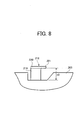
- Fig. 8 is a schematic chart for illustrating a second hitching member according to the present invention; and
- Fig. 9 is a chart for illustrating a condition when a jam sheet climbs over a first-hitching member in the sheet feeding apparatus.
-
- Referring now to the drawings, wherein like reference numerals designate identical or corresponding parts throughout the several views, and in particular to Fig. 1, a schematic front view of an image forming apparatus having an exemplary sheet feeding apparatus is illustrated. In the drawing, a sheet containing tray attaching section may be formed in an apparatus body of the
image forming apparatus 1 so as to attach asheet containing tray 2 or the like. Threesheet containing trays 2 may be typically arranged and are enabled to slide back and forth onrails 14 as illustrated in Fig. 6. Thus thesheet containing tray 2 may be withdrawable from theapparatus body 1 in a forward direction shown by an arrow (B) from a front side of theapparatus body 1 as illustrated in Fig. 2. - One of
sheet containing trays 2 is now described with reference to Figs. 3 to 5 illustrating cross sectional views along I-I, II-II, III-III lines of Fig. 2, respectively. In Figs. 2 to 4, thesheet containing tray 2 may include a pair ofside fences end fence 5 for aligning a trailing end of the sheet P directing the sheet feeding direction A. Such a sheet P may be set onto abottom plate 6 as illustrated in Fig. 3. A bottom plate elevation apparatus may be provided and include anelevation arm 7 for lifting thebottom plate 6 and anelevation shaft 8 for rotating theelevation arm 7 below thebottom plate 6,. Anelevation motor 9 may be provided in theapparatus body 1 and transmit rotational driving force to theelevation shaft 8. When thesheet containing tray 2 is set to theapparatus body 1, a setting detection device (not shown) may detect the tray, and then theelevation motor 9 may rotate. Acoupling 10 may mesh and transmit the driving force to theelevation shaft 8. Thus, theelevation arm 7 may lift thebottom plate 6. When the uppermost sheet P reaches a prescribed sheet feeding position, theelevation motor 9 may stop driving, and thereby a sheet feeding available condition may be entered. In contrast, when thesheet containing tray 2 is withdrawn from theapparatus body 1, thecoupling 10 may disengage with theelevation shaft 8. As a result, the sheets P andbottom plate 6 may be lowered by gravity. - The sheet-feeding device provided in the
apparatus body 1 may be a publicly known friction separation type and mainly include apickup roller 11, afeed roller 12, and areverse roller 13. Thesepickup roller 11 andfeed roller 12 may be engaged with an idler (not shown). Thereverse roller 13 may always be oppositely rotated to a feeding direction so as to separate sheets P one by one. Among theside fences member 15 may be mounted on the rear side-fence 3 while directing in the direction B thatsheet containing tray 2 is withdrawn so as to hitch and prevent a sheet from remaining in the apparatus body. The hitchingmember 15 may include a horizontally protrudingplate 17 overhanging a sheet setting range, and a connectingmember 16 for connecting the rear side-fence 3 and the horizontally protrudingplate 17. - In a first embodiment of the present invention, as illustrated in Figs. 3A and 3B, the protruding
plate 17 may overhang the uppermost sheet, and is disposed downstream of a downstream end of therear side fence 3. Thus, a gap "r1" (i.e., a space where the protruding plate is omitted) may be formed between the protrudingplate 17 and the down streamside of therear side fence 3. Further, a connectingmember 16 may maintain the gap "r1" and is set back from the sheet setting range of the sheets stacked in front of therear side fence 3. Thus, another gap "r2" may be formed as illustrated in Fig. 5B. Further, the horizontally protrudingplate 17 of Fig. 3A may be maintained at a prescribed height "h" not to contact the uppermost sheet P when the bottom plate is lifted. - Driving may be immediately stopped in order to prevent progression of the disease of a jam condition when jam occurs in the apparatus body. In such a case, jam treatment is performed while opening a vertical sheet conveyance path as illustrated by a dotted line in Fig. 1. However, a jam sheet P' whose leading end is stopped in the vicinity of the
feed roller 12 can not be treated because a jam portion is too far from the opening section to reach, and then thesheet containing tray 2 is withdrawn to the front side by an operator. The jam sheet P' necessarily collides therear side fence 3 and thereby sometimes is largely bent by therear side fence 3 as illustrated in Fig. 4 when the sheet containing tray is withdrawn in the direction (B) as mentioned earlier. In this situation, if the hitchingmember 15 positions at a middle portion of therear side fence 3 in the sheet feeding direction and upwardly extends there, the jam sheet P' highly probably climbs over therear side fence 3 and the hitchingmember 15 from its largely bending portion. In contrast, since the hitchingmember 15 is located downstream of the downstream side end of therear side fence 3 as in the present invention, the jam sheet P' may not collide or sometimes slightly collides therear side fence 3. Specifically, the jam sheet having less bending amount at its downstream side end than the other portion of the sheet may enter into the gaps "r1" and "r2" in this order, and is then hitched by the hitchingmember 15. - Further, since the hitching
member 15 is located downstream of the downstream end of therear side fence 3, a jam sheet having a small size may be prevented from remaining, which is generally caused because its trailing end tends to sneak a gap formed between the right side wall 2' andrear side fence 3. - As illustrated in Fig. 5A, since a front side end of the protruding
plate 17 horizontally protrudes toward the sheet setting range by a slight amount of "d", the jam sheet P' may more easily enter into both the gaps "r1" and "r2". Specifically, it may credibly be hitched and withdrawn together with thesheet containing tray 2. The slight amount of "d" may not spoil a sheet setting performance in view of sheet bending when the sheet stack is set from the above. Since the hitchingmember 15 protrudes toward the sheet setting range by the slight amount of "d", a sheet can be damaged depending upon a setting manner in the above described embodiment. Then, as illustrated in Fig. 5B, since the leading section (i.e., a front side end) of the protrudingplate 17 includes a slant and bendingportion 17a, the slant and bendingportion 17a may guide a sheet stack when it is loaded and prevent the same from being damaged. - In addition, since the other leading section (i.e., a rear side end) of the protruding
plate 17 also includes a slant and bendingportion 17b, these slant and bendingportions sheet containing tray 2 from collision to either the apparatus body or a upper sheet containing tray. In addition, sheet damage may also be prevented. - For the friction separation roller type sheet-feeding apparatus described earlier, a friction pad type sheet feeding apparatus can be employed. The above-described hitching section integral with the rear side fence can be separated therefrom. Further, the above-described sheet feeding apparatus integral with the image forming apparatus can be separated therefrom and employ the present invention.
- Further, as illustrated in Figs. 8 and 9, a second hitching
section 218 can be provided in addition to and in an upstream position of the hitchingsection 218 on therear side fence 3. The second hitching section may also include a horizontally protrudingplate 220 at a rear side of the sheet setting range on thesheet containing tray 2, a connectingportion 219 for connecting the protrudingplate 220 to theside fence 203, and aneave 221 projecting downstream from the protrudingplate 220. - A height of the
side fence 203 may be lowered at a portion attaching the hitchingsection 218 than the remaining portion of theside fence 203. Thus, a gap "r3" may be formed between the protrudingplate 220 andside fence 203. - Thus, even when the jam sheet P' rarely climbs over the hitching
member 15, an upstream portion of the jam sheet P' can possibly be hitched by the second hitchingsection 218 and enter into the gap "r3". Thus, the jam sheet P' can be withdrawn together with thesheet containing tray 202. - Since the
side fence 203 is lowered at the hitchingsection 218 attaching portion, the gap "r3" can be large enough to hitch a jam sheet. In addition, the second hitchingsection 218 may also be set back from the sheet setting range, the sheet stack may not collide the hitchingsection 218 and avoid damage therefrom when set on the sheet containing tray. Further, the second hitchingsection 218 may preferably be positioned substantially at the center of a side of the smallest sheet among various sizes of sheets. In such a situation, it surely hitches the jam sheet P' having the smaller size. - Obviously, numerous additional modifications and variations of the present invention are possible in light of e above teachings. It is therefore to be understood that within the scope of the appended claims, the present invention may be practiced otherwise than as specifically described herein.
- The hitching member is preferably arranged above the rear side member, preferably at least with respect to a part of the rear side member. Preferably, there is a gap between the hitching member and the rear side member. Preferably, the gap is wider than the thickness of a sheet such that a sheet may enter the gap. Preferably, the hitching member is formed such that a sheet is gripped or hitched by the hitching member, in particular, when the sheet enters via afore-mentioned gap. Preferably, the hitching member projects from the aligning member in order to block a movement of a sheet beyond the rear side aligning member such that the sheet may not pass the rear side aligning member. Preferably, the hitching member is arranged above the top sheet of a sheet stack arranged in the sheet containing tray. Preferably, a hitching member is arranged at a height with respect to the bottom of the sheet containing tray which is higher than the height of the outlet for the sheet to be set. Preferably, the hitching member has a hook like shape in order to hook sheets which tend to pass the rear side aligning member. Preferably, the hitching member is arranged and constituted such that a movement of the sheet towards the rear side of the sheet containing tray is hindered or blocked if the sheet is above the afore-mentioned sheet outlet. Preferably, the hitching member is arranged downstream of the upstream end of the rear side aligning member, preferably, around or more preferably downstream of a mid portion of the rear side aligning member such that a mid portion or more preferably a downstream portion of a sheet is prevented to pass the rear side aligning member.
- A sheet feeding apparatus includes a sheet containing tray withdrawable from a housed position to a front side of an apparatus body. A sheet-feeding device is provided so as to feed sheets on the sheet containing tray in a direction perpendicular to a withdrawal direction of the sheet containing tray. A pair of side aligning members is also provided so as to align widthwise ends of the sheets. A rear side aligning member mounts a hitching member so as to hitch and prevent a jam sheet from remaining in an apparatus body when the sheet containing tray is withdrawn. The hitching member includes a horizontally protruding plate so as to overhang the uppermost sheet set on the sheet containing tray at a position a prescribed length downstream of a downstream end of the rear side-aligning member. A joining portion is also provided so as to join the projection plate and the rear side-aligning member. The joining portion positions a prescribed length behind a rear side end of the sheets.
Claims (9)
- A sheet feeding apparatus, comprising:a sheet containing tray withdrawable from a housed position to a front side of an apparatus body;a sheet feeding device configured to feed a sheet on the sheet containing tray in a direction perpendicular to a withdrawal direction of the sheet containing tray;a pair of side aligning members configured to align widthwise ends of the sheets set within a sheet setting range on the sheet containing tray; anda hitching member mounted on the sheet containing tray behind a rear side of the sheets, wherein said hitching member is positioned on the sheet containing tray a prescribed length downstream of a downstream end of the rear side aligning member and/or wherein said hitching member is at least partly arranged above and/or downstream of an upstream end of the rear side aligning member and/or constituted such that it hinders a sheet about to be fed passing the rear side aligning member.
- The sheet feeding apparatus according to claim 1, wherein said hitching member is secured to the rear side aligning member.
- The sheet feeding apparatus according to any one of claims 1 and 2, wherein said hitching member includes a horizontally protruding plate configured to protrude toward the sheet setting range and overhang the uppermost sheet set on the sheet containing tray.
- The sheet feeding apparatus according to claim 3, wherein said hitching member includes a joining member configured to join the protruding plate and the rear side aligning member, said joining member positioning a prescribed length behind a rear side end of the sheet aligned by the rear side-aligning member.
- The sheet feeding apparatus, according to claim 4, wherein said protruding plate forwardly slightly protrudes from the rear side end of the sheets so that sheet replenishment from above is substantially not interfered by the protruding plate.
- The sheet feeding apparatus, according to claim 4, wherein said protruding plate includes a slant portion configured to guide the sheets to be replenished at its front side end when sheets are replenished from the above.
- The sheet feeding apparatus, according to claim 3, wherein said protruding plate includes a slant portion configured to form a guiding portion at its rear side end when the sheet feeding apparatus is housed.
- An image forming apparatus including:a visual image forming and transferring device configured to forming and transferring a visual image onto a sheet; anda sheet feeding device configured as claimed in any one of claims 1 to 7 for feeding a sheet to receive the visual image.
- A method for hitching a jam sheet jamming on a sheet containing tray, comprising the steps of:providing a pair of side aligning members configured to align widthwise ends of the sheets set on the sheet containing tray;providing a hitching member on the sheet containing tray behind a rear side of the sheets and downstream of a downstream end of the rear side aligning member; andwithdrawing a sheet containing tray from a housed position to a front side of an apparatus body when a jam occurs;hitching a relatively smaller bending portion of the jam sheet jamming in the vicinity of an outlet of the sheet containing tray with the hitching member when said step of withdrawing a sheet feeding tray is performed.
Applications Claiming Priority (2)
| Application Number | Priority Date | Filing Date | Title |
|---|---|---|---|
| JP2001172860 | 2001-06-07 | ||
| JP2001172860 | 2001-06-07 |
Publications (2)
| Publication Number | Publication Date |
|---|---|
| EP1264791A1 true EP1264791A1 (en) | 2002-12-11 |
| EP1264791B1 EP1264791B1 (en) | 2006-04-26 |
Family
ID=19014420
Family Applications (1)
| Application Number | Title | Priority Date | Filing Date |
|---|---|---|---|
| EP02012347A Expired - Lifetime EP1264791B1 (en) | 2001-06-07 | 2002-06-05 | Sheet feeding and image forming apparatus and method |
Country Status (2)
| Country | Link |
|---|---|
| EP (1) | EP1264791B1 (en) |
| DE (1) | DE60210863T2 (en) |
Cited By (1)
| Publication number | Priority date | Publication date | Assignee | Title |
|---|---|---|---|---|
| US7600749B2 (en) | 2004-12-20 | 2009-10-13 | Samsung Electronics Co., Ltd. | Paper feeding device and image forming apparatus including the same |
Citations (2)
| Publication number | Priority date | Publication date | Assignee | Title |
|---|---|---|---|---|
| JPH0977291A (en) * | 1995-09-14 | 1997-03-25 | Ricoh Co Ltd | Paper feeder |
| JPH09175677A (en) * | 1995-12-26 | 1997-07-08 | Ricoh Co Ltd | Paper feeder |
-
2002
- 2002-06-05 EP EP02012347A patent/EP1264791B1/en not_active Expired - Lifetime
- 2002-06-05 DE DE60210863T patent/DE60210863T2/en not_active Expired - Lifetime
Patent Citations (2)
| Publication number | Priority date | Publication date | Assignee | Title |
|---|---|---|---|---|
| JPH0977291A (en) * | 1995-09-14 | 1997-03-25 | Ricoh Co Ltd | Paper feeder |
| JPH09175677A (en) * | 1995-12-26 | 1997-07-08 | Ricoh Co Ltd | Paper feeder |
Non-Patent Citations (2)
| Title |
|---|
| PATENT ABSTRACTS OF JAPAN vol. 1997, no. 07 31 July 1997 (1997-07-31) * |
| PATENT ABSTRACTS OF JAPAN vol. 1997, no. 11 28 November 1997 (1997-11-28) * |
Cited By (1)
| Publication number | Priority date | Publication date | Assignee | Title |
|---|---|---|---|---|
| US7600749B2 (en) | 2004-12-20 | 2009-10-13 | Samsung Electronics Co., Ltd. | Paper feeding device and image forming apparatus including the same |
Also Published As
| Publication number | Publication date |
|---|---|
| DE60210863D1 (en) | 2006-06-01 |
| EP1264791B1 (en) | 2006-04-26 |
| DE60210863T2 (en) | 2007-05-24 |
Similar Documents
| Publication | Publication Date | Title |
|---|---|---|
| JP3335973B2 (en) | Paper feeder | |
| US8070150B2 (en) | Sheet ejection device, image forming apparatus and sheet finisher provided therewith | |
| US7753358B2 (en) | Tabbed sheet support unit, sheet feeding device, and image forming apparatus | |
| US6651976B2 (en) | Sheet feeding and image forming apparatus and method | |
| EP1264791B1 (en) | Sheet feeding and image forming apparatus and method | |
| EP2246196A3 (en) | Image forming apparatus | |
| US6902161B2 (en) | Sheet feeder avoiding sheet sag | |
| US7490824B2 (en) | Image forming apparatus | |
| US20040251601A1 (en) | Sheet feeder device, image reading apparatus and image forming apparatus | |
| JP4766687B2 (en) | Sheet stacking apparatus and image forming system having the same | |
| JP2002255359A (en) | Sheet position regulating stacking device and image recording device equipped with the device | |
| EP0864435A1 (en) | Overfill control apparatus for a media input tray | |
| JP3481743B2 (en) | Paper feeder | |
| KR100449024B1 (en) | paper-feeding apparatus having a part for varying the paper-entering angle in an office machine | |
| CN102485621B (en) | Paper stopping mechanism of automatic paper feeding device | |
| JP3973969B2 (en) | Paper feeding device and image forming apparatus | |
| JP7159724B2 (en) | Media feeding device and image forming device | |
| CN1797225B (en) | Image forming apparatus, paper sheet transporting device, and paper sheet feeding device | |
| JP3277962B2 (en) | Paper feeder | |
| CA2015600A1 (en) | Dual mode document feeder | |
| US20250033917A1 (en) | Sheet feeding device and image forming apparatus | |
| JP2003192159A (en) | Paper feeder | |
| JP2002347956A (en) | Paper feeder and image forming apparatus | |
| EP4596471A1 (en) | Sheet alignment device | |
| US7021886B2 (en) | Paper supply system and cart for a high-speed sheet feeder |
Legal Events
| Date | Code | Title | Description |
|---|---|---|---|
| PUAI | Public reference made under article 153(3) epc to a published international application that has entered the european phase |
Free format text: ORIGINAL CODE: 0009012 |
|
| AK | Designated contracting states |
Kind code of ref document: A1 Designated state(s): AT BE CH CY DE DK ES FI FR GB GR IE IT LI LU MC NL PT SE TR |
|
| AX | Request for extension of the european patent |
Free format text: AL;LT;LV;MK;RO;SI |
|
| 17P | Request for examination filed |
Effective date: 20030131 |
|
| AKX | Designation fees paid |
Designated state(s): DE FR GB |
|
| 17Q | First examination report despatched |
Effective date: 20031223 |
|
| GRAP | Despatch of communication of intention to grant a patent |
Free format text: ORIGINAL CODE: EPIDOSNIGR1 |
|
| GRAS | Grant fee paid |
Free format text: ORIGINAL CODE: EPIDOSNIGR3 |
|
| GRAA | (expected) grant |
Free format text: ORIGINAL CODE: 0009210 |
|
| AK | Designated contracting states |
Kind code of ref document: B1 Designated state(s): DE FR GB |
|
| REG | Reference to a national code |
Ref country code: GB Ref legal event code: FG4D |
|
| REF | Corresponds to: |
Ref document number: 60210863 Country of ref document: DE Date of ref document: 20060601 Kind code of ref document: P |
|
| ET | Fr: translation filed | ||
| PLBE | No opposition filed within time limit |
Free format text: ORIGINAL CODE: 0009261 |
|
| STAA | Information on the status of an ep patent application or granted ep patent |
Free format text: STATUS: NO OPPOSITION FILED WITHIN TIME LIMIT |
|
| 26N | No opposition filed |
Effective date: 20070129 |
|
| REG | Reference to a national code |
Ref country code: FR Ref legal event code: PLFP Year of fee payment: 15 |
|
| REG | Reference to a national code |
Ref country code: FR Ref legal event code: PLFP Year of fee payment: 16 |
|
| PGFP | Annual fee paid to national office [announced via postgrant information from national office to epo] |
Ref country code: GB Payment date: 20170620 Year of fee payment: 16 Ref country code: DE Payment date: 20170621 Year of fee payment: 16 Ref country code: FR Payment date: 20170621 Year of fee payment: 16 |
|
| REG | Reference to a national code |
Ref country code: DE Ref legal event code: R119 Ref document number: 60210863 Country of ref document: DE |
|
| GBPC | Gb: european patent ceased through non-payment of renewal fee |
Effective date: 20180605 |
|
| PG25 | Lapsed in a contracting state [announced via postgrant information from national office to epo] |
Ref country code: FR Free format text: LAPSE BECAUSE OF NON-PAYMENT OF DUE FEES Effective date: 20180630 Ref country code: GB Free format text: LAPSE BECAUSE OF NON-PAYMENT OF DUE FEES Effective date: 20180605 Ref country code: DE Free format text: LAPSE BECAUSE OF NON-PAYMENT OF DUE FEES Effective date: 20190101 |