EP1264576A2 - Medical broad band electromagnetic holographic imaging - Google Patents
Medical broad band electromagnetic holographic imaging Download PDFInfo
- Publication number
- EP1264576A2 EP1264576A2 EP02012252A EP02012252A EP1264576A2 EP 1264576 A2 EP1264576 A2 EP 1264576A2 EP 02012252 A EP02012252 A EP 02012252A EP 02012252 A EP02012252 A EP 02012252A EP 1264576 A2 EP1264576 A2 EP 1264576A2
- Authority
- EP
- European Patent Office
- Prior art keywords
- field
- electromagnetic field
- medium
- broad band
- background
- Prior art date
- Legal status (The legal status is an assumption and is not a legal conclusion. Google has not performed a legal analysis and makes no representation as to the accuracy of the status listed.)
- Withdrawn
Links
Images


Classifications
-
- A—HUMAN NECESSITIES
- A61—MEDICAL OR VETERINARY SCIENCE; HYGIENE
- A61B—DIAGNOSIS; SURGERY; IDENTIFICATION
- A61B5/00—Measuring for diagnostic purposes; Identification of persons
- A61B5/41—Detecting, measuring or recording for evaluating the immune or lymphatic systems
- A61B5/414—Evaluating particular organs or parts of the immune or lymphatic systems
- A61B5/417—Evaluating particular organs or parts of the immune or lymphatic systems the bone marrow
-
- A—HUMAN NECESSITIES
- A61—MEDICAL OR VETERINARY SCIENCE; HYGIENE
- A61B—DIAGNOSIS; SURGERY; IDENTIFICATION
- A61B5/00—Measuring for diagnostic purposes; Identification of persons
- A61B5/0033—Features or image-related aspects of imaging apparatus, e.g. for MRI, optical tomography or impedance tomography apparatus; Arrangements of imaging apparatus in a room
- A61B5/004—Features or image-related aspects of imaging apparatus, e.g. for MRI, optical tomography or impedance tomography apparatus; Arrangements of imaging apparatus in a room adapted for image acquisition of a particular organ or body part
- A61B5/0044—Features or image-related aspects of imaging apparatus, e.g. for MRI, optical tomography or impedance tomography apparatus; Arrangements of imaging apparatus in a room adapted for image acquisition of a particular organ or body part for the heart
-
- A—HUMAN NECESSITIES
- A61—MEDICAL OR VETERINARY SCIENCE; HYGIENE
- A61B—DIAGNOSIS; SURGERY; IDENTIFICATION
- A61B5/00—Measuring for diagnostic purposes; Identification of persons
- A61B5/05—Detecting, measuring or recording for diagnosis by means of electric currents or magnetic fields; Measuring using microwaves or radio waves
- A61B5/053—Measuring electrical impedance or conductance of a portion of the body
- A61B5/0536—Impedance imaging, e.g. by tomography
-
- G—PHYSICS
- G03—PHOTOGRAPHY; CINEMATOGRAPHY; ANALOGOUS TECHNIQUES USING WAVES OTHER THAN OPTICAL WAVES; ELECTROGRAPHY; HOLOGRAPHY
- G03H—HOLOGRAPHIC PROCESSES OR APPARATUS
- G03H1/00—Holographic processes or apparatus using light, infrared or ultraviolet waves for obtaining holograms or for obtaining an image from them; Details peculiar thereto
- G03H1/04—Processes or apparatus for producing holograms
-
- A—HUMAN NECESSITIES
- A61—MEDICAL OR VETERINARY SCIENCE; HYGIENE
- A61B—DIAGNOSIS; SURGERY; IDENTIFICATION
- A61B5/00—Measuring for diagnostic purposes; Identification of persons
- A61B5/0033—Features or image-related aspects of imaging apparatus, e.g. for MRI, optical tomography or impedance tomography apparatus; Arrangements of imaging apparatus in a room
- A61B5/004—Features or image-related aspects of imaging apparatus, e.g. for MRI, optical tomography or impedance tomography apparatus; Arrangements of imaging apparatus in a room adapted for image acquisition of a particular organ or body part
-
- A—HUMAN NECESSITIES
- A61—MEDICAL OR VETERINARY SCIENCE; HYGIENE
- A61B—DIAGNOSIS; SURGERY; IDENTIFICATION
- A61B5/00—Measuring for diagnostic purposes; Identification of persons
- A61B5/05—Detecting, measuring or recording for diagnosis by means of electric currents or magnetic fields; Measuring using microwaves or radio waves
-
- A—HUMAN NECESSITIES
- A61—MEDICAL OR VETERINARY SCIENCE; HYGIENE
- A61B—DIAGNOSIS; SURGERY; IDENTIFICATION
- A61B5/00—Measuring for diagnostic purposes; Identification of persons
- A61B5/45—For evaluating or diagnosing the musculoskeletal system or teeth
- A61B5/4504—Bones
- A61B5/4509—Bone density determination
Definitions
- This invention relates to three dimensional ("holographic") imaging. It is specifically directed to the electromagnetic (EM) imaging of an object within a nontransparent medium. It provides methodology and apparatus for conducting nondestructive and/or non-invasive inspections, utilizing broad band electromagnetic signals.
- EM electromagnetic
- Conventional optical holography constructs a volume (three dimensional) image of an object by displaying the amplitude and the phase structure of a wavefront of light.
- a reference wave of light is relied upon to facilitate the recording of both the amplitude and the phase condition of the object light by means of photographic emulsion.
- This reference wave is coherent with the object light and interferes with it, producing diffraction patterns which form an optical hologram on the photographic emulsion.
- this optical hologram need merely be illuminated with a reference light wave.
- the resulting diffraction pattern wave (as scattered by the emulsion) is identical to the original wavefront of light scattered by the object, and therefore reproduces the volume image of the object.
- United States Patent 3,887,923 to Hendrix discloses an application of the principles of optical holography within the radio-frequency domain.
- the '923 patent discloses a passive radio direction finder which monitors the amplitude and phase of radio-frequency wave fronts across an aperture.
- An array of antennas sample the phase of incoming wave fronts.
- Each antenna is associated with a mixer, and one of the antennas provides a mixer reference signal for an input to each mixer.
- the signals are processed through an analog-to-digital converter and a computer programmed rapidly to execute Fourier transforms, eventually to produce a numerical reconstruction of the radio frequency hologram.
- U.S. Patent 5,299,033 to Leith, et al discloses a method whereby an image of an object embedded in a diffusing medium is formed by propagating a coherent light pulse through the diffusing medium and applying a reference pulse to gate precisely the first emerging light transmitted through the diffusing medium.
- a reference pulse to gate precisely the first emerging light transmitted through the diffusing medium.
- a broad band electromagnetic (EM) field is utilized for imaging an object located in a nontransparent medium.
- a nontransparent medium are geophysical structures of the earth, animal (including human) bodies and substances generally which block transmissions from the high frequency range of the electromagnetic spectrum.
- EM electromagnetic
- Lower frequency waves characteristically propagate deeper through any diffusing medium.
- the propagation of a lower frequency EM field is typically characterized by the diffusion phenomena, or by a combination of the diffusion and wave phenomena. The characteristics of propagation are related to the frequency of the electromagnetic field as well as the conductivity/permittivity of the medium.
- an EM field of approximately one megahertz or less may cause a propagation characterized by diffusion phenomena in one medium
- an EM field of approximately ten megahertz or less may cause a propagation characterized by a combination of diffusion and wave phenomena in one medium.
- the EM transmitting/receiving system may be placed in operable association with the surface of the examined medium.
- "Operational association,” in this context, means any location which facilitates propagation of a field through an examined medium from a transmitter to a receiver.
- the transmitters and receivers are most conveniently positioned directly on the surface of the examined medium, but they can be positioned within the medium or, in some instances, inductor devices may be placed in the proximity of the medium.
- the transmitters and receivers may be either galvanic or inductive in construction. Transmitters and receivers of both types may be used in specific applications.
- the transmitters generate a harmonic (frequency domain) or pulse (time domain) primary EM field which propagates through the medium containing the target object, and is recorded by the receivers.
- a reference signal is provided to measure relative phases in the frequency domain.
- the recorded amplitudes and phases of the electromagnetic field scattered by the object form a broad band EM hologram.
- the volume image of the object can be reconstructed by "illuminating" the broad band EM hologram with the reference signal.
- reconstruction in accordance with this description is done numerically, using computer transformation techniques.
- a new capability is provided for imaging in nontransparent media with a broad band EM field.
- the EM transmitting/receiving system is generally placed on the surface of the examined medium.
- the transmitters generate either (or both) a harmonic (frequency domain) or pulse (time domain) primary EM field which propagates through the medium containing the object.
- the "scattered-by-the-object" EM field is recorded by the receivers.
- a central processing unit (CPU) is connected to collect the recorded amplitudes and phases of scattered-by-the-object electromagnetic field and to form a broad band EM hologram.
- the method is ideally suited for applications which determine the distribution of electromagnetic parameters (such as conductivity or dielectric permittivity distribution) within a target object or substance with high accuracy and resolution.
- the desired properties, such as conductivity or dielectric permittivity, of the target are readily derived from the hologram.
- the measured EM field components in the receiver locations (amplitudes and phases in frequency domain or time signals in time domain) are conveniently selected as the boundary conditions of the EM field to generate numerically the backscattering EM field.
- Vector cross power spectra of the primary and backscattering fields produce a numerical reconstruction of a volume image of conductivity or dielectric permittivity distribution.
- An imaging apparatus capable of performing in real time in accordance with the described method for broad band EM holographic imaging requires a relatively simple hardware arrangement and simple software.
- the application describes a method of imaging an object, such as a diseased human organ or bones, in a nontransparent medium, such as the human body.
- the method involves placing an array of transmitters and receivers in operational association with the medium.
- the transmitters generate a harmonic (frequency domain) and/or a pulse (time domain) primary EM field which propagates through the medium
- the primary field interacts with the object to produce a scattered field, which is recorded by the receivers.
- the scattered EM field components measured by the receivers are applied as an artificial EM field to generate a backscattering EM field. This backscattered field may be obtained empirically or by numerical calculation.
- Cross power spectra of the primary and backscattering fields (in frequency domain) or cross correlation between these fields (in time domain) produce a numerical reconstruction of an EM hologram.
- the desired properties of the medium such as conductivity or dielectric permittivity, may then be derived from this hologram.
- an anomalous target located in a nontransparent examined medium may be located and characterized through a method comprising the steps of:
- the scattered electromagnetic field measured by step d. is input to a computer and the computer is operated to: (1) analyze the scattered electromagnetic field; (2) numerically simulate illumination of the background medium by the original transmitter source; (3) compute the backscattering anomalous field ⁇ E as ,H as ⁇ by simulating illumination of the background medium from the locations of the receivers with electric and magnetic currents equivalent to those of the scattered electromagnetic field; and (4) constructing a volume image of electrical conductivity and/or dielectric permittivity by calculating cross power spectra of the background and backscattering fields.
- the method may comprise the steps of:
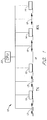
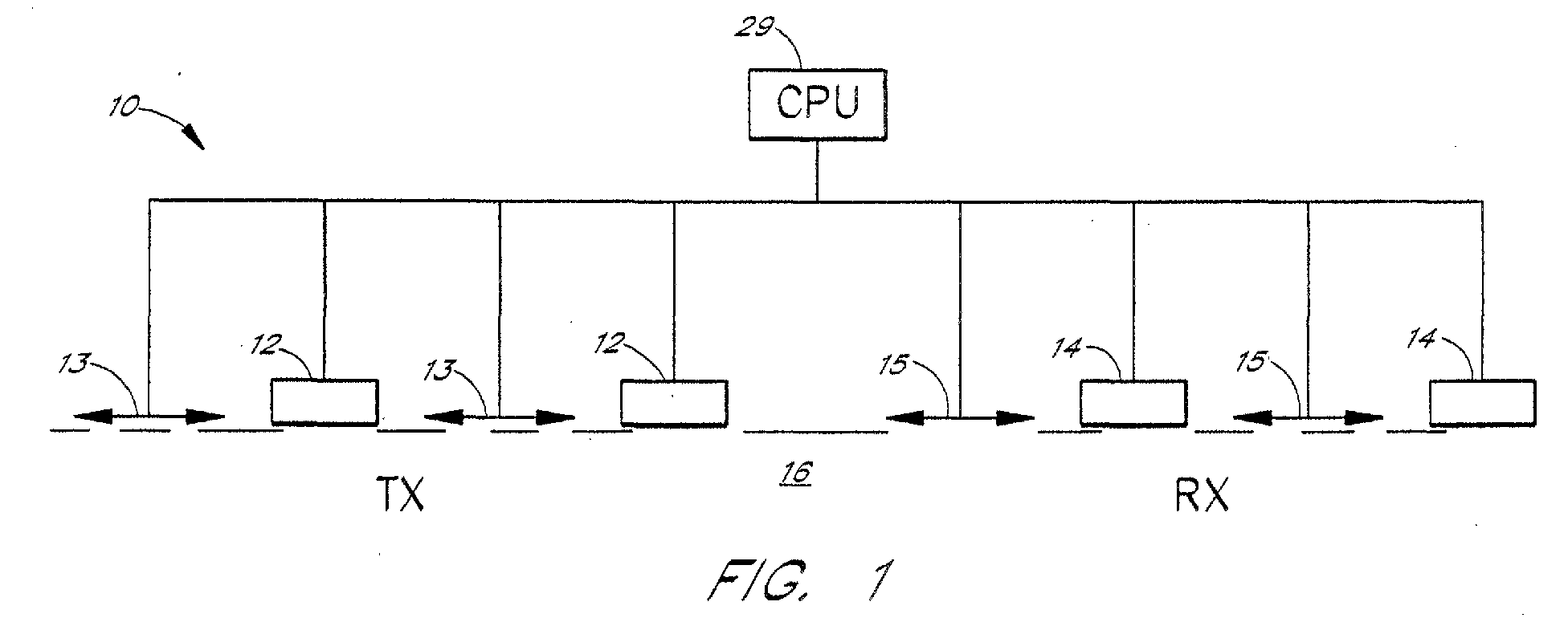
- the imaging system 10 includes induction 12 or galvanic 13 EM field transmitters and induction 14 or galvanic 15 EM field receivers placed on the surface of the examined medium 16 (FIG. 1).
- the array of receivers 14, 15 may either be one-dimensional (as shown) or two-dimensional (typically, distributed in a grid pattern across the surface of observation).
- Transmitters 12, 13 can be located arbitrarily on the surface of the examined medium 16.
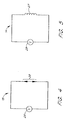
- the galvanic transmitter 13 (FIG. 2) includes the transient current source 19 connected across the pair of current electrodes 20.
- the induction transmitter 12 (FIG. 3) includes the transient current source 21 connected across a solenoid coil 22.
- the galvanic receiver 15 (FIG. 4) includes a pair of receiver electrodes 25 connected across the voltmeter 26.
- the induction receiver 14 (FIG. 5) includes a solenoid coil 27 connected across the voltmeter 28.
- galvanic devices are positioned in direct contact with the examined medium, but induction devices are operable from positions in the proximity of, but not necessarily in contact with, the examined medium.
- the central processing unit 29 (FIG. 1) operates the broad band EM holographic imaging system, as it is schematically shown by FIG. 6.
- the incoming EM field generated by a transmitter (or, as illustrated, an array TX of transmitters) is received by an array of receivers RX, and is recorded by the central processing unit 29.
- the EM field measurements are inherently reduced to numerical values. It is thus expedient to proceed with a numerical reconstruction of the volume image.
- the location of D and its anomalous conductivity a are unknown.
- the model is excited by an EM field generated by a given system of sources (transmitters TX) with an electric current density j e .
- This field is time harmonic as e -i ⁇ t and is observed by the system of receivers RX located on the surface S of the examined medium.
- the same transmitter/receiver system is re-deployed in the same spatial configuration as used for the receiving mode of operation, on the surface of the medium with the conductivity equal to the background conductivity b (background medium).
- the receivers are operated as (or replaced by) auxiliary transmitters which generate electric j e / s and magnetic j m / s currents equivalents to those evaluated from the anomalous field previously recorded by the receivers, located on the surface S : where n is the unit vector of normal to S pointing outward the examining medium, and * indicates a complex conjugate value.
- a typical imaging process thus comprises:
- imaging system 10 can be summarized as follows: An electromagnetic signal is generated by transmitters 12, 13, and is recorded by receivers 14, 15, placed on the surface of an examined medium, (for example, the earth or the body of a human being).
- the CPU system 29 analyzes the recorded field and fulfills the following numerical processes:
- the image generating method solves the minimum energy flow problem for the residual field ⁇ E ⁇ ,H ⁇ ⁇ computed as the difference between the observed field ⁇ E obs ,H obs ⁇ and numerically calculated (predicted) field ⁇ E pr ,H pr ⁇ for a constructed image.
- the measure ⁇ of the difference between the observed and predicted fields can be introduced as the energy flow of the residual field through the surfaces of observations, integrated over the frequency ⁇ :
- r', ⁇ ) ⁇ ds ⁇ S n ⁇ E a* (r, ⁇ ) ⁇ G b H (r
- the gradient of the residual field energy flow becomes:
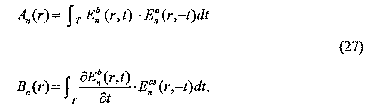
- A(r) is a cross power spectrum of background and backscattering fields, computed by the formula: A(r) ⁇ Re ⁇ ⁇ E b ( r, ⁇ ) ⁇ E as (r, ⁇ )d ⁇
- B(r) is a cross power spectrum of the time derivative of the background field and backscattering fields, computed by the formula: B(r) ⁇ Re ⁇ ⁇ (-i ⁇ )E b (r, ⁇ ) ⁇ E as (r, ⁇ )d ⁇
- ⁇ is the frequency range.
- Equation (9) provides a choice of selecting a ( r ') minimizing ⁇ : taking into account, that: where k > 0 is a scale factor determined numerically by a linear search for the minimum of the functional:
- one of the important features is the ability to produce anomalous electrical conductivity and dielectric permittivity of the target which minimize the residual field energy flow through the receivers.
- this approach is referred to as the inverse problem solution, because the residual field is the difference between the observed data and numerically predicted data, and the goal is to determine the parameters (material properties and location) of the target.
- the present method resolves this inverse problem in a new way by minimizing the residual field flow. It is realized numerically through the following three steps:
- Step 3 Constructing the volume images of anomalous conductivity ⁇ a and of anomalous permittivity ⁇ a distributions (the broad band EM holographic images) by calculating cross power spectrum A (r) of background and backscattering fields and cross power spectrum B(r) of the time derivative of the background field and backscattering field:
- the volume images of anomalous conductivity ⁇ a ( r ) and of anomalous permittivity ⁇ a ( r ) are constructed on the basis of cross power spectra A(r) and B(r) by formula (12).
- the iterations can be terminated when the functional ⁇ ( b + a ( n +1) ) reaches the required accuracy level.
- the computer of the system may be operated iteratively through the steps of: (1) updating the background field obtained in a previous iteration by adding the volume image constructed during that previous iteration; (2) repeating at least the steps of the method involving measuring (either empirically or numerically) the scattered electromagnetic field with the receivers through obtaining a next generation iteration of a volume image; and (3) repeating steps (1) and (2) until the updated background medium approximates the updated volume image.
- Regularization procedures such as described in M. S. Zhdanov and G. Hursan, 2000, 3-D electromagnetic inversion based on quasi-analytical approximation, Inverse Problems, 16, 1297-1322 can be used in the iterative process to generate a stable and resolved image.
- the method can be applied in a variety of contexts. For example, internal defects in metal or concrete constructions can be located and imaged. The method is also useful for locating and imaging underground geological structures in connection with exploration for mineral, hydrocarbons and groundwater and in connection with environmental clean up activities. A particularly promising application involves imaging internal structures of living animals, notably the internal organs of the human body.
- a normal body may serve as a reference model from which to derive a background field.
- a normal bone may serve as a reference model.
- Broad band electromagnetic imaging methods have many advantages over traditional examination methods such as X-ray. For example, broad band electromagnetic imaging methods are safer because they use electromagnetic energy that is non-ionizing. Broad band electromagnetic imaging methods are also safer because they use low-frequency energy typically in the 1-100 MHz range, lower than X-ray energy that is typically in the 1GHz range. Broad band electromagnetic imaging methods are also patient-friendly, because they do not necessarily require contact with a patient's body or compression of a patient's body.
- One of the uses of broad band electromagnetic imaging methods in the medical field is breast cancer screening.
- breast cancer screening By measuring the conductivity and dielectric permittivity of a patient's breasts, malignant tissue whose conductivity and/or dielectric permittivity are different from normal tissue can be detected.
- Broad band electromagnetic imaging methods can also be used in combination with other screening methods such as palpation or mammography to increase cancer-detection rate and to reduce false-positive rate.
- broad band electromagnetic imaging methods can also be used to examine other body parts for other diseases, including animal body parts for diseases.
- broad band electromagnetic imaging methods can be used for osteoporosis screening, to detect abnormal bones with density loss.
- the frequency of the electromagnetic energy used in the examination may be adjusted to allow desired penetration and contrast sensitivity of the body part examined. The frequency may be adjusted based on desired examination depth and density.
- Broad band electromagnetic imaging methods can also be used for nondestructive testing of technical structures.
- Technical structures such as walls, internal structural supports of buildings, aircraft structures and automobile structures are traditionally tested using eddy current testing, ultrasound testing, and other methods.
- Broad band electromagnetic imaging methods can be used to produce a 3-D image of conductivity and permittivity distribution within the examined structure. Compared to eddy current testing, which can only examine conductive structures, broad band electromagnetic methods can also examine non-conductive structures. Broad band electromagnetic methods also provide more detailed quantitative information on conductivity and permittivity distribution within the examined structure.
- a test device includes a galvanic transmitter and a galvanic receiver.
- the galvanic transmitter includes a pair of current electrodes that are connected to the examined medium. A current of electricity is sent from the current electrodes to the examined medium.
- the galvanic receiver also includes a pair of current electrodes that are connected to the examined medium. The galvanic receiver measures the electric potential difference between its two current electrodes connected to the examined medium.
- test device includes an inductive transmitter and an inductive receiver.
- the transmitter includes a solenoid induction coil. When electricity is sent to the coil, it induces a transient electromagnetic field that penetrates through the examined medium.
- the receiver also includes an induction coil. The receiver coil measures the electromagnetic field caused by electromagnetic response from the examined medium.
- the analog signals measured by the receiver are converted by a support electronics module into digital signals.
- a support electronics module is an analog-to-digital converter. The converted digital signals are then used by a computer to produce images of conductivity and/or dielectric permittivity.
- inductive transmitters and receivers have the advantage of not requiring physical contact with the examined medium.
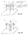
- FIGURE 7A and FIGURE 7B illustrate one embodiment of a test device 700.
- one or more transmitter coils 712 and one or more receiver coils 714 are placed along a ring 710.
- the ring 710 is placed horizontally and supported by vertical posts 720.
- the ring 710 has a diameter (such as 1-2 meters) sufficient for a patient 730 to stand in.
- the ring 710 has a diameter (such as 10-20 centimeters) sufficient for a patient to insert a body part such as a hand, a foot, or a breast into the ring 710.
- the ring 710 can be moved up and down along the vertical posts 720, so that the ring 710 can be placed to examine multiple cross sections of the patient's body 730.
- the ring 710 can be slidingly connected to the vertical posts 720, or connected to the vertical posts 720 using holes and clamps, so that the height of the ring 710 can be adjusted.
- the vertical posts 720 are adjustable in height (for example made of telescoping tubes), therefore making the ring 710 adjustable in height.
- the transmitter coils 712 are connected through the ring 710 to a power source 740.
- the receiver coils 714 are connected through the ring 710 to a support electronics module 750, which is connected to a computer 760.
- four transmitter coils 712 and four receiver coils 714 are distributed along the ring 710.
- eight transmitter coils 712 and sixteen receiver coils 714 are distributed along the ring 710.
- the transmitter coils 712 illuminate the examined medium with electromagnetic field, to be recorded by the receiver coils 714.
- the intensity of the signals has an approximate dynamic range between 100 dB to 140 dB (decibel).
- the signal frequency is between approximately 1 megahertz and approximately 10 megahertz. In another embodiment, the signal frequency is between approximately 1 megahertz and approximately 100 megahertz.
- the electromagnetic signals generated by the transmitter coils 712 are called primary signals. The primary signals interact with the examined target inside the ring 710 and result in a scattered electromagnetic field of secondary signals.
- the receiver coils 714 record the primary signals and secondary signals and send the recorded signals to the support electronics module 750 for processing.
- the support electronics module 750 converts the received analog signals into digital signals, and filters out the primary signals.
- the remaining secondary digital signals are processed by the computer 760 to produce images of conductivity and/or dielectric permittivity of the examined area.
- the ring 710 is moved up and down the vertical posts 720, an examination is performed for every ring location on the vertical posts 720, in order to generate a plurality of cross sections of conductivity and dielectric permittivity data for the patient body 730.
- each of the coils can serve as both a transmitter coil and a receiver coil.
- the coil 712 first serves as a transmitter, receives electricity from the power source 740 and illuminates the examined medium with electromagnetic field. Since electromagnetic field can at least partially remain for a short period of time, the coil 712 can then serve as a receiver and record the electromagnetic field.
- a test device is a hand held device that includes a transmitter and a receiver.
- the hand held device is placed on or in proximity to a part of a patient body.
- the hand held device is connected to a support electronics module, which is connected to a computer. After conductivity and/or permittivity data of the part of the patient body is obtained, the hand held device can be placed on or in proximity to another part of the patient body. By moving the hand held device along a patient body surface, maps of conductivity and/or permittivity can be obtained.
- test device is a scanning chamber in a form similar to a MRI scan chamber.
- a patient is placed inside the chamber.
- One of more transmitters and one or more receivers placed on the interior wall of the chamber then respectively produce and record electromagnetic fields.
- the recorded analog signals are converted by a support electronics module to digital signals.
- the digital signals are then processed by a computer to produce images of conductivity and/or permittivity.
- Still another embodiment of a test device is a scanning bed with one or more adjustable straps.
- One or more transmitters and one or more receivers are placed on each of the straps. After a patient is placed on the bed, the straps are placed on the part of the patient body that is to be examined. Transmitters and receivers then respectively produce and record electromagnetic signals.
- the straps can be removed from the bed and reattached to the bed, to be placed on another part of the patient body.
- Each embodiment of the test device is connected to a support electronics module, which is connected by wire or wirelessly to a computer.
- the receivers record a scattered electromagnetic field
- the analog signals of the field is converted by the support electronics module to digital signals.
- the computer receives the digital signals of the scattered electromagnetic field from the support electronics module, creates a simulated homogeneous background field that represents the examined background medium (such as the patient's body) without the examined target (such as the patient's breast, liver, bone, etc.), creates a simulated backscatttering anomalous field that represents an electromagnetic field obtainable by transmitting the scattered electromagnetic field from the receivers to illuminate the background medium, and produces a volume image of the conductivity and/or dielectric permittivity of the examined target.
- the computer produces the volume image by calculating cross power spectra of the background field and the backscattering field.
- the computer produces the volume image by calculating cross correlation functions between the background field and the backscattering field.
- the computer produces the volume image iteratively by:
- M. S. Zhdanov, S. Fang and G. Hursan 2000, Electromagnetic inversion using quasi-linear approximation, Geophysics, 65, No. 5, 1501-1513; M. S. Zhdanov and G. Hursan, 2000, 3-D electromagnetic inversion based on quasi-analytical approximation, Inverse Problems, 16, 1297-1322.
Landscapes
- Health & Medical Sciences (AREA)
- Life Sciences & Earth Sciences (AREA)
- Physics & Mathematics (AREA)
- Nuclear Medicine, Radiotherapy & Molecular Imaging (AREA)
- Molecular Biology (AREA)
- General Health & Medical Sciences (AREA)
- Biophysics (AREA)
- Pathology (AREA)
- Engineering & Computer Science (AREA)
- Biomedical Technology (AREA)
- Heart & Thoracic Surgery (AREA)
- Medical Informatics (AREA)
- Veterinary Medicine (AREA)
- Surgery (AREA)
- Animal Behavior & Ethology (AREA)
- Radiology & Medical Imaging (AREA)
- Public Health (AREA)
- Cardiology (AREA)
- Hematology (AREA)
- Immunology (AREA)
- Vascular Medicine (AREA)
- General Physics & Mathematics (AREA)
- Geophysics And Detection Of Objects (AREA)
- Measurement And Recording Of Electrical Phenomena And Electrical Characteristics Of The Living Body (AREA)
- Holo Graphy (AREA)
Abstract
Description

















Claims (17)
- A method for imaging an anomalous region located within a nontransparent medium of an organism, said method comprising the steps of:a. placing one or more electromagnetic transmitters in transmission contact with said medium;b. placing one or more electromagnetic receivers at receiving positions with respect to said medium;c. operating said transmitters to generate a broad band electromagnetic field, comprising a frequency domain and/or time domain electromagnetic field, whereby said generated electromagnetic field propagates through said medium to interact with said anomalous region, resulting in a scattered electromagnetic field;d. measuring said scattered electromagnetic field with said receivers;e. obtaining a background field {Eb, Hb} representative of a background medium equivalent to said medium without the presence of said anomalous region;f. obtaining a backscattering anomalous field {Eas, Has} equivalent to that obtainable by illuminating said background medium with said scattered electromagnetic field transmitted from the receiving positions of said receivers; andg. producing a broad band holographic image of said anomalous region by calculating cross power spectra of said background and said backscattering fields, or calculating cross correlation functions between said background and said backscattering fields.
- The method of Claim 1, wherein said produced image of said anomalous region identifies a medical condition of said anomalous region.
- The method of Claim 1, wherein said produced image of said anomalous region identifies an abnormal portion of said anomalous region.
- The method of Claim 1, wherein operating said transmitters to generate a broad band electromagnetic field comprises operating said transmitters to generate a broad band electromagnetic field with a frequency between approximately one megahertz and approximately ten megahertz.
- The method of Claim 1, wherein operating said transmitters to generate a broad band electromagnetic field comprises operating said transmitters to generate a broad band electromagnetic field with a frequency between approximately ten megahertz and approximately one hundred megahertz.
- The method of Claim 1, wherein operating said transmitters to generate a broad band electromagnetic field comprises operating said transmitters to generate a broad band electromagnetic field with a frequency of between approximately one megahertz and approximately one hundred megahertz.
- The method of Claim 1, wherein said broad band electromagnetic field comprises a portion of EM spectrum, wherein propagation of said portion is characterized by diffusion phenomena.
- The method of Claim 1, wherein said broad band electromagnetic field comprises a portion of EM spectrum, wherein propagation of said portion is characterized by a combination of diffusion phenomena and wave phenomena.
- A system of imaging a body part of a human or animal, comprising:an imaging ring including one or more transmitter coils and one or more receiver coils, said imaging ring configured to accommodate said body part inside said imaging ring, said transmitter coils configured to generate a broad band electromagnetic field comprising a frequency domain and/or time domain electromagnetic field, whereby said generated electromagnetic field propagates through said human or animal and interacts with said body part to result in a scattered electromagnetic field, said receiver coils configured to record said scattered electromagnetic field; anda computer configured to simulate a background field representing a hypothetical electromagnetic field of said human or animal without said body part, to compute a backscattering field representing another hypothetical electromagnetic field obtainable by transmitting said scattered electromagnetic field from said receivers, and to produce a volume image of electric conductivity and/or dielectric permittivity of said body part.
- The system of Claim 9, wherein the computer is configured to produce said volume image by calculating cross power spectra of said background field and said backscattering field.
- The system of Claim 9, wherein the computer is configured to produce said volume image by calculating cross correlation functions between said background field and said backscattering field.
- The system of Claim 9, further comprising one or more support posts connected to said imaging ring and configured to support said imaging ring.
- The system of Claim 9, wherein the computer is configured to produce said volume image iteratively by:calculating an updated (corrected) background field as electromagnetic response for the updated background medium with the complex conductivity, obtained on the previous iteration;calculating the updated residual field between this response and observed field;calculating the updated backscattering field for the updated residual field by simulating illumination of the updated background medium with electric and magnetic currents equivalent to those of the updated residual field recorded at the location of the receivers; andconstructing the updated volume images of anomalous conductivitya ( n )(r) and of anomalous permittivity εa ( n )(r) on the basis of updated cross power spectrum or cross correlation functions between said background field and said updated backscattering field, using regularization procedures.

- The system of Claim 12, wherein said support posts are adjustable in height.
- The system of Claim 12, wherein said imaging ring is adjustable in height along said support posts.
- The system of Claim 9, further comprising a converter configured to receive analog signals of said scattered electromagnetic field from said receiver coils, to convert said received analog signals into digital signals of said scattered electromagnetic field, and to transmit said digital signals to said computer.
- The system of Claim 9, wherein said receiver coils are further configured to record said generated electromagnetic field, said system further comprising a filter configured to receive said generated electromagnetic filed and said scattered electromagnetic field from said receiver coils, to filter said generated electromagnetic field from said scattered electromagnetic field, and to transmit said scattered electromagnetic field to said computer.
Applications Claiming Priority (2)
| Application Number | Priority Date | Filing Date | Title |
|---|---|---|---|
| US876262 | 1997-06-19 | ||
| US09/876,262 US6876878B2 (en) | 1996-06-26 | 2001-06-06 | Medical broad band electromagnetic holographic imaging |
Publications (2)
| Publication Number | Publication Date |
|---|---|
| EP1264576A2 true EP1264576A2 (en) | 2002-12-11 |
| EP1264576A3 EP1264576A3 (en) | 2003-08-06 |
Family
ID=25367299
Family Applications (1)
| Application Number | Title | Priority Date | Filing Date |
|---|---|---|---|
| EP02012252A Withdrawn EP1264576A3 (en) | 2001-06-06 | 2002-06-04 | Medical broad band electromagnetic holographic imaging |
Country Status (4)
| Country | Link |
|---|---|
| US (1) | US6876878B2 (en) |
| EP (1) | EP1264576A3 (en) |
| JP (1) | JP2003177656A (en) |
| CA (1) | CA2388981A1 (en) |
Cited By (2)
| Publication number | Priority date | Publication date | Assignee | Title |
|---|---|---|---|---|
| DE102005015355A1 (en) * | 2005-04-04 | 2006-11-09 | Kopp, Thomas | Electromagnetic substance excitation depth control transmit receive procedure for nuclear magnetic resonance applies maximum transmit current by parallel switching of single wire antennas |
| EP2465428A1 (en) * | 2010-12-15 | 2012-06-20 | Medielma S.r.l. | Electromagnetic detection system and method for locating tumors/calcifications in tissues |
Families Citing this family (19)
| Publication number | Priority date | Publication date | Assignee | Title |
|---|---|---|---|---|
| US7324899B2 (en) * | 2005-07-22 | 2008-01-29 | University Of Utah | Geophysical technique for mineral exploration and discrimination based on electromagnetic methods and associated systems |
| US7573381B2 (en) * | 2006-02-21 | 2009-08-11 | Karr Lawrence J | Reverse locator |
| US7592918B2 (en) * | 2006-02-21 | 2009-09-22 | Karr Lawrence J | Electronic fence mode alert system and method |
| US7791470B2 (en) * | 2006-02-21 | 2010-09-07 | Roundtrip Llc | Spin around direction and distance locator |
| US7917155B2 (en) | 2006-10-27 | 2011-03-29 | Roundtrip Llc | Location of cooperative tags with personal electronic device |
| GEP20084574B (en) * | 2007-03-16 | 2008-12-25 | Marina Shaduri | Device for gas-discharge survey for detection of malignant processes in living organisms |
| US9844347B2 (en) | 2009-02-13 | 2017-12-19 | The Ohio State University | Electromagnetic system and method |
| US20120019238A1 (en) * | 2009-03-30 | 2012-01-26 | Koninklijke Philips Electronics N.V. | Magnetic induction tomography systems with coil configuration |
| JP6305974B2 (en) | 2013-02-12 | 2018-04-04 | 国立大学法人神戸大学 | Scattering tomography method and scattering tomography apparatus |
| PT3117777T (en) | 2014-03-12 | 2020-06-17 | Integral Geometry Science Inc | Scattering tomography method and scattering tomography device |
| JP6752473B2 (en) | 2015-09-29 | 2020-09-09 | 国立大学法人神戸大学 | Imaging method and imaging device |
| US10660531B1 (en) | 2015-10-16 | 2020-05-26 | Furaxa, Inc. | Method and apparatus for non-invasive real-time biomedical imaging of neural and vascular activity |
| WO2017083317A1 (en) | 2015-11-09 | 2017-05-18 | Ohio State Innovation Foundation | Non-invasive method for detecting a deadly form of malaria |
| WO2017145154A1 (en) | 2016-02-22 | 2017-08-31 | Real View Imaging Ltd. | Wide field of view hybrid holographic display |
| US20190155033A1 (en) | 2016-02-22 | 2019-05-23 | Real View Imaging Ltd. | Holographic display |
| WO2017145155A1 (en) | 2016-02-22 | 2017-08-31 | Real View Imaging Ltd. | A method and system for displaying holographic images within a real object |
| US11663937B2 (en) | 2016-02-22 | 2023-05-30 | Real View Imaging Ltd. | Pupil tracking in an image display system |
| WO2017145158A1 (en) | 2016-02-22 | 2017-08-31 | Real View Imaging Ltd. | Zero order blocking and diverging for holographic imaging |
| US11675101B2 (en) | 2021-06-18 | 2023-06-13 | Terrasee Tech, LLC | Determining presence and depth of materials in the earth |
Family Cites Families (27)
| Publication number | Priority date | Publication date | Assignee | Title |
|---|---|---|---|---|
| US3887923A (en) | 1973-06-26 | 1975-06-03 | Us Navy | Radio-frequency holography |
| US3953822A (en) * | 1973-10-15 | 1976-04-27 | Rca Corporation | Wave-energy imaging technique |
| US4948974A (en) | 1984-06-25 | 1990-08-14 | Nelson Robert S | High resolution imaging apparatus and method for approximating scattering effects |
| US4755944A (en) * | 1986-04-14 | 1988-07-05 | Terragraf, Inc. | Method for obtaining dielectric constant and conductivity information on subsoil structure using continuous complex geotomography |
| US4852575A (en) | 1988-02-26 | 1989-08-01 | North American Philips Corporation | Ultrasound flow measurement apparatus |
| US4961428A (en) * | 1988-05-02 | 1990-10-09 | Northeastern University | Non-invasive method and apparatus for describing the electrical activity of the surface of an interior organ |
| US4945239A (en) | 1989-03-29 | 1990-07-31 | Center For Innovative Technology | Early detection of breast cancer using transillumination |
| US5072128A (en) | 1989-07-26 | 1991-12-10 | Nikon Corporation | Defect inspecting apparatus using multiple color light to detect defects |
| US5476108A (en) | 1990-04-05 | 1995-12-19 | R. J. Reynolds Tobacco Company | Method and apparatus for detecting foreign matter within a layer of tabacco |
| US5363050A (en) * | 1990-08-31 | 1994-11-08 | Guo Wendy W | Quantitative dielectric imaging system |
| US5435312A (en) * | 1991-05-31 | 1995-07-25 | Spivey; Brett A. | Acoustic imaging device |
| US5413098A (en) | 1991-12-24 | 1995-05-09 | Sextant Medical Corporation | Path constrained spectrophotometer and method for determination of spatial distribution of light or other radiation scattering and absorbing substances in a radiation scattering medium |
| US5327139A (en) | 1992-09-11 | 1994-07-05 | The Boeing Company | ID microwave holographic sensor |
| US5588032A (en) * | 1992-10-14 | 1996-12-24 | Johnson; Steven A. | Apparatus and method for imaging with wavefields using inverse scattering techniques |
| US5303710A (en) | 1992-11-03 | 1994-04-19 | The United States Of America As Represented By The Secretary Of The Navy | Apparatus for imaging an object in or through a scattering medium using coherent anti-Stokes Raman scattering |
| US5418797A (en) | 1993-01-15 | 1995-05-23 | The United States Of America As Represented By The Secretary Of The Navy | Time gated imaging through scattering material using polarization and stimulated raman amplification |
| US5373443A (en) | 1993-10-06 | 1994-12-13 | The Regents, University Of California | Method for imaging with low frequency electromagnetic fields |
| US5503150A (en) | 1994-03-10 | 1996-04-02 | Westinghouse Electric Corp. | Apparatus and method for noninvasive microwave heating of tissue |
| US5715819A (en) * | 1994-05-26 | 1998-02-10 | The Carolinas Heart Institute | Microwave tomographic spectroscopy system and method |
| US5704355A (en) | 1994-07-01 | 1998-01-06 | Bridges; Jack E. | Non-invasive system for breast cancer detection |
| US5606969A (en) | 1995-03-31 | 1997-03-04 | Brigham & Women'hospital | Methods for measuring lung function using diffused light |
| US5592170A (en) | 1995-04-11 | 1997-01-07 | Jaycor | Radar system and method for detecting and discriminating targets from a safe distance |
| US5694938A (en) * | 1995-06-07 | 1997-12-09 | The Regents Of The University Of California | Methodology and apparatus for diffuse photon mimaging |
| US5841288A (en) * | 1996-02-12 | 1998-11-24 | Microwave Imaging System Technologies, Inc. | Two-dimensional microwave imaging apparatus and methods |
| US5673050A (en) | 1996-06-14 | 1997-09-30 | Moussally; George | Three-dimensional underground imaging radar system |
| WO1997049329A1 (en) * | 1996-06-26 | 1997-12-31 | University Of Utah Research Foundation | Method of broad band electromagnetic holographic imaging |
| US5963658A (en) * | 1997-01-27 | 1999-10-05 | University Of North Carolina | Method and apparatus for detecting an abnormality within a host medium |
-
2001
- 2001-06-06 US US09/876,262 patent/US6876878B2/en not_active Expired - Lifetime
-
2002
- 2002-06-04 EP EP02012252A patent/EP1264576A3/en not_active Withdrawn
- 2002-06-05 CA CA002388981A patent/CA2388981A1/en not_active Abandoned
- 2002-06-06 JP JP2002165512A patent/JP2003177656A/en not_active Withdrawn
Cited By (3)
| Publication number | Priority date | Publication date | Assignee | Title |
|---|---|---|---|---|
| DE102005015355A1 (en) * | 2005-04-04 | 2006-11-09 | Kopp, Thomas | Electromagnetic substance excitation depth control transmit receive procedure for nuclear magnetic resonance applies maximum transmit current by parallel switching of single wire antennas |
| EP2465428A1 (en) * | 2010-12-15 | 2012-06-20 | Medielma S.r.l. | Electromagnetic detection system and method for locating tumors/calcifications in tissues |
| WO2012080300A1 (en) * | 2010-12-15 | 2012-06-21 | Medielma Srl | Electromagnetic detection system and method for locating tumors/calcifications in tissues |
Also Published As
| Publication number | Publication date |
|---|---|
| US20020062074A1 (en) | 2002-05-23 |
| US6876878B2 (en) | 2005-04-05 |
| EP1264576A3 (en) | 2003-08-06 |
| CA2388981A1 (en) | 2002-12-06 |
| JP2003177656A (en) | 2003-06-27 |
Similar Documents
| Publication | Publication Date | Title |
|---|---|---|
| US6253100B1 (en) | Method of broad band electromagnetic holographic imaging | |
| US6876878B2 (en) | Medical broad band electromagnetic holographic imaging | |
| US7550969B2 (en) | Security screening and inspection based on broadband electromagnetic holographic imaging | |
| Bevacqua et al. | Millimeter-waves breast cancer imaging via inverse scattering techniques | |
| Liu et al. | Active microwave imaging. I. 2-D forward and inverse scattering methods | |
| Gilmore et al. | Microwave biomedical data inversion using the finite-difference contrast source inversion method | |
| Henriksson et al. | Quantitative microwave imaging for breast cancer detection using a planar 2.45 GHz system | |
| CN1261259A (en) | Electromagnetical imaging and therpeutic (Emit) systems | |
| Gürbüz et al. | A nonlinear microwave breast cancer imaging approach through realistic body–breast modeling | |
| Ostadrahimi et al. | A novel microwave tomography system based on the scattering probe technique | |
| Zhu et al. | Active adjoint modeling method in microwave induced thermoacoustic tomography for breast tumor | |
| Wang | Multi-frequency holographic microwave imaging for breast lesion detection | |
| US6785570B2 (en) | System and method for analysis of a tissue | |
| Edwards et al. | Machine-learning-enabled recovery of prior information from experimental breast microwave imaging data | |
| Li et al. | Breast imaging using waveform attenuation tomography | |
| Patel | Microwave imaging for breast cancer detection using 3D level set based optimization, FDTD method and method of moments | |
| Ciocan et al. | Model‐based microwave image reconstruction: simulations and experiments: Model‐based microwave image reconstruction: simulations and experiments | |
| Bisio et al. | Brain stroke detection by microwave imaging systems: Preliminary two-dimensional numerical simulations | |
| Wang | Electromagnetic induction holography imaging for stroke detection | |
| Arduino et al. | Computational low-frequency electromagnetic dosimetry based on magnetic field measurements | |
| Wang | 3D holographic millimeter-wave imaging for concealed metallic forging objects detection | |
| Elsdon et al. | Early stage breast cancer detection using indirect microwave holography | |
| Shao et al. | An Example of Microwave Diagnosis for Knee Osteophyte by 3D Parallel FD-FDTD Approach | |
| Mondal et al. | A comprehensive study on microwave imaging system for breast cancer detection and confocal microwave imaging | |
| Dachena | Microwave Imaging of The Neck by Means of Inverse-Scattering Techniques |
Legal Events
| Date | Code | Title | Description |
|---|---|---|---|
| PUAI | Public reference made under article 153(3) epc to a published international application that has entered the european phase |
Free format text: ORIGINAL CODE: 0009012 |
|
| AK | Designated contracting states |
Kind code of ref document: A2 Designated state(s): AT BE CH CY DE DK ES FI FR GB GR IE IT LI LU MC NL PT SE TR |
|
| AX | Request for extension of the european patent |
Free format text: AL;LT;LV;MK;RO;SI |
|
| PUAL | Search report despatched |
Free format text: ORIGINAL CODE: 0009013 |
|
| AK | Designated contracting states |
Designated state(s): AT BE CH CY DE DK ES FI FR GB GR IE IT LI LU MC NL PT SE TR |
|
| AX | Request for extension of the european patent |
Extension state: AL LT LV MK RO SI |
|
| AKX | Designation fees paid | ||
| REG | Reference to a national code |
Ref country code: DE Ref legal event code: 8566 |
|
| STAA | Information on the status of an ep patent application or granted ep patent |
Free format text: STATUS: THE APPLICATION IS DEEMED TO BE WITHDRAWN |
|
| 18D | Application deemed to be withdrawn |
Effective date: 20040207 |