EP1264107B1 - Hydraulic power system - Google Patents
Hydraulic power system Download PDFInfo
- Publication number
- EP1264107B1 EP1264107B1 EP01946919A EP01946919A EP1264107B1 EP 1264107 B1 EP1264107 B1 EP 1264107B1 EP 01946919 A EP01946919 A EP 01946919A EP 01946919 A EP01946919 A EP 01946919A EP 1264107 B1 EP1264107 B1 EP 1264107B1
- Authority
- EP
- European Patent Office
- Prior art keywords
- fluid
- reservoir
- pump
- outlet
- inlet
- Prior art date
- Legal status (The legal status is an assumption and is not a legal conclusion. Google has not performed a legal analysis and makes no representation as to the accuracy of the status listed.)
- Expired - Lifetime
Links
- 239000012530 fluid Substances 0.000 claims description 124
- 238000005192 partition Methods 0.000 claims description 7
- 238000011144 upstream manufacturing Methods 0.000 claims description 7
- 230000009471 action Effects 0.000 claims description 3
- 238000000034 method Methods 0.000 claims 4
- 238000000926 separation method Methods 0.000 claims 2
- 238000010276 construction Methods 0.000 description 6
- 238000006073 displacement reaction Methods 0.000 description 4
- 230000000694 effects Effects 0.000 description 4
- 230000008901 benefit Effects 0.000 description 3
- 238000010586 diagram Methods 0.000 description 3
- 239000004033 plastic Substances 0.000 description 3
- 229920003023 plastic Polymers 0.000 description 3
- 230000005540 biological transmission Effects 0.000 description 2
- 239000002184 metal Substances 0.000 description 2
- 230000004044 response Effects 0.000 description 2
- 230000007704 transition Effects 0.000 description 2
- 230000006978 adaptation Effects 0.000 description 1
- 238000005273 aeration Methods 0.000 description 1
- 230000004888 barrier function Effects 0.000 description 1
- 230000009286 beneficial effect Effects 0.000 description 1
- 230000008859 change Effects 0.000 description 1
- 238000001816 cooling Methods 0.000 description 1
- 239000010705 motor oil Substances 0.000 description 1
- 239000003921 oil Substances 0.000 description 1
- 230000003134 recirculating effect Effects 0.000 description 1
- 230000000630 rising effect Effects 0.000 description 1
Images



Classifications
-
- F—MECHANICAL ENGINEERING; LIGHTING; HEATING; WEAPONS; BLASTING
- F04—POSITIVE - DISPLACEMENT MACHINES FOR LIQUIDS; PUMPS FOR LIQUIDS OR ELASTIC FLUIDS
- F04C—ROTARY-PISTON, OR OSCILLATING-PISTON, POSITIVE-DISPLACEMENT MACHINES FOR LIQUIDS; ROTARY-PISTON, OR OSCILLATING-PISTON, POSITIVE-DISPLACEMENT PUMPS
- F04C15/00—Component parts, details or accessories of machines, pumps or pumping installations, not provided for in groups F04C2/00 - F04C14/00
- F04C15/06—Arrangements for admission or discharge of the working fluid, e.g. constructional features of the inlet or outlet
- F04C15/062—Arrangements for supercharging the working space
-
- B—PERFORMING OPERATIONS; TRANSPORTING
- B62—LAND VEHICLES FOR TRAVELLING OTHERWISE THAN ON RAILS
- B62D—MOTOR VEHICLES; TRAILERS
- B62D5/00—Power-assisted or power-driven steering
- B62D5/06—Power-assisted or power-driven steering fluid, i.e. using a pressurised fluid for most or all the force required for steering a vehicle
- B62D5/062—Details, component parts
Definitions
- This invention relates to hydraulic pumps and more particularly to the means of handling of the fluid returned to the hydraulic reservoir used to feed the pump under high flow, high pressure conditions with low noise.
- US Patent 5,802,848 discloses a hydraulic steering system for a motor vehicle having two separate fluid return lines leading to the reservoir.
- One line is a high return flow which is fed to a nozzle within the reservoir.
- the outlet of the nozzle is supported adjacent the inlet to the steering pump.
- the momentum of the return fluid exiting the nozzle creates a venturi action at the reservoir outlet, which has the beneficial effect of aspirating additional volumes of fluid from the reservoir.
- the momentum of the return fluid together with the addition of the entrained fluid from the reservoir produces a desirable "boost" effect which provides ample feed to the pump under conditions of high flow and high pressure to prevent cavitation attributable to lack of sufficient inflow to the pump.
- the second return line delivers a fraction of the return fluid to the reservoir.
- Such fluid is permitted to dwell for a time in the reservoir chamber, during which time any undissolved air or gas bubbles contained in the secondary stream are liberated before the fluid is drawn in by the primary jet stream. Without the secondary return line, the fluid would not be sufficiently deaerated and cavitation and noise would result.
- a hydraulic system includes a hydraulic pump reservoir having a fluid outlet communicating with the inlet to the pump, a single fluid return line having a nozzle within the reservoir adjacent the outlet and operative to direct a high velocity jet flow of fluid from the single return line into the outlet and to thereby aspirate additional volumes of fluid into the inlet to achieve high flow, high pressure operation of the pump.
- the nozzle includes at least one bleed hole through which a fraction of the fluid flow escapes into the reservoir at a location upstream of the nozzle outlet and dwells for a time sufficient to liberate any entrained air or gas bubbles before being drawn into to the pump by the primary flow stream.
- the invention has the advantage of achieving, with a single return line, high velocity, high flow delivery of fluid to the pump while deaerating the fluid to minimize cavitation and noise.
- the invention has the further advantage of being readily adaptable to any hydraulic pump system calling for high velocity, high flow delivery of fluid to the pump with low noise, whether the system has a single or multiple return lines.
- multiple return lines can be converged upstream of the reservoir to provide a single high flow return line leading to the reservoir.
- the invention has the further advantage of eliminating the need and thus cost and added weight of a secondary flow return line, as is necessary with system of the above-mentioned '848 prior patent.
- a schematically represented hydraulic system 10 having a pump 12 and a reservoir 14 having a single return line 76 leading from the pump 12 to the reservoir 14.
- the pump 12 may comprise any positive fixed or variable displacement hydraulic pump including motor vehicle steering pumps, oil pumps, transmission pumps, as well as hydraulic pumps used in industrial, agricultural, heavy equipment, rail and aerospace applications, to name a few.
- the booster reservoir 14 of the invention is thus applicable to working in conjunction with virtually any positive displacement hydraulic pump to achieve high rpm, high displacement and high flow without cavitation and noise.
- the adaptation of the booster reservoir 14 is not limited to pumps having multiple fluid return lines leading to the reservoir, such as is necessary for operation of the return booster reservoir in U.S. Patent 5,802,848.
- the hydraulic booster reservoir 14 of the present invention operates on and requires only a single return line, which accounts for its ready adaption to virtually any hydraulic pump system, regardless of the number of return lines.
- FIG. 2 illustrates a schematic diagram of a particular motor vehicle hydraulic system 10 which embodies the subject single return booster reservoir 14 of the invention.
- the system 10 of Figure 2 and pump shown in Figure 3 generally comprises the system disclosed in the aforementioned U.S. Patent 5,802,848, incorporated herein by reference, but modified to include the single return line boost reservoir 14 and as decribed further below.
- the slow flow return line 66 no longer extends directly into the reservoir 14 for purposes of deaerating a fraction of the flow, but rather is merged with the high flow return line 76 to provide a single line leading into the reservoir 14 which serves both to feed the pump 12 with a high velocity jet of hydraulic fluid and to deaerate a fraction of the flow within the reservoir 14 as will be described below.
- the illustrated pump 12 of the particular hydraulic system comprises a power steering pump having a stationary housing 20, an input shaft 22 rotatably supported on the stationary housing 20, and a rotating group 24 between a non-rotating thrust plate 26 on the housing and non-rotating pressure plate 28 on the housing.
- the input shaft 22 is rotatably supported on the housing 20 and the pressure plate 28 by a pair of bearings 30.
- An end 32 of the input shaft 22 outside of the stationary housing 20 is connected to a motor (not shown) of the vehicle such that the speed of the pump, i.e., the revolutions per minute (RPM's) of the input shaft 22, is proportional to the RPM's of an element, e.g., a crankshaft, of the motor.
- RPM's revolutions per minute
- the rotating group 24 of the power steering pump 12 includes a rotor 33 rigidly attached to the input shaft 22 for rotation therewith and a plurality of radially slideable vanes 34 on the rotor 33 which cooperate with a cam surface 35 on a cam ring 36 non-rotatably secured to the housing 20 around the rotor by a plurality of dowel pins 37 (only one visible in Figure 3 of US 5802848), and with the pressure plate 28 and the thrust plate 26 defining a plurality of pump chambers (not shown) which expand and collapse as the rotor rotates with the input shaft 22.
- the expanding pump chambers sweep past a fragmentarily illustrated inlet port 38 of the power steering pump and the thrust plate 26.
- the pump 12 further includes a schematically represented internal control valve 42 which, as illustrated in Figure 3 of US 5802848, is supported in a cylindrical boss 44 of the housing 20.
- the flow control valve 42 is disposed in an internal recirculation passage 46 in the stationary housing 20 between the discharge port 40 and the inlet port 38.
- the flow control valve 42 is closed, all of the fluid expelled into the discharge port 40 is discharged from the power steering pump 12 through a schematically represented high pressure port 47 of the power steering pump connected to the discharge port through an internal branch 48 of the recirculating passage 46.
- the flow control valve 42 transitions progressively from closed to fully opened in response to an increasing pressure gradient across a restriction 50 in the internal branch 48. As the flow control valve 42 opens, progressively more fluid recirculates from the discharge port 40 directly to the inlet port 38 to maintain the flow rate from the high pressure port 47 of the power steering pump substantially constant and to induce subatmospheric pressure at the inlet port 38 to suppress cavitation. When the flow control valve is closed, there is no recirculation to suppress cavitation.
- a schematically represented internal pressure relief valve 52 of the power steering pump opens only in extraordinary circumstances.
- the system of US 5802848 and similar illustrated system 10 of the Figure 2 and 3 embodiment includes a steering assist fluid motor 16 which may be an element of a motor vehicle rack and pinion power steering gear such as described in U.S. Patent No. 4,454,801.
- the motor 16 includes a stationary cylinder 54, a piston 56 dividing the cylinder into a pair of working chambers 58a, 58b, and a rod 60 rigidly attached to the piston and linked to dirigible wheels, not shown, of the motor vehicle such that back and forth linear translation of the rod steers the dirigible wheels.
- the second fluid motor 18 may have any conventional construction and includes a rotatable output shaft 62 adapted for driving connection to an accessory of the motor vehicle such as a radiator cooling fan.
- the second fluid motor 18 is disposed in a fluid conduit 64 of the hydraulic system 10 through which flows all of the fluid discharged by the power steering pump 12 through the high pressure port 46 thereof and from which fluid energy is extracted to rotate the output shaft 62.
- a second fluid conduit 66 has an upstream end 68 at the second fluid motor 18 and a downstream end 70.
- a schematically represented proportional control valve 72 for the steering assist motor 16 is disposed in the second fluid conduit 66 and may have the construction described in the U.S. Patent 4,454,801. In the absence of manual effort at a steering hand wheel 74 of the motor vehicle connected to the proportional control valve 72, fluid in the second conduit 66 flows with little restriction through the valve.
- the proportional control valve 72 throttles fluid flow in the second conduit 66 to create a steering assist boost pressure and directs the boost pressure to one of the working chambers 58a, 58b of steering assist fluid motor while as the same time maintaining a connection between the other of the working chambers 58a, 58b and a second conduit 66 downstream of the flow control valve.
- a third fluid conduit 76 of the hydraulic system 10 has an upstream end 78 connected to the second fluid conduit 66 between the second fluid motor 18 and the proportional control valve 72 and a downstream end 80 at the reservoir 14.
- a flow control valve 82 of the hydraulic system 10 remote from the power steering pump 12 transitions progressively from closed to fully opened in response to an increasing pressure gradient across a restriction 84 in the second fluid conduit 66 downstream of the third fluid conduit 76. As the remote flow control valve 82 opens, progressively more fluid bypasses the proportional control valve 72 and flows toward the reservoir 14 through the third fluid conduit 76.
- a schematically represented pressure relief valve 86 parallel to the remote flow control valve 82 limits the maximum fluid pressure in the second fluid conduit 66 downstream of the third fluid conduit 76 and opens only in extraordinary circumstances.
- the fluid flow in the conduit 64 through the second motor 18 consists of the total flow discharged from the power steering pump 12 through the high pressure port 46 thereof.
- the remote flow control valve 82 is calibrated to divide the fluid flow from the conduit 64 into a constant flow rate fraction in the second fluid conduit 66 downstream of the third fluid conduit 76 and a variable flow rate fraction in the third fluid conduit 76.
- the fluid flow rate of the constant flow rate fraction is consistent with the flow requirements of the steering assist fluid motor 16 and is typically about 2.6 gallons per minute.
- the fluid flow rate of the variable flow rate fraction is constituted by the remainder of the fluid from the high pressure port of the power steering pump and varies with the speed of the input shaft 22 of the power steering pump in the range of input shaft speed when the internal flow control valve 42 of the power steering pump is closed.
- the fluid flow rate of the variable flow rate fraction typically may range between about 2.6 gallons per minute and 15 gallons per minute. Because the constant flow rate fraction is always substantially less than the variable flow rate fraction, the second conduit 66 constitutes a low flow branch of the hydraulic system 10 and the third conduit 76 constitutes a high flow branch of the hydraulic system.
- the illustrated vehicle hydraulic system 10 of the present invention differs from that disclosed in U.S. Patent 5,802,848 in that the downstream end 70 of the second fluid conduit 66 does not extend directly into the reservoir 14, but joins the downstream end 80 of the third fluid conduit 76 such that only a single, high flow line enters the reservoir 14.
- the multi-return line hydraulic system of U.S. Patent 5,802,848 has been modified according to the invention and as illustrated in Figure 2 and 3 to provide a single, high flow return line 76 to the reservoir 14, effectively eliminating the need for a low flow return line into the reservoir 14.
- downstream end 80 of the single fluid return line 76 extends into and communicates with an internal chamber 88 through a tubular fitting 90 of the reservoir 14 coupled to a flow-restricting nozzle 92 disposed within the chamber 88 well below the level L of the fluid within the chamber 88.
- a fluid discharge tube 94 is submerged in the fluid in the chamber 88 and has a passage 96 therein defining an outlet of the reservoir 14 in flow communication with the inlet 38 of the pump 12, such that fluid passing through outlet 96 is fed to the pump 12.
- the nozzle 92 comprises an elongate tubular member having a fluid-constricting reduced diameter discharge end 98 defining a constricted primary discharge opening 100 in the end thereof communicating with a receiving end 102 of the discharge tube 94.
- the nozzle 92 and discharge tube 94 are coaxial, although such is not necessary so long as the fluid expelled from the nozzle end 98 is directed into the receiving end 102 of the discharge tube 94.
- At least one bleed opening 104 Upstream of the discharge end 98 of the nozzle 92 there is provided at least one bleed opening 104 through which a fraction of the flow of fluid through the nozzle is discharged into the chamber 88 at a location remote from the receiving end 102 of the discharge tube 94.
- the high velocity fluid entering the nozzle 92 through the single return line 76 is constricted at the discharge end 98, developing a back pressure within the nozzle 92 which forces a fraction of the flow out of the nozzle 92 through the bleed opening104.
- the fraction of fluid escaping the bleed port 104 is preferably kept low, on the order of about 2-10% and preferably around 5% of the flow, with the remainder passing through the discharge end 98 and into the discharge tube 94 where it develops a venturi effect producing a negative atmospheric pressure at the receiving end 102 serving to aspirate or draw additional quantities of fluid from the chamber 88 into the discharge tube 94 to effectively boost the inflow of fluid to the pump 12.
- the boost effect reference may be had to the aforementioned U.S. Patent 5,802,848.
- the small fraction of the fluid flow exiting the bleed port 104 is permitted to dwell for a period within the chamber 88 during which time any entrained gas bubbles are permitted to rise to the surface of the fluid before such fluid is aspirated from the chamber 88 into the discharge tube 94 by the jet stream of return fluid exiting the discharge end 98 of the nozzle 92. Over time, all of the fluid in the closed system will eventually be discharged through the bleed opening 104 and thus will become deaerated, which has the effect of maintaining the fluid in a substantially deaerated condition to inhibit cavitation which might otherwise result from the feeding of such aerated fluid to the pump 12.
- a partition or baffle 106 is provided to form a barrier between the bleed port 104 and the receiving end 102 of the tube 94 to prevent the direct flow of the fluid from the bleed port 104 into the tube 94.
- the baffle 106 extends at least partially about the nozzle 92 at a location forwardly or downstream with respect to the main fluid flow of the bleed opening 104.
- the baffle 106 extends a distance upwardly in the chamber terminating at a free edge 108 below the level L of the fluid within the chamber 88.
- the baffle 106 can extend widthwise across the chamber 88.
- the baffle 106 thus partitions the chamber 88 preventing the fraction of fluid exiting the bleed opening 104 from being drawn into the discharge tube 94 until such time as it makes its way around the baffle 106.
- the size, location and configuration of the baffle 106 can be adjusted as necessary depending on the conditions of the particular system in which the reservoir 14 is operating. For example, systems in which the hydraulic fluid is prone to high levels of aeration may require a full width, tall baffle 106 to increase the dwell time of the fluid exiting the bleed hole 104.
- a fluid-pervious screen (not shown) may be provided across the partitioned region of the chamber 88 submerged in the fluid in such position that the hydraulic fluid passing up and over the baffle 106 is caused to pass through the screen. Small gas bubbles in the rising fluid encounter the collect on the screen, causing them to coalesce to form larger air bubbles that rise to the surface of the fluid more rapidly and efficiently.
- An alternative embodiment of the reservoir is identical to that of Figure 3 except that the passage 96 of the discharge tube 94 has a convergent portion 110 at the receiving end 102 and a divergent portion 112 at the opposite end in order to alter the flow characteristics through the discharge tube 94, if necessary, to achieve the desired aspiration of the fluid in the chamber 88.
- the baffle 106 of the previous embodiment is eliminated.
- the chamber 88 is configured to accommodate a nozzle 92 of sufficient length to permit the bleed hole 104 to be located a sufficient distance from the fluid outlet (i.e., beyond the aspiration zone of the receiving end 102 of the discharge tube 94), eliminating the need for the baffle 106.
- the bleed opening 104 may be directed upwardly or to the side in the chamber 88. When the bleed opening 104 is directed upwardly, it may be desirable to provide a deflector 114 on the baffle 106 to restrict the upward flow of the fluid exiting the bleed opening 104.
- Figure 4 shows a further embodiment which is like that of the Figure 3 embodiment, except that the nozzle 92 is provided with a porous section 116 in lieu of a single of multiple bleed hole 104.
- the porous section 116 may comprise formed rigid plastic, wove porous tubing of metal or plastics, a perforated metal or plastic tube, etc. providing numerous small openings 104 through which the fluid can flow.
- Figure 5 illustrates still a further embodiment in which the reservoir 14 may be constructed and operates in the same manner as any of the embodiments described above, but is remote from the pump 12 rather than being integral therewith.
- the remotely situated reservoir 14 of Figure 5 may be coupled by an appropriate fluid line 118 extending from the discharge tube 94 to the intake of the pump 12.
- Figures 6 and 7 illustrate yet further embodiments in which the passage 96 of the discharge tube 94 is not entirely coaxial with the nozzle 92. It is thus not essential that the passage 96 of the discharge tube 94 be entirely linear and coaxial with the nozzle. It is permissible to provide a bend or elbow 120 to change the direction of the flow, if necessary, to communicate with the intake 38 of the pump 12.
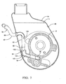
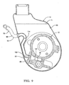
- Figures 8 and 9 show a combination pump 12 and reservoir 14 (i.e., integrated) in which the nozzle 92 extends into the chamber 88 and communicates directly with the intake 38 of the pump 12.
- the intake 38 has a conical mouth 122 to enlarge the target for the nozzle 92.
- the conical mouth 122 may be cast or machined into the body of the pump 12 as appropriate.
Landscapes
- Engineering & Computer Science (AREA)
- Chemical & Material Sciences (AREA)
- Combustion & Propulsion (AREA)
- Mechanical Engineering (AREA)
- General Engineering & Computer Science (AREA)
- Transportation (AREA)
- Details Of Reciprocating Pumps (AREA)
- Fluid-Pressure Circuits (AREA)
- Supply Devices, Intensifiers, Converters, And Telemotors (AREA)
- Details And Applications Of Rotary Liquid Pumps (AREA)
Description
Claims (13)
- A hydraulic power system (10) including: a hydraulic pump (12) having a fluid inlet (38) and a fluid outlet (40); a hydraulic fluid reservoir (14) having an internal chamber (88) for containing a supply of hydraulic fluid, an outlet (96) operatively coupled to said inlet (38) of said pump (12) for communicating fluid from said reservoir (14) to said pump (12) for operating said pump (12), and an inlet (90) for receiving return fluid into said chamber (88); and a fluid return line (76) communicating with said outlet (40) of said pump (12) and with said inlet (90) of said reservoir (14) for returning a high pressure stream of fluid from said pump (12) to said reservoir (14); said fluid return line (76) including a nozzle (92) extending into said chamber (88) through said inlet (90) having a constricted primary discharge opening (100) aligned with said outlet (96) of said reservoir (14) for directing an accelerated jet stream of the hydraulic fluid returned through said return line (76) as said reservoir outlet (96) effecting a venturi action at said reservoir outlet (96) causing additional fluid to be aspirated into said outlet (96) by said jet stream to deliver a boosted feed of the hydraulic fluid to said inlet (38) of said pump (12), and characterized by said nozzle (92) including at least one bleed hole (104) within said reservoir (14) upstream of said primary discharge opening (100) operative to discharge a fraction of the returned stream of fluid from said nozzle (92) into said chamber (88) away from said outlet (96) of said reservoir (14) to enable said fraction of said fluid to dwell in said chamber (88) for a time sufficient for natural separation from said fraction of said fluid of entrained gas bubbles before said fluid is aspirated into said outlet (96) by said jet stream.
- The system (10) of claim 1, characterized by a partition (106) disposed between said primary discharge opening (100) and said bleed hole (104) operative to divert the flow of said fraction of fluid released from said bleed hole (104) away from said outlet (96) of said reservoir (14).
- The system (10) of claim 2, characterized in that said partition (106) is mounted on said reservoir (14).
- The system (10) of claim 2, characterized in that said partition (106)is mounted on said nozzle (92).
- The system (10) of claim 2, characterized by bubble coalescing screen (107) adjacent said partition.
- The system (10) of claim 1, characterized in that said bleed hole (104) is formed in a side wall of said nozzle (92).
- The system (10) of claim 1, characterized in that said return line (76) comprises the sole source of return fluid into said reservoir (14).
- The system (10) of claim 1, characterized in that said pump (12) and said reservoir (14) are integrated such that said outlet (96) of said reservoir (14) communicated directly with said inlet (38) of said pump (12).
- The system (10) of claim 1, characterized in that said reservoir (14) is remote from said pump (12) and including a fluid line (118) extending between said outlet (96) of said reservoir (14) and said inlet (38) of said pump (12).
- The system (10) of claim 1, characterized in that said pump (12) comprises a power steering pump (12) of an automotive vehicle.
- A method of controlling the flow of fluid in a closed circuit hydraulic system (10) having a pump (12) with an inlet (38) and an outlet (40), and a fluid reservoir (14) having an inlet (90) communicating with said outlet (40) of said pump (12) and an outlet (96) communicating with said inlet (38) of said pump (12), the method comprising
fitting the inlet (90) of the reservoir (14) with a nozzle (92) extending into said reservoir (14) to a free end having a constricted primary discharge opening (100) aligned with the outlet (96) of said reservoir (14);
directing an accelerated jet stream of the hydraulic fluid from the primary discharge opening (100) at the reservoir outlet (96) effecting a venturi action at the reservoir outlet (96) causing additional fluid to be aspirated into said jet stream to deliver a boosted feed of the hydraulic fluid to the inlet (38) of the pump (12); and characterised by
providing at least one bleed hole (104) in the nozzle (92) within the reservoir (14) at a location upstream of the primary discharge opening (100) and causing a fraction of the returned stream of fluid passing through the nozzle (92) to escape into the reservoir (14) through the bleed hole (104) and to dwell in the reservoir (14) for a time sufficient for natural separation from the fraction of the fluid of entrained gas bubbles before such fluid is aspirated into the outlet by the jet stream. - The method of claim 11, characterized by providing a partition (106) between the primary discharge opening (100) and the bleed hole (104) to divert the flow of fluid from the bleed hole (104) from being drawn directly into the discharge opening (100) by the jet stream.
- The method of claim 12, characterized by passing the fluid which escapes the bleed hole (104) through a screen (107) to coalesce gas bubbles in the fluid.
Applications Claiming Priority (3)
| Application Number | Priority Date | Filing Date | Title |
|---|---|---|---|
| US17865500P | 2000-01-28 | 2000-01-28 | |
| US178655P | 2000-01-28 | ||
| PCT/US2001/001587 WO2001055596A1 (en) | 2000-01-28 | 2001-01-18 | Hydraulic power system |
Publications (2)
| Publication Number | Publication Date |
|---|---|
| EP1264107A1 EP1264107A1 (en) | 2002-12-11 |
| EP1264107B1 true EP1264107B1 (en) | 2005-11-02 |
Family
ID=22653380
Family Applications (1)
| Application Number | Title | Priority Date | Filing Date |
|---|---|---|---|
| EP01946919A Expired - Lifetime EP1264107B1 (en) | 2000-01-28 | 2001-01-18 | Hydraulic power system |
Country Status (5)
| Country | Link |
|---|---|
| US (1) | US6390783B1 (en) |
| EP (1) | EP1264107B1 (en) |
| JP (1) | JP3717850B2 (en) |
| DE (1) | DE60114583T2 (en) |
| WO (1) | WO2001055596A1 (en) |
Cited By (1)
| Publication number | Priority date | Publication date | Assignee | Title |
|---|---|---|---|---|
| US7302798B2 (en) | 2004-07-07 | 2007-12-04 | Toyoda Koki Kabushiki Kaisha | Hydraulic system, reservoir and pump suction enhancer for motor vehicle |
Families Citing this family (9)
| Publication number | Priority date | Publication date | Assignee | Title |
|---|---|---|---|---|
| US6666655B2 (en) * | 2001-05-11 | 2003-12-23 | Delphi Technologies, Inc. | Hydraulic pump nozzle and method of use |
| US6783334B2 (en) | 2002-05-31 | 2004-08-31 | Delphi Technologies, Inc. | Hydraulic pump reservoir having deaeration diffuser |
| US7086845B2 (en) * | 2003-01-23 | 2006-08-08 | Delphi Technologies, Inc. | Vane pump having an abradable coating on the rotor |
| US7591330B2 (en) * | 2005-10-07 | 2009-09-22 | Ford Global Technologies, Llc | Fluid reservoir |
| JP2007278258A (en) * | 2006-04-12 | 2007-10-25 | Kayaba Ind Co Ltd | Vane pump |
| DE102011009044B4 (en) * | 2011-01-20 | 2015-09-10 | Lukas Hydraulik Gmbh | venting device |
| DE102013204907B4 (en) * | 2012-03-23 | 2020-06-04 | GM Global Technology Operations LLC (n. d. Ges. d. Staates Delaware) | Gearbox with fluid diffuser |
| US10227951B2 (en) | 2017-02-02 | 2019-03-12 | Woodward, Inc. | Limited flow thrust reverser actuating |
| US11359404B2 (en) | 2018-11-06 | 2022-06-14 | Milwaukee Electric Tool Corporation | Door hardware locating tool |
Family Cites Families (5)
| Publication number | Priority date | Publication date | Assignee | Title |
|---|---|---|---|---|
| US4386891A (en) | 1981-04-23 | 1983-06-07 | General Motors Corporation | Rotary hydraulic vane pump with undervane passages for priming |
| US4454801A (en) | 1982-05-07 | 1984-06-19 | General Motors Corporation | Power steering gear and open center rotary valve therefor |
| US5458467A (en) * | 1994-01-14 | 1995-10-17 | Mcneil (Ohio) Corporation | Jet pump and method of operation thereof |
| US5802848A (en) * | 1997-08-28 | 1998-09-08 | General Motors Corporation | Hydraulic system for motor vehicle |
| US5943861A (en) * | 1997-12-15 | 1999-08-31 | General Motors Corporation | Hydraulic system for motor vehicle |
-
2000
- 2000-07-25 US US09/625,104 patent/US6390783B1/en not_active Expired - Fee Related
-
2001
- 2001-01-18 JP JP2001555701A patent/JP3717850B2/en not_active Expired - Fee Related
- 2001-01-18 DE DE60114583T patent/DE60114583T2/en not_active Expired - Lifetime
- 2001-01-18 EP EP01946919A patent/EP1264107B1/en not_active Expired - Lifetime
- 2001-01-18 WO PCT/US2001/001587 patent/WO2001055596A1/en not_active Ceased
Cited By (1)
| Publication number | Priority date | Publication date | Assignee | Title |
|---|---|---|---|---|
| US7302798B2 (en) | 2004-07-07 | 2007-12-04 | Toyoda Koki Kabushiki Kaisha | Hydraulic system, reservoir and pump suction enhancer for motor vehicle |
Also Published As
| Publication number | Publication date |
|---|---|
| JP3717850B2 (en) | 2005-11-16 |
| US6390783B1 (en) | 2002-05-21 |
| EP1264107A1 (en) | 2002-12-11 |
| DE60114583D1 (en) | 2005-12-08 |
| DE60114583T2 (en) | 2006-06-29 |
| JP2003521642A (en) | 2003-07-15 |
| WO2001055596A1 (en) | 2001-08-02 |
Similar Documents
| Publication | Publication Date | Title |
|---|---|---|
| US5802848A (en) | Hydraulic system for motor vehicle | |
| US6390783B1 (en) | Hydraulic pump having low aeration single return boost reservoir | |
| DE102009051473B4 (en) | Hydraulic system for a transmission with a pump inlet diffuser | |
| US3955945A (en) | Oil separator for air compressors and the like | |
| US4780050A (en) | Self-priming pump system | |
| AT399291B (en) | METHOD AND DEVICE FOR REDUCING THE GAS CONTENT OF A LIQUID | |
| US5943861A (en) | Hydraulic system for motor vehicle | |
| JP2636336B2 (en) | Centrifugal pump device with inlet reservoir | |
| JPH01391A (en) | Centrifugal pump device with inlet reservoir | |
| US7302798B2 (en) | Hydraulic system, reservoir and pump suction enhancer for motor vehicle | |
| US7281904B2 (en) | Transmission pump and filter | |
| US6287094B1 (en) | Inlet tube diffuser element for a hydraulic pump | |
| DE69909347T2 (en) | Self-priming jet pump with flow control device | |
| US4411673A (en) | Method and apparatus for degassing liquids | |
| US6116861A (en) | Filter assembly with jet pump nozzles | |
| US6783334B2 (en) | Hydraulic pump reservoir having deaeration diffuser | |
| KR20010041284A (en) | Water jet propulsion unit for use in water borne craft | |
| US3490377A (en) | Pump | |
| US4480962A (en) | Pump with inlet passages downstream and through its flow control valve | |
| EP3850219B1 (en) | Self-priming centrifugal pump | |
| EP4575273A1 (en) | Improved hydraulic system for a work vehicle and related work vehicle | |
| EP0045928A1 (en) | Power transmission | |
| KR0168551B1 (en) | Noise reduction device of power steering | |
| KR20000006053U (en) | Flow control valve of power steering steering pump | |
| JPS58218471A (en) | Flow control valve |
Legal Events
| Date | Code | Title | Description |
|---|---|---|---|
| PUAI | Public reference made under article 153(3) epc to a published international application that has entered the european phase |
Free format text: ORIGINAL CODE: 0009012 |
|
| 17P | Request for examination filed |
Effective date: 20020828 |
|
| AK | Designated contracting states |
Kind code of ref document: A1 Designated state(s): AT BE CH CY DE DK ES FI FR GB GR IE IT LI LU MC NL PT SE TR |
|
| 17Q | First examination report despatched |
Effective date: 20030618 |
|
| RBV | Designated contracting states (corrected) |
Designated state(s): DE FR GB |
|
| GRAP | Despatch of communication of intention to grant a patent |
Free format text: ORIGINAL CODE: EPIDOSNIGR1 |
|
| GRAS | Grant fee paid |
Free format text: ORIGINAL CODE: EPIDOSNIGR3 |
|
| GRAA | (expected) grant |
Free format text: ORIGINAL CODE: 0009210 |
|
| AK | Designated contracting states |
Kind code of ref document: B1 Designated state(s): DE FR GB |
|
| REG | Reference to a national code |
Ref country code: GB Ref legal event code: FG4D |
|
| REF | Corresponds to: |
Ref document number: 60114583 Country of ref document: DE Date of ref document: 20051208 Kind code of ref document: P |
|
| ET | Fr: translation filed | ||
| PLBE | No opposition filed within time limit |
Free format text: ORIGINAL CODE: 0009261 |
|
| STAA | Information on the status of an ep patent application or granted ep patent |
Free format text: STATUS: NO OPPOSITION FILED WITHIN TIME LIMIT |
|
| 26N | No opposition filed |
Effective date: 20060803 |
|
| REG | Reference to a national code |
Ref country code: FR Ref legal event code: TP |
|
| REG | Reference to a national code |
Ref country code: GB Ref legal event code: 732E Free format text: REGISTERED BETWEEN 20101028 AND 20101103 |
|
| REG | Reference to a national code |
Ref country code: DE Ref legal event code: R081 Ref document number: 60114583 Country of ref document: DE Owner name: STEERING SOLUTIONS IP HOLDING CORP., SAGINAW, US Free format text: FORMER OWNER: DELPHI TECHNOLOGIES, INC., TROY, MICH., US Effective date: 20110412 Ref country code: DE Ref legal event code: R081 Ref document number: 60114583 Country of ref document: DE Owner name: GM GLOBAL TECHNOLOGY OPERATIONS LLC (N. D. GES, US Free format text: FORMER OWNER: DELPHI TECHNOLOGIES, INC., TROY, MICH., US Effective date: 20110412 |
|
| PGFP | Annual fee paid to national office [announced via postgrant information from national office to epo] |
Ref country code: FR Payment date: 20120130 Year of fee payment: 12 |
|
| PGFP | Annual fee paid to national office [announced via postgrant information from national office to epo] |
Ref country code: GB Payment date: 20120126 Year of fee payment: 12 |
|
| REG | Reference to a national code |
Ref country code: DE Ref legal event code: R082 Ref document number: 60114583 Country of ref document: DE Representative=s name: MANITZ, FINSTERWALD & PARTNER GBR, DE |
|
| REG | Reference to a national code |
Ref country code: DE Ref legal event code: R081 Ref document number: 60114583 Country of ref document: DE Owner name: STEERING SOLUTIONS IP HOLDING CORP., US Free format text: FORMER OWNER: GM GLOBAL TECHNOLOGY OPERATIONS, INC., DETROIT, US Effective date: 20121019 Ref country code: DE Ref legal event code: R081 Ref document number: 60114583 Country of ref document: DE Owner name: GM GLOBAL TECHNOLOGY OPERATIONS LLC (N. D. GES, US Free format text: FORMER OWNER: GM GLOBAL TECHNOLOGY OPERATIONS, INC., DETROIT, US Effective date: 20121019 Ref country code: DE Ref legal event code: R082 Ref document number: 60114583 Country of ref document: DE Representative=s name: MANITZ, FINSTERWALD & PARTNER GBR, DE Effective date: 20121019 Ref country code: DE Ref legal event code: R081 Ref document number: 60114583 Country of ref document: DE Owner name: GM GLOBAL TECHNOLOGY OPERATIONS LLC (N. D. GES, US Free format text: FORMER OWNER: GM GLOBAL TECHNOLOGY OPERATIONS, INC., DETROIT, MICH., US Effective date: 20121019 Ref country code: DE Ref legal event code: R081 Ref document number: 60114583 Country of ref document: DE Owner name: STEERING SOLUTIONS IP HOLDING CORP., SAGINAW, US Free format text: FORMER OWNER: GM GLOBAL TECHNOLOGY OPERATIONS, INC., DETROIT, MICH., US Effective date: 20121019 |
|
| REG | Reference to a national code |
Ref country code: DE Ref legal event code: R082 Ref document number: 60114583 Country of ref document: DE Representative=s name: MANITZ, FINSTERWALD & PARTNER GBR, DE |
|
| PGFP | Annual fee paid to national office [announced via postgrant information from national office to epo] |
Ref country code: DE Payment date: 20130129 Year of fee payment: 13 |
|
| REG | Reference to a national code |
Ref country code: DE Ref legal event code: R081 Ref document number: 60114583 Country of ref document: DE Owner name: GM GLOBAL TECHNOLOGY OPERATIONS LLC (N. D. GES, US Free format text: FORMER OWNER: GM GLOBAL TECHNOLOGY OPERATIONS LLC (N. D. GES. D. STAATES DELAWARE), DETROIT, US Effective date: 20130313 Ref country code: DE Ref legal event code: R082 Ref document number: 60114583 Country of ref document: DE Representative=s name: MANITZ, FINSTERWALD & PARTNER GBR, DE Effective date: 20130313 Ref country code: DE Ref legal event code: R081 Ref document number: 60114583 Country of ref document: DE Owner name: STEERING SOLUTIONS IP HOLDING CORP., US Free format text: FORMER OWNER: GM GLOBAL TECHNOLOGY OPERATIONS LLC (N. D. GES. D. STAATES DELAWARE), DETROIT, US Effective date: 20130313 Ref country code: DE Ref legal event code: R081 Ref document number: 60114583 Country of ref document: DE Owner name: STEERING SOLUTIONS IP HOLDING CORP., SAGINAW, US Free format text: FORMER OWNER: GM GLOBAL TECHNOLOGY OPERATIONS LLC (N. D. GES. D. STAATES DELAWARE), DETROIT, MICH., US Effective date: 20130313 Ref country code: DE Ref legal event code: R081 Ref document number: 60114583 Country of ref document: DE Owner name: GM GLOBAL TECHNOLOGY OPERATIONS LLC (N. D. GES, US Free format text: FORMER OWNER: GM GLOBAL TECHNOLOGY OPERATIONS LLC (N. D. GES. D. STAATES DELAWARE), DETROIT, MICH., US Effective date: 20130313 |
|
| GBPC | Gb: european patent ceased through non-payment of renewal fee |
Effective date: 20130118 |
|
| REG | Reference to a national code |
Ref country code: FR Ref legal event code: ST Effective date: 20130930 |
|
| REG | Reference to a national code |
Ref country code: GB Ref legal event code: 732E Free format text: REGISTERED BETWEEN 20131010 AND 20131016 |
|
| PG25 | Lapsed in a contracting state [announced via postgrant information from national office to epo] |
Ref country code: GB Free format text: LAPSE BECAUSE OF NON-PAYMENT OF DUE FEES Effective date: 20130118 Ref country code: FR Free format text: LAPSE BECAUSE OF NON-PAYMENT OF DUE FEES Effective date: 20130131 |
|
| REG | Reference to a national code |
Ref country code: DE Ref legal event code: R119 Ref document number: 60114583 Country of ref document: DE |
|
| REG | Reference to a national code |
Ref country code: DE Ref legal event code: R119 Ref document number: 60114583 Country of ref document: DE Effective date: 20140801 |
|
| PG25 | Lapsed in a contracting state [announced via postgrant information from national office to epo] |
Ref country code: DE Free format text: LAPSE BECAUSE OF NON-PAYMENT OF DUE FEES Effective date: 20140801 |
|
| REG | Reference to a national code |
Ref country code: FR Ref legal event code: TQ Owner name: STEERING SOLUTIONS IP HOLDING CORPORATION, US Effective date: 20150723 Ref country code: FR Ref legal event code: CD Owner name: STEERING SOLUTIONS IP HOLDING CORPORATION, US Effective date: 20150723 Ref country code: FR Ref legal event code: CD Owner name: GM GLOBAL TECHNOLOGY OPERATIONS LLC, US Effective date: 20150723 Ref country code: FR Ref legal event code: TQ Owner name: GM GLOBAL TECHNOLOGY OPERATIONS LLC, US Effective date: 20150723 |