EP1264059B1 - Padlock arrangement - Google Patents
Padlock arrangement Download PDFInfo
- Publication number
- EP1264059B1 EP1264059B1 EP01913913A EP01913913A EP1264059B1 EP 1264059 B1 EP1264059 B1 EP 1264059B1 EP 01913913 A EP01913913 A EP 01913913A EP 01913913 A EP01913913 A EP 01913913A EP 1264059 B1 EP1264059 B1 EP 1264059B1
- Authority
- EP
- European Patent Office
- Prior art keywords
- cylinder lock
- fixing unit
- padlock
- cylinder
- different
- Prior art date
- Legal status (The legal status is an assumption and is not a legal conclusion. Google has not performed a legal analysis and makes no representation as to the accuracy of the status listed.)
- Expired - Lifetime
Links
- 230000007246 mechanism Effects 0.000 claims abstract description 53
- 239000000463 material Substances 0.000 claims description 5
- 229910000831 Steel Inorganic materials 0.000 claims description 3
- 239000010959 steel Substances 0.000 claims description 3
- 229910001369 Brass Inorganic materials 0.000 description 1
- 239000010951 brass Substances 0.000 description 1
- 238000010276 construction Methods 0.000 description 1
- 238000012986 modification Methods 0.000 description 1
- 230000004048 modification Effects 0.000 description 1
- 230000000717 retained effect Effects 0.000 description 1
Images

Classifications
-
- E—FIXED CONSTRUCTIONS
- E05—LOCKS; KEYS; WINDOW OR DOOR FITTINGS; SAFES
- E05B—LOCKS; ACCESSORIES THEREFOR; HANDCUFFS
- E05B63/00—Locks or fastenings with special structural characteristics
- E05B63/0056—Locks with adjustable or exchangeable lock parts
-
- E—FIXED CONSTRUCTIONS
- E05—LOCKS; KEYS; WINDOW OR DOOR FITTINGS; SAFES
- E05B—LOCKS; ACCESSORIES THEREFOR; HANDCUFFS
- E05B67/00—Padlocks; Details thereof
- E05B67/06—Shackles; Arrangement of the shackle
- E05B67/22—Padlocks with sliding shackles, with or without rotary or pivotal movement
- E05B67/24—Padlocks with sliding shackles, with or without rotary or pivotal movement with built- in cylinder locks
-
- E—FIXED CONSTRUCTIONS
- E05—LOCKS; KEYS; WINDOW OR DOOR FITTINGS; SAFES
- E05B—LOCKS; ACCESSORIES THEREFOR; HANDCUFFS
- E05B9/00—Lock casings or latch-mechanism casings ; Fastening locks or fasteners or parts thereof to the wing
- E05B9/08—Fastening locks or fasteners or parts thereof, e.g. the casings of latch-bolt locks or cylinder locks to the wing
- E05B9/082—Fastening locks or fasteners or parts thereof, e.g. the casings of latch-bolt locks or cylinder locks to the wing with concealed screws
-
- E—FIXED CONSTRUCTIONS
- E05—LOCKS; KEYS; WINDOW OR DOOR FITTINGS; SAFES
- E05B—LOCKS; ACCESSORIES THEREFOR; HANDCUFFS
- E05B9/00—Lock casings or latch-mechanism casings ; Fastening locks or fasteners or parts thereof to the wing
- E05B9/08—Fastening locks or fasteners or parts thereof, e.g. the casings of latch-bolt locks or cylinder locks to the wing
- E05B9/084—Fastening of lock cylinders, plugs or cores
-
- Y—GENERAL TAGGING OF NEW TECHNOLOGICAL DEVELOPMENTS; GENERAL TAGGING OF CROSS-SECTIONAL TECHNOLOGIES SPANNING OVER SEVERAL SECTIONS OF THE IPC; TECHNICAL SUBJECTS COVERED BY FORMER USPC CROSS-REFERENCE ART COLLECTIONS [XRACs] AND DIGESTS
- Y10—TECHNICAL SUBJECTS COVERED BY FORMER USPC
- Y10T—TECHNICAL SUBJECTS COVERED BY FORMER US CLASSIFICATION
- Y10T70/00—Locks
- Y10T70/40—Portable
- Y10T70/413—Padlocks
- Y10T70/437—Key-controlled
- Y10T70/446—Rigid shackle
- Y10T70/452—Sliding
- Y10T70/459—Both legs engaged
-
- Y—GENERAL TAGGING OF NEW TECHNOLOGICAL DEVELOPMENTS; GENERAL TAGGING OF CROSS-SECTIONAL TECHNOLOGIES SPANNING OVER SEVERAL SECTIONS OF THE IPC; TECHNICAL SUBJECTS COVERED BY FORMER USPC CROSS-REFERENCE ART COLLECTIONS [XRACs] AND DIGESTS
- Y10—TECHNICAL SUBJECTS COVERED BY FORMER USPC
- Y10T—TECHNICAL SUBJECTS COVERED BY FORMER US CLASSIFICATION
- Y10T70/00—Locks
- Y10T70/40—Portable
- Y10T70/413—Padlocks
- Y10T70/487—Parts, accessories, attachments and adjuncts
- Y10T70/489—Housings
-
- Y—GENERAL TAGGING OF NEW TECHNOLOGICAL DEVELOPMENTS; GENERAL TAGGING OF CROSS-SECTIONAL TECHNOLOGIES SPANNING OVER SEVERAL SECTIONS OF THE IPC; TECHNICAL SUBJECTS COVERED BY FORMER USPC CROSS-REFERENCE ART COLLECTIONS [XRACs] AND DIGESTS
- Y10—TECHNICAL SUBJECTS COVERED BY FORMER USPC
- Y10T—TECHNICAL SUBJECTS COVERED BY FORMER US CLASSIFICATION
- Y10T70/00—Locks
- Y10T70/40—Portable
- Y10T70/413—Padlocks
- Y10T70/487—Parts, accessories, attachments and adjuncts
- Y10T70/493—Protectors
-
- Y—GENERAL TAGGING OF NEW TECHNOLOGICAL DEVELOPMENTS; GENERAL TAGGING OF CROSS-SECTIONAL TECHNOLOGIES SPANNING OVER SEVERAL SECTIONS OF THE IPC; TECHNICAL SUBJECTS COVERED BY FORMER USPC CROSS-REFERENCE ART COLLECTIONS [XRACs] AND DIGESTS
- Y10—TECHNICAL SUBJECTS COVERED BY FORMER USPC
- Y10T—TECHNICAL SUBJECTS COVERED BY FORMER US CLASSIFICATION
- Y10T70/00—Locks
- Y10T70/70—Operating mechanism
- Y10T70/7441—Key
- Y10T70/7486—Single key
- Y10T70/7508—Tumbler type
- Y10T70/7559—Cylinder type
- Y10T70/7638—Cylinder and plug assembly
-
- Y—GENERAL TAGGING OF NEW TECHNOLOGICAL DEVELOPMENTS; GENERAL TAGGING OF CROSS-SECTIONAL TECHNOLOGIES SPANNING OVER SEVERAL SECTIONS OF THE IPC; TECHNICAL SUBJECTS COVERED BY FORMER USPC CROSS-REFERENCE ART COLLECTIONS [XRACs] AND DIGESTS
- Y10—TECHNICAL SUBJECTS COVERED BY FORMER USPC
- Y10T—TECHNICAL SUBJECTS COVERED BY FORMER US CLASSIFICATION
- Y10T70/00—Locks
- Y10T70/70—Operating mechanism
- Y10T70/7441—Key
- Y10T70/7915—Tampering prevention or attack defeating
- Y10T70/7921—Armoring
Definitions
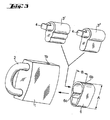
- Design variation possibilities are also enhanced if the cylinder chamber of the lock body is substantially longer than the fixing unit in the axial direction of the cylinder lock mechanism and is formed so as to accommodate different sizes and forms of cylinder lock mechanisms and fixing units.
Landscapes
- Engineering & Computer Science (AREA)
- Structural Engineering (AREA)
- Refuge Islands, Traffic Blockers, Or Guard Fence (AREA)
- Reduction Rolling/Reduction Stand/Operation Of Reduction Machine (AREA)
- Heat Treatment Of Steel (AREA)
- Paper (AREA)
- Temperature-Responsive Valves (AREA)
- Tyre Moulding (AREA)
- Eye Examination Apparatus (AREA)
- Lock And Its Accessories (AREA)
- Control For Baths (AREA)
- Traffic Control Systems (AREA)
- Slot Machines And Peripheral Devices (AREA)
- Measurement And Recording Of Electrical Phenomena And Electrical Characteristics Of The Living Body (AREA)
Abstract
Description
Claims (8)
- A padlock including a lock body (1), a lock shackle (2) movable between locking and releasing positions, and, inside the lock body, bolt means (5) for securing and releasing the shackle (2) in its locking position, and a cylinder lock mechanism (3) for controlling the bolt means (5), characterised in that the cylinder lock mechanism (3) is replaceably mounted in a separate casing-like fixing unit (6) which is detachably fixed to the lock body (1), and in that the fixing unit (6) has inner guiding surfaces (6c), which correspond to the outer shape of the cylinder lock mechanisms (3,3',3") of different type, substantially completely covering the outer shapes of the cylinder lock mechanisms to provide both radial and axial support for the cylinder lock mechanism (3,3',3'').
- A padlock according to claim 1, characterised in that the fixing unit (6) is fabricated from different material to that of the lock body (1) and/or the cylinder lock mechanism (3,3',3'').
- A padlock according to claim 1 or 2, characterised in that the fixing unit (6) is made from chilled steel.
- A padlock according to any one of the preceding claims, characterised in that the fixing unit (6) has a maximum first dimension (A) in a plane perpendicular to an axial direction of the cylinder lock mechanism (3,3',3") which is larger than a second dimension (B) perpendicular to said first dimension in said plane.
- A padlock according to any one of the preceding claims, characterised in that a key cylinder (1a) of the lock body is longer in an axial direction of the cylinder lock mechanism than the fixing unit (6) and is formed so that it is possible to install different fixing units (6) made for different sizes and forms of cylinder lock mechanism (3,3',3").
- A padlock arrangement comprising a lock body (1), a lock shackle (2) movable between locking and releasing positions, bolt means (5) for securing and releasing the shackle (2) in its locking position, and at least two cylinder lock mechanisms (3) selectively replaceably positionable in the lock body for controlling the bolt means (5), said cylinder lock mechanisms (3) being replaceably supported in at least one casing-like fixing unit (6) which is detachably fixed to the lock body (1), characterised in that the or each fixing unit (6) has inner guiding surfaces (6c), which correspond to the outer shape of at least two cylinder lock mechanisms (3,3',3"), of different type, substantially completely covering the outer shapes of the cylinder lock mechanisms and in that it is intended to provide both radial and axial support for the particular cylinder lock mechanism (3,3',3") supported in the fixing unit in each case.
- A padlock arrangement according to claim 6, characterised in that said inner guiding surfaces (6c) of the or each fixing unit (6) are formed so that they guide different kinds of said cylinder lock mechanisms (3,3',3").
- A padlock according to claim 6 or 7, characterised in that it comprises different types of fixing units (6) having different inner guiding surfaces (6c).
Applications Claiming Priority (3)
| Application Number | Priority Date | Filing Date | Title |
|---|---|---|---|
| FI20000457 | 2000-02-29 | ||
| FI20000457A FI114498B (en) | 2000-02-29 | 2000-02-29 | padlock device |
| PCT/FI2001/000198 WO2001065036A1 (en) | 2000-02-29 | 2001-02-27 | Padlock arrangement |
Publications (2)
| Publication Number | Publication Date |
|---|---|
| EP1264059A1 EP1264059A1 (en) | 2002-12-11 |
| EP1264059B1 true EP1264059B1 (en) | 2005-12-14 |
Family
ID=8557757
Family Applications (1)
| Application Number | Title | Priority Date | Filing Date |
|---|---|---|---|
| EP01913913A Expired - Lifetime EP1264059B1 (en) | 2000-02-29 | 2001-02-27 | Padlock arrangement |
Country Status (9)
| Country | Link |
|---|---|
| US (1) | US6708533B2 (en) |
| EP (1) | EP1264059B1 (en) |
| AT (1) | ATE312987T1 (en) |
| AU (1) | AU2001239326A1 (en) |
| CA (1) | CA2400061C (en) |
| DE (1) | DE60115864T2 (en) |
| DK (1) | DK1264059T3 (en) |
| FI (1) | FI114498B (en) |
| WO (1) | WO2001065036A1 (en) |
Cited By (2)
| Publication number | Priority date | Publication date | Assignee | Title |
|---|---|---|---|---|
| CN102392565A (en) * | 2011-10-28 | 2012-03-28 | 金泰祥精密五金(昆山)有限公司 | Padlock |
| US10995521B2 (en) | 2018-06-27 | 2021-05-04 | Strattec Security Corporation | Linear lock |
Families Citing this family (12)
| Publication number | Priority date | Publication date | Assignee | Title |
|---|---|---|---|---|
| US7278283B2 (en) * | 2004-04-27 | 2007-10-09 | Abus August Bremicker Soehne Kg | Padlock |
| US20060185404A1 (en) * | 2005-02-18 | 2006-08-24 | Hansen Randall C | Codeable padlock |
| USD578864S1 (en) * | 2007-04-13 | 2008-10-21 | Master Lock Company Llc | Lock |
| USD577278S1 (en) * | 2007-04-13 | 2008-09-23 | Master Lock Company Llc | Lock |
| US20100031717A1 (en) * | 2008-08-11 | 2010-02-11 | Lurie Alan E | Interchangable core adapter and method of using same |
| USD592485S1 (en) | 2008-09-25 | 2009-05-19 | Master Lock Company Llc | Lock |
| US8806905B2 (en) * | 2012-04-19 | 2014-08-19 | Master Lock Company Llc | Padlock assembly |
| USD703024S1 (en) | 2012-08-28 | 2014-04-22 | Master Lock Company Llc | Lock |
| US8850858B2 (en) * | 2012-12-06 | 2014-10-07 | Master Lock Company Llc | Lock subassembly |
| IT201800003005A1 (en) * | 2018-02-23 | 2019-08-23 | Pba Spa | HANDLE UNIT WITH LOCK, PARTICULARLY FOR A GLASS DOOR |
| WO2020173986A1 (en) * | 2019-02-26 | 2020-09-03 | Mavako Aps | A lock for several different cylinder lock types and a method for assembly of the lock |
| DE102020126124A1 (en) * | 2020-10-06 | 2022-04-07 | ABUS August Bremicker Söhne Kommanditgesellschaft | Padlock basic kit and padlock system |
Family Cites Families (18)
| Publication number | Priority date | Publication date | Assignee | Title |
|---|---|---|---|---|
| US2834195A (en) | 1955-08-31 | 1958-05-13 | American Locker Co | Multi-barrel lock |
| US3800570A (en) * | 1972-04-06 | 1974-04-02 | S Kaplan | Locking mechanism |
| US4112715A (en) | 1975-09-29 | 1978-09-12 | Klaus W. Gartner | Padlock |
| US4138868A (en) * | 1977-08-19 | 1979-02-13 | Richards Sr Frederick F | Replaceable cylinder padlock |
| US4132092A (en) * | 1978-04-18 | 1979-01-02 | Chicago Lock Co. | Protective cover for a handle lock |
| US4180996A (en) | 1978-06-19 | 1980-01-01 | Master Lock Company | Padlock cylinder retainer block securing means |
| IL59705A (en) | 1980-03-25 | 1982-11-30 | Bahry Abraham | Padlock |
| US4290279A (en) | 1980-07-14 | 1981-09-22 | Unican Security Systems, Ltd. | Padlock with interchangeable cylinder |
| US4530223A (en) * | 1982-11-01 | 1985-07-23 | Medeco Security Locks, Inc. | Guard for key cylinder |
| US4545223A (en) | 1983-02-07 | 1985-10-08 | Oy Wartsila Ab | Padlock |
| SE466022B (en) * | 1987-12-22 | 1991-12-02 | Assa Ab | ACCESS TO CYLINDERLAST |
| US5186029A (en) * | 1991-09-27 | 1993-02-16 | Fort Lock Corporation | Padlock |
| US5174136A (en) * | 1991-10-04 | 1992-12-29 | Thwing Randy L | Dual function padlock with removable cylinder mechanism |
| US5233851A (en) * | 1992-03-30 | 1993-08-10 | Florian David W | Housing and adaptor for interchangeable core and insert cylinders |
| US5572890A (en) * | 1994-10-14 | 1996-11-12 | American Lock Company | High security lock system including cover plate |
| US5730008A (en) * | 1995-10-11 | 1998-03-24 | Case; Willard L. | Snowmobile track lock |
| US5921116A (en) * | 1997-02-26 | 1999-07-13 | Bruce L. Adams | Vehicle pedal lock |
| US6240754B1 (en) * | 1999-06-24 | 2001-06-05 | Steven D. Petersen | Vehicle security device |
-
2000
- 2000-02-29 FI FI20000457A patent/FI114498B/en not_active IP Right Cessation
-
2001
- 2001-02-27 EP EP01913913A patent/EP1264059B1/en not_active Expired - Lifetime
- 2001-02-27 WO PCT/FI2001/000198 patent/WO2001065036A1/en not_active Ceased
- 2001-02-27 DK DK01913913T patent/DK1264059T3/en active
- 2001-02-27 AT AT01913913T patent/ATE312987T1/en not_active IP Right Cessation
- 2001-02-27 US US10/204,105 patent/US6708533B2/en not_active Expired - Lifetime
- 2001-02-27 CA CA002400061A patent/CA2400061C/en not_active Expired - Fee Related
- 2001-02-27 DE DE60115864T patent/DE60115864T2/en not_active Expired - Lifetime
- 2001-02-27 AU AU2001239326A patent/AU2001239326A1/en not_active Abandoned
Cited By (3)
| Publication number | Priority date | Publication date | Assignee | Title |
|---|---|---|---|---|
| CN102392565A (en) * | 2011-10-28 | 2012-03-28 | 金泰祥精密五金(昆山)有限公司 | Padlock |
| CN102392565B (en) * | 2011-10-28 | 2013-07-17 | 金泰祥精密五金(昆山)有限公司 | Padlock |
| US10995521B2 (en) | 2018-06-27 | 2021-05-04 | Strattec Security Corporation | Linear lock |
Also Published As
| Publication number | Publication date |
|---|---|
| FI20000457A0 (en) | 2000-02-29 |
| DE60115864T2 (en) | 2006-07-27 |
| US6708533B2 (en) | 2004-03-23 |
| DE60115864D1 (en) | 2006-01-19 |
| DK1264059T3 (en) | 2006-05-08 |
| EP1264059A1 (en) | 2002-12-11 |
| FI20000457L (en) | 2001-08-29 |
| AU2001239326A1 (en) | 2001-09-12 |
| FI114498B (en) | 2004-10-29 |
| CA2400061A1 (en) | 2001-09-07 |
| ATE312987T1 (en) | 2005-12-15 |
| US20030121295A1 (en) | 2003-07-03 |
| WO2001065036A1 (en) | 2001-09-07 |
| CA2400061C (en) | 2008-11-18 |
Similar Documents
| Publication | Publication Date | Title |
|---|---|---|
| US6708533B2 (en) | Padlock arrangement | |
| US5666835A (en) | Key and installation double cylinder for a security lock | |
| EP1047854B1 (en) | Padlock | |
| AU679946B2 (en) | Locking apparatus | |
| US6708539B1 (en) | Lock with removable core | |
| US5469727A (en) | Electronic lock cylinder | |
| AU693369B2 (en) | Removable core cylinder lock | |
| US10533345B2 (en) | Electronic locking device | |
| US5916283A (en) | Key ring lock assembly | |
| US5138856A (en) | Anti-pick lock | |
| EP0611027B1 (en) | Padlock | |
| AU2012210778B2 (en) | Padlock | |
| AU2021356030A1 (en) | Padlock basic assembly kit and padlock system | |
| AU2008217735B2 (en) | Lock device | |
| US4528828A (en) | Padlock | |
| US8245547B1 (en) | Padlock | |
| AU2019204274B2 (en) | Padlock | |
| US6722171B1 (en) | Assembled lock cylinder for door locks | |
| CZ282240B6 (en) | Cylindrical lock | |
| CN110388141A (en) | For switch fixed padlock | |
| GB2413152A (en) | Cylinder lock with master key capability | |
| RU2004111503A (en) | PROTECTIVE LOCK WITH A DOUBLE-KEY KEY FOR HOUSING DOORS OR ANYTHING, KEY OR BILLET FOR KEY FOR THIS LOCK | |
| GB2343700A (en) | Padlock with two-part body | |
| RU2241813C1 (en) | Lock | |
| KR0138546B1 (en) | Lock and key |
Legal Events
| Date | Code | Title | Description |
|---|---|---|---|
| PUAI | Public reference made under article 153(3) epc to a published international application that has entered the european phase |
Free format text: ORIGINAL CODE: 0009012 |
|
| 17P | Request for examination filed |
Effective date: 20020816 |
|
| AK | Designated contracting states |
Kind code of ref document: A1 Designated state(s): AT BE CH CY DE DK ES FI FR GB GR IE IT LI LU MC NL PT SE TR |
|
| AX | Request for extension of the european patent |
Free format text: AL;LT;LV;MK;RO;SI |
|
| 17Q | First examination report despatched |
Effective date: 20040804 |
|
| GRAP | Despatch of communication of intention to grant a patent |
Free format text: ORIGINAL CODE: EPIDOSNIGR1 |
|
| GRAS | Grant fee paid |
Free format text: ORIGINAL CODE: EPIDOSNIGR3 |
|
| GRAA | (expected) grant |
Free format text: ORIGINAL CODE: 0009210 |
|
| AK | Designated contracting states |
Kind code of ref document: B1 Designated state(s): AT BE CH CY DE DK ES FI FR GB GR IE IT LI LU MC NL PT SE TR |
|
| PG25 | Lapsed in a contracting state [announced via postgrant information from national office to epo] |
Ref country code: LI Free format text: LAPSE BECAUSE OF FAILURE TO SUBMIT A TRANSLATION OF THE DESCRIPTION OR TO PAY THE FEE WITHIN THE PRESCRIBED TIME-LIMIT Effective date: 20051214 Ref country code: AT Free format text: LAPSE BECAUSE OF FAILURE TO SUBMIT A TRANSLATION OF THE DESCRIPTION OR TO PAY THE FEE WITHIN THE PRESCRIBED TIME-LIMIT Effective date: 20051214 Ref country code: FI Free format text: LAPSE BECAUSE OF FAILURE TO SUBMIT A TRANSLATION OF THE DESCRIPTION OR TO PAY THE FEE WITHIN THE PRESCRIBED TIME-LIMIT Effective date: 20051214 Ref country code: BE Free format text: LAPSE BECAUSE OF FAILURE TO SUBMIT A TRANSLATION OF THE DESCRIPTION OR TO PAY THE FEE WITHIN THE PRESCRIBED TIME-LIMIT Effective date: 20051214 Ref country code: CH Free format text: LAPSE BECAUSE OF FAILURE TO SUBMIT A TRANSLATION OF THE DESCRIPTION OR TO PAY THE FEE WITHIN THE PRESCRIBED TIME-LIMIT Effective date: 20051214 |
|
| REG | Reference to a national code |
Ref country code: GB Ref legal event code: FG4D |
|
| REG | Reference to a national code |
Ref country code: CH Ref legal event code: EP |
|
| REG | Reference to a national code |
Ref country code: IE Ref legal event code: FG4D |
|
| REF | Corresponds to: |
Ref document number: 60115864 Country of ref document: DE Date of ref document: 20060119 Kind code of ref document: P |
|
| PG25 | Lapsed in a contracting state [announced via postgrant information from national office to epo] |
Ref country code: IE Free format text: LAPSE BECAUSE OF NON-PAYMENT OF DUE FEES Effective date: 20060227 |
|
| PG25 | Lapsed in a contracting state [announced via postgrant information from national office to epo] |
Ref country code: MC Free format text: LAPSE BECAUSE OF NON-PAYMENT OF DUE FEES Effective date: 20060228 Ref country code: LU Free format text: LAPSE BECAUSE OF NON-PAYMENT OF DUE FEES Effective date: 20060228 |
|
| PG25 | Lapsed in a contracting state [announced via postgrant information from national office to epo] |
Ref country code: GR Free format text: LAPSE BECAUSE OF FAILURE TO SUBMIT A TRANSLATION OF THE DESCRIPTION OR TO PAY THE FEE WITHIN THE PRESCRIBED TIME-LIMIT Effective date: 20060314 |
|
| PG25 | Lapsed in a contracting state [announced via postgrant information from national office to epo] |
Ref country code: ES Free format text: LAPSE BECAUSE OF FAILURE TO SUBMIT A TRANSLATION OF THE DESCRIPTION OR TO PAY THE FEE WITHIN THE PRESCRIBED TIME-LIMIT Effective date: 20060325 |
|
| REG | Reference to a national code |
Ref country code: SE Ref legal event code: TRGR |
|
| REG | Reference to a national code |
Ref country code: DK Ref legal event code: T3 |
|
| PG25 | Lapsed in a contracting state [announced via postgrant information from national office to epo] |
Ref country code: PT Free format text: LAPSE BECAUSE OF FAILURE TO SUBMIT A TRANSLATION OF THE DESCRIPTION OR TO PAY THE FEE WITHIN THE PRESCRIBED TIME-LIMIT Effective date: 20060515 |
|
| REG | Reference to a national code |
Ref country code: CH Ref legal event code: PL |
|
| ET | Fr: translation filed | ||
| PLBE | No opposition filed within time limit |
Free format text: ORIGINAL CODE: 0009261 |
|
| STAA | Information on the status of an ep patent application or granted ep patent |
Free format text: STATUS: NO OPPOSITION FILED WITHIN TIME LIMIT |
|
| 26N | No opposition filed |
Effective date: 20060915 |
|
| REG | Reference to a national code |
Ref country code: IE Ref legal event code: MM4A |
|
| PG25 | Lapsed in a contracting state [announced via postgrant information from national office to epo] |
Ref country code: TR Free format text: LAPSE BECAUSE OF FAILURE TO SUBMIT A TRANSLATION OF THE DESCRIPTION OR TO PAY THE FEE WITHIN THE PRESCRIBED TIME-LIMIT Effective date: 20051214 |
|
| PG25 | Lapsed in a contracting state [announced via postgrant information from national office to epo] |
Ref country code: CY Free format text: LAPSE BECAUSE OF FAILURE TO SUBMIT A TRANSLATION OF THE DESCRIPTION OR TO PAY THE FEE WITHIN THE PRESCRIBED TIME-LIMIT Effective date: 20051214 |
|
| REG | Reference to a national code |
Ref country code: FR Ref legal event code: PLFP Year of fee payment: 16 |
|
| REG | Reference to a national code |
Ref country code: FR Ref legal event code: PLFP Year of fee payment: 17 |
|
| PGFP | Annual fee paid to national office [announced via postgrant information from national office to epo] |
Ref country code: DE Payment date: 20170221 Year of fee payment: 17 Ref country code: FR Payment date: 20170112 Year of fee payment: 17 Ref country code: SE Payment date: 20170213 Year of fee payment: 17 |
|
| PGFP | Annual fee paid to national office [announced via postgrant information from national office to epo] |
Ref country code: NL Payment date: 20170210 Year of fee payment: 17 Ref country code: DK Payment date: 20170210 Year of fee payment: 17 Ref country code: GB Payment date: 20170222 Year of fee payment: 17 |
|
| PGFP | Annual fee paid to national office [announced via postgrant information from national office to epo] |
Ref country code: IT Payment date: 20170221 Year of fee payment: 17 |
|
| REG | Reference to a national code |
Ref country code: DE Ref legal event code: R119 Ref document number: 60115864 Country of ref document: DE |
|
| REG | Reference to a national code |
Ref country code: DK Ref legal event code: EBP Effective date: 20180228 |
|
| REG | Reference to a national code |
Ref country code: SE Ref legal event code: EUG |
|
| REG | Reference to a national code |
Ref country code: NL Ref legal event code: MM Effective date: 20180301 |
|
| GBPC | Gb: european patent ceased through non-payment of renewal fee |
Effective date: 20180227 |
|
| PG25 | Lapsed in a contracting state [announced via postgrant information from national office to epo] |
Ref country code: SE Free format text: LAPSE BECAUSE OF NON-PAYMENT OF DUE FEES Effective date: 20180228 |
|
| REG | Reference to a national code |
Ref country code: FR Ref legal event code: ST Effective date: 20181031 |
|
| PG25 | Lapsed in a contracting state [announced via postgrant information from national office to epo] |
Ref country code: NL Free format text: LAPSE BECAUSE OF NON-PAYMENT OF DUE FEES Effective date: 20180301 |
|
| PG25 | Lapsed in a contracting state [announced via postgrant information from national office to epo] |
Ref country code: DK Free format text: LAPSE BECAUSE OF NON-PAYMENT OF DUE FEES Effective date: 20180228 Ref country code: DE Free format text: LAPSE BECAUSE OF NON-PAYMENT OF DUE FEES Effective date: 20180901 |
|
| PG25 | Lapsed in a contracting state [announced via postgrant information from national office to epo] |
Ref country code: GB Free format text: LAPSE BECAUSE OF NON-PAYMENT OF DUE FEES Effective date: 20180227 Ref country code: IT Free format text: LAPSE BECAUSE OF NON-PAYMENT OF DUE FEES Effective date: 20180227 Ref country code: FR Free format text: LAPSE BECAUSE OF NON-PAYMENT OF DUE FEES Effective date: 20180228 |