EP1263259A2 - Method of managing the traffic protection in OMS-SPRING ring networks - Google Patents
Method of managing the traffic protection in OMS-SPRING ring networks Download PDFInfo
- Publication number
- EP1263259A2 EP1263259A2 EP02291179A EP02291179A EP1263259A2 EP 1263259 A2 EP1263259 A2 EP 1263259A2 EP 02291179 A EP02291179 A EP 02291179A EP 02291179 A EP02291179 A EP 02291179A EP 1263259 A2 EP1263259 A2 EP 1263259A2
- Authority
- EP
- European Patent Office
- Prior art keywords
- span
- ring
- wavelength
- network
- path
- Prior art date
- Legal status (The legal status is an assumption and is not a legal conclusion. Google has not performed a legal analysis and makes no representation as to the accuracy of the status listed.)
- Withdrawn
Links
Images








Classifications
-
- H—ELECTRICITY
- H04—ELECTRIC COMMUNICATION TECHNIQUE
- H04J—MULTIPLEX COMMUNICATION
- H04J14/00—Optical multiplex systems
- H04J14/02—Wavelength-division multiplex systems
- H04J14/0287—Protection in WDM systems
- H04J14/0289—Optical multiplex section protection
- H04J14/0291—Shared protection at the optical multiplex section (1:1, n:m)
-
- H—ELECTRICITY
- H04—ELECTRIC COMMUNICATION TECHNIQUE
- H04J—MULTIPLEX COMMUNICATION
- H04J14/00—Optical multiplex systems
- H04J14/02—Wavelength-division multiplex systems
- H04J14/0227—Operation, administration, maintenance or provisioning [OAMP] of WDM networks, e.g. media access, routing or wavelength allocation
-
- H—ELECTRICITY
- H04—ELECTRIC COMMUNICATION TECHNIQUE
- H04J—MULTIPLEX COMMUNICATION
- H04J14/00—Optical multiplex systems
- H04J14/02—Wavelength-division multiplex systems
- H04J14/0227—Operation, administration, maintenance or provisioning [OAMP] of WDM networks, e.g. media access, routing or wavelength allocation
- H04J14/0241—Wavelength allocation for communications one-to-one, e.g. unicasting wavelengths
-
- H—ELECTRICITY
- H04—ELECTRIC COMMUNICATION TECHNIQUE
- H04J—MULTIPLEX COMMUNICATION
- H04J14/00—Optical multiplex systems
- H04J14/02—Wavelength-division multiplex systems
- H04J14/0278—WDM optical network architectures
- H04J14/0283—WDM ring architectures
-
- H—ELECTRICITY
- H04—ELECTRIC COMMUNICATION TECHNIQUE
- H04Q—SELECTING
- H04Q11/00—Selecting arrangements for multiplex systems
- H04Q11/0001—Selecting arrangements for multiplex systems using optical switching
- H04Q11/0062—Network aspects
-
- H—ELECTRICITY
- H04—ELECTRIC COMMUNICATION TECHNIQUE
- H04Q—SELECTING
- H04Q11/00—Selecting arrangements for multiplex systems
- H04Q11/0001—Selecting arrangements for multiplex systems using optical switching
- H04Q11/0062—Network aspects
- H04Q2011/0073—Provisions for forwarding or routing, e.g. lookup tables
-
- H—ELECTRICITY
- H04—ELECTRIC COMMUNICATION TECHNIQUE
- H04Q—SELECTING
- H04Q11/00—Selecting arrangements for multiplex systems
- H04Q11/0001—Selecting arrangements for multiplex systems using optical switching
- H04Q11/0062—Network aspects
- H04Q2011/0079—Operation or maintenance aspects
- H04Q2011/0081—Fault tolerance; Redundancy; Recovery; Reconfigurability
-
- H—ELECTRICITY
- H04—ELECTRIC COMMUNICATION TECHNIQUE
- H04Q—SELECTING
- H04Q11/00—Selecting arrangements for multiplex systems
- H04Q11/0001—Selecting arrangements for multiplex systems using optical switching
- H04Q11/0062—Network aspects
- H04Q2011/009—Topology aspects
- H04Q2011/0092—Ring
Definitions
- the present invention relates to the management of optical networks arranged in a ring-configuration, and in particular to a method of managing the traffic protection in OMS-SPRING ring networks, wherein the change of allocation of the wavelengths in the traffic transit nodes is provided.
- OMS-SPRING ring optical networks Optical Multiplex Section-Shared Protection Ring
- a shared protection mechanism is implementable which allows the automatic restoration of traffic in the presence of interchange causes (defects or failures in the connection fibers and/or in the optical elements which operate for the elaboration of the multiplexed optical signal).
- the OMS-SPRING networks can implement the automatic restoration of traffic through the synchronized re-routing of said traffic, which is possibly activated by each node of the configurated ring, and to be considered as a part of the protection scheme owing to the interchange reasons detected by the node itself. This operation is implementable through a protocol consisting of messages continuously interchanged between adjacent nodes.
- connection matrices are present in each network element forming the optical ring network.
- the following re-configuration actions of connection matrices are defined, which matrices are present in the nodes of the ring network, wherein the OMS-SPRING scheme is configurated:
- All the above said protection processes are of the "dual ended” type, that is with appropriate synchronization of the bridge and switch actions which are obtainable through a signaling protocol operating between the nodes of the network wherein the OMS-SPRING protection scheme is configurated, and through which the nodes adjacent to the span affected by an interchange cause (both span and ring), which nodes could be defined as “switching nodes", are signaling reciprocally the reason and the performed actions.
- the aim of the present invention is not to define the syntax and the structure of the signaling protocol to be utilized for the management of the above mentioned protection processes (span switch, near end ring switch, far end ring switch), nevertheless, it is assumed that - whichever be the protocol utilized - at least the following information are to be interchanged between the nodes belonging to the protection scheme: Reason of the request, Source Node, Destination Node, Direction of Communication, Status of Protection.
- Reason of the request Source Node
- Destination Node Destination Node
- Direction of Communication Status of Protection.
- the BR&SW actions can be implemented by the involved nodes, if the cause of the request is a failure classified at high priority (for example the break of a fiber and/or of a component) and the Status of protection indicates that no action has been implemented with the aim of optimizing the opeartion time of the protection mechanism and of limiting the traffic loss.
- a failure classified at high priority for example the break of a fiber and/or of a component
- each node of the ring receives, together with the configuration data, the information about the ring topology (or "ring map"), wherein the nodes forming the network are indicated with the relevant ID, as well as their position.
- the OMS-SPRING ring networks can foresee a mechanism named "Wavelength Interchange", shortly WLI.
- WLI it is indicated the configuration of a data traffic in a given ring network by allowing to such a traffic, which is carried in the n-th wavelength of OMS, to pass through a network element which is able to elaborate the protocol utilized for signaling, occupying numbers of ⁇ which are different at the input and the output.
- the advantage is a higher flexibility in the traffic allocation on the line resources and, therefore, an efficient band exploitation.
- span switch shows no implications which are relevant to the WLI mechanism: the span switch is managed within the span itself by both the end nodes.
- the main object of the present invention is to indicate a method of managing the ring switch near end and ring switch far end protection processes, when the generic data flow, allocated on a protected high priority wavelength, has been allocated on wavelengths which are different at the input and output of a generic node of the ring network which elaborates the signaling protocol utilized by the protection scheme.
- the basic idea of the present invention consists essentially in protecting the NT traffic by assigning, in case of a single failure of ring type, the wavelengths of the ET channels chosen according to the effective location of the failure.
- the criterion is the same both with the near end and far end processes; as already defined, the location of the BR&SW action in both the types of process is quite different.
- the low priority wavelengths to be utilized for the protection are chosen according to appropriate criteria.
- the representation of two or four fiber ring networks is made only for example and on the basis of the currently used network topologies. It should be appreciated also that the method described is in principle applicable to topologies which consider also a number which is different from two or four physical carriers (fibers) utilized for the connection of the various ring network nodes: in particular, there is nothing against the use of the method described for single fiber rings, wherein different (working and protection) wavelengths in a bidirectional way are allocated. Further, the numbers assigned to the wavelengths shown in the examples is to be considered only for information and non-limiting.
- the working capacity (consisting of working wavelengths or " ⁇ WK ”) has been indicated by the half-arrows continuously bordered in the arrows which represent the connections between the ring nodes, while the protection capacity (consisting in protecting wavelengths or " ⁇ PR ”) has been indicated by half-arrows bordered by fine broken lines.
- the working fibers (carrying the ⁇ WK ) have been indicated by continuously bordered arrows, while the protection fibers (carrying the ⁇ PR ) have been indicated by arrows bordered by broken lines.
- the ring which has been used to describe the present invention comprises, both in the two- and four-fiber schemes, six network elements or nodes, indicated by rectangles and numbered with the respective numbers (from 1 to 6). Of each node the West (W) and East (E) sides are indicated. "Span” is a fiber length between two nodes, for example the fiber length between the nodes 1 and 2 or the fiber length between the nodes 5 and 6.
- WLI Wavelength Interchange
- the basic idea of the present invention consists substantially in protecting the NT traffic by assigning, in case of single interchange cause of ring type, the wavelengths of the ET channels chosen according to the effective location of the interchange cause.
- the mentioned criterion is the same both with near end and far end process; as already defined, the location of the BR&SW action in both the types of process is quite different.
- the wavelengths of the ET channels to be utilized for the protection are to be chosen according to proper criteria.
- the nodes adjacent to said span enter the switching status and are defined switching nodes.
- the switching nodes will issue proper signals which travel through the ring in opposite directions.
- the BR&SW action is implemented:
- this activity defines the series of re-routable data flows, namely all the data flows, the nominal route of which includes the span affected by a failure.
- the other nodes of the ring are, in both the cases, in the Pass-Through status and implement the pass-through of the protecting wavelengths ( ⁇ PR ) and of the signaling generated by the switching nodes as well.
- the BR&SW action represented by the ring switch near end or far end is implemented by utilizing the protecting wavelength ( ⁇ PR ) corresponding to the working wavelength ( ⁇ WK ) allocated in the span affected by a failure.
- the choice criterion of ⁇ PR to be used for the protection is the one chosen for implementing, in general, the ring switch (near o far) process.
- the criterion just described is fitted for rings, wherein the connection between the various nodes is implemented by a single fiber or by two (or more) fibers.
- each ring node in addition to the procedures which are already described) in order to protect the data flow subjected to WLI if the transit nodes (where the WLI is implemented) result isolated. Such procedures are to be applied only to the near end ring switch case.
- the ring network can be seen as divided into two separated sub-networks.
- the switching nodes verify if the termination nodes of the data flow which passes through the isolated node belong to the first or the second sub-network, that is if they can communicate one with each other. This check is to be carried out by comparing the position of the failure (known on the ground of the detected interchange criteria and the received signaling) with the configuration data, which carry the information of the whole allocation of the data flow in the WLI in the ring. In particular, it is necessary that all the nodes involved in the allocation of the WLI data flow be aware of the whole allocation of the data flow itself. Such information can be given to the node, in the form of a table (called "Permutation Table") configurable during the traffic installation phase.
- Permutation Table a table
- Each data flow allocated in the spans affected by an interchange cause is re-routed on the protecting wavelength corresponding to the working wavelength of the span affected by the interchange cause which has been selected according to a certain criterion.
- the criterion adopted to choose one between the failed spans could be for example one of the following ones:
- the choice of the span to be considered for the determination of the protecting wavelength to be utilized should be made, according to the above said criterion, among the two spans affected by a failure adjacent to the switching nodes and able to communicate with the termination nodes of the data flow to be protected.
- each working data flow configurated in the span in question is re-routed on the corresponding ⁇ PR (possibly equal) to the ⁇ WK of the (only) span affected by a failure.
- the BR&SW action is implemented by utilizing the protecting wavelength corresponding (possibly equal) to the working wavelength of the span affected by a failure.
- each data flow allocated in the involved span is re-routed on the protecting wavelength corresponding (possibly equal) to the working wavelength of the span affected by a failure which has been chosen on the ground of a pre-fixed criterion.
- the criterion for the selection of one among the failed spans could be for example one of the following:
- the involved node is a path termination node (namely a node wherein the path to be re-routed is inserted or extracted)
- it is implemented the BR&SW action by utilizing the protecting wavelength corresponding (possibly equal) to the working wavelength of the preselected span affected by a failure.
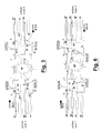
- a first unidirectional data flow (the data flow (a)) is inserted into the ring at the network element 1 (NE1) and allocated on the ⁇ WK #2; in NE2 there is a change of allocation from ⁇ WK #2 to ⁇ WK #1; in NE3 there is another allocation change from ⁇ WK #1 to ⁇ WK #8; finally, the data flow (a) is extracted from the ring at NE4.
- a second unidirectional data flow (the data flow (b)) is inserted into the ring at NE4 and allocated on the ⁇ WK #6; in NE3 there is a change of allocation from ⁇ WK #6 to ⁇ WK #3; in NE2 there is another change of allocation from ⁇ WK #3 to ⁇ WK #5; finally, the data flow (b) is extracted from the ring at NE1.
- the nodes do not detect any interchange request ("Idle" status).
- the nodes 2 and 3 become "switching" nodes.
- the switching nodes 2 and 3 issue, one to each other, appropriate signalings which will travel in the ring in opposite directions and will signal, by an appropriate code, at least the following information: Cause of request, Node of Destination, Source Node, Direction of Communication, Status of Protection.
- the Bridge & Switch action is implemented (ring switch near end) by the switching nodes 2 and 3, while the other nodes of the ring are in "Pass-Through” and implement the pass-through of ⁇ PR and of signaling generated by the switching nodes.
- the Bridge & Switch action represented by the ring switch near end is implemented by utilizing the protection wavelength corresponding to the working wavelength allocated in the span affected by a failure.
- the choice criterion of ⁇ PR to be utilized for the protection is that chosen to implement, in general, the ring switch near end process.
- the data flow (b), which in the span affected by SF is allocated on the ⁇ #3, shall be allocated on the ⁇ #11, always with the hypothesis of n 16.
- the implementation above described is fitted for single or two-fiber ring topology and constitutes a choice criterion example of protecting resource vis-à-vis the corresponding working resource to be protected: the criterion just described is applicable to whichever rule which binds the generic working resource allocated in the generic span of the ring to the corresponding protecting resource of the same span.
- a first unidirectional data flow (the data flow (a)) is inserted into the ring at NE1 and allocated on the ⁇ WK #2; in NE2 there is a change of allocation from ⁇ WK #2 to ⁇ WK #1; in NE3 there is another change of allocation from ⁇ WK #1 to ⁇ WK #8; finally, the data flow (a) is extracted from the ring at NE4.
- a second unidirectional data flow (the data flow (b)) is inserted into the ring at NE4 and allocated on the ⁇ WK #6; in NE3 there is a change of allocation from ⁇ WK #6 to ⁇ WK #3; in NE2 there is another change of allocation from ⁇ WK #3 to ⁇ WK #5; finally, the data flow (b) is extracted from the ring at NE1. All the nodes are in the Idle status.
- a failure (SF) of ring type happens in the span 2-3 of the ring.
- the nodes 2 and 3 become switching nodes.
- the switching nodes 2 and 3 will interchange appropriate signalings which travel in the ring in opposite directions, the signalings having the already described contents.
- the Bridge & Switch action is implemented (ring switch near end) by the switching nodes 2 and 3, while the other nodes of the ring are placed in the state of "pass-through” and implement the pass-through of ⁇ PR .
- ⁇ PR ⁇ WK # X, where X is the index of ⁇ WK in the span affected by a failure.
- a "generic" pictorial representation shall be utilized (valid both for two-fiber and four-fiber rings) of Fig. 7.
- the connections between nodes have been represented in a bidirectional manner.
- a single data flow (data flow (a)) installed.
- the data flow (a) is inserted in NE1 and allocated on the ⁇ #2; in NE2 a change of allocation from ⁇ #2 to ⁇ #1 occurs; in NE3 a change of allocation from ⁇ #1 to ⁇ #8 occurs; the data flow (a) is terminated in NE4. In a free-of-failure condition, all the nodes are in the idle status.
- a first failure SF1 occurs in the span 1-2: the nodes 1 and 2 become switching nodes.
- a second failure SF2 occurs in the span 2-3: also NE3 becomes a switching node.
- NE2 shall remain isolated from the ring.
- the switching nodes 1 and 3 will send corresponding signals towards NE2 with the respective interchange requests for SF1 and SF2: once that both of them have received an interchange request addressed to NE2, the isolation of NE2 is ascertained.
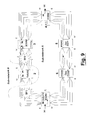
- the ring network becomes divided in two sub-networks (Fig. 8): a first sub-network (sub-network A) comprising all the nodes excepting the isolated node 2 and a second sub-network (sub-network B) comprising NE2.
- the switching nodes check if the termination nodes of the data flow which passes through the isolated node belong to the first or the second sub-network, that is if they are ableto communicate with them. This check is implemented by comparing the failure position with the configuration data bearing the information of the entire allocation of the data flow in WLI in the ring (the information is available in all the nodes involved in the allocation itself).
- the termination nodes of data flow (a), which passes through the isolated node 2 belong to the sub-network A: the data flow is to be protected by using, according to one of the criteria already mentioned, the ⁇ PR associated to ⁇ WK utilized for the allocation of the same data flow in one of the two spans affected by a failure.
- the switching nodes which have to implement the "Bridge & Switch" action are the nodes 1 and 3 which belong to the sub-network A.
- the switching node having the lower ID code is NE1; the span affected by a failure which is adjacent to the switching node with a lower ID code is therefore the span 1-2; the data flow (a), in the span 1-2 is allocated on the ⁇ WK #2.
- the occurrence of two failures (SF1 and SF2) in spans which are not adjacent to the same node results in the isolation of two nodes (3 and 2).
- the resulting sub-networks which are in this way defined are the Sub-network A, comprising the nodes 1, 4, 5 and 6, and the Sub-network B, comprising the nodes 2 and 3.
- the next step consists in identifying the position of termination nodes of each data flow and in checking that both the termination nodes of each data flow belong to one or to the other sub-network.
- both the termination nodes (1, 4) of the data flow (a) belong to the the sub-network A and both the termination nodes (2, 3) of the data flow (b) belong the to the sub-network B: both the data flows can be saved notwithstanding the two failures and the WLI in the nodes.
- the switching nodes are the nodes 1 and 5.
- the switching node with the lower ID is NE1. Therefore the span affected by a failure adjacent to the switching node with a lower ID is the span 1-3.
- the switching nodes are the nodes 2 and 3.
- the switching node with a lower identification is NE2.
- the span affected by a failure which is adjacent to the switching node with a lower ID is therefore the span 2-5.
- Fig. 13 illustrates a possible representation of the above said table, indicated by the name of "Permutation Table".
- the order and the arrangement of information contained in such a permutation table can of course vary from those indicated in the given representation.
- the table comprises 2M lines, wherein M is the number of ⁇ WK carried by the generic OMS-n line signal and the duplication refers to both the two possible allocation directions of the single unidirectional data flow in the ring.
- the first column, identified by "DATA FLOW #” indicates the number of the data flow and the direction (from W to E or from E to W).
- the next columns are relevant to each node of the ring (1 st NODE - 16 th NODE) to which the respective node identification (Node ID) is associated.
- the number of nodes to be managed by the protection mechanism is connected only with the bits (bytes) number assigned in the field of the signaling protocol on the base of the protection mechanism itself, for the communication of the identification code of node: the example mentioned concerns 16 nodes, since it is assumed that 4 bits of a 8-bit byte are dedicated for the signaling of the identification of the "Source Node” and of the "Destination Node".
- node For each node information are supplied; such information being related to the fact that a certain data flow, in that node, is Dropped (D), Inserted (I) or allowed to transit (PT), and being relevant to the ⁇ where the data flow is allocated (column ⁇ , figures from 1 to M) and relevant to possible wavelength concatenations (column Cl). These information are supplied for each node distinguishing between East and West sides.
- Each node involved in the allocation of the data flow in WLI if called to act as a "switching" node, having the possibility of look up such a table, is in a position of considering the identification of span affected by a failure, of defining some sub-networks, of identifying the data flow that could be recovered, of Surveyng the reference span, of identifying the reference ⁇ WK and of Selfng the corresponding ⁇ PR for the re-routing.
- any "ring switch” results in the preventive removal of the whole extra-traffic in the respective transmission nodes and the subsequent use of all the low priority channels for the protection operations of the traffic configured in the high priority channels.
- the ring network illustrated with the aim to describe the invention comprises ten network elements (NE) or nodes, indicated by rectangles and numbered by the respective numbers (from 1 to 10).
- flow (a) Two data flows, "flow (a)” and “flow (b)", are represented in the ring by way of a mere non limiting and exemplifying example.
- the first flow (flow a) has been represented by a continuous bold line while the second flow (flow b) has been represented by a bold dotted line.
- the flow (a) is inserted at the NE2 and is extracted at the NE8.
- the flow (b) is inserted at the NE4 and is extracted at the NE9.
- Fig. 14 shows a failure protected ring in an OMS-SPRING configuration where the Wavelength Interchange (WLI) occurs.
- Two are the data flows installed: (a) and (b).
- the flow (a) enters the ring at NE2 and is allocated on the ⁇ #1; therefore, in the span 2-3 the allocation is ⁇ #1; in NE3 the allocation is not changed; in NE4, the allocation is changed from ⁇ #1 to ⁇ #3; therefore, in the span 4-5 the allocation is ⁇ #3; in NE5, the allocation is not changed; in span 5-6 the allocation is therefore ⁇ #3; in the NE6, the allocation is changed from ⁇ #3 to ⁇ #7; in the span 6-7 the allocation is therefore ⁇ #7; in the NE7 the allocation changes again from ⁇ #7 to ⁇ #6; therefore, in the span 7-8 the allocation is ⁇ #6; the flow (a) is extracted at the NE8.
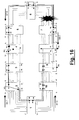
- the present invention provides a method for overcoming this failure notwithstanding the presence of wavelength allocation changes in the ring. It is necessary to refer, for the single ring failure, to the Fig. 15 and 16 wherein a ring failure in the span 6-7 has been simulated.
- the nodes which are adjacent to the failure (6 and 7) will transmit appropriate signals of failure in the opposite direction to the failure itself.
- the NE6 will transmit to NE7 a signal for indicating the occurrence of a ring failure in the span 6-7 and that no action has been now undertaken.
- This signaling shoud contain, at least, the following information: Cause of the Request (for instance Signal Failure), Destination Node (namely NE7), Source Node (namely NE6), Communication Direction ("long" path of the ring), Status of Protection (that is "no action status").
- NE7 operates in a similar way by issuing a congruent signaling towards the NE6 from its East (E) side: Cause of the Request (Signal Failure), Destination Node (that is the node “6"), Source Node (that is the node “7”), Communication Direction ("long” path of ring), Status of Protection ("no action status").
- BR&SW Bridge & Switch
- the ring protection in the case of a single ring type failure, is implemented by removing the terminations of the extra-traffic allocated on the ⁇ PR relating to the span affected by an event and by allocating the normal traffic on such ⁇ .
- the high priority traffic protection which requires the use of at least one of the protecting wavelengths utilized in the WLI at low priority, should bring nevertheless the action of removing of both the terminations of the low priority traffic.
- the BR&SW will be removed and the failure signalings eliminated.
- the present invention in addition to the case of the above illustrated single event, provides for a traffic protection method applicable to multiple failures resulting in the isolation of one or more nodes, wherein the WLI of the installed flow is configurated.
- three event scenarios are separately considered and described: in the first scenario the events occur in the same time, in the second scenario the events occur almost in the same time, while in the third scenario the events occur in different times.
- the BR&SW action on the ⁇ PR chosen with the same above criterion is implemented by each termination node of the Normal Traffic flow to be protected when both the signals with "bridge and switch" code are detected at both sides of the node itself.
- this node When the signalings containing the "no action" code of the first event reach the NE2 (Fig. 18.5) terminating the flow (a), this node will implement the BR&SW action by utilizing the ⁇ PR corresponding to the ⁇ WK of the span affected by the first event (in the specific case, ⁇ PR #7). Nevertheless, when the new signaling (generated by the NE8 towards the NE7) relevant to the second event (SF2) reachs the NE2, the just implemented BR&SW action is removed (Fig. 18.6).
- the actions preceding the temporary BR&SW just described are the removal of the local termination (whether present) of the Extra Traffic allocated on the ⁇ PR associated to the span 6-7 both on the termination nodes of the flow to be protected and on the nodes called to implement the pass-through of the wavelengths as well as the pass-through connection of the ⁇ PR themselves: for the implementation of such actions it is sufficient, at the node involved, the reception of at least one of the two signalings with "no action" code generated by the switching nodes.
- the NE8 when the signaling containing the "no action" code of the first failure reaches the NE8, the NE8 will issue a signaling containing the code of "bridge and switch status" (Fig. 18.9). The same will occur for the NE6: upon receipt the signaling containing the "no action” code of the first event, it will send a signaling containing the code of "bridge and switch status" (Fig. 18.10).
- the NE6 Owing to the presence of the new signaling (generated by NE8 towards the NE7 with “no action status” code) relevant to the second event (SF2), the NE6 will change again its signaling passing from code of "bridge and switch status” to the code of "no action status” (Fig. 18.11).
- the NE9 upon receiving from both its W and E sides a signaling with the "bridge and switch” code relating to the two detected events, will implement the BR&SW action by utilizing the allocation of the "protecting" wavelength relating to one of the spans that are affected by the event, for example the span affected by the first event ( ⁇ PR #6).
- the NE4 upon receiving signalings with a BR&SW code from both the sides, will implement the BR&SW action by utilizing the ⁇ PR relating to one of the spans affected by event, for example the span affected by the first event ( ⁇ PR #6).
- the NE2 upon receiving from both its W and E sides a signaling with a BR&SW code (generated by nodes 6 and 8), will implement the BR&SW action (Fig. 18.16) by utilizing the allocation of protecting wavelength relevant to one of the span affected by event, for example the span affected by the first event ( ⁇ PR #7).
- the first event (SF1) has occurred.
- the NE6 sends a failure signal towards the NE7 from the W side, containing the "no action" code.
- the NE7 sends from the E side an equivalent signal towards the NE6 (Fig. 15).
- Both the so generated signalings reach the termination nodes of the flows (a) and (b).
- the termination nodes implement the BR&SW action for each flow to be protected by utilizing the corresponding protecting wavelengths of the span affected by SF1.
- the flow (a) is allocated on the ⁇ PR #7.
- the flow (b) is allocated on the ⁇ PR #6 (Fig. 3).
- the nodes 6 and 7 adjacent to the event/failure SF1 send, each to each other, the respective signalings with a "bridge and switch" code and there is a stable scenario of ring protected against SF1 (Fig. 3).
- SF2 occurs in the span 7-8: the NE7 is isolated (Fig. 19.1).
- the NE8 issues from the E side an appropriate signaling towards the NE7 with a "no action" code (Fig. 19.2).
- the NE6 receives the signaling generated by the NE8 for the NE7 and issues an equivalent signaling for the NE7 (Fig. 19.7).
- the NE8 receives the signaling just generated by the NE6 and updates its own transmission by reporting the code of BR&SW status (Fig. 19.8).
- the NE6 receives the signaling generated by the NE8 with "bridge and switch” code and on its turn updates its own signaling with the BR&SW code (Fig. 19.9).
- the nodes 2 and 8 receive the signalings generated by the nodes 8 and 6 towards the NE7 (isolated) containing the "bridge and switch" code and implement the BR&SW action by utilizing, for example, the ⁇ PR corresponding to the one of the first failed span ( ⁇ PR #7).
- the scenario becomes stable for the flow (a) ( Figures 19.10, 19.11).
- the nodes 4 and 9 receive the signalings generated by the nodes 8 and 6 towards the NE7 (isolated) containing the "bridge and switch" code and implement the BR&SW action by utilizing for example the ⁇ PR corresponding to the one of the first failed span ( ⁇ PR #6).
- the scenario becomes stable for the flow (b) ( Figures 19.12, 19.13).
- the first failure occurs (SF1).
- the NE6 sends a signaling with "no action” code from the W side towards the NE7.
- the NE7 sends an equivalent signaling from the E side towards the NE6 (Fig. 14).
- Both the signalings reach the termination nodes of flows (a) and (b).
- the termination nodes implement the BR&SW action for each flow to be protected by utilizing the corresponding ⁇ PR of the span affected by SF1.
- the flow (a) is allocated on the ⁇ PR #7.
- the flow (b) is allocated on the ⁇ PR #6 (Fig. 15).
- the nodes 6 and 7 adjacent to the failure SF1 receive the signalings with "no action” code and send, one to each other, the respective signalings with a “bridge and switch” code and so there is a stable scenario of ring protected against SF1 (Fig. 16).
- SF2 occurs in the span 7-8: the NE7 becomes isolated (Fig. 20.1).
- the NE8 sends from the E side towards the NE7 an appropriate signaling with a "no action" code (Fig. 20.2).
- the NE8 in its capacity of node adjacent to the failure and termination node, evaluates if the already protected flows can be protected. In a positive case no action is undertaken, in a negative case the BR&SW action is removed (Fig. 20.3).
- the NE9 receives the request generated by the NE8 for the NE7 and evaluates if the already protected flows can be still protected. In the affirmative, no action is undertaken; in the negative, the BR&SW action is removed (Fig. 20.4).
- the NE2 receives the request generated by the NE8 for the NE7 and evaluates if the already protected flows can be still protected. In the affirmative case, no action is undertaken; in the negative case, the BR&SW action is removed (Fig. 20.5).
- the NE4 receives the request generated by the NE8 for the NE7 and evaluates if the already protected flows can be still protected. In the affirmative, no action is undertaken; in the negative, the BR&SW action is removed (Fig. 20.6).
- the NE6 When the NE6 receives the signaling generated by the NE8 for the NE7, it updates its request (towards the NE7) by inserting a code equal to "no action".
- the nodes adjacent to the failure update the respective signalings by inserting the selector status code equal to "bridge and switch".
- the first sub-scenario involves a relatively simple implementation, since it is not necessary to store the "history" of the events, but in the same time the traffic is not saved in an optimal manner as the BR&SW action is always removed.
- the second sub-scenario saves the traffic in a better way, but it is more difficult to implement, as the "history" of traffic has to be stored.
- the BR&SW action (and removal of the possible local terminations of Extra Traffic allocated on the ⁇ PR utilized) in the NE4 has to be removed.
- the signaling generated by the NE7 reaches the other flow termination nodes (2, 9, 8)
- the BR&SW action and the possible "removal of the local "Extra Traffic” are removed also in these nodes 2, 9, 8 ( Figures 21.3-21.5).
- the removal of "BR&SW” in the termination nodes is accompanied by the removal of the pass-through (and of the possible removal of the local Extra Traffic) by the intermediate nodes which have implemented the pass-through of the "protecting" wavelength which was so far utilized for the protection.
- the signalings present in the intermediate nodes refer to the same span affected by a failure, these nodes can implement, where requested, the pass-through of the ⁇ PR , relating to the current failure, to be utilized for the protection of the flows.
- the NE8 in its capacity of node adjacent to the failure SF2, receives the signaling generated by the NE7 with a "no action” code and changes the code of its signaling for the NE7 from BR&SW code to "no action” code (Fig. 21.6). Such signaling with "no action” code reaches all the termination nodes (9, 2, 4) and in such a way indicates to them that a single failure (SF2) is present.
- the termination nodes shall implement the BR&SW action ( Figures 21.8-21.10) by utilizing the ⁇ PR which correspond to the span affected by a failure/event (for the flow (a), the ⁇ PR #6 will be used, for the flow (b), the ⁇ PR #7 will be used).
- the nodes (7, 8) adjacent to the still present event (SF2) will send, one towards the other, corresponding signalings with a "bridge and switch” code and a stable condition of single event will be reached ( Figures 21.11-21.12).
- the BR&SW action in the NE8 can be maintained (Fig. 22.3). Similarly, the signaling generated by the NE7 for the NE6, reaches the other flow termination nodes (9, 2, 4), but the BR&SW action is kept also in these nodes 9, 2, 4 ( Figures 22.4-22.6).
- the NE6 adjacent to the event SF1 receives the signaling generated by the NE7 and will send the corresponding signaling with the selector status code equal to "no action" thus coming to a stable scenario with signalings of "bridge and switch” code in the whole ring.
- the ring When also SF1 is removed, the ring shall reach the stable condition without failures, with the progressive removal of the "Bridge” and "Switch” actions by all the flow termination nodes and the subsequent signalings with a code indicating the absence of requests by all the ring nodes, including the nodes (6, 7) adjacent to the just removed event (SF2). See Figures 22.7 and 22.8.
Landscapes
- Engineering & Computer Science (AREA)
- Computer Networks & Wireless Communication (AREA)
- Signal Processing (AREA)
- Small-Scale Networks (AREA)
- Optical Communication System (AREA)
Abstract
Description
- "bridge", namely an action by which the data flow inserted in the generic working wavelength is inserted into the corresponding protecting wavelength through the contemporary insertion into both the wavelengths or through the selection of the only protecting wavelength.
- "switch", namely an action by which the data flow is selected no more by the working wavelength, but by the corresponding protecting wavelength.
- "span switch": a protection process which is operated due to interchange reasons (failures or commands) detected at Optical Multiplex Section level in the fiber span which connects two of the nodes of the ring network under examination, and which causes the loss of only the high priority traffic carried on that span, that is makes the only working resource associated to that span unavailable. The span switch consists in the "bridge & switch" (BR&SW) action implemented in the nodes at the ends of the span affected by interchange cause, by exploiting the protecting resource which is available in the span itself.
- "ring switch near end": a protection process which is operated due to interchange reasons (failures or commands) detected at Optical Multiplex Section level in the span which connects two of the nodes of the ring network under examination, and which causes the loss both of NT traffic and of ET traffic carried on that span, that is makes both the working and protecting resources associated to that span unavailable. The ring switch near end consists in the BR&SW action implemented in the nodes at the ends of the span affected by interchange cause, by exploiting the alternative path of the ring network which connects the two nodes implementing the action.
- "ring switch far end": protection process which is operated due to interchange reasons (failures or commands) detected at Optical Multiplex Section level in the span connecting two of the nodes of the ring network under examination, and which causes the loss of both the NT traffic and the ET traffic carried onto that span, that is makes both the working and protecting resources associated to that span unavailable. The ring switch far end consists in the BR&SW action implemented in the termination nodes (add/drop) of high priority traffic carried in the span affected by the interchange cause, by exploiting the alternative path of the ring network which connects the two nodes implementing the action.
- "Reason of the request " indicates by an appropriate code - depending on a possible priority logic of the events - the type of failure;
- "Source Node " indicates, by an appropriate code the ID of the node which generates the signaling;
- "Destination Node" indicates, by an appropriate code, the ID of the node to which the signaling generated by the "Source Node" is addressed;
- "Direction of Communication" indicates, by an appropriate code, the path which the signaling generated by the generic node is following to reach the adjacent node. It is possible to distinguish a "short" path, if the communication between both the nodes occurs directly through the connection span between them, from a "long" path when the communication between both the generic nodes can not occur through the connection span (because of failures) and therefore utilizes the remaining spans of the same ring;
- "Status of protection" indicates, by an appropriate code, the re-configuration
state of connection matrices, by distinguishing in principle among
the following conditions:
- No action, after the identification of an interchange cause and the beginning or modification of a protection process, namely, in general, when neither the "Bridge", nor the "Switch" actions are in progress (that is no modification of the re-connection matrices).
- Bridge and Switch, after the reciprocal reception, by the switching nodes, of the signaling containing the "Status of protection" which indicates "no action".
- Fig. 1 shows a two-fiber ring network with a plurality of nodes, two data flows installed on different wavelengths along the ring, in a stable situation free of failures;
- Fig. 2 shows the same ring network of Fig. 1 immediately after a ring failure has occurred;
- Fig. 3 shows the Bridge & Switch near end action implemented at the nodes which could be defined as those adjacent to the span affected by a "switching" failure of the ring network of Fig. 2;
- Fig. 4 shows a four-fiber ring network with a plurality of nodes, two data flows installed on different wavelengths along the ring in a stable situation free of failures;
- Fig. 5 shows the same ring network as per Fig. 4 immediately after a ring type failure;
- Fig. 6 shows the Bridge & Switch action implemented at the nodes which could be defined as "switching" nodes of the ring network of Fig. 5;
- Fig. 7 shows a two/four-fiber ring network with a plurality of nodes, a single data flow installed on different wavelengths along the ring in a stable situation free of failures;
- Fig. 8 shows the network of Fig. 7 in case of double failure causing an isolation of a node and the identification of two sub-networks;
- Fig. 9 shows a possible criterion by which it is possible to protect the data flow as per Fig. 8;
- Fig. 10 shows a two/four-fiber ring network with a plurality of nodes, two data flows installed on different wavelengths along with the ring in a stable situation free of failures;
- Fig. 11 shows the network of Fig. 10 in case of double failure with consequent isolation of two nodes and the definition of two sub-networks;
- Fig 12 shows a possible criterion by which it is possible to protect the data flow of Fig. 11;
- Fig. 13 shows a possible representation of permutation table;
- Fig. 14 shows a ring network with a plurality of nodes, two data flows installed and some allocation changes in a stable situation free of failures;
- Fig. 15 shows the same ring network as per Fig. 14 immediately after a ring type failure;
- Fig. 16 shows the ring network as per Fig. 15 in a stable situation with a ring type failure;
- Figs. 17 show the signals received/generated by single nodes and the relevant actions undertaken in case of double contemporary failure (two failures at the same time);
- Figs. 18 show the signals received/generated by single nodes and the corresponding actions undertaken in the case of double almost contemporary failure;
- Figs. 19 show the signals received/generated by single nodes and the corresponding actions undertaken in the case of double failures in different times (first subscenario);
- Figs. 20 show the signals received/generated by single nodes and the corresponding actions undertaken in the case of double failure in different times (second subscenario);
- Figs. 21 show the signals received/generated by single nodes and the corresponding actions undertaken in case of restoring of a first failure; and
- Figs. 22 show the signals received/generated by single nodes and the relevant actions undertaken in case of elimination of a second failure.
- by the switching nodes, in case of "near end ring switch"
- by the termination nodes (nodes wherein the data flow to be protected is inserted into the ring or extracted from the ring) of the data flow allocated in the λWK , in the case of a far end ring switch.
Claims (16)
- Method for managing the traffic protection in an Optical Multiplex Section-Shared Protection Ring network in case of failure (SF1) to a span of an installed path, said network comprising network elements connected one to each other through fiber spans in a ring configuration, said fiber spans comprising working wavelengths for transporting high priority traffic and protecting wavelengths for transporting low priority traffic, said method being characterized in that it comprises the steps of:providing a wavelength interchange mechanism (WLI)implementing a ring Span Switch action by an Optical Multiplex Section-Shared Protection (OMS-SP) mechanism,re-routing the wavelength interchanged (WLI) path on the protecting wavelength corresponding to the working wavelength of span affected by a failure.
- Method according to claim 1, wherein a further span is affected by a failure (SF2) and a protection process of ring switch near end type is provided, the method being characterized by the step of selecting one between the two spans affected by a failure thus providing a selected failured span and by the step of re-routing the wavelength interchanged (WLI) path on the protecting wavelength corresponding to the working wavelength of the selected failured span.
- Method according to claim 1 or 2, wherein said Optical Multiplex Section-Shared Protection Ring network is a two-fiber network, the method being characterized in that the step of re-routing the wavelength interchanged (WLI) path on the protecting wavelength comprises the step of re-routing the path on the protecting wavelengh having an index given by the sum of half overall number of the handled channels (n) and the index of the working wavelength allocated on the failured span or on the selected failured span.
- Method according to claims 1 or 2, wherein said Optical Multiplex Section-Shared Protection Ring network is a four-fiber network, the method being characterized in that the step of re-routing the wavelength interchanged (WLI) path on the protecting wavelength comprises the step of re-routing the path on the protecting wavelength having an index corresponding to the working wavelength of the channel allocated on the failured span or on the selected failured span.
- Method according to any of claims 2 to 4, characterized in that the step of selecting one of the two failured spans comprises the step of selecting the failured span adjacent to the switching node with higher/lower node ID.
- Method according to any of claims 2 to 4, characterized in that the step of selecting one of the two failured spans comprises the step of selecting the failured span adjacent to the switching node that comes first/last in the ring network map.
- Method according to any of claims 2 to 4, characterized in that the step of selecting one of the two failured spans comprises the step of selecting the failured span adjacent to the switching node which is placed far East/West in the ring network.
- Method according to any of claims 2 to 7, characterized by comprising the additional steps of subdividing the ring network into two sub-networks (A, B), a sub-network (B) comprising the at least one node that has become isolated by the failures (SF1, SF2), the other sub-network (A) comprising the other nodes of the ring network, and checking whether the path can be re-routed by evaluating if both the corresponding termination nodes belong to one or to the other sub-network (A, B).
- Method according to claim 1, in which a further span of the path is affected by a failure and a protection process of "ring switch far end" type is provided, the method being characterized by comprising the steps of: i) releasing the present re-routing which was implemented for the first failured span; ii) selecting one of the failured spans; e iii) re-routing the path on the protecting wavelength corresponding to the working wavelength of the selected failured span.
- Method according to claim 1, wherein a further span of path becomes affected by a failure and a protection process of "ring switch far end" type is provided, characterized by comprising the step of keeping the present re-routing, implemented for the first failured span, whether the persistency of the re-routing information is supported by ring network elements.
- Method according to any of the preceding claims, characterized by comprising the further step of providing all the network elements involved in the allocation of the wavelength interchanged (WLI) path with information concerning the whole allocation of the path into the ring, namely at which node the WLI path is Dropped (D), Inserted (I) or allowed to transit (PT), on which wavelength the path involved is allocated (1,... n) and relating to possible present concatenations (Cl), by distinguishing between East (E) and West (W) sides.
- Network element of an OMS-SPRING ring network, said ring network comprising further network elements connected one to each other in a ring configuration through fiber spans, said fiber spans comprising working wavelengths for transporting high priority traffic and protecting wavelengths for transporting low priority traffic, said network element comprising means for implementing ring switch actions, namely pass-through, bridge or switch actions, upon receiving corresponding signalings and means for generating and sending proper signalings in reply to the corresponding signalings in said ring network, wherein a path is installed, characterized in that in said ring network an interchange wavelength mechanism (WLI) is provided and in that said network element, should a failure occurr in a span of the installed path, comprises means for re-routing the path on the protecting wavelength corresponding to the working wavelength of the failured span.
- Network element according to claim 12, wherein a further span of the path becomes failured, characterized by comprising: means for selecting one of the two failured spans and means for re-routing the path on the time-slot of the low priority channels (LP) corresponding to the working wavelength of the selected failured span.
- Network element according to any of claims 12 to 13 in which said OMS-SPRING ring network is a two-fiber network, the network element being characterized in that the means for re-routing the path on the protecting wavelength comprise means for re-routing the path on the wavelength having an index given by the sum of the half overall number of wavelengths (n) and the index of the working wavelength allocated on the failured span or on the selected failured span.
- Network element according to any of claims 12 to 13 in which said OMS-SPRING ring network is a four-fiber network, the network element being characterized in that the means for re-routing the path on the protecting wavelength comprise means for re-routing the path on the protecting wavelength having an index corresponding to the working wavelength allocated on the failured span or on the selected failured span.
- Network element according to any of claims 12 to 15, wherein a further span of the path becomes failured, characterized by comprising means for keeping the present re-routing, implemented for the first failured span, if the persistency of re-routing information is supported by the ring network elements.
Applications Claiming Priority (2)
| Application Number | Priority Date | Filing Date | Title |
|---|---|---|---|
| IT2001MI001139A ITMI20011139A1 (en) | 2001-05-30 | 2001-05-30 | METHOD FOR MANAGING TRAFFIC PROTECTION IN OMS-SPRING RING NETWORKS |
| ITMI20011139 | 2001-05-30 |
Publications (2)
| Publication Number | Publication Date |
|---|---|
| EP1263259A2 true EP1263259A2 (en) | 2002-12-04 |
| EP1263259A3 EP1263259A3 (en) | 2009-03-18 |
Family
ID=11447774
Family Applications (1)
| Application Number | Title | Priority Date | Filing Date |
|---|---|---|---|
| EP02291179A Withdrawn EP1263259A3 (en) | 2001-05-30 | 2002-05-13 | Method of managing the traffic protection in OMS-SPRING ring networks |
Country Status (3)
| Country | Link |
|---|---|
| US (1) | US7224895B2 (en) |
| EP (1) | EP1263259A3 (en) |
| IT (1) | ITMI20011139A1 (en) |
Families Citing this family (6)
| Publication number | Priority date | Publication date | Assignee | Title |
|---|---|---|---|---|
| JP3957065B2 (en) * | 2002-08-28 | 2007-08-08 | 富士通株式会社 | Network computer system and management device |
| US8909038B2 (en) * | 2003-01-07 | 2014-12-09 | Alcatel Lucent | Method and apparatus providing transient control in optical add-drop nodes |
| US7826345B2 (en) * | 2003-07-08 | 2010-11-02 | Sycamore Networks, Inc. | Network span protection using span identifiers |
| WO2015006568A1 (en) * | 2013-07-11 | 2015-01-15 | Plexxi Inc. | Network node connection configuration |
| CN105515808B (en) * | 2014-09-26 | 2019-11-05 | 中兴通讯股份有限公司 | A kind of pair of multiplex section ring switch the method and electronic equipment of manoeuvre |
| US10972309B2 (en) * | 2017-04-20 | 2021-04-06 | Sino-Telecom Technology Co., Inc. | Method and device for automatically discovering cross-node service topology on transoceanic multiple section shared protection ring |
Family Cites Families (12)
| Publication number | Priority date | Publication date | Assignee | Title |
|---|---|---|---|---|
| JP2578704B2 (en) * | 1991-03-26 | 1997-02-05 | 日本電信電話株式会社 | Ring transmission network loopback method and ring transmission apparatus |
| GB9210521D0 (en) * | 1992-05-16 | 1992-07-01 | Cadcam Punch Ltd | Cutting and embroidery process |
| IT1267645B1 (en) * | 1994-12-09 | 1997-02-07 | Cselt Centro Studi Lab Telecom | RING COMMUNICATION STRUCTURE ON OPTICAL VECTOR AND RELATIVE RECONFIGURABLE NODE. |
| US5815490A (en) * | 1995-11-20 | 1998-09-29 | Nec America, Inc. | SDH ring high order path management |
| US5745476A (en) * | 1996-07-16 | 1998-04-28 | At&T Corp. | Errorless switching techniques in ring network |
| US6728205B1 (en) * | 1997-02-19 | 2004-04-27 | Massachusetts Institute Of Technology | Method and apparatus for automatic protection switching |
| US6657952B1 (en) * | 1997-11-28 | 2003-12-02 | Nec Corporation | Ring network for sharing protection resource by working communication paths |
| US6567194B1 (en) * | 1998-08-17 | 2003-05-20 | Corvis Corporation | Optical communication network and protection methods |
| IT1312225B1 (en) * | 1999-03-23 | 2002-04-09 | Cit Alcatel | OPTOELECTRIC NETWORK ELEMENT OPTIMIZED FOR CONVEYOR NETWORKS. |
| US6798747B1 (en) * | 1999-12-22 | 2004-09-28 | Worldcom, Inc. | System and method for time slot assignment in a fiber optic network simulation plan |
| US6795394B1 (en) * | 2000-04-26 | 2004-09-21 | Nortel Networks Limited | Data network having enhanced availability of extra traffic |
| EP1161014A1 (en) * | 2000-05-31 | 2001-12-05 | PIRELLI CAVI E SISTEMI S.p.A. | Autoprotected optical communication ring network |
-
2001
- 2001-05-30 IT IT2001MI001139A patent/ITMI20011139A1/en unknown
-
2002
- 2002-05-13 EP EP02291179A patent/EP1263259A3/en not_active Withdrawn
- 2002-05-17 US US10/146,812 patent/US7224895B2/en not_active Expired - Fee Related
Also Published As
| Publication number | Publication date |
|---|---|
| US20020181039A1 (en) | 2002-12-05 |
| ITMI20011139A1 (en) | 2002-11-30 |
| US7224895B2 (en) | 2007-05-29 |
| EP1263259A3 (en) | 2009-03-18 |
| ITMI20011139A0 (en) | 2001-05-30 |
Similar Documents
| Publication | Publication Date | Title |
|---|---|---|
| EP0969619B1 (en) | Survivable optical network | |
| JP3705222B2 (en) | Path setting method, communication network using the same, and node device | |
| US7046619B2 (en) | Method and system for bi-directional path switched network | |
| US6507561B1 (en) | Telecommunications network distributed restoration method and system | |
| CN1820438B (en) | Method for providing connection protection to additional traffic paths in a communication network, related network | |
| CN1754352B (en) | Device and method for fault relief of a channel in a communication network | |
| US7082137B2 (en) | Method of managing time-slot interchange in transoceanic MS-SPRING networks | |
| US20030065811A1 (en) | Methods and apparatus for allocating working and protection bandwidth in a network | |
| US6496476B1 (en) | System and method for restricted reuse of intact portions of failed paths | |
| JP3744362B2 (en) | Ring formation method and failure recovery method in network, and node address assignment method during ring formation | |
| US20070014573A1 (en) | Exchange structure and a method of connection configuration between the optical networks | |
| JPH11508421A (en) | Path setting based on information and allocation of spare capacity for distributed recovery of network | |
| CN1981463B (en) | Business connection set-up and business recovering protection method in optical network | |
| Li et al. | Fiber span failure protection in mesh optical networks | |
| US7224895B2 (en) | Method of managing the traffic protection in OMS-SPRING networks | |
| CN1780190B (en) | A method for processing optical network services | |
| US20020167899A1 (en) | System and method for the configuration, repair and protection of virtual ring networks | |
| EP1185014A2 (en) | Method of managing time slot interchange in classic MS-Spring networks | |
| US7355967B2 (en) | Transmission device | |
| EP2088695B1 (en) | Method for numbering working traffic on path protection ring | |
| EP1453233B1 (en) | Method and apparatus for dynamic provisioning of reliable connections in the presence of multiple failures | |
| EP1282249A2 (en) | Method of managing different type multiple failures in ring topology telecommunication networks | |
| JP2006060850A (en) | Path setup method, communication network, and central control system and node unit used for them | |
| WO2000016113A1 (en) | System and method for restricted reuse of intact portions of failed paths in a telecommunications network | |
| Zang | Connection Management for Survivable Wavelength-Routed Networks |
Legal Events
| Date | Code | Title | Description |
|---|---|---|---|
| PUAI | Public reference made under article 153(3) epc to a published international application that has entered the european phase |
Free format text: ORIGINAL CODE: 0009012 |
|
| AK | Designated contracting states |
Kind code of ref document: A2 Designated state(s): AT BE CH CY DE DK ES FI FR GB GR IE IT LI LU MC NL PT SE TR |
|
| AX | Request for extension of the european patent |
Free format text: AL;LT;LV;MK;RO;SI |
|
| RAP1 | Party data changed (applicant data changed or rights of an application transferred) |
Owner name: ALCATEL LUCENT |
|
| PUAL | Search report despatched |
Free format text: ORIGINAL CODE: 0009013 |
|
| AK | Designated contracting states |
Kind code of ref document: A3 Designated state(s): AT BE CH CY DE DK ES FI FR GB GR IE IT LI LU MC NL PT SE TR |
|
| AX | Request for extension of the european patent |
Extension state: AL LT LV MK RO SI |
|
| STAA | Information on the status of an ep patent application or granted ep patent |
Free format text: STATUS: THE APPLICATION HAS BEEN WITHDRAWN |
|
| 18W | Application withdrawn |
Effective date: 20090911 |