EP1263223A2 - Projector device - Google Patents
Projector device Download PDFInfo
- Publication number
- EP1263223A2 EP1263223A2 EP02011846A EP02011846A EP1263223A2 EP 1263223 A2 EP1263223 A2 EP 1263223A2 EP 02011846 A EP02011846 A EP 02011846A EP 02011846 A EP02011846 A EP 02011846A EP 1263223 A2 EP1263223 A2 EP 1263223A2
- Authority
- EP
- European Patent Office
- Prior art keywords
- optical system
- illuminating
- dmd
- digital micromirror
- projector device
- Prior art date
- Legal status (The legal status is an assumption and is not a legal conclusion. Google has not performed a legal analysis and makes no representation as to the accuracy of the status listed.)
- Granted
Links
Images




Classifications
-
- H—ELECTRICITY
- H04—ELECTRIC COMMUNICATION TECHNIQUE
- H04N—PICTORIAL COMMUNICATION, e.g. TELEVISION
- H04N9/00—Details of colour television systems
- H04N9/12—Picture reproducers
- H04N9/31—Projection devices for colour picture display, e.g. using electronic spatial light modulators [ESLM]
- H04N9/3141—Constructional details thereof
-
- H—ELECTRICITY
- H04—ELECTRIC COMMUNICATION TECHNIQUE
- H04N—PICTORIAL COMMUNICATION, e.g. TELEVISION
- H04N5/00—Details of television systems
- H04N5/74—Projection arrangements for image reproduction, e.g. using eidophor
- H04N5/7416—Projection arrangements for image reproduction, e.g. using eidophor involving the use of a spatial light modulator, e.g. a light valve, controlled by a video signal
- H04N5/7458—Projection arrangements for image reproduction, e.g. using eidophor involving the use of a spatial light modulator, e.g. a light valve, controlled by a video signal the modulator being an array of deformable mirrors, e.g. digital micromirror device [DMD]
-
- H—ELECTRICITY
- H04—ELECTRIC COMMUNICATION TECHNIQUE
- H04N—PICTORIAL COMMUNICATION, e.g. TELEVISION
- H04N9/00—Details of colour television systems
- H04N9/12—Picture reproducers
- H04N9/31—Projection devices for colour picture display, e.g. using electronic spatial light modulators [ESLM]
- H04N9/3102—Projection devices for colour picture display, e.g. using electronic spatial light modulators [ESLM] using two-dimensional electronic spatial light modulators
Definitions
- the present invention relates to a projector device, and more particularly to a projector device for projecting images on a screen by using a digital micromirror device (DMD).
- DMD digital micromirror device
- a DMD comprises a large number of micromirrors arranged in a matrix, in which each micromirror constitutes one pixel of a displayed image.
- Each micromirror can take one of two inclined states, an ON state and an OFF state. In the ON state, illuminating light is reflected into a projecting optical system, while in the OFF state it is projected away from the projecting optical system. Therefore, in a projector device using a DMD, the projecting optical system projects only the light reflected by micromirrors in the ON state, resulting in the formation of a displayed image composed of a pattern of different levels of brightness on the screen.
- Known projector devices using such a DMD include ones disclosed in Japanese Patent Application Publication Nos. 9-98442 and 12-206452.
- Fig. 7 shows a plan of a micromirror drive structure in a DMD
- Fig. 8 shows the 8-8 section in Fig. 7.
- the drawings show expanded views of one extracted out of many micromirrors constituting the DMD, which actually is configured of a large number of micromirrors arranged in a matrix.
- a micromirror 2 of a DMD 1 can take either an ON state inclined by +10° or an OFF state inclined by -10° to the DMD surface by turning around a rotation axis ab.
- This rotation axis ab of the micromirror 2 is set in a direction inclined by 45° to the long or short side of the DMD 1, and illuminating light L o irradiates the surface of the DMD 1 at an incidence angle of 20° in a direction orthogonal to this rotation axis ab.
- the illuminating light L o irradiating the DMD if reflected by the micromirror 2 in the ON state, turns into a projecting light L 1 whose angle of reflection by the surface of the DMD 1 is 0° or, if reflected by the micromirror 2 in the OFF state, turns into projecting light L 2 whose angle of reflection by the surface of the DMD 1 is -40°.
- Only the projecting light L 1 which is a luminous flux reflected by the micromirror 2 in the ON state at 0° in the angle of reflection, comes incident on the projecting optical system, and a displayed image composed of a pattern of different levels of brightness is formed on the screen.
- the illuminating optical system has to be configured to meet two constraints that the illuminating light L o should be brought to incidence in a direction orthogonal to the rotation axis of the micromirror 2 (a direction inclined by 45° to the long or short side of the DMD) and the illuminating light L o should further be brought to incidence at an angle of 20° to the surface of the DMD 1.
- a total internal reflection prism (TIR prism) is used to irradiate the DMD with illuminating light from a light source.
- TIR prism total internal reflection prism
- light emitted from a light source 3 is condensed into a rod integrator 4, guided by a first mirror 5 and a second mirror 6 to a TIR prism 7 and totally reflected by that TIR prism 7 thereby to irradiate the DMD 1 in a required direction (a direction inclined by 45° to the long or short side of the DMD 1) and at a predetermined incidence angle (20°).
- optical modulation is performed, and the light transmitted by the TIR prism 7 after that optical modulation is projected by a projecting optical system 8 onto a screen.
- this projector device since the illuminating light should be brought to incidence on the DMD 1 in an oblique direction as shown in Fig. 10 to meet the two constraints stated above and fixed in that state, involves the disadvantage of permitting no reduction in its overall thickness.
- An object of the present invention attempted in view of this circumstance, is to provide a projector device that permits a reduction in thickness.
- the present invention is directed to a projector device in which illuminating light from a light source is guided by an illuminating optical system to a digital micromirror device and irradiates the digital micromirror device at a predetermined incidence angle and in a predetermined direction, and light modulated by the digital micromirror device is projected by a projecting optical system on a screen, wherein: the direction of irradiation of the digital micromirror device with the illuminating light by the illuminating optical system is made variable depending on whether the projector device is used or unused.
- the irradiating direction of the DMD with the illuminating light by the illuminating optical system can be varied depending on whether the device is used or not used. Therefore, by irradiating the DMD with the illuminating light in the predetermined direction only when the projector device is used, the overall thickness of the device can be reduced when it is not used.
- the present invention is also directed to a projector device in which illuminating light from a light source is guided by an illuminating optical system to a digital micromirror device and irradiates the digital micromirror device at a predetermined incidence angle and in a predetermined direction, and light modulated by the digital micromirror device is projected by a projecting optical system on a screen, wherein: the digital micromirror device is provided rotatably around a rotation axis vertical to the digital micromirror device, at least part of the illuminating optical system is provided rotatably around the rotation axis so as not to let the direction of irradiation of the digital micromirror device from the illuminating optical system vary, and when the projector device is in use the inclination of the image projected on the screen is corrected by rotating at least part of the illuminating optical system and the digital micromirror device around the rotation axis.
- the DMD is provided rotatably around a rotation axis vertical to the DMD and at least part of the illuminating optical system is provided rotatably around the rotation axis so as not to let the direction of irradiation of the DMD from the illuminating optical system vary.
- the inclination of the image projected on the screen is corrected by rotating at least part of the illuminating optical system and the DMD around the rotation axis. This makes it possible to configure a projector device reduced in thickness when it is not in use.
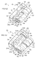
- Figs. 1(a) and 1(b) are perspective views showing the schematic configuration of a projector device, which is a first preferred embodiment of the invention.
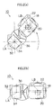
- Figs. 2(a) and 2(b) are front views
- Figs. 3(a) and 3(b) are plan views
- Figs. 4(a) and 4(b) profile views respectively showing the schematic configuration of its optical system.
- Figs. 2(a), 3(a) and 4(a) illustrate a state in which the projector device is used
- Figs. 2(b), 3(b) and 4(b) illustrate a state in which it is not used.
- a projector device 10 As shown in Figs. 1(a) through 4(b), a projector device 10 according to an embodiment of the present invention comprises a fixed frame 12, a rotating frame 14, an illuminating optical system 16, a TIR prism 18, a DMD 20 and a projecting optical system 22.
- the fixed frame 12 is fixed to the main frame of the projector device (not shown) with bolts or the like, and the rotating frame 14 is supported to be rotatable around an optical axis LA (the optical axis of the illuminating optical system) relative to this fixed frame 12.
- the rotating frame 14 is rotatably supported around the optical axis LA relative to the fixed frame 12 as a shaft part 24A formed on one of its end faces is borne by a bearing part 26A formed on the fixed frame 12 and an annual shaft part 24B formed on the other end face is borne by an annual bearing part 26B formed on the fixed frame 12.
- This rotating frame 14 by rotating around the optical axis LA, takes either one of two states including a state of non-use, in which it is horizontal relative to the fixed frame 12 state (the state of Fig. 1(b)) and a state of use in which it is inclined by 45° to the fixed frame 12 (the state of Fig. 1(a)).
- a state of non-use in which it is horizontal relative to the fixed frame 12 state (the state of Fig. 1(b))
- a state of use in which it is inclined by 45° to the fixed frame 12 (the state of Fig. 1(a)).
- the rotating frame 14 In the state of use, the rotating frame 14 is fixed to the fixed frame 12 by a stopper (not shown), and its inclined state is thereby maintained.
- the illuminating optical system 16 comprising a light source 28, a rod integrator 30, a relay lens 32, a reflecting mirror 34 and a color wheel 36, guides the illuminating light emitted from the light source 28 to the TIR prism 18.
- the light source 28, comprising a light source lamp and a reflector, is fitted to a light source fitting part 38 formed on the fixed frame 12.
- the rod integrator 30, arranged on the optical axis LA, is fitted to the rotating frame 14 via a supporting member (not shown).
- the illuminating light emitted from the light source 28 is brought to incidence on this rod integrator 30, and as it is reflected within a plurality of times, is emitted as illuminating light of uniform brightness.
- the relay lens 32 arranged on the optical axis LA, is fitted to the rotating frame 14 via a supporting member (not shown).
- the illuminating light emitted from the rod integrator 30 is condensed by this relay lens 32.
- the reflecting mirror 34 arranged on the optical axis LA, is fitted to the rotating frame 14 via a supporting member (not shown).
- the illuminating light condensed by the relay lens 32 is brought into incidence on the TIR prism 18 by being reflected by this reflecting mirror 34.
- the color wheel 36 configured by fitting filters of red (R), green (G) and blue (B) colors to a disk, is arranged between the light source 28 and the rod integrator 30.
- This color wheel 36 by being rotated by a motor 40, varies the color of the illuminating light coming incident on the rod integrator 30 in the sequence of R, G and B.
- the TIR prism 18 is configured of a first prism 18A and a second prism 18B, and separates input light and output light from each other for the DMD 20.
- the first prism 18A irradiates the DMD 20 with the illuminating light in a predetermined direction at a predetermined incidence angle by totally reflecting the illuminating light emitted from the illuminating optical system 16.
- the second prism 18B transmits the light transmitted by the first prism 18A after optical modulation by the DMD 20.
- the DMD 20 comprises a large number of micromirrors arranged in a matrix, and displays a predetermined image as each micromirror is subjected to ON/OFF control.
- This DMD 20 is arranged vertically to an optical axis LB, and fitted to a rotating ring 44 via a holding plate 42.
- the rotating ring 44 is rotatably supported by an annular fulcrum shaft 46 formed on an end face of the rotating frame 14, and rotates around the optical axis LB.
- a gear 48 is formed in part of the outer circumference of the rotating ring 44, and is engaged with an idle gear 50 provided on the rotating frame 14.
- the idle gear 50 is engaged with a gear 52 formed in part of the fixed frame 12.
- the gear 52 is formed along an arc centering on the optical axis LA.
- the gears 48, 50 and 52 constitutes a planetary gear mechanism, whose action enables the DMD 20, even if the rotating frame 14 is rotated, to turn around the optical axis LA with its state being kept as is.
- the DMD 20 rotates around the optical axis LA while keeping the state in which its long side is horizontal.
- the projecting optical system 22 is configured of a plurality of lens groups accommodated and arranged in a lens tube 54, and is provided with a focusing function for focusing the image to be projected.
- This projecting optical system 22 is arranged on the optical axis LB, and is fitted to a supporting member 56 formed on the rotating frame 14.
- the projecting light having passed the TIR prism 18, after having undergone optical modulation by the DMD 20, is enlarged by this projecting optical system 22 and projected on a screen (not shown).
- the projector device 10 embodying the invention as described above operates as follows.
- the projector device 10 in this mode of implementation takes one of two available forms depending on whether the device is used or not used.
- the device takes on a state in which the rotating frame 14 is inclined by 45° relative to the fixed frame 12 (used state) as shown in Figs. 1(a), 2(a), 3(a) and 4(a), and, when it is not used, the rotating frame 14 is laid horizontally relative to the fixed frame 12 (unused state) as shown in Figs. 1(b), 2(b), 3(b) and 4(b).
- the DMD 20 to which the rotating frame 14 is fitted also turns around the optical axis LA.
- the DMD 20 with its posture kept unchanged by the planetary gear mechanism (gears 48, 50 and 52), rotates around the optical axis LA.
- the DMD 20 With its long side maintained in a horizontal state, the DMD 20 turns around the optical axis LA (orbital motion).
- the TIR prism 18 for irradiating this DMD 20 with the illuminating light because it is fixed to the rotating frame 14, turns together with the rotating frame 14 around the optical axis LA when that rotating frame 14 rotates.
- the TIR prism 18 rotates relative to the DMD 20 around the optical axis LB, and this varies the incidence direction of the illuminating light irradiating the DMD 20. Then, the TIR prism 18, when the rotating frame 14 is inclined by 45° relative to the fixed frame 12 to bring the device into a used state, it becomes possible for the illuminating light to irradiate the DMD 20 in a predetermined direction (the direction at an angle of 45° to the long side of the DMD 20) and at a predetermined incidence angle (20°). Thus, it becomes possible to irradiate the surface of the DMD 20 with the illuminating light in the direction inclined by 45° to the long side of the DMD 20 at an incidence angle of 20°. This enables a desired image to be projected on the screen.
- the rotating frame 14 is inclined relative to the fixed frame 12 only when the device is used.
- the light source 28 is turned on in this state in which the rotating frame 14 is inclined, the illuminating light emitted from the light source 28 is brought to incidence on the rod integrator 30 via the color wheel 36, and guided to the TIR prism 18 via the relay lens 32 and the reflecting mirror 34.
- the illuminating light after being totally reflected by the TIR prism 18, irradiates the DMD 20 in a predetermined direction (the direction at an angle of 45° to the long side of the DMD 20) at a predetermined incidence angle (20°).
- the DMD 20 reflects only the required part of light for a predetermined image to the projecting optical system 22, and the resultant projecting light is enlarged by the projecting optical system 22 and projected on the screen (not shown).
- the projector device 10 in this mode of implementation can be configured in a compact way when it is not used, because it can take either of two available states depending on whether the device is used or not used.
- the device can be configured of a smaller number of reflecting mirrors than any conventional projector device whose optical system is fixed, the configuration of the optical system itself can be simplified, too.
- the optical axis LB and the DMD 20 are rotated around the optical axis LA with the posture of the DMD 20 maintained as it is, the same purpose can as well be attained by keeping the DMD 20 fixed and turning the optical axis LA around the optical axis LB.
- the optical axis LA of the illuminating optical system 16 is oriented parallel to the optical axis LB of the projecting optical system 22 by using the reflecting mirror 34
- the optical axis of the illuminating optical system 16 may as well be orthogonal to the optical axis LB of the projecting optical system 22.
- the parallel orientation of the optical axis LA of the illuminating optical system 16 to the optical axis LB of the projecting optical system 22 by using the reflecting mirror 34 makes it possible to reduce the width of the projector device.
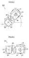
- Figs. 5(a) and 5(b) are perspective views showing the schematic configuration of a projector device, which is a second preferred embodiment of the invention.
- Figs. 6(a) and 6(b) are front views showing the configuration of its optical system.
- Figs. 5(a) and 6(a) illustrate a state in which the projector device is used
- Figs. 5(b) and 6(b) illustrate a state in which it is not used.
- the same members as in the above-described projector device 10 in the first mode of implementing the invention are assigned respectively the same reference signs.
- the DMD 20 is fixed to the rotating frame 14.
- This DMD 20 is fixed to the rotating frame 14 in advance at such an angle that illuminating light emitted from the TIR prism 18 come incident in a predetermined direction (the direction at an angle of 45° to the long side of the DMD 20)a predetermined incidence angle (20°).
- the DMD 20 is fixed to the rotating frame 14 in advance at a prescribe angle to the optical axis LB so that the illuminating light emitted from the TIR prism 18 irradiate the surface of the DMD 20 in a direction inclined by 45° relative to the long side of the DMD 20 at an incidence angle of 20°.
- the long side of this DMD 20 takes on a horizontal state relative to its installation plane when the rotating frame 14 is rotated to an angle of 45° to the fixed frame 12.
- the projector device 60 embodying the invention as described above operates as follows.
- the projector device 60 in this mode of implementation takes one of two available forms depending on whether the device is used or not used.
- the device takes on a state in which the rotating frame 14 is inclined by 45° relative to the fixed frame 12 (used state) as shown in Figs. 5(a) and 6(a), and, when it is not used, the rotating frame 14 is laid horizontally relative to the fixed frame 12 (unused state) as shown in Figs. 5(b) and 6(b).
- the DMD 20 since the DMD 20 is installed in advance in such a manner that the illuminating light emitted from the TIR prism 18 come incident in a predetermined direction at a predetermined incidence angle, an image can be projected on a screen even in the unused state. However, as the DMD 20 is inclined in the unused state, the image projected on the screen is also inclined.
- the inclination of the image projected on the screen is corrected by appropriately rotating the rotating frame 14. If the rotating frame 14 here is inclined by 45° relative to the fixed frame 12 to bring the projector device into the used state, the long side of the DMD 20 will become horizontal. Accordingly, the image projected on the screen is cleared of the inclination.
- the projector device 60 in this mode of implementation can be configured in a compact way when it is not used, because it can take either of two available states depending on whether the device is used or not used.
- the device can be configured of a smaller number of reflecting mirrors than any conventional projector device whose optical system is fixed, the configuration of the optical system itself can be simplified, too.
- the whole optical system including the DMD 20 is rotated around the optical axis LA
- the same purpose can as well be attained by rotating it around the optical axis LB.
- the configuration is such that the whole optical system including the DMD 20 is rotated around a rotation axis vertical to the DMD 20, the same purpose can be attained.
- the optical axis LA of the illuminating optical system 16 is oriented parallel to the optical axis LB of the projecting optical system 22 by using the reflecting mirror 34
- the optical axis of the illuminating optical system 16 may as well be orthogonal to the optical axis LB of the projecting optical system 22.
- the parallel orientation of the optical axis LA of the illuminating optical system 16 to the optical axis LB of the projecting optical system 22 by using the reflecting mirror 34 also makes it possible to reduce the width of the projector device.
- the configuration of the projector device can be made more compact when it is not used by altering the arrangement of the illuminating optical system or the projecting optical system depending on whether the device is used or not used.
Landscapes
- Engineering & Computer Science (AREA)
- Multimedia (AREA)
- Signal Processing (AREA)
- Projection Apparatus (AREA)
Abstract
Description
Claims (5)
- A projector device (10, 60) in which illuminating light from a light source (28) is guided by an illuminating optical system (16) to a digital micromirror device (20) and irradiates the digital micromirror device (20) at a predetermined incidence angle and in a predetermined direction, and light modulated by the digital micromirror device (20) is projected by a projecting optical system (22) on a screen, wherein:the direction of irradiation of the digital micromirror device (20) with the illuminating light by the illuminating optical system (16) is made variable depending on whether the projector device (10, 60) is used or unused.
- The projector device (10, 60) as set forth in claim 1, wherein the direction of irradiation of the digital micromirror device (20) with the illuminating light by the illuminating optical system (16) is varied as the illuminating optical system (16) rotates around an optical axis (LB) of the projecting optical system (22).
- The projector device (10, 60) as set forth in claim 1 or 2, wherein the illuminating optical system (16) and the digital micromirror device (20) are arranged in an unused state so that the direction of irradiation of the digital micromirror device (20) by the illuminating optical system (16) is substantially horizontal relative to an installation plane of the projector device (10, 60).
- A projector device (60) in which illuminating light from a light source (28) is guided by an illuminating optical system (16) to a digital micromirror device (20) and irradiates the digital micromirror device (20) at a predetermined incidence angle and in a predetermined direction, and light modulated by the digital micromirror device (20) is projected by a projecting optical system (22) on a screen, wherein:the digital micromirror device (20) is provided rotatably around a rotation axis (LA, LB) vertical to the digital micromirror device (20), at least part of the illuminating optical system (16) is provided rotatably around the rotation axis (LA, LB) so as not to let the direction of irradiation of the digital micromirror device (20) from the illuminating optical system (16) vary, and when the projector device (60) is in use the inclination of the image projected on the screen is corrected by rotating at least part of the illuminating optical system (16) and the digital micromirror device (20) around the rotation axis (LA, LB).
- The projector device (60) as set forth in claim 4, wherein the illuminating optical system (16) is arranged substantially horizontally when the projector device (60) is not in use.
Applications Claiming Priority (2)
| Application Number | Priority Date | Filing Date | Title |
|---|---|---|---|
| JP2001162097A JP4126524B2 (en) | 2001-05-30 | 2001-05-30 | Projector device |
| JP2001162097 | 2001-05-30 |
Publications (3)
| Publication Number | Publication Date |
|---|---|
| EP1263223A2 true EP1263223A2 (en) | 2002-12-04 |
| EP1263223A3 EP1263223A3 (en) | 2004-09-22 |
| EP1263223B1 EP1263223B1 (en) | 2010-01-20 |
Family
ID=19005274
Family Applications (1)
| Application Number | Title | Priority Date | Filing Date |
|---|---|---|---|
| EP02011846A Expired - Lifetime EP1263223B1 (en) | 2001-05-30 | 2002-05-28 | Projector device |
Country Status (4)
| Country | Link |
|---|---|
| US (1) | US6601959B2 (en) |
| EP (1) | EP1263223B1 (en) |
| JP (1) | JP4126524B2 (en) |
| DE (1) | DE60235137D1 (en) |
Cited By (2)
| Publication number | Priority date | Publication date | Assignee | Title |
|---|---|---|---|---|
| CN102037403B (en) * | 2008-05-22 | 2013-03-13 | 三洋电机株式会社 | Projection image display device |
| CN114321833A (en) * | 2020-10-09 | 2022-04-12 | 上海智瞳道和实业有限公司 | A vehicle lamp lighting method, system and vehicle lamp |
Families Citing this family (23)
| Publication number | Priority date | Publication date | Assignee | Title |
|---|---|---|---|---|
| US6767100B1 (en) * | 2001-12-19 | 2004-07-27 | Infocus Corporation | System and method employing reflective imaging devices for a projection display |
| TWI224206B (en) * | 2002-04-09 | 2004-11-21 | Benq Corp | Image display apparatus and method for recapturing off-state light |
| JP2004177654A (en) * | 2002-11-27 | 2004-06-24 | Fuji Photo Optical Co Ltd | Projection picture display device |
| KR20040072424A (en) * | 2003-02-12 | 2004-08-18 | 엘지전자 주식회사 | projection-type optical system of thin-type |
| TW553401U (en) * | 2003-02-24 | 2003-09-11 | Prodisc Technology Inc | Color wheel assembly |
| TW562152U (en) * | 2003-03-28 | 2003-11-11 | Coretronic Corp | Projection optical module |
| JP2005043739A (en) * | 2003-07-24 | 2005-02-17 | Olympus Corp | Projector |
| JP2005055812A (en) * | 2003-08-07 | 2005-03-03 | Olympus Corp | Projector device and desk having the projector device fitted therein |
| JP2005107062A (en) * | 2003-09-30 | 2005-04-21 | Plus Vision Corp | projector |
| US6805451B1 (en) * | 2003-11-12 | 2004-10-19 | Cinetron Technology Inc. | Horizontal/vertical dual-mode LCD projector |
| JP2005181579A (en) * | 2003-12-18 | 2005-07-07 | Olympus Corp | Lighting device and display device using the same |
| JP2005257790A (en) * | 2004-03-09 | 2005-09-22 | Olympus Corp | Illumination apparatus and image projection apparatus using the same |
| US6997564B2 (en) * | 2004-04-22 | 2006-02-14 | Raytheon Company | Digital projection display |
| US7055969B2 (en) * | 2004-04-29 | 2006-06-06 | Hewlett-Packard Development Company, L.P. | Reflective optical assembly |
| KR100612010B1 (en) * | 2004-05-14 | 2006-08-11 | 삼성전자주식회사 | Two-stage image forming apparatus and projection TV set using the same |
| JP2006058859A (en) * | 2004-07-23 | 2006-03-02 | Kazuji Yoshida | Image display apparatus |
| US20060077359A1 (en) * | 2004-10-10 | 2006-04-13 | Ying-Fang Lin | Projector with adjustable image offset |
| US7249855B2 (en) * | 2004-12-21 | 2007-07-31 | Hewlett-Packard Development Company, L.P. | System and method of image enhancement through light intensity modulation in digital projectors |
| JP4706261B2 (en) * | 2005-01-18 | 2011-06-22 | カシオ計算機株式会社 | Projection display device |
| JP5036144B2 (en) * | 2005-06-28 | 2012-09-26 | オリンパス株式会社 | Laser processing equipment |
| JP2007079044A (en) * | 2005-09-13 | 2007-03-29 | Sekinosu Kk | Projection lens unit |
| JP2012022033A (en) * | 2010-07-12 | 2012-02-02 | Sanyo Electric Co Ltd | Projection display device |
| CN103376634B (en) * | 2012-04-24 | 2015-11-18 | 中强光电股份有限公司 | Light source module and projection device |
Family Cites Families (20)
| Publication number | Priority date | Publication date | Assignee | Title |
|---|---|---|---|---|
| US5309188A (en) * | 1993-05-21 | 1994-05-03 | David Sarnoff Research Center, Inc. | Coupling prism assembly and projection system using the same |
| US5612753A (en) * | 1995-01-27 | 1997-03-18 | Texas Instruments Incorporated | Full-color projection display system using two light modulators |
| JP3197777B2 (en) * | 1995-03-24 | 2001-08-13 | 三洋電機株式会社 | Image display device |
| DE69626202T2 (en) * | 1995-05-11 | 2003-09-25 | Digital Projection Ltd., Middleton | PROJECTION DEVICE |
| JP3517044B2 (en) | 1995-09-28 | 2004-04-05 | 富士写真光機株式会社 | Optical system for video projector |
| US5642927A (en) * | 1995-11-22 | 1997-07-01 | Lightware, Inc. | LCD projector with retractable projection lens assembly |
| JPH09197341A (en) * | 1996-01-11 | 1997-07-31 | Nikon Corp | Projection display device |
| JP3331888B2 (en) * | 1996-04-25 | 2002-10-07 | 松下電器産業株式会社 | LCD projection equipment |
| US5669688A (en) * | 1996-06-07 | 1997-09-23 | Proxima Corporation | Display panel projector and method of using same |
| US5978051A (en) * | 1996-10-31 | 1999-11-02 | In Focus Systems Inc | Image projection system with variable display format |
| JP3372883B2 (en) | 1999-01-08 | 2003-02-04 | エヌイーシービューテクノロジー株式会社 | Projector device |
| JP3065058B1 (en) * | 1999-01-18 | 2000-07-12 | ミノルタ株式会社 | Optical system for projector |
| JP4447173B2 (en) * | 1999-04-23 | 2010-04-07 | コーニンクレッカ フィリップス エレクトロニクス エヌ ヴィ | Projection device |
| JP3769980B2 (en) * | 1999-05-21 | 2006-04-26 | セイコーエプソン株式会社 | Projection display |
| JP3743208B2 (en) * | 1999-05-21 | 2006-02-08 | セイコーエプソン株式会社 | Projection display |
| JP4016538B2 (en) * | 1999-07-27 | 2007-12-05 | コニカミノルタオプト株式会社 | Projection system |
| JP2001109067A (en) * | 1999-10-04 | 2001-04-20 | Minolta Co Ltd | Lighting equipment and projectors |
| IT1308865B1 (en) * | 1999-11-05 | 2002-01-11 | Sim2 Multimedia Spa | OPTICAL LIGHTING SYSTEM FOR VIDEO PROJECTOR. |
| JP2001330889A (en) * | 2000-05-23 | 2001-11-30 | Mitsubishi Electric Corp | Projection display device |
| ATE353528T1 (en) * | 2000-12-29 | 2007-02-15 | Texas Instruments Inc | OPTICAL MOTOR FOR SLM DISPLAY SYSTEMS WITH REFLECTIVE SCREEN OR TRANSMITTED SCREEN |
-
2001
- 2001-05-30 JP JP2001162097A patent/JP4126524B2/en not_active Expired - Fee Related
-
2002
- 2002-05-28 EP EP02011846A patent/EP1263223B1/en not_active Expired - Lifetime
- 2002-05-28 DE DE60235137T patent/DE60235137D1/en not_active Expired - Lifetime
- 2002-05-30 US US10/156,816 patent/US6601959B2/en not_active Expired - Fee Related
Cited By (2)
| Publication number | Priority date | Publication date | Assignee | Title |
|---|---|---|---|---|
| CN102037403B (en) * | 2008-05-22 | 2013-03-13 | 三洋电机株式会社 | Projection image display device |
| CN114321833A (en) * | 2020-10-09 | 2022-04-12 | 上海智瞳道和实业有限公司 | A vehicle lamp lighting method, system and vehicle lamp |
Also Published As
| Publication number | Publication date |
|---|---|
| EP1263223A3 (en) | 2004-09-22 |
| JP4126524B2 (en) | 2008-07-30 |
| DE60235137D1 (en) | 2010-03-11 |
| US6601959B2 (en) | 2003-08-05 |
| US20020180939A1 (en) | 2002-12-05 |
| JP2002350975A (en) | 2002-12-04 |
| EP1263223B1 (en) | 2010-01-20 |
Similar Documents
| Publication | Publication Date | Title |
|---|---|---|
| EP1263223B1 (en) | Projector device | |
| US6588908B2 (en) | Projector device | |
| JP3069860B1 (en) | Single-panel color projector | |
| JP4487240B2 (en) | Projection display optical system | |
| CN1228988C (en) | Projection display device | |
| US6795249B2 (en) | Reflective time-division image projector having a transmission color wheel | |
| US6827450B1 (en) | Scrolling color projection system | |
| JP2000206455A (en) | Projection display device | |
| JP2005115312A (en) | Reflective projection display system | |
| JP4790228B2 (en) | Illumination method and display device | |
| US20040070738A1 (en) | Image display projector | |
| US6118588A (en) | Illumination optical system and projector apparatus using the same | |
| JP2005099669A (en) | Projection display device | |
| EP1447992B1 (en) | Projecting optical system | |
| JP2003075768A (en) | Optical system for projector | |
| JP3896074B2 (en) | Color projector, color wheel used in the color projector, and display control method | |
| JP5298698B2 (en) | Projection display | |
| JP2002182128A (en) | Image projection color filter device and image projection device | |
| JP2003233127A (en) | Illumination method and apparatus for projection system | |
| JP2006163281A (en) | Projector device | |
| JP2003149599A (en) | Projection display device | |
| JPH11133504A (en) | Projection optical device | |
| US20020140908A1 (en) | Single-panel projection display device | |
| JPH11271706A (en) | Illumination optical system and projector device using the same | |
| JP2001133881A (en) | Optical unit and reflection type projector device using the same |
Legal Events
| Date | Code | Title | Description |
|---|---|---|---|
| PUAI | Public reference made under article 153(3) epc to a published international application that has entered the european phase |
Free format text: ORIGINAL CODE: 0009012 |
|
| AK | Designated contracting states |
Kind code of ref document: A2 Designated state(s): AT BE CH CY DE DK ES FI FR GB GR IE IT LI LU MC NL PT SE TR |
|
| AX | Request for extension of the european patent |
Free format text: AL;LT;LV;MK;RO;SI |
|
| PUAL | Search report despatched |
Free format text: ORIGINAL CODE: 0009013 |
|
| AK | Designated contracting states |
Kind code of ref document: A3 Designated state(s): AT BE CH CY DE DK ES FI FR GB GR IE IT LI LU MC NL PT SE TR |
|
| AX | Request for extension of the european patent |
Extension state: AL LT LV MK RO SI |
|
| 17P | Request for examination filed |
Effective date: 20050128 |
|
| RAP1 | Party data changed (applicant data changed or rights of an application transferred) |
Owner name: FUJINON CORPORATION |
|
| AKX | Designation fees paid |
Designated state(s): DE |
|
| GRAP | Despatch of communication of intention to grant a patent |
Free format text: ORIGINAL CODE: EPIDOSNIGR1 |
|
| GRAS | Grant fee paid |
Free format text: ORIGINAL CODE: EPIDOSNIGR3 |
|
| GRAA | (expected) grant |
Free format text: ORIGINAL CODE: 0009210 |
|
| AK | Designated contracting states |
Kind code of ref document: B1 Designated state(s): DE |
|
| REF | Corresponds to: |
Ref document number: 60235137 Country of ref document: DE Date of ref document: 20100311 Kind code of ref document: P |
|
| PLBE | No opposition filed within time limit |
Free format text: ORIGINAL CODE: 0009261 |
|
| STAA | Information on the status of an ep patent application or granted ep patent |
Free format text: STATUS: NO OPPOSITION FILED WITHIN TIME LIMIT |
|
| 26N | No opposition filed |
Effective date: 20101021 |
|
| PGFP | Annual fee paid to national office [announced via postgrant information from national office to epo] |
Ref country code: DE Payment date: 20130522 Year of fee payment: 12 |
|
| REG | Reference to a national code |
Ref country code: DE Ref legal event code: R119 Ref document number: 60235137 Country of ref document: DE |
|
| REG | Reference to a national code |
Ref country code: DE Ref legal event code: R119 Ref document number: 60235137 Country of ref document: DE Effective date: 20141202 |
|
| PG25 | Lapsed in a contracting state [announced via postgrant information from national office to epo] |
Ref country code: DE Free format text: LAPSE BECAUSE OF NON-PAYMENT OF DUE FEES Effective date: 20141202 |