EP1263222A2 - Projector device - Google Patents
Projector device Download PDFInfo
- Publication number
- EP1263222A2 EP1263222A2 EP02011844A EP02011844A EP1263222A2 EP 1263222 A2 EP1263222 A2 EP 1263222A2 EP 02011844 A EP02011844 A EP 02011844A EP 02011844 A EP02011844 A EP 02011844A EP 1263222 A2 EP1263222 A2 EP 1263222A2
- Authority
- EP
- European Patent Office
- Prior art keywords
- dmd
- angle
- plane
- incidence
- light
- Prior art date
- Legal status (The legal status is an assumption and is not a legal conclusion. Google has not performed a legal analysis and makes no representation as to the accuracy of the status listed.)
- Withdrawn
Links
- 230000003287 optical effect Effects 0.000 claims abstract description 56
- 239000011159 matrix material Substances 0.000 description 3
- 230000005540 biological transmission Effects 0.000 description 2
- 230000001678 irradiating effect Effects 0.000 description 2
- 230000015572 biosynthetic process Effects 0.000 description 1
- 238000010276 construction Methods 0.000 description 1
- 230000004907 flux Effects 0.000 description 1
- 238000009434 installation Methods 0.000 description 1
- 238000000034 method Methods 0.000 description 1
- 238000012986 modification Methods 0.000 description 1
- 230000004048 modification Effects 0.000 description 1
- 230000008569 process Effects 0.000 description 1
- 230000009467 reduction Effects 0.000 description 1
Images


Classifications
-
- H—ELECTRICITY
- H04—ELECTRIC COMMUNICATION TECHNIQUE
- H04N—PICTORIAL COMMUNICATION, e.g. TELEVISION
- H04N9/00—Details of colour television systems
- H04N9/12—Picture reproducers
- H04N9/31—Projection devices for colour picture display, e.g. using electronic spatial light modulators [ESLM]
- H04N9/3141—Constructional details thereof
-
- H—ELECTRICITY
- H04—ELECTRIC COMMUNICATION TECHNIQUE
- H04N—PICTORIAL COMMUNICATION, e.g. TELEVISION
- H04N5/00—Details of television systems
- H04N5/74—Projection arrangements for image reproduction, e.g. using eidophor
- H04N5/7416—Projection arrangements for image reproduction, e.g. using eidophor involving the use of a spatial light modulator, e.g. a light valve, controlled by a video signal
- H04N5/7458—Projection arrangements for image reproduction, e.g. using eidophor involving the use of a spatial light modulator, e.g. a light valve, controlled by a video signal the modulator being an array of deformable mirrors, e.g. digital micromirror device [DMD]
-
- H—ELECTRICITY
- H04—ELECTRIC COMMUNICATION TECHNIQUE
- H04N—PICTORIAL COMMUNICATION, e.g. TELEVISION
- H04N9/00—Details of colour television systems
- H04N9/12—Picture reproducers
- H04N9/31—Projection devices for colour picture display, e.g. using electronic spatial light modulators [ESLM]
- H04N9/3102—Projection devices for colour picture display, e.g. using electronic spatial light modulators [ESLM] using two-dimensional electronic spatial light modulators
Definitions
- the present invention relates to a projector device, and more particularly to a projector device for projecting images on a screen by using a digital micromirror device (DMD).
- DMD digital micromirror device
- a DMD is configured of a large number of micromirrors arranged in a matrix, in which each micromirror constitutes one pixel of a displayed image.
- Each micromirror takes one of two inclined states, an ON state and an OFF state. In the ON state, illuminating light is reflected into a projecting optical system, while in the OFF state it is projected away from the projecting optical system. Therefore, in a projector device using a DMD, the projecting optical system projects only the light reflected by micromirrors in the ON state, resulting in the formation of a displayed image composed of a pattern of different levels of brightness on the screen.
- Fig. 5 shows a plan of a micromirror drive structure in a DMD
- Fig. 6 shows the 6-6 section in Fig. 5.
- the drawings show expanded views of one extracted out of many micromirrors constituting the DMD, which actually is configured of a large number of micromirrors arranged in a matrix.
- a micromirror 2 of a DMD 1 can take either an ON state inclined by +12° or an OFF state inclined by -12° to the DMD surface by turning around a rotation axis ab.
- This rotation axis ab of the micromirror 2 is set in a direction inclined by 45° to the long (or short) side of the DMD, and illuminating light L o irradiates the surface of the DMD at an incidence angle of 24° in a direction orthogonal to this rotation axis ab.
- the illuminating light L o irradiating the DMD if reflected by the micromirror 2 in the ON state, turns into projecting light L 1 whose angle of reflection by the DMD surface is 0° or, if reflected by the micromirror 2 in the OFF state, turns into projecting light L 2 whose angle of reflection by the DMD surface is -48°.
- Only the projecting light L 1 which is a luminous flux reflected by the micromirror 2 in the ON state at 0° in the angle of reflection, comes incident on the projecting optical system, and a displayed image composed of a pattern of different levels of brightness is formed on the screen.
- Known projector devices using such a DMD include ones disclosed in Japanese Patent Application Publication Nos. 9-98442 and 12-206452.
- the illuminating optical system has to be configured to meet two constraints that the illuminating light L o should be brought to incidence in a direction orthogonal to the rotation axis of the micromirror 2 (a direction inclined by 45° to the long or short side of the DMD 1) and the illuminating light L o should further be brought to incidence at an angle of 24° to the surface of the DMD 1.
- a total internal reflection prism (TIR prism) is used to guide the illuminating light onto the DMD 1.
- TIR prism total internal reflection prism
- light emitted from a light source 3 is condensed into a rod integrator 5 via a color wheel 4, guided by a first mirror 6 and a second mirror 7 to a TIR prism 8 and totally reflected by that TIR prism 8 thereby to irradiate the DMD 1 in a predetermined direction (a direction inclined by 45° to the long or short side of the DMD 1) and at a predetermined incidence angle (24°).
- optical modulation is performed, and the light transmitted by the TIR prism 8 after that optical modulation is projected by a projecting optical system 9 onto a screen.
- This TIR prism 8 is configured of a first prism 8A and a second prism 8B.
- the DMD 1 is irradiated in the predetermined direction and the predetermined incidence angle, and the reflected light from the DMD 1 is guided to the projecting optical system 9 by causing it to be wholly transmitted by the total reflection plane P of the first prism 8A.
- the inclination angle ⁇ of the total reflection plane P is so set as to totally reflect the incident illuminating light and to totally transmit the reflected light from the DMD 1 and the direction of the total reflection plane P is such that the projection line representing its normal vector as viewed in the direction vertical to the surface of the DMD 1 forms an angle of 45° to the long side of the DMD 1 (in Fig. 9, the normal vector of the total reflection plane shown in the front view and the rear view corresponds to the projection line representing the normal vector of the total reflection plane as viewed in the direction vertical to the surface of the DMD 1).
- the illuminating light as is the total reflection plane normal vector, is brought to incidence on this TIR prism 8 at a predetermined incidence angle (50.2° here) in a direction at 45° to the long side of the DMD 1, and caused to be reflected by the total reflection plane 4P to be guided to the DMD 1.
- this projector device since the illuminating light should be brought to incidence on the TIR prism 8 in a direction at 45° to the long side of the DMD 1 as shown in Fig. 8 and Fig. 9, involves the disadvantage of being increased in thickness.
- An object of the present invention attempted in view of this circumstance, is to provide a projector device that permits a reduction in thickness.
- the present invention is directed to a projector device in which light from a light source is guided by an illuminating optical system to a total internal reflection prism, the light totally reflected by the total internal reflection prism is optically modulated by having the light reflected by a digital micromirror device, and the light transmitted by the total internal reflection prism after the optical modulation is projected by a projecting optical system on a screen, wherein: the total internal reflection prism has a total reflection plane which totally reflects illuminating light to guide the illuminating light to the digital micromirror device and totally transmits the light having undergone optical modulation by the digital micromirror device, and is so arranged relative to the digital micromirror device that a projection line representing a normal vector of the total reflection plane as viewed in a direction vertical to a surface of the digital micromirror device forms an angle smaller than 45° to one of a long side and a short side of the digital micromirror device; and the illuminating optical
- the TIR prism is so arranged relative to the DMD that a projection line representing the normal vector of the total reflection plane as viewed in a direction vertical to the surface of the DMD forms an angle smaller than 45° to the long or short side of the DMD.
- the illuminating optical system so brings the illuminating light into incidence that a projection line representing the optical axis of the illuminating light emitted from the TIR prism to the DMD, as viewed in a direction vertical to the surface of the DMD, forms an angle of 45° to the long or short side of the DMD.
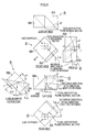
- Fig. 1 and Fig. 2 respectively show a plan and a rear view of a projector device, which is a preferred embodiment of the invention.
- a projector device 10 in this mode of implementing the invention comprises an illuminating optical system 16, a TIR prism 18, a DMD 20 and an projecting optical system 22.
- the illuminating optical system 16 comprises a light source 28, a color wheel 29, a rod integrator 30, relay lenses 32 and a reflecting mirror 34, all arranged on an optical axis LA (the optical axis of the illuminating optical system). Illuminating light emitted from the light source 28 is brought to incidence on the rod integrator 30 via the color wheel 29. Its brightness is uniformized by being reflected within the rod integrator 30 a plurality of times, and the uniformized illuminating light is emitted to the relay lenses 32.
- the relay lenses 32 condense the illuminating light emitted from the rod integrator 30, and this condensed illuminating light is brought to incidence on the TIR prism 18 by being reflected by the reflecting mirror 34.
- the TIR prism 18 totally reflects the illuminating light guided from the light source 28 by the illuminating optical system to guide it to the DMD 20, and totally transmits light having undergone optical modulation by the DMD 20 and guides it to the projecting optical system 22. In this process, the TIR prism 18 totally reflects the illuminating light brought to incidence in a predetermined direction to irradiate the surface of the DMD 20 at an incidence angle of 24° in a direction forming an angle of 45° to the long side of the DMD 20.
- the configuration of this TIR prism 18 will be described in detail afterwards.
- the DMD 20 comprises a large number of micromirrors arranged in a matrix.
- the illuminating light is optically modulated by subjecting each micromirror to ON/OFF control.
- This DMD 20 is installed vertically to an optical axis LB to keep its long side horizontal relative to the installation plane.
- the projecting optical system 22 arranged on the optical axis LB, projects in an enlarged size projecting light transmitted by the TIR prism 18 after being optically modulated by the DMD 20.
- This projecting optical system 22 is provided with a focusing function for focusing the image to be projected.
- the illuminating light emitted from that light source 28 is guided to the TIR prism 18 via the rod integrator 30, the relay lenses 32 and the reflecting mirror 34 and, after being totally reflected by the TIR prism 18, irradiates the surface of the DMD 20 in a predetermined direction at a predetermined angle of incidence.
- the DMD 20 reflects only the part of light required for a predetermined image to the projecting optical system 22, and that projecting light is enlarged by the projecting optical system 22 and projected on a screen (not shown).
- Fig. 3 and Fig. 4 respectively show a perspective view and a development of the configuration of the TIR prism 18.
- the TIR prism 18 in this preferred embodiment of the invention comprises a first prism 36 and a second prism 38.
- the first prism 36 and the second prism 38 are so arranged that a plane 36A of the first prism 36 and a plane 38A of the second prism 38 be opposite each other via an air layer (air gap) between them.
- a plane 36C of the first prism 36 and a plane 38C of the second prism 38 form the same plane together, and these plane 36C and plane 38C are arranged to be parallel to the surface of the DMD 20 and, at the same time a plane 38B of the second prism 38 is also arranged to be parallel to the surface of the DMD 20.
- the illuminating light is brought to incidence on the first prism 36 to be vertical to its plane 36B and, after being totally reflected by the plane 36A, emitted from the plane 36C toward the DMD 20. Then, the projecting light reflected by the DMD 20 is totally transmitted by the plane 36A of the first prism 36 and the second prism 38 to be guided to the projecting optical system 22.
- the plane 36A of this first prism 36 (hereinafter to be referred to as the "total reflection plane") is formed at an angle of inclination ⁇ ( ⁇ is the angle formed by the surface of the DMD 20 and the total reflection plane 36A) permitting total reflection of the illuminating light brought to incidence vertically on the plane 36B (hereinafter to be referred to as the "incidence plane") and total transmission of the reflected light from the DMD 20, and in a predetermined direction so that a projection line representing the normal vector of the total reflection plane (hereinafter to be referred to as the "total reflection plane normal vector") as viewed in a direction vertical to the surface of the DMD 20 forms an angle ⁇ smaller than 45° to the long side of the DMD 20 (in Fig. 4, the total reflection plane normal vector illustrated in the front view and the rear view corresponds to the projection line representing the total reflection plane normal vector as viewed in the direction vertical to the surface of the DMD 20).
- the incidence plane 36B of the first prism 36 is so formed that the total reflection of the illuminating light coming vertically incident on that plane by the total reflection plane 36A and the emission of the totally reflected light from the plane 36C (hereinafter to be referred to as the "emission plane") toward the DMD 20 cause the surface of the DMD 20 to be irradiated at an incidence angle of 24° to the surface of the DMD 20 in a direction forming an angle of 45° to the long (or short) side of the DMD 20.
- the optical axis L' illustrated in the front view corresponds to the projection line representing the optical axis L' as viewed in the direction vertical to the surface of the DMD 20) to form an angle of 45° to the long (or short) side of the DMD 20, it is necessary to bring into incidence the illuminating light coming incident from the illuminating optical system 16 at a predetermined incidence angle ⁇ and in a direction forming a predetermined angle b to the long side of the DMD 20, and the incidence plane 36B is formed as a plane orthogonal to the optical axis L of the incident light.
- the illuminating optical system 16 need not bring the illuminating light into incidence on the TIR prism in a direction forming an angle of 45° to the long side of the DMD 20 as according to the prior art, and thereby enables the projector device to be reduced in thickness.
- the illuminating light brought to incidence on the TIR prism 18 by the illuminating optical system 16 is enabled to come incident at an angle smaller than 45° to the long side of the DMD 20 as illustrated in Fig. 2 through Fig. 4, thereby enabling the projector device to be reduced in thickness.
- the number of reflecting mirrors for guiding the illuminating light to the TIR prism 18 can also be reduced, thereby enabling the projector device to be simplified (see Fig. 2 and Fig. 8).
- the invention can as well be applied to a case in which the angle of inclination of the micromirrors is ⁇ 10°.
- the illuminating light is brought to incidence at an incidence angle of 20° to the surface of the DMD 20 in a direction forming an angle of 45° to the long or short side of the DMD 20.
- TIR prism to be applied to a projector device pertaining to the present invention.
- the example explained here is a TIR prism applicable to a projector device using a DMD whose micromirrors are inclined at ⁇ 12°.
- the illuminating light to irradiate the surface of the DMD 20 at an incidence angle of 24° to the surface of the DMD 20 in a direction forming an angle of 45° to the long or short side of the DMD 20.
- the illuminating light is brought to incidence vertically on the incidence plane 36B of the first prism 36, totally reflected by the total reflection plane 36A, and guided to the DMD 20. Then, the projecting light reflected by the DMD 20 is totally transmitted by the total reflection plane 36A of the first prism 36 and the second prism 38 and guided to the projecting optical system 22.
- the total reflection plane 36A of the first prism 36 is oriented in a predetermined direction so that the angle ⁇ formed between the projection line representing the total reflection plane normal vector as viewed in the direction vertical to the surface of the DMD 20 and the long side of the DMD 20 be equal to 3°.
- This angle ⁇ 3° is set at a degree smaller than 45°, and preferably should be close to 0° as long as the requirement of total reflection is met.
- the incidence plane 36B of the first prism 36 is formed to be irradiated at an incidence angle of 24° to the surface of the DMD 20 in a direction forming an angle of 45° to the long side of the DMD 20 by the total reflection of the illuminating light brought to incidence vertically on the incidence plane 36B by the illuminating optical system 16, its total reflection by the aforementioned total reflection plane 36A and emission from the emission plane 36C toward the DMD 20.
- the illuminating optical system can be configured in a substantially horizontal state, and accordingly the projector device can be reduced in thickness.
- the illuminating optical system need not bring the illuminating light into incidence on the TIR prism in a direction forming an angle of 45° to the long or short side of the DMD 20 as according to the prior art, and therefore the projector device can be reduced in thickness.
Abstract
Description
- The present invention relates to a projector device, and more particularly to a projector device for projecting images on a screen by using a digital micromirror device (DMD).
- A DMD is configured of a large number of micromirrors arranged in a matrix, in which each micromirror constitutes one pixel of a displayed image. Each micromirror takes one of two inclined states, an ON state and an OFF state. In the ON state, illuminating light is reflected into a projecting optical system, while in the OFF state it is projected away from the projecting optical system. Therefore, in a projector device using a DMD, the projecting optical system projects only the light reflected by micromirrors in the ON state, resulting in the formation of a displayed image composed of a pattern of different levels of brightness on the screen.
- Fig. 5 shows a plan of a micromirror drive structure in a DMD, and Fig. 6 shows the 6-6 section in Fig. 5. The drawings show expanded views of one extracted out of many micromirrors constituting the DMD, which actually is configured of a large number of micromirrors arranged in a matrix.
- As illustrated in Fig. 5, a
micromirror 2 of aDMD 1 can take either an ON state inclined by +12° or an OFF state inclined by -12° to the DMD surface by turning around a rotation axis ab. This rotation axis ab of themicromirror 2 is set in a direction inclined by 45° to the long (or short) side of the DMD, and illuminating light Lo irradiates the surface of the DMD at an incidence angle of 24° in a direction orthogonal to this rotation axis ab. The illuminating light Lo irradiating the DMD, if reflected by themicromirror 2 in the ON state, turns into projecting light L1 whose angle of reflection by the DMD surface is 0° or, if reflected by themicromirror 2 in the OFF state, turns into projecting light L2 whose angle of reflection by the DMD surface is -48°. Only the projecting light L1, which is a luminous flux reflected by themicromirror 2 in the ON state at 0° in the angle of reflection, comes incident on the projecting optical system, and a displayed image composed of a pattern of different levels of brightness is formed on the screen. Known projector devices using such a DMD include ones disclosed in Japanese Patent Application Publication Nos. 9-98442 and 12-206452. - Incidentally, for a projector device using a DMD as stated above, on account of the above-described structure of the
DMD 1, the illuminating optical system has to be configured to meet two constraints that the illuminating light Lo should be brought to incidence in a direction orthogonal to the rotation axis of the micromirror 2 (a direction inclined by 45° to the long or short side of the DMD 1) and the illuminating light Lo should further be brought to incidence at an angle of 24° to the surface of theDMD 1. - For this reason, in a projector device according to the prior art, as shown in Fig. 7 and Fig. 8, a total internal reflection prism (TIR prism) is used to guide the illuminating light onto the
DMD 1. Thus, light emitted from alight source 3 is condensed into arod integrator 5 via acolor wheel 4, guided by afirst mirror 6 and asecond mirror 7 to aTIR prism 8 and totally reflected by thatTIR prism 8 thereby to irradiate theDMD 1 in a predetermined direction (a direction inclined by 45° to the long or short side of the DMD 1) and at a predetermined incidence angle (24°). By causing the illuminating light irradiating theDMD 1 in this way to be reflected by theDMD 1, optical modulation is performed, and the light transmitted by theTIR prism 8 after that optical modulation is projected by a projectingoptical system 9 onto a screen. - This
TIR prism 8, as shown in Fig. 9, is configured of afirst prism 8A and asecond prism 8B. By causing illuminating light guided in from an illuminating optical system to be totally reflected by the total reflection plane P of thefirst prism 8A, theDMD 1 is irradiated in the predetermined direction and the predetermined incidence angle, and the reflected light from theDMD 1 is guided to the projectingoptical system 9 by causing it to be wholly transmitted by the total reflection plane P of thefirst prism 8A. - Now, in the
conventional TIR prism 8, as illustrated in Fig. 9, the inclination angle α of the total reflection plane P is so set as to totally reflect the incident illuminating light and to totally transmit the reflected light from theDMD 1 and the direction of the total reflection plane P is such that the projection line representing its normal vector as viewed in the direction vertical to the surface of theDMD 1 forms an angle of 45° to the long side of the DMD 1 (in Fig. 9, the normal vector of the total reflection plane shown in the front view and the rear view corresponds to the projection line representing the normal vector of the total reflection plane as viewed in the direction vertical to the surface of the DMD 1). The illuminating light, as is the total reflection plane normal vector, is brought to incidence on thisTIR prism 8 at a predetermined incidence angle (50.2° here) in a direction at 45° to the long side of theDMD 1, and caused to be reflected by the total reflection plane 4P to be guided to theDMD 1. - However, this projector device according to the prior art, since the illuminating light should be brought to incidence on the
TIR prism 8 in a direction at 45° to the long side of theDMD 1 as shown in Fig. 8 and Fig. 9, involves the disadvantage of being increased in thickness. - An object of the present invention, attempted in view of this circumstance, is to provide a projector device that permits a reduction in thickness.
- In order to achieve the object stated above, the present invention is directed to a projector device in which light from a light source is guided by an illuminating optical system to a total internal reflection prism, the light totally reflected by the total internal reflection prism is optically modulated by having the light reflected by a digital micromirror device, and the light transmitted by the total internal reflection prism after the optical modulation is projected by a projecting optical system on a screen, wherein: the total internal reflection prism has a total reflection plane which totally reflects illuminating light to guide the illuminating light to the digital micromirror device and totally transmits the light having undergone optical modulation by the digital micromirror device, and is so arranged relative to the digital micromirror device that a projection line representing a normal vector of the total reflection plane as viewed in a direction vertical to a surface of the digital micromirror device forms an angle smaller than 45° to one of a long side and a short side of the digital micromirror device; and the illuminating optical system so brings the illuminating light into incidence on the total reflection plane that a projection line representing the optical axis of the illuminating light emitted from the total internal reflection prism to the digital micromirror device, as viewed in the direction vertical to the surface of the digital micromirror device, forms an angle of 45° to the one of the long side and the short side of the digital micromirror device.
- According to the invention, the TIR prism is so arranged relative to the DMD that a projection line representing the normal vector of the total reflection plane as viewed in a direction vertical to the surface of the DMD forms an angle smaller than 45° to the long or short side of the DMD. Relative to the total reflection plane so arranged, the illuminating optical system so brings the illuminating light into incidence that a projection line representing the optical axis of the illuminating light emitted from the TIR prism to the DMD, as viewed in a direction vertical to the surface of the DMD, forms an angle of 45° to the long or short side of the DMD. This dispenses with the need to bring the illuminating light into incidence on the TIR prism in a direction forming an angle of 45° to the long or short side of the DMD as according to the prior art, and thereby enables the projector device to be reduced in thickness.
- The nature of this invention, as well as other objects and advantages thereof, will be explained in the following with reference to the accompanying drawings, in which like reference characters designate the same or similar parts throughout the figures and wherein:
- Fig. 1 shows a plan of a projector device, which is a preferred embodiment of the invention;
- Fig. 2 shows a rear view of the projector device, which is the preferred embodiment of the invention;
- Fig. 3 shows a perspective view of the configuration of a TIR prism;
- Fig. 4 is a development illustrating the configuration of the TIR prism;
- Fig. 5 shows a plan of a micromirror drive structure in a DMD;
- Fig. 6 shows the 6-6 section in Fig. 5.
- Fig. 7 shows a plan of a projector device, which is an embodiment of the prior art;
- Fig. 8 shows a rear view of the projector device, which is the embodiment of the prior art; and
- Fig. 9 is a development illustrating the configuration of a TIR prism according to the prior art.
-
- A projector device, which is a preferred embodiment of the present invention, will be described in detail below with reference to accompanying drawings.
- Fig. 1 and Fig. 2 respectively show a plan and a rear view of a projector device, which is a preferred embodiment of the invention. As shown in these drawings, a
projector device 10 in this mode of implementing the invention comprises an illuminating optical system 16, aTIR prism 18, aDMD 20 and an projectingoptical system 22. - The illuminating optical system 16 comprises a
light source 28, acolor wheel 29, arod integrator 30,relay lenses 32 and areflecting mirror 34, all arranged on an optical axis LA (the optical axis of the illuminating optical system). Illuminating light emitted from thelight source 28 is brought to incidence on therod integrator 30 via thecolor wheel 29. Its brightness is uniformized by being reflected within the rod integrator 30 a plurality of times, and the uniformized illuminating light is emitted to therelay lenses 32. Therelay lenses 32 condense the illuminating light emitted from therod integrator 30, and this condensed illuminating light is brought to incidence on theTIR prism 18 by being reflected by thereflecting mirror 34. - The
TIR prism 18 totally reflects the illuminating light guided from thelight source 28 by the illuminating optical system to guide it to theDMD 20, and totally transmits light having undergone optical modulation by theDMD 20 and guides it to the projectingoptical system 22. In this process, theTIR prism 18 totally reflects the illuminating light brought to incidence in a predetermined direction to irradiate the surface of theDMD 20 at an incidence angle of 24° in a direction forming an angle of 45° to the long side of theDMD 20. The configuration of thisTIR prism 18 will be described in detail afterwards. - The
DMD 20 comprises a large number of micromirrors arranged in a matrix. The illuminating light is optically modulated by subjecting each micromirror to ON/OFF control. This DMD 20 is installed vertically to an optical axis LB to keep its long side horizontal relative to the installation plane. - The projecting
optical system 22, arranged on the optical axis LB, projects in an enlarged size projecting light transmitted by theTIR prism 18 after being optically modulated by theDMD 20. This projectingoptical system 22 is provided with a focusing function for focusing the image to be projected. - In the
projector device 10 configured as described above, when thelight source 28 is turned on, the illuminating light emitted from thatlight source 28 is guided to theTIR prism 18 via therod integrator 30, therelay lenses 32 and the reflectingmirror 34 and, after being totally reflected by theTIR prism 18, irradiates the surface of theDMD 20 in a predetermined direction at a predetermined angle of incidence. TheDMD 20 reflects only the part of light required for a predetermined image to the projectingoptical system 22, and that projecting light is enlarged by the projectingoptical system 22 and projected on a screen (not shown). - Fig. 3 and Fig. 4 respectively show a perspective view and a development of the configuration of the
TIR prism 18. - As illustrated in these drawings, the
TIR prism 18 in this preferred embodiment of the invention comprises afirst prism 36 and asecond prism 38. Thefirst prism 36 and thesecond prism 38 are so arranged that aplane 36A of thefirst prism 36 and aplane 38A of thesecond prism 38 be opposite each other via an air layer (air gap) between them. Further, aplane 36C of thefirst prism 36 and aplane 38C of thesecond prism 38 form the same plane together, and theseplane 36C andplane 38C are arranged to be parallel to the surface of theDMD 20 and, at the same time aplane 38B of thesecond prism 38 is also arranged to be parallel to the surface of theDMD 20. - In this
TIR prism 18, the illuminating light is brought to incidence on thefirst prism 36 to be vertical to itsplane 36B and, after being totally reflected by theplane 36A, emitted from theplane 36C toward theDMD 20. Then, the projecting light reflected by theDMD 20 is totally transmitted by theplane 36A of thefirst prism 36 and thesecond prism 38 to be guided to the projectingoptical system 22. - The
plane 36A of this first prism 36 (hereinafter to be referred to as the "total reflection plane") is formed at an angle of inclination α (α is the angle formed by the surface of theDMD 20 and thetotal reflection plane 36A) permitting total reflection of the illuminating light brought to incidence vertically on theplane 36B (hereinafter to be referred to as the "incidence plane") and total transmission of the reflected light from theDMD 20, and in a predetermined direction so that a projection line representing the normal vector of the total reflection plane (hereinafter to be referred to as the "total reflection plane normal vector") as viewed in a direction vertical to the surface of theDMD 20 forms an angle γ smaller than 45° to the long side of the DMD 20 (in Fig. 4, the total reflection plane normal vector illustrated in the front view and the rear view corresponds to the projection line representing the total reflection plane normal vector as viewed in the direction vertical to the surface of the DMD 20). - On the other hand, the
incidence plane 36B of thefirst prism 36 is so formed that the total reflection of the illuminating light coming vertically incident on that plane by thetotal reflection plane 36A and the emission of the totally reflected light from theplane 36C (hereinafter to be referred to as the "emission plane") toward theDMD 20 cause the surface of theDMD 20 to be irradiated at an incidence angle of 24° to the surface of theDMD 20 in a direction forming an angle of 45° to the long (or short) side of theDMD 20. Thus, in order for the optical axis L' of the illuminating light emitted from theemission plane 36C toward theDMD 20 to have an incidence angle of 24° to the surface of theDMD 20 and for the projection line representing the optical axis L' as viewed in the direction vertical to the surface of the DMD (in Fig. 4, the optical axis L' illustrated in the front view corresponds to the projection line representing the optical axis L' as viewed in the direction vertical to the surface of the DMD 20) to form an angle of 45° to the long (or short) side of theDMD 20, it is necessary to bring into incidence the illuminating light coming incident from the illuminating optical system 16 at a predetermined incidence angle β and in a direction forming a predetermined angle b to the long side of theDMD 20, and theincidence plane 36B is formed as a plane orthogonal to the optical axis L of the incident light. - In the
TIR prism 18 configured as described above, the illuminating optical system 16 need not bring the illuminating light into incidence on the TIR prism in a direction forming an angle of 45° to the long side of theDMD 20 as according to the prior art, and thereby enables the projector device to be reduced in thickness. - Thus in the
TIR prism 18 in this embodiment of the invention, by so forming thetotal reflection plane 36A relative to theDMD 20 that the projection line representing the total reflection plane normal vector as viewed in the direction vertical to the surface of theDMD 20 be at an angle smaller than 45° to the long side of the DMD 20 (γ < 45°), the illuminating light brought to incidence on theTIR prism 18 by the illuminating optical system 16 is enabled to come incident at an angle smaller than 45° to the long side of theDMD 20 as illustrated in Fig. 2 through Fig. 4, thereby enabling the projector device to be reduced in thickness. - Further by enabling the illuminating light to come incident on the
TIR prism 18 at an angle smaller than 45° to the long side of theDMD 20, the number of reflecting mirrors for guiding the illuminating light to theTIR prism 18 can also be reduced, thereby enabling the projector device to be simplified (see Fig. 2 and Fig. 8). - Although this embodiment of the invention has been described with reference to an example in which the angle of inclination of the micromirrors constituting the
DMD 20 is ±12°, the invention can as well be applied to a case in which the angle of inclination of the micromirrors is ±10°. In this case, the illuminating light is brought to incidence at an incidence angle of 20° to the surface of theDMD 20 in a direction forming an angle of 45° to the long or short side of theDMD 20. - Next will be described an example of TIR prism to be applied to a projector device pertaining to the present invention.
- The example explained here is a TIR prism applicable to a projector device using a DMD whose micromirrors are inclined at ±12°.
- As described above, in a DMD whose micromirrors are inclined at ±12°, it is necessary for the illuminating light to irradiate the surface of the
DMD 20 at an incidence angle of 24° to the surface of theDMD 20 in a direction forming an angle of 45° to the long or short side of theDMD 20. - As illustrated in Fig. 3 and Fig. 4, the illuminating light is brought to incidence vertically on the
incidence plane 36B of thefirst prism 36, totally reflected by thetotal reflection plane 36A, and guided to theDMD 20. Then, the projecting light reflected by theDMD 20 is totally transmitted by thetotal reflection plane 36A of thefirst prism 36 and thesecond prism 38 and guided to the projectingoptical system 22. - The
total reflection plane 36A of thefirst prism 36 is formed at an inclination angle of α = 34.7° to the surface of theDMD 20. This inclination angle of α = 34.7° is set as an inclination angle permitting total reflection of the illuminating light brought to incidence vertically on theincidence plane 36B and total transmission of the reflected light from theDMD 20. - The
total reflection plane 36A of thefirst prism 36 is oriented in a predetermined direction so that the angle γ formed between the projection line representing the total reflection plane normal vector as viewed in the direction vertical to the surface of theDMD 20 and the long side of theDMD 20 be equal to 3°. This angle γ = 3° is set at a degree smaller than 45°, and preferably should be close to 0° as long as the requirement of total reflection is met. - On the other hand, the
incidence plane 36B of thefirst prism 36 is formed to be irradiated at an incidence angle of 24° to the surface of theDMD 20 in a direction forming an angle of 45° to the long side of theDMD 20 by the total reflection of the illuminating light brought to incidence vertically on theincidence plane 36B by the illuminating optical system 16, its total reflection by the aforementionedtotal reflection plane 36A and emission from theemission plane 36C toward theDMD 20. - Here, the
total reflection plane 36A, as described above, is formed to have an inclination angle of α = 34.7° to the surface of theDMD 20 and oriented in a predetermined direction so that the angle γ formed between the projection line representing the total reflection plane normal vector as viewed in the direction vertical to the surface of theDMD 20 and the long side of theDMD 20 be equal to 3°. In order for the illuminating light totally reflected by thetotal reflection plane 36A formed in such a way as to irradiate the surface of theDMD 20 at an incidence angle of 24° to the surface of theDMD 20 in a direction at an angle of 45° to the long side of theDMD 20, the illuminating light should be brought to incidence at an incidence angle of β = 47.3° to thetotal reflection plane 36A and in a direction at an angle of δ =13.5° to the long side of theDMD 20. Therefore, theincidence plane 36A of thefirst prism 36 is formed as a plane orthogonal to the optical axis L of the illuminating light satisfying this requirement. - In the
TIR prism 18 configured as described, since the illuminating light brought to incidence on theTIR prism 18 comes in a direction at an angle of δ =13.5° to the long side of theDMD 20, the illuminating optical system can be configured in a substantially horizontal state, and accordingly the projector device can be reduced in thickness. - As hitherto described, according to the present invention, the illuminating optical system need not bring the illuminating light into incidence on the TIR prism in a direction forming an angle of 45° to the long or short side of the
DMD 20 as according to the prior art, and therefore the projector device can be reduced in thickness. - It should be understood, however, that there is no intention to limit the invention to the specific forms disclosed, but on the contrary, the invention is to cover all modifications, alternate constructions and equivalents falling within the spirit and scope of the invention as expressed in the appended claims.
Claims (2)
- A projector device (10) in which light from a light source (28) is guided by an illuminating optical system (16) to a total internal reflection prism (18), the light totally reflected by the total internal reflection prism (18) is optically modulated by having the light reflected by a digital micromirror device (20), and the light transmitted by the total internal reflection prism (18) after the optical modulation is projected by a projecting optical system (22) on a screen, wherein:the total internal reflection prism (18) has a total reflection plane (36A) which totally reflects illuminating light to guide the illuminating light to the digital micromirror device (20) and totally transmits the light having undergone optical modulation by the digital micromirror device (20), and is so arranged relative to the digital micromirror device (20) that a projection line representing a normal vector of the total reflection plane (36A) as viewed in a direction vertical to a surface of the digital micromirror device (20) forms an angle (γ) smaller than 45° to one of a long side and a short side of the digital micromirror device (20); andthe illuminating optical system (16) so brings the illuminating light into incidence on the total reflection plane (36A) that a projection line representing the optical axis of the illuminating light emitted from the total internal reflection prism (18) to the digital micromirror device (20), as viewed in the direction vertical to the surface of the digital micromirror device (20), forms an angle of 45° to the one of the long side and the short side of the digital micromirror device (20).
- The projector device (10) as set forth in claim 1, wherein the total internal reflection prism (18) is so arranged relative to the digital micromirror device (20) that the projection line representing the normal vector of the total reflection plane (36A) as viewed in the direction vertical to the surface of the digital micromirror device (20) forms an angle of substantially 0° to the one of the long side and the short side of the digital micromirror device (20).
Applications Claiming Priority (2)
| Application Number | Priority Date | Filing Date | Title |
|---|---|---|---|
| JP2001162096A JP2002350775A (en) | 2001-05-30 | 2001-05-30 | Projector |
| JP2001162096 | 2001-05-30 |
Publications (2)
| Publication Number | Publication Date |
|---|---|
| EP1263222A2 true EP1263222A2 (en) | 2002-12-04 |
| EP1263222A3 EP1263222A3 (en) | 2004-09-22 |
Family
ID=19005273
Family Applications (1)
| Application Number | Title | Priority Date | Filing Date |
|---|---|---|---|
| EP02011844A Withdrawn EP1263222A3 (en) | 2001-05-30 | 2002-05-28 | Projector device |
Country Status (3)
| Country | Link |
|---|---|
| US (1) | US6588908B2 (en) |
| EP (1) | EP1263222A3 (en) |
| JP (1) | JP2002350775A (en) |
Cited By (3)
| Publication number | Priority date | Publication date | Assignee | Title |
|---|---|---|---|---|
| CN102298251A (en) * | 2010-06-25 | 2011-12-28 | 卡西欧计算机株式会社 | Projection apparatus |
| CN112261394A (en) * | 2020-10-20 | 2021-01-22 | 歌尔光学科技有限公司 | Method, device and system for measuring deflection rate of galvanometer and computer storage medium |
| US11003064B2 (en) * | 2016-07-04 | 2021-05-11 | Appotronics Corporation Limited | Display system and method |
Families Citing this family (36)
| Publication number | Priority date | Publication date | Assignee | Title |
|---|---|---|---|---|
| US7167297B2 (en) * | 2000-08-30 | 2007-01-23 | Reflectivity, Inc | Micromirror array |
| KR100397428B1 (en) * | 2000-12-29 | 2003-09-13 | 엘지전자 주식회사 | Total reflection prism and Projector Using the same |
| US7055959B2 (en) * | 2001-10-01 | 2006-06-06 | Matsushita Electric Industrial Co., Ltd. | Projection display device and back projection display device using the display device |
| TW508474B (en) * | 2001-11-15 | 2002-11-01 | Coretronic Corp | System and method for improvement of asymmetric projection illumination |
| WO2003046655A1 (en) * | 2001-11-28 | 2003-06-05 | 3M Innovative Properties Company | Tir prism for dmd projector |
| JP2005519326A (en) * | 2002-02-28 | 2005-06-30 | スリーエム イノベイティブ プロパティズ カンパニー | Compound polarization beam splitter |
| KR100441506B1 (en) * | 2002-07-16 | 2004-07-23 | 삼성전자주식회사 | Apparatus for image projection |
| TW586020B (en) * | 2002-09-03 | 2004-05-01 | Young Optics Inc | Optical system for projection display apparatus |
| US6880935B1 (en) * | 2003-12-18 | 2005-04-19 | Texas Instruments Incorporated | TIR prism arrangement and optics for providing an undistorted illumination image |
| US7077528B1 (en) * | 2004-04-22 | 2006-07-18 | Raytheon Company | Digital projection display system with external light source |
| KR100601674B1 (en) * | 2004-05-11 | 2006-07-14 | 삼성전자주식회사 | Image display apparatus and projection TV set employing the same |
| KR100612010B1 (en) * | 2004-05-14 | 2006-08-11 | 삼성전자주식회사 | Image forming apparatus of two-step structure and projection TV set employing the same |
| JP2005352080A (en) * | 2004-06-09 | 2005-12-22 | Fujinon Corp | Total reflection prism for projector |
| KR100619039B1 (en) * | 2004-07-06 | 2006-09-01 | 삼성전자주식회사 | Illumination lens system and projection system employing the same |
| JP4610262B2 (en) * | 2004-08-30 | 2011-01-12 | 富士フイルム株式会社 | Projection-type image display device |
| US7542034B2 (en) | 2004-09-23 | 2009-06-02 | Conversion Works, Inc. | System and method for processing video images |
| US20060139730A1 (en) * | 2004-12-23 | 2006-06-29 | Oehler Peter R | Illumination system with compact turning prism and projection system using same |
| FR2883645A1 (en) * | 2005-03-22 | 2006-09-29 | Thomson Licensing Sa | IMAGING SYSTEM FOR PROJECTOR AND CORRESPONDING PROJECTOR |
| KR100595283B1 (en) | 2005-03-29 | 2006-07-03 | 엘지전자 주식회사 | Total internal reflection prism for high contrast |
| KR100595284B1 (en) | 2005-03-29 | 2006-07-03 | 엘지전자 주식회사 | Total internal reflection prism |
| US20060268316A1 (en) * | 2005-05-24 | 2006-11-30 | Condon John B | Systems and methods for fast color processing |
| TWI274514B (en) * | 2005-06-22 | 2007-02-21 | Delta Electronics Inc | Contrast adjustable projector apparatus |
| TWI310870B (en) * | 2006-07-10 | 2009-06-11 | Avermedia Information Inc | Modular document camera |
| US8655052B2 (en) * | 2007-01-26 | 2014-02-18 | Intellectual Discovery Co., Ltd. | Methodology for 3D scene reconstruction from 2D image sequences |
| US8274530B2 (en) | 2007-03-12 | 2012-09-25 | Conversion Works, Inc. | Systems and methods for filling occluded information for 2-D to 3-D conversion |
| US20080225059A1 (en) * | 2007-03-12 | 2008-09-18 | Conversion Works, Inc. | System and method for using off-screen mask space to provide enhanced viewing |
| JP2009015225A (en) * | 2007-07-09 | 2009-01-22 | Sharp Corp | Illumination optical system and projection type display device |
| WO2012060065A1 (en) * | 2010-11-02 | 2012-05-10 | 富士フイルム株式会社 | Projector device |
| DE102011001785B4 (en) * | 2011-04-04 | 2015-03-05 | Jenoptik Optical Systems Gmbh | Exposure device for the structured exposure of a surface |
| CN104216206B (en) * | 2014-08-20 | 2016-05-11 | 苏州佳世达光电有限公司 | Optical projection system |
| KR101849653B1 (en) * | 2016-07-27 | 2018-04-24 | 주식회사 리텍 | Exposure optics for irradiating light perpendicularly incident on digital micromirror device |
| JP6738746B2 (en) * | 2017-01-30 | 2020-08-12 | 株式会社日立エルジーデータストレージ | Video projector |
| JP6805981B2 (en) | 2017-07-04 | 2020-12-23 | コニカミノルタ株式会社 | Optical unit and projector equipped with it |
| CN107450263A (en) * | 2017-09-18 | 2017-12-08 | 中国华录集团有限公司 | DLP projector miniaturized optical automotive engine system |
| CN107450259A (en) * | 2017-09-18 | 2017-12-08 | 中国华录集团有限公司 | DLP projector optical engine system |
| JP2021067872A (en) * | 2019-10-25 | 2021-04-30 | パナソニックIpマネジメント株式会社 | Illumination device and projection type image display device |
Citations (2)
| Publication number | Priority date | Publication date | Assignee | Title |
|---|---|---|---|---|
| JP2000010045A (en) * | 1998-06-19 | 2000-01-14 | Matsushita Electric Ind Co Ltd | Prism device and projection type display device |
| EP1033614A2 (en) * | 1999-03-02 | 2000-09-06 | Seiko Epson Corporation | Projector using an electro-optic modulator and a prism |
Family Cites Families (12)
| Publication number | Priority date | Publication date | Assignee | Title |
|---|---|---|---|---|
| US5309188A (en) * | 1993-05-21 | 1994-05-03 | David Sarnoff Research Center, Inc. | Coupling prism assembly and projection system using the same |
| US5467146A (en) * | 1994-03-31 | 1995-11-14 | Texas Instruments Incorporated | Illumination control unit for display system with spatial light modulator |
| US5612753A (en) * | 1995-01-27 | 1997-03-18 | Texas Instruments Incorporated | Full-color projection display system using two light modulators |
| JPH11505334A (en) * | 1995-05-11 | 1999-05-18 | ディジタル プロジェクション リミテッド | Projection device |
| US6023365A (en) * | 1998-07-16 | 2000-02-08 | Siros Technologies, Inc. | DMD illumination coupler |
| JP3372883B2 (en) * | 1999-01-08 | 2003-02-04 | エヌイーシービューテクノロジー株式会社 | Projector device |
| JP3065058B1 (en) * | 1999-01-18 | 2000-07-12 | ミノルタ株式会社 | Optical system for projector |
| JP3090139B1 (en) * | 1999-03-05 | 2000-09-18 | ミノルタ株式会社 | Optical system for projector |
| JP4447173B2 (en) * | 1999-04-23 | 2010-04-07 | コーニンクレッカ フィリップス エレクトロニクス エヌ ヴィ | Projection device |
| US6185047B1 (en) * | 1999-05-17 | 2001-02-06 | Infocus Corporation | Image projection system packaged to operate lying flat with a very low profile |
| JP5089841B2 (en) * | 1999-06-29 | 2012-12-05 | スリーエム イノベイティブ プロパティズ カンパニー | Optical system for projection display |
| IT1308865B1 (en) * | 1999-11-05 | 2002-01-11 | Sim2 Multimedia Spa | OPTICAL LIGHTING SYSTEM FOR VIDEO PROJECTOR. |
-
2001
- 2001-05-30 JP JP2001162096A patent/JP2002350775A/en active Pending
-
2002
- 2002-05-28 EP EP02011844A patent/EP1263222A3/en not_active Withdrawn
- 2002-05-29 US US10/156,190 patent/US6588908B2/en not_active Expired - Fee Related
Patent Citations (2)
| Publication number | Priority date | Publication date | Assignee | Title |
|---|---|---|---|---|
| JP2000010045A (en) * | 1998-06-19 | 2000-01-14 | Matsushita Electric Ind Co Ltd | Prism device and projection type display device |
| EP1033614A2 (en) * | 1999-03-02 | 2000-09-06 | Seiko Epson Corporation | Projector using an electro-optic modulator and a prism |
Cited By (3)
| Publication number | Priority date | Publication date | Assignee | Title |
|---|---|---|---|---|
| CN102298251A (en) * | 2010-06-25 | 2011-12-28 | 卡西欧计算机株式会社 | Projection apparatus |
| US11003064B2 (en) * | 2016-07-04 | 2021-05-11 | Appotronics Corporation Limited | Display system and method |
| CN112261394A (en) * | 2020-10-20 | 2021-01-22 | 歌尔光学科技有限公司 | Method, device and system for measuring deflection rate of galvanometer and computer storage medium |
Also Published As
| Publication number | Publication date |
|---|---|
| JP2002350775A (en) | 2002-12-04 |
| US20020180934A1 (en) | 2002-12-05 |
| US6588908B2 (en) | 2003-07-08 |
| EP1263222A3 (en) | 2004-09-22 |
Similar Documents
| Publication | Publication Date | Title |
|---|---|---|
| US6588908B2 (en) | Projector device | |
| US6371617B1 (en) | Projector | |
| US7344256B2 (en) | Projection type image display apparatus | |
| US6601959B2 (en) | Projector device wherein the incidence angle of the illumination light is made variable depending on whether the projector device is in a used or unused state | |
| JP5694362B2 (en) | Projector device | |
| CN1295259A (en) | Reflective projector | |
| EP3467583B1 (en) | Projection system | |
| EP1061408A1 (en) | Illuminator and projection display | |
| JP2005055855A (en) | Digital light processing projection system and projection method therefor | |
| CN108292088B (en) | Projection display device and method for designing the same | |
| US7033032B2 (en) | Projection display system including a relay lens that prevents light reflected at a surface thereof from being transmitted in a projection direction of the projection display system | |
| JP2005352080A (en) | Total reflection prism for projector | |
| US7443595B2 (en) | Optical system for projector and imaging method thereof | |
| US11269117B2 (en) | Projection display apparatus | |
| JP2002287248A (en) | Color projection device | |
| US20040027546A1 (en) | Projection type display device | |
| JP2003233127A (en) | Illumination method and apparatus for projection system | |
| US20020105622A1 (en) | Method and apparatus for use in a projection display to prevent ghost images on or near a projected image | |
| JP2006292792A (en) | Optical projection apparatus and projector | |
| JPH11271706A (en) | Lighting optical system and projector device using same | |
| US20080007697A1 (en) | Optical System for Image Projection and Image Projection Apparatus | |
| US20020057418A1 (en) | Method and apparatus for use in a projection display to prevent ghost images on or near a projected image | |
| CN217846874U (en) | Optical machine illumination system and laser projection equipment | |
| JP3328821B2 (en) | Image display device | |
| JP5268613B2 (en) | Projection-type image display device |
Legal Events
| Date | Code | Title | Description |
|---|---|---|---|
| PUAI | Public reference made under article 153(3) epc to a published international application that has entered the european phase |
Free format text: ORIGINAL CODE: 0009012 |
|
| AK | Designated contracting states |
Kind code of ref document: A2 Designated state(s): AT BE CH CY DE DK ES FI FR GB GR IE IT LI LU MC NL PT SE TR |
|
| AX | Request for extension of the european patent |
Free format text: AL;LT;LV;MK;RO;SI |
|
| PUAL | Search report despatched |
Free format text: ORIGINAL CODE: 0009013 |
|
| AK | Designated contracting states |
Kind code of ref document: A3 Designated state(s): AT BE CH CY DE DK ES FI FR GB GR IE IT LI LU MC NL PT SE TR |
|
| AX | Request for extension of the european patent |
Extension state: AL LT LV MK RO SI |
|
| 17P | Request for examination filed |
Effective date: 20050128 |
|
| RAP1 | Party data changed (applicant data changed or rights of an application transferred) |
Owner name: FUJINON CORPORATION |
|
| AKX | Designation fees paid |
Designated state(s): DE |
|
| 17Q | First examination report despatched |
Effective date: 20090527 |
|
| STAA | Information on the status of an ep patent application or granted ep patent |
Free format text: STATUS: THE APPLICATION IS DEEMED TO BE WITHDRAWN |
|
| 18D | Application deemed to be withdrawn |
Effective date: 20091007 |