EP1263216A1 - Method for acquiring a radiation image of a long body part using direct digital X-ray detectors - Google Patents
Method for acquiring a radiation image of a long body part using direct digital X-ray detectors Download PDFInfo
- Publication number
- EP1263216A1 EP1263216A1 EP02076536A EP02076536A EP1263216A1 EP 1263216 A1 EP1263216 A1 EP 1263216A1 EP 02076536 A EP02076536 A EP 02076536A EP 02076536 A EP02076536 A EP 02076536A EP 1263216 A1 EP1263216 A1 EP 1263216A1
- Authority
- EP
- European Patent Office
- Prior art keywords
- source
- rays
- elongated
- moving
- acquiring
- Prior art date
- Legal status (The legal status is an assumption and is not a legal conclusion. Google has not performed a legal analysis and makes no representation as to the accuracy of the status listed.)
- Withdrawn
Links
Images

Classifications
-
- H—ELECTRICITY
- H04—ELECTRIC COMMUNICATION TECHNIQUE
- H04N—PICTORIAL COMMUNICATION, e.g. TELEVISION
- H04N23/00—Cameras or camera modules comprising electronic image sensors; Control thereof
- H04N23/30—Cameras or camera modules comprising electronic image sensors; Control thereof for generating image signals from X-rays
Definitions
- This invention relates in general to digital radiography, and in particular to the imaging of a long human body part, such as the spine or the legs, using a direct digital x-ray detector system.
- a detector of this size is capable of imaging only a portion of the body part at a time and thus is inadequate for performing imaging exams of longer length body parts such as the full spine or full leg.
- multiple exposures at varying patient positions must be acquired with the assumption that the patient can keep still during the exam.
- the individual images are then stitched together to reconstruct a larger composite image.
- Fig. 2A shows this technique (see: U.S. Patents 5,123,056 and 4,613,983).
- the patient 200 is exposed at a first position defined by the x-ray tube position 201 and the detector position 203.
- the collimator of the x-ray tube is adjusted such that the x-rays 202 can barely cover the detector while protecting the patient from unnecessary radiation in the non-imaging related regions.
- a method for acquiring an elongated radiographic image comprising: positioning an elongated object between a source of x-rays and a digital image capture device having a known imaging dimension which is less than a like dimension of said elongated object; moving said device in a direction parallel to said known imaging dimension to sequential contiguous positions to acquire a sequence of radiographic images of said elongated object; and rotating said source of x-rays about an axis perpendicular to said direction of moving said device in coordination with said moving project said x-rays from said source toward said device.
- the invention has the following advantages.
- the digital radiographic image capture device or detector 303 can translate along axis 311 freely to various positions, the x-ray tube 301 does not translate but it tracks the detector movement by rotation along a fixed axis 310 and always directs its exposure toward the detector 303.
- the patient 300 is exposed at a first position defined by the detector position A and the x-ray tube orientation T 1 .
- the collimator of the x-ray tube 301 is adjusted such that the x-rays 302 just cover the detector 303 for imaging.
- the tube 301 rotates to a new orientation, as indicated by T 2 , and the aperture of the collimator is adjusted again if necessary, a second exposure of the patient is conducted.
- the present invention requires two strict conditions (1) the x-ray tube rotational axis 310 must be perpendicular to the detector translation axis 311, and (2) axis 310 must go through the x-ray focal spot. The second requirement guarantees that the x-ray coverage from different tube orientations is concentric, which allows the composite x-ray coverage to be similar to that used in the conventional screen-film systems.
- the second condition can be relaxed a little to facilitate system design.
- the rotation axis only needs to be close to the x-ray focal spot, the impact to image quality is small as long as the distance from the focal spot to the rotation axial is far less than that from the x-ray tube to the detector.
- Digital radiographic image capture device may be any such device but preferably is a flat panel radiographic detector known to those skilled in the art.
Landscapes
- Engineering & Computer Science (AREA)
- Multimedia (AREA)
- Signal Processing (AREA)
- Apparatus For Radiation Diagnosis (AREA)
Abstract
A method for acquiring an elongated radiographic image comprising: positioning an elongated object between a source of x-rays and a digital image capture device having a known imaging dimension which is less than a like dimension of said elongated object; moving said device in a direction parallel to said known imaging dimension to sequential contiguous positions to acquire a sequence of radiographic images of said elongated object; and rotating said source of x-rays about an axis perpendicular to said direction of moving said device in coordination with said moving project said x-rays from said source toward said device.
Description
- This invention relates in general to digital radiography, and in particular to the imaging of a long human body part, such as the spine or the legs, using a direct digital x-ray detector system.
- When a long segment of the human body is imaged using a conventional screen-film technique, special cassettes and films of extended length are used, such as 30 x 90 cm and 35 x 105 cm. As shown in Fig. 1, both the
x-ray tube 101 and thecassette 103 are kept stationary during the exam, and an image of the patient is acquired in a single exposure. As medical institutions are migrating from analog screen-film systems to digital modalities, such as flat-panel detector based digital radiography (DR) systems, this type of exam imposes a significant challenge. This is because the sizes of digital detectors are limited by cost and technology. The largest flat panel DR plates available today are limited to 43 x 43 cm. A detector of this size is capable of imaging only a portion of the body part at a time and thus is inadequate for performing imaging exams of longer length body parts such as the full spine or full leg. To address this problem, multiple exposures at varying patient positions must be acquired with the assumption that the patient can keep still during the exam. The individual images are then stitched together to reconstruct a larger composite image. Fig. 2A shows this technique (see: U.S. Patents 5,123,056 and 4,613,983). First, thepatient 200 is exposed at a first position defined by thex-ray tube position 201 and thedetector position 203. The collimator of the x-ray tube is adjusted such that thex-rays 202 can barely cover the detector while protecting the patient from unnecessary radiation in the non-imaging related regions. Second, after both the x-ray tube and the detector are translated parallel alongaxis x-ray tube position - According to the present invention, there is provided a solution to the problems and fulfillment of these needs.
- According to a feature of the present invention, there is provided a method for acquiring an elongated radiographic image comprising: positioning an elongated object between a source of x-rays and a digital image capture device having a known imaging dimension which is less than a like dimension of said elongated object; moving said device in a direction parallel to said known imaging dimension to sequential contiguous positions to acquire a sequence of radiographic images of said elongated object; and rotating said source of x-rays about an axis perpendicular to said direction of moving said device in coordination with said moving project said x-rays from said source toward said device.
- The invention has the following advantages.
- 1. Eliminates the stereovision-like geometric distortion caused by the current imaging method with DR systems, and allows precise registration of the partial images to reconstruct a larger composite image.
- Fig. 1 is a diagrammatic view showing an imaging method used with screen-film systems.
- Figs. 2A and 2B are diagrammatic views showing an imaging method used with DR systems and showing the distortion introduced by the stereovision-like effect from the two subsequent exposures.
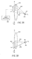
- Figs. 3A and 3B are diagrammatic views illustrating a method of the invention that allows multiple partial images to be taken with similar acquisition geometry to that obtained using screen-film systems. An overview illustration of the present invention is shown in Figs. 3A and 3B.
-
- The digital radiographic image capture device or
detector 303 can translate alongaxis 311 freely to various positions, thex-ray tube 301 does not translate but it tracks the detector movement by rotation along afixed axis 310 and always directs its exposure toward thedetector 303. First, thepatient 300 is exposed at a first position defined by the detector position A and the x-ray tube orientation T1. The collimator of thex-ray tube 301 is adjusted such that thex-rays 302 just cover thedetector 303 for imaging. Second, after thedetector 301 is translated to a second position, as indicated by B, thetube 301 rotates to a new orientation, as indicated by T2, and the aperture of the collimator is adjusted again if necessary, a second exposure of the patient is conducted. This process can be continued until the full length of the body part to be examined is imaged. There can be a slight overlap between the consecutive detector position coverage in order to facilitate image stitching byimage processor 320. In doing so, the image acquisition geometry used by the conventional screen-film is emulated. The resultant stitched composite image can achieve the equivalent image quality in terms of image appearance and geometric precision. Theoretically, the present invention requires two strict conditions (1) the x-ray tuberotational axis 310 must be perpendicular to thedetector translation axis 311, and (2)axis 310 must go through the x-ray focal spot. The second requirement guarantees that the x-ray coverage from different tube orientations is concentric, which allows the composite x-ray coverage to be similar to that used in the conventional screen-film systems. In practice, the second condition can be relaxed a little to facilitate system design. For example, the rotation axis only needs to be close to the x-ray focal spot, the impact to image quality is small as long as the distance from the focal spot to the rotation axial is far less than that from the x-ray tube to the detector. - Although the present invention has been described with respect to acquiring radiographic images of elongated body parts, it will be understood that any elongated object may be subject of the radiographic imaging techniques of the invention. Digital radiographic image capture device may be any such device but preferably is a flat panel radiographic detector known to those skilled in the art.
Claims (5)
- A method for acquiring an elongated radiographic image comprising:positioning an elongated object between a source of x-rays and a digital image capture device having a known imaging dimension which is less than a like dimension of said elongated object;moving said device in a direction parallel to said known imaging dimension to sequential contiguous positions to acquire a sequence of radiographic images of said elongated object; androtating said source of x-rays about an axis perpendicular to said direction of moving said device in coordination with said moving project said x-rays from said source toward said device.
- The method of claim 1 including adjusting the aperture of a collimator located between said source and said object so that said projected x-rays cover the device for imaging.
- The method of claim 1 wherein said source of x-rays is rotated about an axis coincident with the x-ray focal spot of said source.
- The method of claim 1 wherein aid source of x-rays is rotated about an axis the distance of which from the x-ray focal spot of said source is far less than the distance from said source of x-rays to said image capture device.
- The method of claim 1 wherein said elongated object positioned is an elongated human body part.
Applications Claiming Priority (2)
| Application Number | Priority Date | Filing Date | Title |
|---|---|---|---|
| US845588 | 1997-04-25 | ||
| US09/845,588 US20020159564A1 (en) | 2001-04-30 | 2001-04-30 | Mothod for acquiring a radiation image of a long body part using direct digital x-ray detectors |
Publications (1)
| Publication Number | Publication Date |
|---|---|
| EP1263216A1 true EP1263216A1 (en) | 2002-12-04 |
Family
ID=25295574
Family Applications (1)
| Application Number | Title | Priority Date | Filing Date |
|---|---|---|---|
| EP02076536A Withdrawn EP1263216A1 (en) | 2001-04-30 | 2002-04-18 | Method for acquiring a radiation image of a long body part using direct digital X-ray detectors |
Country Status (3)
| Country | Link |
|---|---|
| US (1) | US20020159564A1 (en) |
| EP (1) | EP1263216A1 (en) |
| JP (1) | JP2002336228A (en) |
Cited By (2)
| Publication number | Priority date | Publication date | Assignee | Title |
|---|---|---|---|---|
| DE102011089178A1 (en) * | 2011-12-20 | 2013-06-20 | Siemens Aktiengesellschaft | Method for recording e.g. three-dimensional projection image of patient with C-arm X-Ray device, involves recording partial projection images in position of radiation source, and combining partial projection images to projection image |
| US10561383B2 (en) | 2014-12-18 | 2020-02-18 | Koninklijke Philips N.V. | Imaging system for imaging an elongated region of interest of an object |
Families Citing this family (11)
| Publication number | Priority date | Publication date | Assignee | Title |
|---|---|---|---|---|
| US6944265B2 (en) * | 2002-11-25 | 2005-09-13 | Ge Medical Systems Global Technology Company, Llc | Image pasting using geometry measurement and a flat-panel detector |
| US6895076B2 (en) * | 2003-06-03 | 2005-05-17 | Ge Medical Systems Global Technology Company, Llc | Methods and apparatus for multiple image acquisition on a digital detector |
| FR2888488B1 (en) * | 2005-07-13 | 2008-10-31 | Stephanix Sa | INSTALLATION FOR RADIOGRAPHIC EXAMINATION OF LARGE DIMENSIONS |
| US7555100B2 (en) * | 2006-12-20 | 2009-06-30 | Carestream Health, Inc. | Long length imaging using digital radiography |
| WO2009149991A1 (en) * | 2008-06-09 | 2009-12-17 | Siemens Ag Österreich | Method and device for producing an overall x-ray image that is composed of partial images |
| CN101756708B (en) * | 2008-12-25 | 2012-05-23 | 株式会社东芝 | X-ray diagnostic device |
| JPWO2011043458A1 (en) * | 2009-10-09 | 2013-03-04 | 株式会社日立メディコ | Medical image processing apparatus, X-ray imaging apparatus, medical image processing program, and medical image processing method |
| EP2497424A1 (en) * | 2011-03-07 | 2012-09-12 | Agfa Healthcare | Radiographic imaging method and apparatus. |
| KR101887188B1 (en) * | 2011-11-21 | 2018-08-10 | 삼성전자주식회사 | The method and apparatus for stitching a plurality of images |
| CN104414660B (en) * | 2013-08-29 | 2017-07-28 | 深圳市蓝韵实业有限公司 | DR image obtaining and splicing method and system |
| US10702229B2 (en) | 2015-08-25 | 2020-07-07 | Samsung Electronics Co., Ltd. | X-ray imaging apparatus and method for controlling the same |
Citations (1)
| Publication number | Priority date | Publication date | Assignee | Title |
|---|---|---|---|---|
| JPH0767866A (en) * | 1993-09-06 | 1995-03-14 | Toshiba Corp | X-ray diagnostic device |
Family Cites Families (3)
| Publication number | Priority date | Publication date | Assignee | Title |
|---|---|---|---|---|
| JPH07220056A (en) * | 1993-11-26 | 1995-08-18 | Philips Electron Nv | Image composition method and image apparatus for execution of said method |
| US6233310B1 (en) * | 1999-07-12 | 2001-05-15 | General Electric Company | Exposure management and control system and method |
| US6422749B1 (en) * | 2000-07-13 | 2002-07-23 | General Electric Company | Imaging system with X-ray beam angulation compensation |
-
2001
- 2001-04-30 US US09/845,588 patent/US20020159564A1/en not_active Abandoned
-
2002
- 2002-04-18 EP EP02076536A patent/EP1263216A1/en not_active Withdrawn
- 2002-04-30 JP JP2002127874A patent/JP2002336228A/en active Pending
Patent Citations (1)
| Publication number | Priority date | Publication date | Assignee | Title |
|---|---|---|---|---|
| JPH0767866A (en) * | 1993-09-06 | 1995-03-14 | Toshiba Corp | X-ray diagnostic device |
Non-Patent Citations (1)
| Title |
|---|
| PATENT ABSTRACTS OF JAPAN vol. 1995, no. 06 31 July 1995 (1995-07-31) * |
Cited By (3)
| Publication number | Priority date | Publication date | Assignee | Title |
|---|---|---|---|---|
| DE102011089178A1 (en) * | 2011-12-20 | 2013-06-20 | Siemens Aktiengesellschaft | Method for recording e.g. three-dimensional projection image of patient with C-arm X-Ray device, involves recording partial projection images in position of radiation source, and combining partial projection images to projection image |
| DE102011089178B4 (en) * | 2011-12-20 | 2017-12-28 | Siemens Healthcare Gmbh | Method for recording a projection image and imaging device |
| US10561383B2 (en) | 2014-12-18 | 2020-02-18 | Koninklijke Philips N.V. | Imaging system for imaging an elongated region of interest of an object |
Also Published As
| Publication number | Publication date |
|---|---|
| US20020159564A1 (en) | 2002-10-31 |
| JP2002336228A (en) | 2002-11-26 |
Similar Documents
| Publication | Publication Date | Title |
|---|---|---|
| US6807250B2 (en) | Collimation device and method for acquiring a radiation image of a long body part using direct digital X-ray detectors | |
| CN101778600B (en) | Combined Nuclide-Radiographic Subject Imaging | |
| JP4354550B2 (en) | Radiation therapy planning device | |
| US6205347B1 (en) | Separate and combined multi-modality diagnostic imaging system | |
| EP1263216A1 (en) | Method for acquiring a radiation image of a long body part using direct digital X-ray detectors | |
| US7508913B2 (en) | Method or x-ray device for creating a series of recordings of medical x-ray images of a patient who might possibly be moving during the recording of the series of images | |
| EP1848985B1 (en) | Multiple mode flat panel x-ray imaging system | |
| US6487267B1 (en) | X-ray diagnostic device for producing computed tomography and radioscopic exposures | |
| WO2013005833A1 (en) | X-ray imaging device and calibration method therefor | |
| JP2003061951A (en) | Computed tomography apparatus | |
| JPH0477508B2 (en) | ||
| US6744062B2 (en) | Apparatus for radiographically imaging elongated objects | |
| JPH06181A (en) | Curved tomography equipment with plane tomography function | |
| CN101111192A (en) | X-ray tomography apparatus with variable image geometry | |
| JP2001095790A (en) | X-ray fluoroscope | |
| JP5702240B2 (en) | X-ray imaging apparatus and calibration method thereof | |
| CN106419947B (en) | System and method for tomosynthesis image acquisition | |
| US20100138044A1 (en) | System and method for fixed focus long format digital radiography | |
| JPH11318886A (en) | Panoramic radiographic system capable of x-ray ct imaging | |
| JPH0250596B2 (en) | ||
| KR102246090B1 (en) | Radiology apparatus with FOV enlargement function | |
| JPH08336520A (en) | X-ray ct system | |
| TW201906580A (en) | Contrast scanning system | |
| KR20200120108A (en) | Radiology apparatus with FOV enlargement function | |
| CN119326424B (en) | The trajectory of the C-arm in the C-arm system |
Legal Events
| Date | Code | Title | Description |
|---|---|---|---|
| PUAI | Public reference made under article 153(3) epc to a published international application that has entered the european phase |
Free format text: ORIGINAL CODE: 0009012 |
|
| AK | Designated contracting states |
Kind code of ref document: A1 Designated state(s): AT BE CH CY DE DK ES FI FR GB GR IE IT LI LU MC NL PT SE TR |
|
| AX | Request for extension of the european patent |
Free format text: AL;LT;LV;MK;RO;SI |
|
| 17P | Request for examination filed |
Effective date: 20030512 |
|
| AKX | Designation fees paid |
Designated state(s): DE FR GB |
|
| STAA | Information on the status of an ep patent application or granted ep patent |
Free format text: STATUS: THE APPLICATION HAS BEEN WITHDRAWN |
|
| 18W | Application withdrawn |
Effective date: 20040910 |