EP1263126A2 - Apparatus of controlling to rotate step motor - Google Patents
Apparatus of controlling to rotate step motor Download PDFInfo
- Publication number
- EP1263126A2 EP1263126A2 EP02253774A EP02253774A EP1263126A2 EP 1263126 A2 EP1263126 A2 EP 1263126A2 EP 02253774 A EP02253774 A EP 02253774A EP 02253774 A EP02253774 A EP 02253774A EP 1263126 A2 EP1263126 A2 EP 1263126A2
- Authority
- EP
- European Patent Office
- Prior art keywords
- detection
- step motor
- switch element
- controlling
- rotation
- Prior art date
- Legal status (The legal status is an assumption and is not a legal conclusion. Google has not performed a legal analysis and makes no representation as to the accuracy of the status listed.)
- Granted
Links
Images



Classifications
-
- H—ELECTRICITY
- H02—GENERATION; CONVERSION OR DISTRIBUTION OF ELECTRIC POWER
- H02P—CONTROL OR REGULATION OF ELECTRIC MOTORS, ELECTRIC GENERATORS OR DYNAMO-ELECTRIC CONVERTERS; CONTROLLING TRANSFORMERS, REACTORS OR CHOKE COILS
- H02P8/00—Arrangements for controlling dynamo-electric motors rotating step by step
- H02P8/02—Arrangements for controlling dynamo-electric motors rotating step by step specially adapted for single-phase or bi-pole stepper motors, e.g. watch-motors, clock-motors
-
- H—ELECTRICITY
- H02—GENERATION; CONVERSION OR DISTRIBUTION OF ELECTRIC POWER
- H02P—CONTROL OR REGULATION OF ELECTRIC MOTORS, ELECTRIC GENERATORS OR DYNAMO-ELECTRIC CONVERTERS; CONTROLLING TRANSFORMERS, REACTORS OR CHOKE COILS
- H02P8/00—Arrangements for controlling dynamo-electric motors rotating step by step
- H02P8/34—Monitoring operation
Definitions
- the present invention relates to an apparatus of controlling to rotate a step motor for driving to rotate a step motor and detecting presence or absence of rotation of the step motor.
- a step motor as a motor for driving to rotate a time hand or the like in an electronic timepiece.
- Fig. 2 is a constitution view of a step motor conventionally used in an electronic timepiece.
- a step motor is provided with a stator 401, a coil 307 wound around the stator 401 and a rotor 402 of two poles arranged at inside of the stator 401.
- the stator 401 is formed with saturable portions 403 and 404.
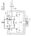
- Fig. 3 and Fig. 4 are circuit diagrams showing an apparatus of controlling to rotate a step motor conventionally used in an electronic timepiece, constituting a circuit integrally constituted with a rotation drive circuit and a rotation detection circuit.
- Fig. 3 is an explanatory view of operation when the step motor is controlled to rotate by the rotation drive circuit
- Fig. 4 is an explanatory view when rotation of the step motor is detected by the rotation detection circuit.
- Fig. 5A shows a drive pulse used in driving to rotate the step motor
- Fig. 5B shows a control pulse for detecting rotation used in detecting rotation of the step motor.
- P-channel MOS transistors 301 and 302 and N-channel MOS transistors 303 and 304 are constituent elements of a motor drive circuit and a coil 307 of a step motor is connected between a point of connecting sources of the transistor 301 and the transistor 303 and a point of connecting sources of the transistor 302 and the transistor 304.
- N-channel MOS transistors 303 through 306, a resistor 308 for detection connected in series with the transistor 305 and a resistor 309 for detection connected in series with the transistor 306 and a comparator 310 are constituent elements of the rotation detection circuit.
- Gates of the respective transistors 301 through 306 are connected in a control circuit 312.
- a point OUT2 for connecting the resistor 308 for detection and the coil 307 and a point OUT1 for connecting the resistor 309 for detection and the coil 307 are connected to an input portion of the comparator 310. Further, the input portion of the comparator 310 is inputted with threshold voltage Vss.
- a rotation detection period for detecting whether the step motor is rotated, immediately after a motor drive period.
- the input portion Vi of the control circuit 312 is supplied with rotation detection control pulse SP1 of Fig. 5B.
- the control circuit 312 controls to make the transistor 304 to ON/OFF in a state of making the transistors 303 and 306 ON.
- detection voltage is outputted from the connection point OUT1 of the resistor 309 for rotation detection and the coil 307.
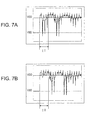
- the detection voltage there is provided a signal having a waveform as shown by Fig. 7(a).
- Fig. 7(a) there is generated detection voltage on a lower side of VDD when the rotor 42 is oscillated in the counterclockwise direction and there is generated detection voltage on an upper side of VDD when the rotor 42 is oscillated in the clockwise direction.
- the rotor 402 When the rotor 402 is rotated, there is provided detection voltage equal to or lower than predetermined threshold voltage (Vss according to the conventional example) and a rotation detection signal Vs at a high level is outputted from the comparator 310. When the rotor 402 is not rotated, the detection voltage is not equal to or lower than the threshold voltage and therefore, the rotation detection signal Vs at a low level is outputted from the comparator 310. Whether the step motor is rotated, can be detected from the rotation detection signal Vs. After detection of rotation has been finished, the transistors 303 and 304 are maintained in an ON state to thereby brake the step motor.
- Vss predetermined threshold voltage
- the following normal drive pulse P1 is supplied to the input portion Vi of the control circuit 312.
- the control circuit 312 controls the transistors 301 and 304 to an ON state and drive current in a direction reverse to that of the drive current (direction reverse to the arrow mark of Fig. 3) is made to flow at the coil 307 and the rotor 402 is rotated in the counterclockwise direction.
- the transistors 304 and 305 are controlled to ON and the transistor 303 is controlled to ON/OFF.
- detection voltage is outputted from the connection point OUT2 of the resistor 308 and the coil 307 and a level thereof is determined by the comparator 310.
- the rotation detection signal Vs at the high level is outputted from the comparator 310 and when the rotor 402 is not rotated, the rotation detection signal Vs at the low level is outputted from the comparator 310.
- the motor can be detected from the rotation detection signal Vs.
- the transistors 303 and 304 are brought into an ON state to thereby brake the step motor.
- the rotor 402 is freely oscillated centering on a position at which the rotor 402 is to be stopped.
- free oscillation of the rotor 402 is considerable, further, by inertia, the rotor 402 is oscillated in a direction the same as a regular rotational direction (counterclockwise direction in the above-described conventional example).
- current is made to flow in the arrow mark direction.
- an equivalent circuit of the respective transistors 303 through 306 is constituted by a series circuit of a switch 501 and a resistor 502 and a diode 503 and a capacitor 504 respectively connected in parallel with the series circuit and the respective transistors 303 through 306 are equivalently regarded as an element having a diode in one direction.
- the rotation is not detected during the predetermined period IT immediately after finishing the drive pulse P1 and the rotation detection operation is carried out after elapse of the period IT.
- the period IT differs by the characteristic of the step motor and therefore, the period IT needs to be set for the respective motor and there poses a problem that selection of a material, arrangement or the like of a part becomes extremely complicated.
- an apparatus of controlling to rotate a step motor characterized in that in an apparatus of controlling to rotate a step motor comprising a first and a second switch element connected in series, a third and a fourth switch element connected in series, a coil of the step motor connected between a point of connecting the first and the second switch elements and a point of connecting the third and the fourth switch elements, a first series circuit comprising a fifth switch element and a first element for detection connected in parallel with the first switch element, a second series circuit comprising a sixth switch element and a second element for detection connected in parallel with the third switch element, controlling means for driving to rotate the step motor by making a current flow to the coil by controlling the first through the fourth switches in response to a drive pulse and controlling the first, the third, the fifth and the sixth switch elements in response to a control pulse for detecting rotation supplied immediately after finishing the drive pulse, and determining means for determining presence or absence of rotation of the step motor based on a result of comparing a voltage produced between the first and the second elements
- the controlling means makes ON the fifth or the sixth element for detection on the side of producing the detection voltage in the direction reverse to the direction of the threshold voltage between the first and the second elements for detection and the coil immediately after finishing the drive pulse, controls to make ON/OFF the first switch element after bringing the third switch element to the ON state when the fifth switch element is brought into the ON state and controls to make ON/OFF the third switch element after bringing the first switch element to the ON state when the sixth switch element is brought into the ON state.
- the determining means determines presence or absence of rotation of the step motor based on the result of comparing the voltage produced between the first element for detection and the coil when the fifth switch element is brought into the ON state and determines presence or absence of the rotation of the step motor based on the result of comparing the voltage produced between the second element for detection and the coil and the threshold voltage when the sixth switch element is brought into ON state.
- first, the third, the fifth and the sixth switch elements are constituted by N-channel MOS transistors and the second and the fourth switch elements are constituted by P-channel MOS transistors.
- first and the second elements for detection may be constituted by resistors.
- Fig. 1 is a circuit diagram showing an apparatus of controlling to rotate a step motor according to an embodiment of the invention, constructing a circuit constitution integrated with a rotation drive circuit and a rotation detection circuit. Further, Fig. 1 is an explanatory view when rotation of the step motor is detected by the rotation detection circuit.
- Fig. 1 between a positive side power source terminal VDD ( ground potential) and a negative side power source terminal Vss, there are provided the series of circuit the N-channel MOS transistor 303 and the P-channel MOS transistor 301 sources of which are commonly connected and the series circuit of the N-channel MOS transistor 304 and the P-channel MOS transistor 302 sources of which are commonly connected.
- the respective series circuits are connected in parallel.
- the coil 307 of the step motor is connected between the connection point of the transistor 301 and the transistor 303 and the connection point between the transistor 302 and the transistor 304.
- a first series circuit connected in series with the N-channel MOS transistor 305 and the resistor 308 for detection
- a second series circuit connected in series with the N-channel MOS transistor 306 and the resistor 309 for detection.
- the transistor 303 constitutes a first switch element
- the transistor 301 constitutes a second switch element
- the transistor 304 constitutes a third switch element
- the transistor 302 constitutes a fourth switch element
- the transistor 305 constitutes a fifth switch element
- the transistor 306 constitutes a sixth switch element
- the resistor 308 for detection constitutes a first detection element
- the resistor 309 for detection constitutes a second detection element.
- the comparator 310 determines whether the step motor is rotated, by whether voltages produced at the connection points OUT1 and OUT2 are equal to or lower than the threshold voltage Vss. In this case, the comparator 310 constitutes determining means.
- the gates of the respective transistor 301 through 306 are connected to the control circuit 311 for controlling the transistors 301 through 306 in response to a signal inputted to the input portion Vi.
- the control circuit 311 constitutes controlling means.
- the transistors 301 through 304 are constituent elements of the motor drive circuit and transistors 303 through 306, the resistors 308 and 309 for detection, the comparator 310 and the control circuit 311 are constituent elements of the rotation detection circuit. Further, the transistor 303 and 304 and the control circuit 311 are used as constituent elements of both of the motor drive circuit and the rotation detection circuit.
- the drive pulse P1 of Fig. 5A is inputted to the input portion Vi of the control circuit 311.
- the control circuit 311 controls the transistors 302 and 303 to an ON state. Thereby, current is made to flow in the coil 307 in the arrow mark direction and as shown by Fig. 2, the rotor 402 is rotated in the counterclockwise direction.
- the rotation detection period for detecting whether the step motor is rotated, immediately after finishing the motor drive pulse period.
- the input portion Vi of the control circuit 311 is inputted with the control pulse SP1 for detecting rotation of Fig. 5B.
- the control circuit 311 controls the transistor 303 to ON/OFF in accordance with respective very small pulses constituting the control pulse SP1 for detecting rotation to thereby control to switch the transistor 303.
- the equivalent circuit of the respective transistors 303 through 306 is constituted by the series circuit of the switch 501 and the resistor 502 and the diode 503 and the capacitor 504 respectively connected in parallel with the series circuit and the respective transistors 303 through 306 are equivalently regarded as the element having the diode in one direction.
- the detection voltage is produced on the upper side of VDD, that is, in a direction reverse to the threshold voltage Vss with the predetermined voltage VDD as the reference. Further, the detection voltage is restricted to be equal to or smaller than a constant value by the equivalent diode component.
- detection voltage produced at the connection point OUT2 between the resistor 308 for detection and the coil 307 is produced on the reverse side of the threshold voltage Vss (on a side of a polarity reverse to that of the threshold voltage Vss according to the embodiment) with the predetermined voltage VDD as a reference and is restricted to a constant level by the equivalent diode.
- the comparator 310 determines presence or absence of rotation of the step motor based on a result of comparing voltage produced between the resistor 308 for detection and the coil 307, and the threshold voltage Vss. In this case, since the detection voltage becomes equal to or lower than the threshold voltage Vss, the comparator 310 determines that the step motor is rotating and outputs the rotation detection signal Vs at a high level.
- the transistors 303 and 304 are maintained in an ON state to thereby brake the step motor.
- the drive pulse P1 is newly supplied to the input portion Vi of the control circuit 311.
- the control circuit 311 controls the transistors 301 and 304 to the ON state, thereby, the drive current in a direction reverse to that of the above drive current (direction reverse to the arrow mark of Fig. 3) is made to flow in the coil 307 and the rotor 402 is rotated in the counterclockwise direction.
- the control circuit 311 controls the transistors 303 and 306 to the ON state and controls the transistor 304 to ON/OFF to thereby switch the transistor 304.
- the detection voltage is restricted and rotation or nonrotation of the step motor is detected by detection voltage produced thereafter. That is, during the rotation detection period, presence or absence of rotation is determined by comparing the detection voltage produced at the connection point OUT1 between the resistor 309 for detection and the coil 307, and the threshold voltage Vss. When the rotor 402 is rotated, the detection voltage at the connection point OUT1 becomes equal to or lower than the threshold voltage Vss and therefore, the rotation detection signal Vs at the high level is outputted from the comparator 310.
- the detection voltage at the connection point OUT1 does not become equal to or lower than the threshold voltage Vss and therefore, the rotation detection signal Vs at the low level is outputted from the comparator 310. Thereby, whether the step motor is rotated, can be detected. After detection of rotation has been finished, the transistors 303 and 304 are maintained at the ON state to thereby brake the step motor.
- the transistors 301 and 304 are driven to the ON state and during the rotation detection period, immediately after finishing the drive pulse P1, the transistors 304 and 305 are brought into the ON state and the transistor 303 is controlled to ON/OFF.
- the transistors 305 and 306 on a side in which detection voltage having a polarity reverse to that of the threshold voltage Vss is produced between the transistors 305 and 306 and the coil 307, are made ON and when the transistor 305 is brought into the ON state, the transistor 304 is brought into the ON state and the transistor 303 is controlled to ON/OFF and when the transistor 306 is brought into the ON state, the transistor 303 is brought into the ON state and the transistor 304 is controlled to ON/OFF.
- erroneous detection during the period IT can be prevented.
- an apparatus of controlling to rotate a step motor characterized in that in an apparatus of controlling to rotate a step motor comprising the transistors 303 and 301 connected in series, the transistors 304 and 302 connected in series, the coil 307 of the step motor connected between a point of connecting the transistors 303 and 301 and a point of connecting the transistors 304 and 302, a first series circuit comprising the transistor 305 and the resistor 308 for detection connected in parallel with the transistor 303, a second series circuit comprising the transistor 306 and the resistor 309 for detection connected in parallel with the transistor 304, the control circuit 312 for driving to rotate the step motor by making a current flow to the coil 307 by controlling the transistors 301 through 304 in response to the drive pulse P1 and controlling the transistors 303, 304, 305 and 306 in response to the control pulse SP1 for detecting rotation supplied immediately after finishing the drive pulse P1, and the comparator for determining presence or absence of rotation of the step motor based
- the detection voltage provided immediately after finishing the drive pulse P1 is produced in the direction reverse to the direction of the threshold voltage Vss and therefore, even in the case in which although the step motor is not rotated but the electro motive voltage of the step motor becomes high, the voltage is not detected and the concern of erroneous detection is eliminated.
- detection voltage in the case of not rotating a step motor can be restrained to be low by simple constitution. Therefore, even when there is a dispersion in a part of a motor, rotation thereof can be detected accurately.
Landscapes
- Engineering & Computer Science (AREA)
- Power Engineering (AREA)
- Control Of Stepping Motors (AREA)
- Electromechanical Clocks (AREA)
Abstract
Description
Claims (4)
- An apparatus of controlling to rotate a step motor characterized in that in an apparatus of controlling to rotate a step motor comprising a first and a second switch element connected in series, a third and a fourth switch element connected in series, a coil of the step motor connected between a point of connecting the first and the second switch elements and a point of connecting the third and the fourth switch elements , a first series circuit comprising a fifth switch element and a first element for detection connected in parallel with the first switch element, a second series circuit comprising a sixth switch element and a second element for detection connected in parallel with the third switch element, controlling means for driving to rotate the step motor by making a current flow to the coil by controlling the first through the fourth switches in response to a drive pulse and controlling the first, the third, the fifth and the sixth switch elements in response to a control pulse for detecting rotation supplied immediately after finishing the drive pulse, and determining means for determining presence or absence of rotation of the step motor based on a result of comparing a voltage produced between the first and the second elements for detection and the coil and a threshold voltage:wherein the controlling means makes ON the fifth or the sixth switch element on a side of producing a detection voltage in a direction reverse to a direction of the threshold voltage with a predetermined voltage as a reference between the first and the second elements for detection and the coil immediately after finishing the drive pulse, controls to make ON/OFF the first switch element after bringing the third switch element to an ON state when the fifth switch element is brought into the ON state and controls to make ON/OFF the third switch element after bringing the first switch element to the ON state when the sixth switch element is brought into the ON state; andwherein the determining means determines presence or absence of the rotation of the step motor based on the result of comparing the voltage produced between the first element for detection and the coil and the threshold voltage when the fifth switch element is brought into the ON state and determines presence or absence of the rotation of the step motor based on the result of comparing the voltage produced between the second element for detection and the coil and the threshold voltage when the sixth switch element is brought into the ON state.
- An apparatus of controlling to rotate a step motor according to Claim 1; wherein the first, the third, the fifth and the sixth switch elements are constituted by N-channel MOS transistors and the second and the fourth switch elements are constituted by P-channel MOS transistors.
- An apparatus of controlling to rotate a step motor according to Claim 1; wherein the first and the second elements for detection are constituted by resistors.
- An apparatus of controlling to rotate a step motor according to Claim 2; wherein the first and the second elements for detection are constituted by resistors.
Applications Claiming Priority (2)
| Application Number | Priority Date | Filing Date | Title |
|---|---|---|---|
| JP2001162924A JP4652610B2 (en) | 2001-05-30 | 2001-05-30 | Step motor rotation control device |
| JP2001162924 | 2001-05-30 |
Publications (3)
| Publication Number | Publication Date |
|---|---|
| EP1263126A2 true EP1263126A2 (en) | 2002-12-04 |
| EP1263126A3 EP1263126A3 (en) | 2003-11-12 |
| EP1263126B1 EP1263126B1 (en) | 2009-01-14 |
Family
ID=19005976
Family Applications (1)
| Application Number | Title | Priority Date | Filing Date |
|---|---|---|---|
| EP02253774A Expired - Lifetime EP1263126B1 (en) | 2001-05-30 | 2002-05-29 | Apparatus for controlling the rotation of a step motor |
Country Status (6)
| Country | Link |
|---|---|
| US (1) | US6664753B2 (en) |
| EP (1) | EP1263126B1 (en) |
| JP (1) | JP4652610B2 (en) |
| CN (1) | CN1249910C (en) |
| DE (1) | DE60230836D1 (en) |
| HK (1) | HK1052390B (en) |
Families Citing this family (6)
| Publication number | Priority date | Publication date | Assignee | Title |
|---|---|---|---|---|
| JP4236956B2 (en) * | 2003-02-24 | 2009-03-11 | セイコーインスツル株式会社 | Step motor control device and electronic timepiece |
| JP4343549B2 (en) * | 2003-02-24 | 2009-10-14 | セイコーインスツル株式会社 | Step motor control device and electronic timepiece |
| US7453230B1 (en) * | 2006-09-29 | 2008-11-18 | Cypress Semiconductor Corp. | Synchronization circuit and method of performing synchronization |
| JP5363167B2 (en) * | 2008-05-29 | 2013-12-11 | セイコーインスツル株式会社 | Stepping motor control circuit and analog electronic timepiece |
| US8111033B2 (en) * | 2008-06-17 | 2012-02-07 | Seiko Instruments Inc. | Stepping motor control circuit and analog electronic timepiece |
| JP2011203136A (en) * | 2010-03-25 | 2011-10-13 | Seiko Instruments Inc | Stepping motor control circuit and analog electronic timepiece |
Family Cites Families (10)
| Publication number | Priority date | Publication date | Assignee | Title |
|---|---|---|---|---|
| CH620062A5 (en) * | 1978-05-12 | 1980-10-31 | Portescap | |
| EP0085648B1 (en) * | 1982-01-28 | 1985-10-09 | Asulab S.A. | Stepping motor with two directions of rotation, in particular for electronic time pieces, and motor unit comprising the same |
| FR2529032A1 (en) * | 1982-06-21 | 1983-12-23 | Omega Brandt & Freres Sa Louis | PROCESS FOR SUPPLYING A STEP-BY-STEP MOTOR FOR A WATCHING PART |
| CH653850GA3 (en) * | 1983-08-12 | 1986-01-31 | ||
| JPH0681551B2 (en) * | 1984-10-16 | 1994-10-12 | セイコ−電子工業株式会社 | Rotation detection method for step motor |
| JP2762830B2 (en) * | 1992-03-19 | 1998-06-04 | 日本電気株式会社 | Stepping motor drive circuit |
| JP3724048B2 (en) * | 1995-11-06 | 2005-12-07 | 株式会社デンソー | L load drive |
| EP2512027A2 (en) * | 1998-09-10 | 2012-10-17 | Seiko Epson Corporation | Pulse motor driving device, pulse motor driving method, timepiece device, and timepiece device control method |
| US6262554B1 (en) * | 1998-09-22 | 2001-07-17 | Seiko Epson Corporation | Electronic device and method of controlling the same |
| US6861817B2 (en) * | 2001-12-21 | 2005-03-01 | Freescale Semiconductor, Inc. | Method and apparatus for detecting a stall condition in a stepping motor |
-
2001
- 2001-05-30 JP JP2001162924A patent/JP4652610B2/en not_active Expired - Lifetime
-
2002
- 2002-05-22 US US10/153,535 patent/US6664753B2/en not_active Expired - Lifetime
- 2002-05-29 DE DE60230836T patent/DE60230836D1/en not_active Expired - Lifetime
- 2002-05-29 EP EP02253774A patent/EP1263126B1/en not_active Expired - Lifetime
- 2002-05-30 CN CNB021222347A patent/CN1249910C/en not_active Expired - Fee Related
-
2003
- 2003-06-25 HK HK03104562.7A patent/HK1052390B/en not_active IP Right Cessation
Also Published As
| Publication number | Publication date |
|---|---|
| US20020180396A1 (en) | 2002-12-05 |
| US6664753B2 (en) | 2003-12-16 |
| JP2002354893A (en) | 2002-12-06 |
| CN1249910C (en) | 2006-04-05 |
| CN1388422A (en) | 2003-01-01 |
| EP1263126B1 (en) | 2009-01-14 |
| HK1052390A1 (en) | 2003-09-11 |
| EP1263126A3 (en) | 2003-11-12 |
| DE60230836D1 (en) | 2009-03-05 |
| JP4652610B2 (en) | 2011-03-16 |
| HK1052390B (en) | 2006-11-17 |
Similar Documents
| Publication | Publication Date | Title |
|---|---|---|
| JP3124473U (en) | Motor control device for brushless DC motor | |
| US7334854B1 (en) | Sensorless start-up method for driving a brushless DC motor | |
| US4740734A (en) | Control apparatus for brushless dc motors | |
| US6664753B2 (en) | Apparatus of controlling to rotate step motor | |
| CN101803173A (en) | Motor drive device | |
| US6946813B2 (en) | Step motor control device and electronic timepiece equipped with step motor control device | |
| JP4245589B2 (en) | Stator structure | |
| US4695782A (en) | System for insuring rotational direction for an alternating current motor | |
| JP4965941B2 (en) | Motor driving device, brushless motor and driving method thereof | |
| JPH0799796A (en) | Driving device for stepping motor | |
| EP0963034A1 (en) | Drive circuit with signal detection capability for a DC brushless fan motor | |
| US6914407B2 (en) | Step motor control device and electronic timepiece equipped with step motor control device | |
| JP5394658B2 (en) | Stepping motor control circuit and analog electronic timepiece | |
| JPS6161356B2 (en) | ||
| US5477411A (en) | Pulse motor control device | |
| JP2844084B2 (en) | DC motor drive circuit | |
| JP2004153906A (en) | Device for preventing reverse connection | |
| JPH07118941B2 (en) | Brushless motor coil burnout prevention device | |
| HK1070188B (en) | Step motor control device and electronic timepiece | |
| JPS6235360B2 (en) | ||
| CN114977670A (en) | motor unit | |
| JP2006067781A (en) | Brushless DC motor and its driving device | |
| HK1069441B (en) | Step motor control device and electronic timepiece | |
| JPH0530781A (en) | Controlling circuit for brushless motor | |
| KR20000009307A (en) | Rotation check circuit of sensorless bldc motor |
Legal Events
| Date | Code | Title | Description |
|---|---|---|---|
| PUAI | Public reference made under article 153(3) epc to a published international application that has entered the european phase |
Free format text: ORIGINAL CODE: 0009012 |
|
| AK | Designated contracting states |
Kind code of ref document: A2 Designated state(s): AT BE CH CY DE DK ES FI FR GB GR IE IT LI LU MC NL PT SE TR |
|
| AX | Request for extension of the european patent |
Free format text: AL;LT;LV;MK;RO;SI |
|
| PUAL | Search report despatched |
Free format text: ORIGINAL CODE: 0009013 |
|
| AK | Designated contracting states |
Kind code of ref document: A3 Designated state(s): AT BE CH CY DE DK ES FI FR GB GR IE IT LI LU MC NL PT SE TR |
|
| AX | Request for extension of the european patent |
Extension state: AL LT LV MK RO SI |
|
| RIC1 | Information provided on ipc code assigned before grant |
Ipc: 7G 04C 3/14 B Ipc: 7H 02P 8/34 B Ipc: 7H 02P 8/02 A |
|
| 17P | Request for examination filed |
Effective date: 20040506 |
|
| AKX | Designation fees paid |
Designated state(s): CH DE LI |
|
| GRAP | Despatch of communication of intention to grant a patent |
Free format text: ORIGINAL CODE: EPIDOSNIGR1 |
|
| RTI1 | Title (correction) |
Free format text: APPARATUS FOR CONTROLLING THE ROTATION OF A STEP MOTOR |
|
| GRAS | Grant fee paid |
Free format text: ORIGINAL CODE: EPIDOSNIGR3 |
|
| GRAA | (expected) grant |
Free format text: ORIGINAL CODE: 0009210 |
|
| AK | Designated contracting states |
Kind code of ref document: B1 Designated state(s): CH DE LI |
|
| REG | Reference to a national code |
Ref country code: CH Ref legal event code: EP |
|
| REG | Reference to a national code |
Ref country code: CH Ref legal event code: NV Representative=s name: PATENTANWAELTE SCHAAD, BALASS, MENZL & PARTNER AG |
|
| REF | Corresponds to: |
Ref document number: 60230836 Country of ref document: DE Date of ref document: 20090305 Kind code of ref document: P |
|
| PLBE | No opposition filed within time limit |
Free format text: ORIGINAL CODE: 0009261 |
|
| STAA | Information on the status of an ep patent application or granted ep patent |
Free format text: STATUS: NO OPPOSITION FILED WITHIN TIME LIMIT |
|
| 26N | No opposition filed |
Effective date: 20091015 |
|
| PGFP | Annual fee paid to national office [announced via postgrant information from national office to epo] |
Ref country code: CH Payment date: 20120514 Year of fee payment: 11 Ref country code: DE Payment date: 20120523 Year of fee payment: 11 |
|
| REG | Reference to a national code |
Ref country code: CH Ref legal event code: PL |
|
| PG25 | Lapsed in a contracting state [announced via postgrant information from national office to epo] |
Ref country code: LI Free format text: LAPSE BECAUSE OF NON-PAYMENT OF DUE FEES Effective date: 20130531 Ref country code: CH Free format text: LAPSE BECAUSE OF NON-PAYMENT OF DUE FEES Effective date: 20130531 Ref country code: DE Free format text: LAPSE BECAUSE OF NON-PAYMENT OF DUE FEES Effective date: 20131203 |
|
| REG | Reference to a national code |
Ref country code: DE Ref legal event code: R119 Ref document number: 60230836 Country of ref document: DE Effective date: 20131203 |