EP1263121A2 - Permanent magnet stepping motor - Google Patents
Permanent magnet stepping motor Download PDFInfo
- Publication number
- EP1263121A2 EP1263121A2 EP02011902A EP02011902A EP1263121A2 EP 1263121 A2 EP1263121 A2 EP 1263121A2 EP 02011902 A EP02011902 A EP 02011902A EP 02011902 A EP02011902 A EP 02011902A EP 1263121 A2 EP1263121 A2 EP 1263121A2
- Authority
- EP
- European Patent Office
- Prior art keywords
- pole teeth
- stator
- pitch
- width
- poles
- Prior art date
- Legal status (The legal status is an assumption and is not a legal conclusion. Google has not performed a legal analysis and makes no representation as to the accuracy of the status listed.)
- Withdrawn
Links
- 238000003491 array Methods 0.000 claims description 2
- 230000010363 phase shift Effects 0.000 abstract 1
- 239000011295 pitch Substances 0.000 description 24
- 230000003247 decreasing effect Effects 0.000 description 4
- 230000004907 flux Effects 0.000 description 4
- 238000000034 method Methods 0.000 description 4
- 230000008859 change Effects 0.000 description 3
- 229910000897 Babbitt (metal) Inorganic materials 0.000 description 2
- 230000008878 coupling Effects 0.000 description 2
- 238000010168 coupling process Methods 0.000 description 2
- 238000005859 coupling reaction Methods 0.000 description 2
- 230000006872 improvement Effects 0.000 description 2
- 230000009467 reduction Effects 0.000 description 2
- RYGMFSIKBFXOCR-UHFFFAOYSA-N Copper Chemical compound [Cu] RYGMFSIKBFXOCR-UHFFFAOYSA-N 0.000 description 1
- 229910000831 Steel Inorganic materials 0.000 description 1
- 239000000853 adhesive Substances 0.000 description 1
- 230000001070 adhesive effect Effects 0.000 description 1
- 238000005452 bending Methods 0.000 description 1
- 239000011248 coating agent Substances 0.000 description 1
- 238000000576 coating method Methods 0.000 description 1
- 238000000465 moulding Methods 0.000 description 1
- 239000002861 polymer material Substances 0.000 description 1
- 229920002635 polyurethane Polymers 0.000 description 1
- 239000004814 polyurethane Substances 0.000 description 1
- 238000004080 punching Methods 0.000 description 1
- 229910001220 stainless steel Inorganic materials 0.000 description 1
- 239000010935 stainless steel Substances 0.000 description 1
- 239000010959 steel Substances 0.000 description 1
- 238000003466 welding Methods 0.000 description 1
- 238000004804 winding Methods 0.000 description 1
Images



Classifications
-
- H—ELECTRICITY
- H02—GENERATION; CONVERSION OR DISTRIBUTION OF ELECTRIC POWER
- H02K—DYNAMO-ELECTRIC MACHINES
- H02K37/00—Motors with rotor rotating step by step and without interrupter or commutator driven by the rotor, e.g. stepping motors
- H02K37/10—Motors with rotor rotating step by step and without interrupter or commutator driven by the rotor, e.g. stepping motors of permanent magnet type
- H02K37/12—Motors with rotor rotating step by step and without interrupter or commutator driven by the rotor, e.g. stepping motors of permanent magnet type with stationary armatures and rotating magnets
- H02K37/14—Motors with rotor rotating step by step and without interrupter or commutator driven by the rotor, e.g. stepping motors of permanent magnet type with stationary armatures and rotating magnets with magnets rotating within the armatures
Definitions
- the present invention relates to the structure of a permanent magnet stepping motor (which will be called a PM stepping motor hereinafter) and, more particularly, to the pole tooth layout of a stator and the magnetic pole layout of a field rotor magnet.
- the PM stepping motor moves stepwise with vibrations owing to its basic structure, and therefore cannot meet the demands for quietness and reduction in vibrations.
- the high resolution (multi-steps) has been achieved with the improvement of control techniques such as a microstep technique.
- control techniques such as a microstep technique.
- the motor itself moves stepwise.
- the devices for this control are expensive, and cannot be used for low-cost, high-performance apparatuses which satisfy current demands.
- the pole teeth of a stator are alternately and successively excited to the north and south poles by coil energization.
- a field rotor magnet which functions as a rotor rotates about the shaft.
- the output is the integral of the magnetic poles per rotation. If the pole tooth pitch of the stator and the magnetic pole width of the field magnet coincide with each other in the circumferential direction, like in a conventional structure, the magnetic coupling is improved to supply a maximum output, but the rotation becomes more stepwise with vibrations.
- B-EMF back-electromotive force
- FFT Fast Fourier Transform
- harmonic components, particularly third harmonic components grow with respect to the fundamental wave. Suppressing the growth of the third harmonic component can make the positional change of the rotor per unit time constant. The biggest problem is how to suppress the third harmonic components.
- the present invention has been made to overcome the conventional drawbacks described above, and has for its object to provide a low-vibration, low-noise PM stepping motor with a simple structure suitable for a larger number of steps in which the rotation of a rotor is kept at a constant speed and the positional change of the rotor per step is stabilized.
- a PM stepping motor comprising: a stator assembly which is configured in a two-phase structure such that two stators, each having at its inner circumference a plurality of pole teeth in two arrays intermeshing with each other with a gap therebetween, are coupled together back to back with respective plurality of pole teeth misaligning by an electrical angle of 90 degrees; and a field rotor magnet which is arranged so as to oppose the respective plurality of pole teeth with a small air gap therebetween and which is magnetized circumferentially with a plurality of magnetic poles such that N- and S-poles, each having a predetermined width not matching a pitch of the pole teeth of each stator, are alternately disposed.
- a PM stepping motor defined in the first aspect, wherein the pitch of the pole teeth for one phase is calculated by a formula: ⁇ a one-cycle interval of magnetic poles (360°/(p/2)) ⁇ a half-cycle interval of third harmonics (360°/(p/2) x (1/6)) ⁇ /2, where p is a number of the magnetic poles with their width being constant, and wherein the pole teeth are arranged to be symmetrical about a center of the stator in such a manner that a pitch at two thereof opposing each other with respect to the center is different from the pitch at the other pole teeth than the two thereby performing pitch adjustment.
- a PM stepping motor defined in the first aspect, wherein the width of the magnetic poles for one phase is calculated by a formula: ⁇ a one-cycle interval of pole teeth (360°/(n/2)) ⁇ a half-cycle interval of third harmonics (360°/(n/2) x (1/6)) ⁇ /2, where n is a number of the poles teeth with their pitch being constant for one phase, and wherein the magnetic poles are arranged to be symmetrical about a center of the field rotor magnet in such a manner that one pair of N- and S-poles thereof opposing each other with respect to the center have a width different from the width of the other magnetic poles than the one pair, thereby performing width adjustment.
- the present invention can provide a low-vibration, low-noise PM stepping motor with a simple structure suitable for a larger number of steps that meets current demand.
- the present invention can provide a high-controllability PM stepping motor reduced in cogging, vibrations, and noise.
- the present invention can provide a high-controllability PM stepping motor with reduced cogging, vibrations, and noise.
- reference numerals 1 and 15 denote flanges each of which is obtained by punching a stainless steel plate; 2, a bearing made of a porous bearing metal; 3 and 3', stator yokes each of which is manufactured by bending a soft magnetic steel plate into a three-dimensional doughnut shape and which has pole teeth 10 and 10'; 4, bobbins each of which holds a coil; 5, coils each constituted by winding a polyurethane copper wire or the like; 6a and 6b, stators each of which sandwiches the coil 5 between the two stator yokes 3 and 3'; 7, a stator assembly formed by combining the two stators 6a and 6b back to back; 8, a shaft serving as the center of rotation; 9, a field rotor magnet which faces the pole teeth 10 and 10' and has a plurality of magnetic poles (see Figs. 5A and 5B) magnetized to a multipolar state on its external circumferential surface; and 12,
- the stator 6a is made up of the doughnut-shaped stator yokes 3 and 3' which are coupled together along the periphery.
- the stator yokes 3 and 3' are coupled together, the pole teeth 10 and 10' are intermeshed with each other with a gap therebetween.
- the bobbin 4 on which the coil 5 is wound is housed at the periphery of the stator 6a.
- the stator 6b (see Fig. 1) also has the same structure.
- the stator assembly 7 (see Fig. 1) is formed by integrating the two stators 6a and 6b back to back by a method such as molding using a polymer material.
- a rotor 22 is manufactured by fixing the sleeve 12 on the basis of the shaft 8 serving as the center of rotation in the first step, and next coating the circumferential surface of the sleeve 12 with adhesive, and last inserting the field rotor magnet 9 into the sleeve 12 so as to be coaxial with the shaft 8. Then, as shown in Figs. 5A and 5B, the circumferential surface of the field rotor magnet 9 is magnetized into a predetermined pattern along the circumferential direction.
- the pole teeth 10 and 10' of the stator assembly 7 constituted by coupling the two stators 6a and 6b together back to back are arranged around the rotor 22 such that the pole teeth 10 and 10' are intermeshed with each other with a gap therebetween along the radial direction with respect to the magnetic poles of the magnetized field rotor magnet 9.
- the bearing 2 and a bearing 16 (not shown) which are made of a porous bearing metal and respectively caulked to the flanges 1 and 15 have the shaft 8 inserted therein.
- the rotor 22 is so adjusted as to be coaxial with a circumferential direction defined by the pole teeth 10 and 10' of the stator assembly 7. Then, the flanges 1 and 15 are respectively fixed to the stators 6a and 6b by plasma welding or the like.
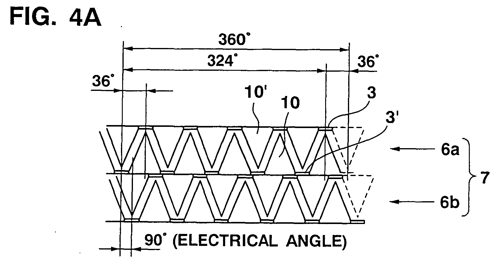
- Figs. 4A to 4C the stators 6a and 6b as the most important element of the present invention are shown with developed views.
- Fig. 4A shows the 20-step stators 6a and 6b identical to a conventional stator having a pole tooth pitch W of 36° with 20 steps.
- Fig. 4B shows the stators 6a and 6b having a pole tooth pitch W of 30°.
- Fig. 4C shows the stators 6a and 6b having a pole tooth pitch W of 42°.
- a total of ten pieces of pole teeth 10 of the stator 6a are arranged at each 36° of pitch, and each of their pitches is the same as the magnetic pole width of a conventional field rotor magnet.
- the stator 6b also has the same structure.
- the stators 6a and 6b are coupled together back to back so as to shift each of the pole teeth 10 and 10' at an electrical angle of 90°.
- the field rotor magnet 9 is divided into ten parts having an equal width in the same way as in a conventional motor, and the number P of magnetic poles is set to ten.
- the number of pole teeth 10 or 10' necessary for the stator 6a or 6b is ten pieces. Five pieces of pole teeth, which are half the total number of pole teeth of the stator 6a or 6b, are each laid out at the pole tooth pitch of 30°. An adjustment pitch between two pole teeth where the former half shifts to the latter half is set to be 60°.
- the pole tooth layout is point-symmetrical with respect to the center of the stator.
- the stator assembly 7 is constituted such that the two stators 6a and 6b with the above structure are coupled together back to back with a phase difference corresponding to an electrical angle of 90°.
- the number of pole teeth 10 or 10' necessary for the stator 6a or 6b cannot be set to be ten pieces, and therefore is set to be eight pieces.
- An adjustment pitch between two pole teeth where the former half shifts to the latter half is set to be 54°.
- the pole tooth layout is point-symmetrical with respect to the center of the stator.
- a stator assembly 7 is constituted such that the two stators 6a and 6b with the above structure are coupled together back to back with a phase difference corresponding to an electrical angle of 90°.
- the number of pole teeth 10 or 10' of the stator 6a or 6b can also be changed.
- the rotational speed can be kept unchanged with high operability.
- the pole tooth layout is shifted from the magnetic pole.
- Third harmonics contained in magnetic fluxes linked between the field magnet of the field rotor magnet 9 and the stator can sequentially cancel each other, greatly decreasing generation of third harmonics.
- the present invention can provide a high-controllability PM stepping motor reduced in cogging, vibrations, and noise.
- Figs. 5A and 5B show the magnetic pole layout of the field rotor magnet 9 in a 20-step PM stepping motor.
- Fig. 5A shows a magnetic pole layout when a calculated magnetic pole width "A" is set to be 30°.
- Fig. 5B shows a magnetic pole layout when a calculated magnetic pole width "A” is set to be 42°.
- the stators 6a and 6b have a two-phase structure in which ten pieces of pole teeth 10 and ten pieces of pole teeth 10' (see Figs. 4A and 4B) are arranged at an equal pitch and the two stators 6a and 6b are shifted by an electrical angle of 90°.
- the magnetic pole width of the field rotor magnet 9 is changed.
- the number of magnetic poles of the field rotor magnet 9 is ten, which is the same as in the conventional motor.
- the necessary number of poles is ten poles.
- Each of the first to fourth poles has the same width of 30°, and the fifth pole width is 60° as a width adjustment portion.
- Each of the sixth to ninth poles has the same width of 30° again, and finally, the 10th pole width is again 60° as a width adjustment portion.
- one pair of N- and S-poles are used as magnetic pole width adjustment portions, and the above two poles differ in width from the remaining magnetic poles.
- magnetic poles are laid out around the field rotor magnet 9 so as to be point-symmetrical with respect to the center of the field rotor magnet 9.
- all the magnetic pole widths "A" may be set to be 30°. In this case, the number of magnetic poles is twelve, and therefore the rotational speed changes.
- each of the first to fourth poles has the same width of 42°, and the fifth pole width is 12° as a width adjustment portion.
- Each of the sixth to ninth poles has the same width of 42° again, and finally, the 10th pole width is again 12° as a width adjustment portion.
- one pair of N- and S-poles are used as magnetic pole width adjustment portions, and the above two poles differ in width from the remaining magnetic poles. In this fashion, magnetic poles are laid out around the field rotor magnet 9 so as to be point-symmetrical with respect to the center of the field rotor magnet 9.
- the number of magnetic poles of the field rotor magnet 9 is the same as that of the conventional motor, but can be changed as far as the equation is satisfied.
- the rotational speed changes.
- Fig. 6 is a graph showing a comparison of the cogging torque between a stepping motor according to the present invention for 24 steps per rotation and a conventional one.
- the rotation of the stepping motor according to the present invention is smoother than that of the conventional one.
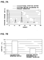
- Figs. 7A and 7B are graphs showing the cogging torque characteristics of a stepping motor according to the present invention and a conventional one.
- Fig. 7A is a graph showing a comparison of the FFT (Fast Fourier Transform) of the cogging torque
- Fig. 7B is a graph showing a comparison of the third harmonic content of the back-electromotive force.
- the harmonic component in the stepping motor according to the present invention is less than that in the conventional stepping motor.
- the component of the third harmonic involving the cogging torque is remarkably less.
- Fig. 8 is a graph showing a comparison of the angular precision (positioning precision) between a stepping motor according to the present invention and a conventional one.
- the stepping motor according to the present invention is by no means inferior to the conventional stepping motor.
- the gist of the present invention can be satisfactorily applied to an outer rotor type motor, which apparently falls within the spirit and scope of the present invention.
- the magnetic pole width of the field rotor magnet and the pole tooth pitch of the stator are so set as not to coincide with each other, and third harmonics cancel each other.
- the present invention can provide a low-vibration, low-noise, high-performance stepping motor with a simple structure suitable for a larger number of steps.
Landscapes
- Engineering & Computer Science (AREA)
- Power Engineering (AREA)
- Iron Core Of Rotating Electric Machines (AREA)
Abstract
Description
Claims (3)
- A PM stepping motor comprising:a stator assembly which is configured in a two-phase structure such that two stators, each having at its inner circumference a plurality of pole teeth in two arrays intermeshing with each other with a gap therebetween, are coupled together back to back with respective plurality of pole teeth misaligning by an electrical angle of 90 degrees; anda field rotor magnet which is arranged so as to oppose the respective plurality of pole teeth with a small air gap therebetween and which is magnetized circumferentially with a plurality of magnetic poles such that N- and S-poles, each having a predetermined width not matching a pitch of the pole teeth of each stator, are alternately disposed.
- A motor according to Claim 1,
wherein the pitch of the pole teeth for one phase is calculated by a formula:
and wherein the pole teeth are arranged to be symmetrical about a center of the stator in such a manner that a pitch at two thereof opposing each other with respect to the center is different from the pitch at the other pole teeth than the two thereby performing pitch adjustment. - A motor according to Claim 1,
wherein the pitch of the pole teeth for one phase is calculated by a formula:
Applications Claiming Priority (2)
| Application Number | Priority Date | Filing Date | Title |
|---|---|---|---|
| JP2001163924 | 2001-05-31 | ||
| JP2001163924A JP4828043B2 (en) | 2001-05-31 | 2001-05-31 | PM stepping motor |
Publications (2)
| Publication Number | Publication Date |
|---|---|
| EP1263121A2 true EP1263121A2 (en) | 2002-12-04 |
| EP1263121A3 EP1263121A3 (en) | 2005-07-13 |
Family
ID=19006805
Family Applications (1)
| Application Number | Title | Priority Date | Filing Date |
|---|---|---|---|
| EP02011902A Withdrawn EP1263121A3 (en) | 2001-05-31 | 2002-05-29 | Permanent magnet stepping motor |
Country Status (3)
| Country | Link |
|---|---|
| US (1) | US6809438B2 (en) |
| EP (1) | EP1263121A3 (en) |
| JP (1) | JP4828043B2 (en) |
Cited By (1)
| Publication number | Priority date | Publication date | Assignee | Title |
|---|---|---|---|---|
| EP1850448A1 (en) * | 2006-04-28 | 2007-10-31 | Bühler Motor GmbH | Electric motor |
Families Citing this family (17)
| Publication number | Priority date | Publication date | Assignee | Title |
|---|---|---|---|---|
| JP4062217B2 (en) * | 2003-09-01 | 2008-03-19 | 三菱電機株式会社 | Rotating electric machine |
| JP2006014583A (en) * | 2004-05-26 | 2006-01-12 | Mitsumi Electric Co Ltd | Magnetization pattern of stepping motor |
| JP4656913B2 (en) * | 2004-11-02 | 2011-03-23 | 日本電産サーボ株式会社 | Multiphase claw pole type rotating electric machine |
| US7633191B2 (en) * | 2005-04-04 | 2009-12-15 | Shinano Kenshi Kabushiki Kaisha | Multiphase step motor |
| JP2007049844A (en) * | 2005-08-11 | 2007-02-22 | Shinano Kenshi Co Ltd | Outer-rotor motor |
| JP4376863B2 (en) * | 2005-12-22 | 2009-12-02 | シナノケンシ株式会社 | Permanent magnet type rotating machine |
| JP2007221974A (en) * | 2006-02-20 | 2007-08-30 | Rohm Co Ltd | Stepping motor drive and method and electronic equipment using them |
| US7439701B2 (en) * | 2006-06-26 | 2008-10-21 | Yazaki Corporation | Method and device for detecting initial excitation phase of stepping motor |
| JP5034069B2 (en) * | 2006-12-22 | 2012-09-26 | ミネベア株式会社 | Stepping motor |
| WO2009009924A1 (en) * | 2007-07-17 | 2009-01-22 | Beijing Institute For Frontier Science | Permanent electric machine for restraining tooth torque with compensation technology |
| JP5193526B2 (en) * | 2007-08-09 | 2013-05-08 | 矢崎総業株式会社 | Stepper motor control device |
| JP5423291B2 (en) * | 2009-09-29 | 2014-02-19 | Toto株式会社 | Faucet hydroelectric generator |
| PH12012502196A1 (en) * | 2010-05-07 | 2013-02-25 | Bayer Materialscience Ag | Process for the coating of textiles |
| JP6463646B2 (en) * | 2015-02-26 | 2019-02-06 | 日本電産サンキョー株式会社 | Stepping motor |
| DE102020209303A1 (en) * | 2020-07-23 | 2022-01-27 | Brose Fahrzeugteile SE & Co. Kommanditgesellschaft, Coburg | Actuator for adjusting a vehicle assembly |
| JP2023009408A (en) * | 2021-07-07 | 2023-01-20 | 株式会社東京マイクロ | Pm-type two-phase stepping motor |
| CN118851740A (en) * | 2024-07-04 | 2024-10-29 | 湖南航天磁电科技有限公司 | A low-noise ferrite magnetic tile and its preparation method |
Citations (1)
| Publication number | Priority date | Publication date | Assignee | Title |
|---|---|---|---|---|
| JP2001169525A (en) * | 1999-09-30 | 2001-06-22 | Sanyo Denki Co Ltd | Permanent magnet type stepping motor |
Family Cites Families (33)
| Publication number | Priority date | Publication date | Assignee | Title |
|---|---|---|---|---|
| NL6807144A (en) * | 1968-05-20 | 1969-11-24 | ||
| JPS5160913A (en) * | 1974-11-25 | 1976-05-27 | Tokuzo Inaniba | |
| JPS51125814A (en) * | 1975-04-24 | 1976-11-02 | Citizen Watch Co Ltd | Printer-driving composite pulse motor |
| JPS5754636U (en) * | 1980-09-16 | 1982-03-30 | ||
| US4794292A (en) * | 1986-07-21 | 1988-12-27 | Canon Kabushiki Kaisha | Stepping motor with divided stator pole pieces |
| JPH01259748A (en) * | 1988-04-07 | 1989-10-17 | Seiko Epson Corp | stepper motor |
| JPH03143298A (en) * | 1989-10-25 | 1991-06-18 | Brother Ind Ltd | Controlling type of stepping motor |
| JP3187034B2 (en) * | 1990-03-15 | 2001-07-11 | 日本サーボ株式会社 | Stepping motor |
| EP0474048B1 (en) * | 1990-08-27 | 1995-04-05 | Canon Kabushiki Kaisha | Stepping motor and method for driving the same |
| JPH04244775A (en) * | 1991-01-31 | 1992-09-01 | Aisan Ind Co Ltd | Stepping motor |
| JP3071064B2 (en) * | 1992-04-20 | 2000-07-31 | 日本サーボ株式会社 | Permanent magnet type stepping motor |
| JPH06105526A (en) * | 1992-09-17 | 1994-04-15 | Seiko Epson Corp | PM type stepping motor |
| JPH06225509A (en) * | 1993-01-25 | 1994-08-12 | Seiko Epson Corp | PM type stepping motor |
| USRE37576E1 (en) * | 1993-02-22 | 2002-03-12 | General Electric Company | Single phase motor with positive torque parking positions |
| JPH08242572A (en) * | 1995-02-28 | 1996-09-17 | Japan Servo Co Ltd | Three-phase permanent magnet type rotary electric machine |
| JPH0923635A (en) * | 1995-07-04 | 1997-01-21 | Minebea Co Ltd | Claw-pole synchronous motor |
| US6060800A (en) * | 1995-07-12 | 2000-05-09 | Minebea Co., Ltd. | Motor structure |
| JPH1023733A (en) * | 1996-07-02 | 1998-01-23 | Sayama Precision Ind Co | Stepping motor |
| JPH1042542A (en) * | 1996-07-26 | 1998-02-13 | Nippon Seiki Co Ltd | Stepping motor |
| JP3460912B2 (en) * | 1996-10-18 | 2003-10-27 | ミネベア株式会社 | Motor structure |
| JP3458344B2 (en) * | 1997-02-03 | 2003-10-20 | ミネベア株式会社 | Motor structure |
| JP3749340B2 (en) * | 1997-03-05 | 2006-02-22 | ミネベア株式会社 | PM stepping motor |
| JP3131403B2 (en) * | 1997-04-07 | 2001-01-31 | 日本サーボ株式会社 | Stepping motor |
| US6153953A (en) * | 1997-08-05 | 2000-11-28 | Japan Servo Co., Ltd. | Multi-phase PM-type stepping motor |
| JP2000152593A (en) * | 1998-11-06 | 2000-05-30 | Mitsumi Electric Co Ltd | Stepping motor |
| JP2000224832A (en) * | 1999-01-27 | 2000-08-11 | Sanyo Denki Co Ltd | Permanent magnet type stepping motor |
| KR100292162B1 (en) * | 1999-03-17 | 2001-06-01 | 이형도 | Flat type vibration motor |
| JP3978980B2 (en) * | 1999-09-22 | 2007-09-19 | セイコーエプソン株式会社 | PM stepping motor |
| TW476180B (en) * | 1999-09-30 | 2002-02-11 | Sanyo Electric Co | Permanent magnet stepping motor |
| JP2001280247A (en) * | 2000-03-31 | 2001-10-10 | Toyota Autom Loom Works Ltd | Motor-driven compressor |
| JP4261752B2 (en) * | 2000-09-07 | 2009-04-30 | キヤノン株式会社 | Drive device |
| JP2002354775A (en) * | 2001-05-29 | 2002-12-06 | Minebea Co Ltd | Stator structure of claw pole stepping motor |
| US6891307B2 (en) * | 2002-03-29 | 2005-05-10 | Sankyo Seiki Mfg. Co., Ltd. | Motor with a plurality of pole teeth |
-
2001
- 2001-05-31 JP JP2001163924A patent/JP4828043B2/en not_active Expired - Fee Related
-
2002
- 2002-05-29 EP EP02011902A patent/EP1263121A3/en not_active Withdrawn
- 2002-05-29 US US10/159,724 patent/US6809438B2/en not_active Expired - Fee Related
Patent Citations (1)
| Publication number | Priority date | Publication date | Assignee | Title |
|---|---|---|---|---|
| JP2001169525A (en) * | 1999-09-30 | 2001-06-22 | Sanyo Denki Co Ltd | Permanent magnet type stepping motor |
Cited By (1)
| Publication number | Priority date | Publication date | Assignee | Title |
|---|---|---|---|---|
| EP1850448A1 (en) * | 2006-04-28 | 2007-10-31 | Bühler Motor GmbH | Electric motor |
Also Published As
| Publication number | Publication date |
|---|---|
| JP4828043B2 (en) | 2011-11-30 |
| US6809438B2 (en) | 2004-10-26 |
| US20020180282A1 (en) | 2002-12-05 |
| EP1263121A3 (en) | 2005-07-13 |
| JP2002359958A (en) | 2002-12-13 |
Similar Documents
| Publication | Publication Date | Title |
|---|---|---|
| US6809438B2 (en) | Permanent magnet stepping motor having pole teeth misaligned by an electrical angle | |
| WO2004107529A1 (en) | Electric motor | |
| US6900574B2 (en) | Stepping motor | |
| US6031304A (en) | Motor structure | |
| JP3364562B2 (en) | Motor structure | |
| US20090091204A1 (en) | Motor having twin-rotor | |
| JPWO2015029256A1 (en) | Synchronous motor | |
| JP7628088B2 (en) | Low noise gear motor with asymmetric electric motor | |
| EP1303030A2 (en) | Permanent magnet stepping motor | |
| US6323569B1 (en) | Stepping motor | |
| JP2008113480A (en) | motor | |
| JP3360460B2 (en) | Stepper motor | |
| JP2002112521A (en) | Rotor construction for stepping motor | |
| JP2002142432A (en) | Stepping motor | |
| JP3410519B2 (en) | Three-phase claw-pole type permanent magnet type rotating electric machine | |
| JP3591660B2 (en) | Three-phase claw pole type permanent magnet type rotating electric machine | |
| US20240186843A1 (en) | Motor | |
| JP4216369B2 (en) | Stepping motor | |
| JP2002136095A (en) | Stepping motor | |
| JP2014099996A (en) | Claw pole type stepping motor | |
| US11757340B2 (en) | Rotating electric machine | |
| JPH10136631A (en) | PM stepping motor | |
| US20220069687A1 (en) | Miniature step motor with shoeless stator and prewound bobbins | |
| EP4300774A1 (en) | Rotating electrical machine | |
| JPH0746814A (en) | Stepping motor |
Legal Events
| Date | Code | Title | Description |
|---|---|---|---|
| PUAI | Public reference made under article 153(3) epc to a published international application that has entered the european phase |
Free format text: ORIGINAL CODE: 0009012 |
|
| AK | Designated contracting states |
Kind code of ref document: A2 Designated state(s): AT BE CH CY DE DK ES FI FR GB GR IE IT LI LU MC NL PT SE TR |
|
| AX | Request for extension of the european patent |
Free format text: AL;LT;LV;MK;RO;SI |
|
| PUAL | Search report despatched |
Free format text: ORIGINAL CODE: 0009013 |
|
| AK | Designated contracting states |
Kind code of ref document: A3 Designated state(s): AT BE CH CY DE DK ES FI FR GB GR IE IT LI LU MC NL PT SE TR |
|
| AX | Request for extension of the european patent |
Extension state: AL LT LV MK RO SI |
|
| 17P | Request for examination filed |
Effective date: 20050622 |
|
| AKX | Designation fees paid |
Designated state(s): DE FR |
|
| 17Q | First examination report despatched |
Effective date: 20070417 |
|
| STAA | Information on the status of an ep patent application or granted ep patent |
Free format text: STATUS: THE APPLICATION IS DEEMED TO BE WITHDRAWN |
|
| 18D | Application deemed to be withdrawn |
Effective date: 20091201 |