EP1263107A1 - Dispositif de maintien en expansion d'un manchon élastique - Google Patents
Dispositif de maintien en expansion d'un manchon élastique Download PDFInfo
- Publication number
- EP1263107A1 EP1263107A1 EP02291275A EP02291275A EP1263107A1 EP 1263107 A1 EP1263107 A1 EP 1263107A1 EP 02291275 A EP02291275 A EP 02291275A EP 02291275 A EP02291275 A EP 02291275A EP 1263107 A1 EP1263107 A1 EP 1263107A1
- Authority
- EP
- European Patent Office
- Prior art keywords
- tubular
- film
- sleeve
- tubular element
- tubular elements
- Prior art date
- Legal status (The legal status is an assumption and is not a legal conclusion. Google has not performed a legal analysis and makes no representation as to the accuracy of the status listed.)
- Granted
Links
- 239000000463 material Substances 0.000 claims abstract description 6
- 230000001050 lubricating effect Effects 0.000 claims description 2
- 235000010599 Verbascum thapsus Nutrition 0.000 claims 1
- 244000178289 Verbascum thapsus Species 0.000 claims 1
- 125000006850 spacer group Chemical group 0.000 claims 1
- 238000000605 extraction Methods 0.000 description 7
- 210000000056 organ Anatomy 0.000 description 7
- 230000000694 effects Effects 0.000 description 5
- 239000004519 grease Substances 0.000 description 3
- 238000009434 installation Methods 0.000 description 3
- 239000000853 adhesive Substances 0.000 description 2
- 230000001070 adhesive effect Effects 0.000 description 2
- 238000006073 displacement reaction Methods 0.000 description 2
- 230000002747 voluntary effect Effects 0.000 description 2
- 238000004026 adhesive bonding Methods 0.000 description 1
- 238000005452 bending Methods 0.000 description 1
- 230000007423 decrease Effects 0.000 description 1
- 239000003292 glue Substances 0.000 description 1
- 239000000314 lubricant Substances 0.000 description 1
- 238000012423 maintenance Methods 0.000 description 1
- -1 polyethylene terephthalate Polymers 0.000 description 1
- 229920000139 polyethylene terephthalate Polymers 0.000 description 1
- 239000005020 polyethylene terephthalate Substances 0.000 description 1
- 229920001296 polysiloxane Polymers 0.000 description 1
- 230000000750 progressive effect Effects 0.000 description 1
- 230000002035 prolonged effect Effects 0.000 description 1
- QQONPFPTGQHPMA-UHFFFAOYSA-N propylene Natural products CC=C QQONPFPTGQHPMA-UHFFFAOYSA-N 0.000 description 1
- 125000004805 propylene group Chemical group [H]C([H])([H])C([H])([*:1])C([H])([H])[*:2] 0.000 description 1
- 230000000284 resting effect Effects 0.000 description 1
- 238000000926 separation method Methods 0.000 description 1
- 238000004381 surface treatment Methods 0.000 description 1
- 239000000454 talc Substances 0.000 description 1
- 229910052623 talc Inorganic materials 0.000 description 1
Images
Classifications
-
- H—ELECTRICITY
- H02—GENERATION; CONVERSION OR DISTRIBUTION OF ELECTRIC POWER
- H02G—INSTALLATION OF ELECTRIC CABLES OR LINES, OR OF COMBINED OPTICAL AND ELECTRIC CABLES OR LINES
- H02G15/00—Cable fittings
- H02G15/08—Cable junctions
- H02G15/18—Cable junctions protected by sleeves, e.g. for communication cable
- H02G15/182—Cable junctions protected by sleeves, e.g. for communication cable held in expanded condition in radial direction prior to installation
- H02G15/1826—Cable junctions protected by sleeves, e.g. for communication cable held in expanded condition in radial direction prior to installation on a removable hollow core, e.g. a tube
-
- H—ELECTRICITY
- H02—GENERATION; CONVERSION OR DISTRIBUTION OF ELECTRIC POWER
- H02G—INSTALLATION OF ELECTRIC CABLES OR LINES, OR OF COMBINED OPTICAL AND ELECTRIC CABLES OR LINES
- H02G1/00—Methods or apparatus specially adapted for installing, maintaining, repairing or dismantling electric cables or lines
- H02G1/14—Methods or apparatus specially adapted for installing, maintaining, repairing or dismantling electric cables or lines for joining or terminating cables
-
- H—ELECTRICITY
- H02—GENERATION; CONVERSION OR DISTRIBUTION OF ELECTRIC POWER
- H02G—INSTALLATION OF ELECTRIC CABLES OR LINES, OR OF COMBINED OPTICAL AND ELECTRIC CABLES OR LINES
- H02G15/00—Cable fittings
- H02G15/08—Cable junctions
- H02G15/18—Cable junctions protected by sleeves, e.g. for communication cable
- H02G15/182—Cable junctions protected by sleeves, e.g. for communication cable held in expanded condition in radial direction prior to installation
- H02G15/1826—Cable junctions protected by sleeves, e.g. for communication cable held in expanded condition in radial direction prior to installation on a removable hollow core, e.g. a tube
- H02G15/1833—Cable junctions protected by sleeves, e.g. for communication cable held in expanded condition in radial direction prior to installation on a removable hollow core, e.g. a tube formed of helically wound strip with adjacent windings, which are removable by applying a pulling force to a strip end
Definitions
- the invention relates to a device for maintaining expansion of an elastic sleeve.
- a holding device comprising a holding member arranged inside a sleeve and formed by two elements coaxial rigid conical tubulars held in position inside the sleeve by a locking member.
- the device To lay the sleeve on a cable junction or one end of the cable, the device is threaded on the cable then brought to the place of installation of the sleeve.
- the organ of interlocking securing the two tubular elements is then removed, then one of the two rigid tubular elements is extracted from the inside of the sleeve so as to apply half a sleeve on the cable.
- the other element rigid tubular is extracted to apply the other half of the sleeve on the cable.
- a layer of grease is generally interposed between the sleeve and the maintenance.
- the fat is gradually pushed back over at least part of the length of the sleeve and this then tends to adhere to rigid tubular elements supporting it.
- it is difficult to position the sleeve precisely. Indeed, the operator must hold with one hand part of the sleeve still expanded on one of the rigid tubular elements, while that it exerts traction on the other tubular element to extract it from inside the sleeve.
- the sleeve risks to be shifted by the operator during the extraction of the first rigid tubular element, and once this is removed, it is difficult to reposition the sleeve on the cable.
- An object of the invention is to propose a device for expanding the expansion of an elastic sleeve allowing positioning of the sleeve after a long period of storage.
- a device for maintaining the expansion of an elastic sleeve comprising a holding member arranged inside of the sleeve and formed by two rigid tubular elements coaxial between which is placed an organ removable tubular bracing from inside minus one of the rigid elements.
- the operator begins by removing the bracing member, which has effect of applying the central part of the sleeve which covered the bracing member on the cable part in look.
- the central part of the sleeve then grips the cable and immobilizes the sleeve on the latter, while exercising on the inner ends of the tubular elements rigid a force which tends to drive these out of the sleeve elastic. Removal of rigid tubular elements can then be carried out without risk of displacement of the sleeve.
- the tubular bracing member comprises a helical strip, one end portion of which extends to the interior of one of the rigid tubular elements and each tubular element is covered with a film folded over the interior of the corresponding tubular element and connected to tension members extending outside the sleeve elastic.
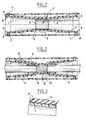
- the holding device expanding according to the invention comprises two cones 1 hollow and rigid. Cones 1 have internal ends spaced from each other and a tubular bracing member 2 is arranged between the internal ends of the cones 1.
- the bracing member 2 is here formed so known per se of a section of tube comprising perforations in a helix delimiting a strip 3, one end of which 4 extends inside tube 2 and can be pulled to extract gradually the tube from the inside by unwinding strip 3 as the remaining material enters the perforations is broken.
- the end 4 of the strip 3 forming the tube 2 further extends to the interior of one of the cones 1.
- the cones 1 and the bracing member 2 are coaxial, the conicity of the cones 1 being turned towards the bracing member 2.
- An elastic sleeve 5 is mounted in expansion on the cones 1 and the bracing member 2 which together form a member for holding the sleeve in an expanded state. How to put the elastic sleeve 5 around of the holding member is not described here, but is for example similar to that described in the document FR-2 786 954.
- a locking tube 6 is arranged around the assembly and includes at its ends orifices 7 for the reception of lugs 8 each secured to one leg flexible 9 protruding from one of the cones 1.
- the locking tube 6 ensures the stability of the device by preventing the separation of the cones 1 under the effect of the thrust of the sleeve on their outer surface.
- the assembly When installing the elastic sleeve 5 on a junction 10 between two electric cables 11, the assembly is first of all threaded onto one of the cables 11, then after completion of junction 10, the assembly is brought back above the junction. While holding the device in one hand position, the operator pulls on the end 4 of the strip 3 so as to unwind the latter and gradually remove the bracing member 2.
- the contact surface of the elastic sleeve 5 with junction 10 is limited to the central part 12 of the elastic sleeve 5, so that the friction force and tightening between the elastic sleeve 5 and the cable 10 is low enough to allow movement voluntary of the device by the operator if the latter becomes aware after removal of the organ bracing 2 that the elastic sleeve 5 is incorrectly positioned relative to junction 10.
- the locking tube still in position, the assembly is moved in block.
- a film 13 (Figure 3).
- the film 13 can for example be obtained by application of grease, or result from a treatment surface area of the cones 1.
- the material of the film 13 has a low coefficient of friction with the material of the elastic sleeve 5.
- the taper of the outer surface cones 1 combined with the presence of film 13 favors the sliding of the elastic sleeve 5 of the cones 1 during of their extraction.
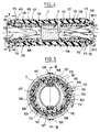
- the device according to the second embodiment of the invention comprises two rigid tubular elements 101 coaxial.
- a tubular bracing member 2 is arranged between the internal ends of the tubular elements 101.
- Each tubular element 101 comprises two half-shells 101.1 and 101.2 which are preferably secured to each other along a straight edge 103 for example by pins 104 or by an assembly in tongue and groove.
- the half-shells forming each tubular element 101 is for example molded in polyethylene terephthalate or propylene loaded with talc and are made with a rough external surface, for example by sanding the corresponding walls of the mold.
- Each tubular element 101 comprises a part before 105 of strong conicity for example whose wall forms with the axis an angle between 10 ° and 70 °, preferably 50 ° approximately, and a rear part 106 of low taper, that is to say less than 10 ° and preferably less than 1
- a film 107 covers the external surface of each tubular member 101 with slight overlap of edges longitudinal of the film (see figure 5).
- Film 107 is folded on itself along the inner edge of the tubular element 101 and is cut to form two bands 108 diametrically opposites which are each attached to a body of tension, here a hook-and-loop strap 109 connected to the ribbon 108 by a loop 110 and extending outside the sleeve 5 by resting on the outer edge 111 of the tubular element 101.
- the hook-and-loop strips 109 of a tubular element 101 are respectively connected to the corresponding bands of the other element for example in using loop bands on an element and hook bands on the opposite tubular element.
- the film 107 is fixed along its outer edge 112, for example by gluing on the tubular element or by means of a tape adhesive astride the fixing edge 112.
- a tear film is mounted adjacent to the tear edge 112.
- the tearing includes a rope 113 which is wound under the film 107 in one turn and has a cusp 114 straddling a longitudinal edge of the film 107.
- the rope 113 is also wound outside the film 107 in passing under the tension bands 109 and is slightly fixed in the vicinity of its outer end, for example by a point of glue 115.
- a primer of rupture is preferably made in the edge of the film opposite the point of cusp 114.
- An element 116 (see FIG. 5) is interposed between the rough outer surface of each tubular member 101 and the film 107 which covers it.
- This lubricating element can be obtained by a surface treatment of the film 107, at for example with a silicone grease and / or by treatment tubular element 101, or by adding a lubricant in the material constituting the tubular element 101.
- the film 107 is then released and slides along the tubular element 101 while folding along the edge internal of the tubular element under the effect of traction exerted by the tension members 109.
- the tubular element 101 is gradually ejected from the sleeve.
- the rear part weak taper extends over most the length of the tubular element so as to favor extraction of the tubular element without increasing undue clutter in the tubular element.
- the strong taper of the front part serves to give a strong component axial to the force exerted on the tubular element 101 by the retraction of the central part of the elastic sleeve 5.
- the tubular element After extraction the tubular element can be dismantled by separating the two half-shells 101.1 and 101.2. It is also possible to replace the tubular element in place over the elastic sleeve 5, preferably after inversion of each tubular element 101 so that the larger diameter parts are adjacent one to each other and coincide with the central part of the junction.
- the tubular elements thus repositioned and maintained in place by adhesive or by rings or necklaces maintained, provide mechanical protection of the elastic sleeve, in particular in the case of a cable buried on the ground.
- removable tubular bracing as being in form a strip that can be unwound
- any other type of removable tubular bracing member like a simple ring that can slide inside in one of the cones.
- tubular elements have been illustrated rigid of the holding member as being cones, the invention also applies to a device equipped of cylindrical tubular elements.
- Tension members 109 in the form of hook-and-loop strips can be replaced with elastic extending inside the tubular elements and hooked at the rear edge 111 of each tubular element. In this case it should however be noted that the tensile force decreases as the tubular element is removed.
- the number of tension members is not limited to two and can be increased if necessary to regular tension of the film 107.
Landscapes
- Cable Accessories (AREA)
- Clamps And Clips (AREA)
- Joints Allowing Movement (AREA)
- Insulating Bodies (AREA)
Abstract
Description
- la figure 1 est une vue en coupe axiale d'un manchon élastique maintenu dans un état expansé par un premier mode de réalisation du dispositif de maintien selon l'invention ;
- la figure 2 est une vue en coupe axiale analogue à celle de la figure 1 pendant la pose du manchon sur une jonction de câbles ;
- la figure 3 est une vue partielle agrandie de l'encadré A de la figure 2 ;
- la figure 4 est une vue analogue à celle de la figure 1 d'un second mode de réalisation de l'invention en coupe selon la ligne IV-IV de la figure 5 ;
- la figure 5 est une vue en coupe agrandie selon la ligne V-V de la figure 4.
Claims (11)
- Dispositif de maintien en expansion d'un manchon élastique (5), comportant un organe de maintien disposé à l'intérieur du manchon et formé par deux éléments tubulaires rigides (1 ; 101) coaxiaux, caractérisé en ce qu'un organe d'entretoisement tubulaire (2) est disposé entre les deux éléments tubulaires rigides (1 ; 101), l'organe d'entretoisement tubulaire (2) étant amovible par l'intérieur d'au moins un des éléments tubulaires rigides (1 ; 101).
- Dispositif selon la revendication 1, caractérisé en ce que l'organe d'entretoisement tubulaire (2) comporte une bande (3) en hélice dont une portion d'extrémité (4) s'étend à l'intérieur d'un des éléments tubulaires rigides (1).
- Dispositif selon la revendication 1, caractérisé en ce que les éléments tubulaires rigides (1 ; 101) ont une surface extérieure présentant une conicité tournée vers l'organe d'entretoisement tubulaire (2).
- Dispositif selon la revendication 3, caractérisé en ce que chaque élément tubulaire (101) comporte une partie avant (105) de forte conicité et une partie arrière (106) de faible conicité.
- Dispositif selon la revendication 1, caractérisé en ce que chaque élément tubulaire rigide (1 ; 101) est recouvert d'un film (13 ; 107) de matériau à faible coefficient de frottement.
- Dispositif selon la revendication 5, caractérisé en ce que le film (107) est replié à l'intérieur de l'élément tubulaire (101) correspondant et est relié à au moins un organe de tension (109).
- Dispositif selon la revendication 6, caractérisé en ce que l'organe de tension (109) s'étend de l'extérieur du manchon élastique (5).
- Dispositif selon la revendication 7, caractérisé en ce que les organes de tension (109) associés à un élément tubulaire (101) sont respectivement reliés aux organes de tension associés à l'autre élément tubulaire.
- Dispositif selon la revendication 6, caractérisé en ce que le film (107) est fixé sur l'élément tubulaire sur une face externe de celui-ci et le dispositif comporte un organe de déchirement (113) du film, adjacent à un bord de fixation (112) du film.
- Dispositif selon la revendication 1, caractérisé en ce que les éléments tubulaires (101) ont une surface externe rugueuse, et un élément lubrifiant (116) est interposé entre la surface externe des éléments tubulaires (101) et le film (107).
- Dispositif selon la revendication 1, caractérisé en ce que les éléments tubulaires (101) comportent chacun deux demi-coquilles (101.1, 101.2) séparables après mise en place du manchon élastique.
Applications Claiming Priority (2)
| Application Number | Priority Date | Filing Date | Title |
|---|---|---|---|
| FR0106978A FR2825529B1 (fr) | 2001-05-29 | 2001-05-29 | Dispositif de maintien en expansion d'un manchon elastique |
| FR0106978 | 2001-05-29 |
Publications (2)
| Publication Number | Publication Date |
|---|---|
| EP1263107A1 true EP1263107A1 (fr) | 2002-12-04 |
| EP1263107B1 EP1263107B1 (fr) | 2004-04-14 |
Family
ID=8863712
Family Applications (1)
| Application Number | Title | Priority Date | Filing Date |
|---|---|---|---|
| EP02291275A Expired - Lifetime EP1263107B1 (fr) | 2001-05-29 | 2002-05-24 | Dispositif de maintien en expansion d'un manchon élastique |
Country Status (4)
| Country | Link |
|---|---|
| EP (1) | EP1263107B1 (fr) |
| DE (1) | DE60200364T2 (fr) |
| ES (1) | ES2217242T3 (fr) |
| FR (1) | FR2825529B1 (fr) |
Cited By (5)
| Publication number | Priority date | Publication date | Assignee | Title |
|---|---|---|---|---|
| WO2006029646A3 (fr) * | 2004-09-16 | 2008-03-13 | Prysmian Cavi Sistemi Energia | Procede et dispositif d'epissage de cables electriques |
| WO2012083984A1 (fr) * | 2010-12-22 | 2012-06-28 | Prysmian S.P.A. | Ensemble de jonction pour câbles électriques |
| EP2999074A1 (fr) * | 2014-09-22 | 2016-03-23 | Societe Industrielle de Construction d'Appareils et de Materiel Electriques | Ensemble pour recouvrir à enserrement un élément allongé avec un manchon élastique de protection |
| EP3540888A1 (fr) | 2018-03-15 | 2019-09-18 | Societe Industrielle de Construction d'Appareils et de Materiel Electriques | Ensemble pour recouvrir a enserrement un element allonge avec un manchon elastique de protection |
| CN118970809A (zh) * | 2024-10-16 | 2024-11-15 | 湖南省华芯医疗器械有限公司 | 一种内窥镜电缆保护套及内窥镜 |
Citations (1)
| Publication number | Priority date | Publication date | Assignee | Title |
|---|---|---|---|---|
| FR2786954A1 (fr) * | 1998-12-02 | 2000-06-09 | Sagem | Dispositif de maintien en expansion d'un manchon elastique, et procede et dispositif de mise en expansion d'un manchon elastique |
-
2001
- 2001-05-29 FR FR0106978A patent/FR2825529B1/fr not_active Expired - Fee Related
-
2002
- 2002-05-24 ES ES02291275T patent/ES2217242T3/es not_active Expired - Lifetime
- 2002-05-24 DE DE60200364T patent/DE60200364T2/de not_active Expired - Lifetime
- 2002-05-24 EP EP02291275A patent/EP1263107B1/fr not_active Expired - Lifetime
Patent Citations (1)
| Publication number | Priority date | Publication date | Assignee | Title |
|---|---|---|---|---|
| FR2786954A1 (fr) * | 1998-12-02 | 2000-06-09 | Sagem | Dispositif de maintien en expansion d'un manchon elastique, et procede et dispositif de mise en expansion d'un manchon elastique |
Cited By (14)
| Publication number | Priority date | Publication date | Assignee | Title |
|---|---|---|---|---|
| WO2006029646A3 (fr) * | 2004-09-16 | 2008-03-13 | Prysmian Cavi Sistemi Energia | Procede et dispositif d'epissage de cables electriques |
| AU2004323329B2 (en) * | 2004-09-16 | 2009-10-01 | Prysmian Cavi E Sistemi Energia S.R.L. | Method and device for splicing electric cables |
| CN100583584C (zh) * | 2004-09-16 | 2010-01-20 | 普雷斯曼电缆及系统能源有限公司 | 编接电缆的方法和装置 |
| US7838770B2 (en) | 2004-09-16 | 2010-11-23 | Prysmian Cavi E Sistemi Energia S.R.L. | Method and device for splicing electric cables |
| WO2012083984A1 (fr) * | 2010-12-22 | 2012-06-28 | Prysmian S.P.A. | Ensemble de jonction pour câbles électriques |
| RU2557796C2 (ru) * | 2010-12-22 | 2015-07-27 | Призмиан С.П.А. | Соединительный узел для электрических кабелей |
| US9219318B2 (en) | 2010-12-22 | 2015-12-22 | Prysmian S.P.A. | Jointing assemblies for electrical cables |
| EP2999074A1 (fr) * | 2014-09-22 | 2016-03-23 | Societe Industrielle de Construction d'Appareils et de Materiel Electriques | Ensemble pour recouvrir à enserrement un élément allongé avec un manchon élastique de protection |
| FR3026240A1 (fr) * | 2014-09-22 | 2016-03-25 | App Mat Elect Const | Ensemble pour recouvrir a enserrement un element allonge avec un manchon elastique de protection |
| US10242772B2 (en) | 2014-09-22 | 2019-03-26 | Societe Industrielle De Construction D'appariels Et De Materiel Electriques | Assembly for tightly covering an elongate member with an elastic protection sleeve |
| EP3540888A1 (fr) | 2018-03-15 | 2019-09-18 | Societe Industrielle de Construction d'Appareils et de Materiel Electriques | Ensemble pour recouvrir a enserrement un element allonge avec un manchon elastique de protection |
| RU2760867C2 (ru) * | 2018-03-15 | 2021-12-01 | Сосьете Эндюстриэль Де Констрюксьон Д'Аппарей Э Де Матерьель Электрик | Устройство для плотного закрывания удлиненного элемента при помощи защитной эластичной манжеты |
| CN118970809A (zh) * | 2024-10-16 | 2024-11-15 | 湖南省华芯医疗器械有限公司 | 一种内窥镜电缆保护套及内窥镜 |
| CN118970809B (zh) * | 2024-10-16 | 2025-02-28 | 湖南省华芯医疗器械有限公司 | 一种内窥镜电缆保护套及内窥镜 |
Also Published As
| Publication number | Publication date |
|---|---|
| DE60200364T2 (de) | 2005-05-04 |
| DE60200364D1 (de) | 2004-05-19 |
| EP1263107B1 (fr) | 2004-04-14 |
| FR2825529A1 (fr) | 2002-12-06 |
| ES2217242T3 (es) | 2004-11-01 |
| FR2825529B1 (fr) | 2003-07-25 |
Similar Documents
| Publication | Publication Date | Title |
|---|---|---|
| EP0974179B1 (fr) | Dispositif de jonction de cable electrique | |
| EP0702444B1 (fr) | Support de pose d'un manchon rétractable | |
| EP0300890B1 (fr) | Liaison rapide entre deux arbres ou analogues | |
| EP0631357B1 (fr) | Support tubulaire de pose d'un manchon élastique rétractable | |
| EP2081271B1 (fr) | Ensemble pour recouvrir à enserrement un élément allongé avec un manchon élastique de protection | |
| FR2745607A1 (fr) | Dispositif d'assemblage eet de verrouillage de deux tubes, et son application pour la realisation d'une perche telescopique | |
| FR2461670A1 (fr) | Dispositif pour le serrage des tubes d'enroulement, en particulier de tubes portant des bandes de papier ou bandes de materiau analogue | |
| EP0619636B1 (fr) | Organe support pour un manchon élastique et manchon élastique maintenu dans un état expansé par un organe support amovible | |
| EP1263107B1 (fr) | Dispositif de maintien en expansion d'un manchon élastique | |
| EP0580470B1 (fr) | Applicateur pour un cathéter externe de collecte urinaire, et dispositif de collecte urinaire comportant ledit applicateur | |
| FR2975323A1 (fr) | Dispositif pour l'extraction de bague | |
| EP0940591A1 (fr) | Articulation à rotule comprenant des moyens à décrochage rapide | |
| EP1166414B1 (fr) | Dispositif support pour un manchon elastique | |
| EP3674590A1 (fr) | Dispositif pour arrimer un element sur un conduit, systeme d'arrimage, installation et procede de mise en oeuvre | |
| EP0797281B1 (fr) | Procédé et ensemble de dépose à serrage d'un revêtement tubulaire élastique sur un élément | |
| FR2910887A1 (fr) | Appareil pour derouler une bobine de film plastique enroule sur un mandrin | |
| CA2904706C (fr) | Ensemble pour recouvrir a enserrement un element allonge avec un manchon elastique de protection | |
| EP1006632A1 (fr) | Dispositif de maintien en expansion d'un manchon élastique, et procédé et dispositif de mise en expansion d'un manchon élastique | |
| EP3540888B1 (fr) | Ensemble pour recouvrir a enserrement un element allonge avec un manchon elastique de protection | |
| EP0963022B1 (fr) | Procédé et dispositif de pose d'un élément tubulaire rétractable sur un réceptacle, et assemblage ainsi obtenu | |
| CA2652684C (fr) | Ensemble pour recouvrir a enserrement un element allonge avec un manchon elastique de protection | |
| EP0669118A1 (fr) | Applicateur pour un cathéter externe de collecte urinaire et dispositif de collecte urinaire comportant ledit applicateur | |
| FR2845957A1 (fr) | Dispositif cache bagages pour coffre de vehicule automobile. | |
| FR2547247A1 (fr) | Dispositif de guidage pour la mise en place d'une roue sur l'essieu d'un vehicule automobile | |
| FR2807122A1 (fr) | Dispositif de fixation, notamment pour la fixation sur un longeron de vehicule automobile |
Legal Events
| Date | Code | Title | Description |
|---|---|---|---|
| PUAI | Public reference made under article 153(3) epc to a published international application that has entered the european phase |
Free format text: ORIGINAL CODE: 0009012 |
|
| AK | Designated contracting states |
Kind code of ref document: A1 Designated state(s): AT BE CH CY DE DK ES FI FR GB GR IE IT LI LU MC NL PT SE TR |
|
| AX | Request for extension of the european patent |
Free format text: AL;LT;LV;MK;RO;SI |
|
| 17P | Request for examination filed |
Effective date: 20030325 |
|
| AKX | Designation fees paid |
Designated state(s): DE ES GB IT |
|
| GRAP | Despatch of communication of intention to grant a patent |
Free format text: ORIGINAL CODE: EPIDOSNIGR1 |
|
| GRAS | Grant fee paid |
Free format text: ORIGINAL CODE: EPIDOSNIGR3 |
|
| GRAA | (expected) grant |
Free format text: ORIGINAL CODE: 0009210 |
|
| AK | Designated contracting states |
Kind code of ref document: B1 Designated state(s): DE ES GB IT |
|
| REG | Reference to a national code |
Ref country code: GB Ref legal event code: FG4D Free format text: NOT ENGLISH |
|
| REF | Corresponds to: |
Ref document number: 60200364 Country of ref document: DE Date of ref document: 20040519 Kind code of ref document: P |
|
| REG | Reference to a national code |
Ref country code: IE Ref legal event code: FG4D Free format text: FRENCH |
|
| GBT | Gb: translation of ep patent filed (gb section 77(6)(a)/1977) |
Effective date: 20040616 |
|
| REG | Reference to a national code |
Ref country code: ES Ref legal event code: FG2A Ref document number: 2217242 Country of ref document: ES Kind code of ref document: T3 |
|
| REG | Reference to a national code |
Ref country code: IE Ref legal event code: FD4D |
|
| PLBE | No opposition filed within time limit |
Free format text: ORIGINAL CODE: 0009261 |
|
| STAA | Information on the status of an ep patent application or granted ep patent |
Free format text: STATUS: NO OPPOSITION FILED WITHIN TIME LIMIT |
|
| 26N | No opposition filed |
Effective date: 20050117 |
|
| REG | Reference to a national code |
Ref country code: GB Ref legal event code: 732E |
|
| REG | Reference to a national code |
Ref country code: GB Ref legal event code: 732E |
|
| REG | Reference to a national code |
Ref country code: ES Ref legal event code: PC2A |
|
| REG | Reference to a national code |
Ref country code: DE Ref legal event code: R082 Ref document number: 60200364 Country of ref document: DE Representative=s name: SCHAUMBURG, THOENES, THURN, LANDSKRON, ECKERT, DE |
|
| REG | Reference to a national code |
Ref country code: DE Ref legal event code: R082 Ref document number: 60200364 Country of ref document: DE Representative=s name: PATENTANWAELTE SCHAUMBURG, THOENES, THURN, LAN, DE Effective date: 20120314 Ref country code: DE Ref legal event code: R082 Ref document number: 60200364 Country of ref document: DE Representative=s name: SCHAUMBURG & PARTNER PATENTANWAELTE GBR, DE Effective date: 20120314 Ref country code: DE Ref legal event code: R082 Ref document number: 60200364 Country of ref document: DE Representative=s name: SCHAUMBURG UND PARTNER PATENTANWAELTE MBB, DE Effective date: 20120314 Ref country code: DE Ref legal event code: R081 Ref document number: 60200364 Country of ref document: DE Owner name: SOCIETE INDUSTRIELLE DE CONSTRUCTION D'APPAREI, FR Free format text: FORMER OWNER: SILEC CABLE S.A.S., MONTEREAU FAULT YONNE, FR Effective date: 20120314 |
|
| REG | Reference to a national code |
Ref country code: GB Ref legal event code: 732E Free format text: REGISTERED BETWEEN 20120517 AND 20120523 |
|
| REG | Reference to a national code |
Ref country code: ES Ref legal event code: PC2A Owner name: SOCIETE INDUSTRIELLE DE CONSTRUCTION D APPAREILS E Effective date: 20130605 |
|
| REG | Reference to a national code |
Ref country code: DE Ref legal event code: R082 Ref document number: 60200364 Country of ref document: DE Representative=s name: SCHAUMBURG & PARTNER PATENTANWAELTE GBR, DE Ref country code: DE Ref legal event code: R082 Ref document number: 60200364 Country of ref document: DE Representative=s name: SCHAUMBURG UND PARTNER PATENTANWAELTE MBB, DE |
|
| PGFP | Annual fee paid to national office [announced via postgrant information from national office to epo] |
Ref country code: DE Payment date: 20190521 Year of fee payment: 18 Ref country code: ES Payment date: 20190620 Year of fee payment: 18 Ref country code: IT Payment date: 20190527 Year of fee payment: 18 |
|
| PGFP | Annual fee paid to national office [announced via postgrant information from national office to epo] |
Ref country code: GB Payment date: 20190521 Year of fee payment: 18 |
|
| REG | Reference to a national code |
Ref country code: DE Ref legal event code: R119 Ref document number: 60200364 Country of ref document: DE |
|
| GBPC | Gb: european patent ceased through non-payment of renewal fee |
Effective date: 20200524 |
|
| PG25 | Lapsed in a contracting state [announced via postgrant information from national office to epo] |
Ref country code: GB Free format text: LAPSE BECAUSE OF NON-PAYMENT OF DUE FEES Effective date: 20200524 |
|
| PG25 | Lapsed in a contracting state [announced via postgrant information from national office to epo] |
Ref country code: DE Free format text: LAPSE BECAUSE OF NON-PAYMENT OF DUE FEES Effective date: 20201201 |
|
| REG | Reference to a national code |
Ref country code: ES Ref legal event code: FD2A Effective date: 20211004 |
|
| PG25 | Lapsed in a contracting state [announced via postgrant information from national office to epo] |
Ref country code: IT Free format text: LAPSE BECAUSE OF NON-PAYMENT OF DUE FEES Effective date: 20200524 |
|
| PG25 | Lapsed in a contracting state [announced via postgrant information from national office to epo] |
Ref country code: ES Free format text: LAPSE BECAUSE OF NON-PAYMENT OF DUE FEES Effective date: 20200525 |