EP1263075A2 - Fuel and air supply base manifold for modular solid oxide fuels cells - Google Patents
Fuel and air supply base manifold for modular solid oxide fuels cells Download PDFInfo
- Publication number
- EP1263075A2 EP1263075A2 EP02076540A EP02076540A EP1263075A2 EP 1263075 A2 EP1263075 A2 EP 1263075A2 EP 02076540 A EP02076540 A EP 02076540A EP 02076540 A EP02076540 A EP 02076540A EP 1263075 A2 EP1263075 A2 EP 1263075A2
- Authority
- EP
- European Patent Office
- Prior art keywords
- solid oxide
- manifold
- oxidant
- fuel cell
- stack
- Prior art date
- Legal status (The legal status is an assumption and is not a legal conclusion. Google has not performed a legal analysis and makes no representation as to the accuracy of the status listed.)
- Granted
Links
Images


Classifications
-
- H—ELECTRICITY
- H01—ELECTRIC ELEMENTS
- H01M—PROCESSES OR MEANS, e.g. BATTERIES, FOR THE DIRECT CONVERSION OF CHEMICAL ENERGY INTO ELECTRICAL ENERGY
- H01M8/00—Fuel cells; Manufacture thereof
- H01M8/24—Grouping of fuel cells, e.g. stacking of fuel cells
- H01M8/249—Grouping of fuel cells, e.g. stacking of fuel cells comprising two or more groupings of fuel cells, e.g. modular assemblies
-
- H—ELECTRICITY
- H01—ELECTRIC ELEMENTS
- H01M—PROCESSES OR MEANS, e.g. BATTERIES, FOR THE DIRECT CONVERSION OF CHEMICAL ENERGY INTO ELECTRICAL ENERGY
- H01M8/00—Fuel cells; Manufacture thereof
- H01M8/24—Grouping of fuel cells, e.g. stacking of fuel cells
- H01M8/241—Grouping of fuel cells, e.g. stacking of fuel cells with solid or matrix-supported electrolytes
- H01M8/2425—High-temperature cells with solid electrolytes
- H01M8/2432—Grouping of unit cells of planar configuration
-
- H—ELECTRICITY
- H01—ELECTRIC ELEMENTS
- H01M—PROCESSES OR MEANS, e.g. BATTERIES, FOR THE DIRECT CONVERSION OF CHEMICAL ENERGY INTO ELECTRICAL ENERGY
- H01M8/00—Fuel cells; Manufacture thereof
- H01M8/24—Grouping of fuel cells, e.g. stacking of fuel cells
- H01M8/2465—Details of groupings of fuel cells
- H01M8/2483—Details of groupings of fuel cells characterised by internal manifolds
-
- H—ELECTRICITY
- H01—ELECTRIC ELEMENTS
- H01M—PROCESSES OR MEANS, e.g. BATTERIES, FOR THE DIRECT CONVERSION OF CHEMICAL ENERGY INTO ELECTRICAL ENERGY
- H01M8/00—Fuel cells; Manufacture thereof
- H01M8/24—Grouping of fuel cells, e.g. stacking of fuel cells
- H01M8/2465—Details of groupings of fuel cells
- H01M8/2484—Details of groupings of fuel cells characterised by external manifolds
- H01M8/2485—Arrangements for sealing external manifolds; Arrangements for mounting external manifolds around a stack
-
- Y—GENERAL TAGGING OF NEW TECHNOLOGICAL DEVELOPMENTS; GENERAL TAGGING OF CROSS-SECTIONAL TECHNOLOGIES SPANNING OVER SEVERAL SECTIONS OF THE IPC; TECHNICAL SUBJECTS COVERED BY FORMER USPC CROSS-REFERENCE ART COLLECTIONS [XRACs] AND DIGESTS
- Y02—TECHNOLOGIES OR APPLICATIONS FOR MITIGATION OR ADAPTATION AGAINST CLIMATE CHANGE
- Y02E—REDUCTION OF GREENHOUSE GAS [GHG] EMISSIONS, RELATED TO ENERGY GENERATION, TRANSMISSION OR DISTRIBUTION
- Y02E60/00—Enabling technologies; Technologies with a potential or indirect contribution to GHG emissions mitigation
- Y02E60/30—Hydrogen technology
- Y02E60/50—Fuel cells
Definitions
- a fuel cell is an energy conversion device that generates electricity and heat by electrochemically combining a gaseous fuel, such as hydrogen, carbon monoxide, or a hydrocarbon, and an oxidant, such as air or oxygen, across an ion-conducting electrolyte.
- the fuel cell converts chemical energy into electrical energy, which may then be used by a high-efficiency electric motor, or stored.
- SOFCs are currently constructed of solid-state materials, typically utilizing an ion conductive oxide ceramic as the electrolyte.
- a conventional electrochemical cell in a SOFC is comprised of an anode and a cathode with an electrolyte disposed therebetween.
- the oxidant passes over the oxygen electrode or cathode while the fuel passes over the fuel electrode or anode, generating electricity, water, and heat.
- a fuel flows to the anode where it is oxidized by oxygen ions from the electrolyte, producing electrons that are released to the external circuit, and mostly water and carbon dioxide are removed in the fuel flow stream.
- the oxidant accepts electrons from the external circuit to form oxygen ions.
- the oxygen ions migrate across the electrolyte to the anode.
- the flow of electrons through the external circuit provides for consumable or storable electricity.
- each individual electrochemical cell generates a relatively small voltage. Higher voltages may be attained by electrically connecting a plurality of electrochemical cells in series to form a stack.
- a SOFC cell stack also includes conduits to allow passage of the fuel and oxidant into, and byproducts as well as excess fuel and oxidant out of the stack.
- oxidant is fed to the structure from a manifold located on one side of the stack, while fuel is provided from a manifold located on an adjacent side of the stack.
- the fuel and oxidant are generally pumped through the manifolds and introduced to a flow field disposed adjacent to the appropriate electrode.
- the flow fields that direct the fuel and oxidant to the respective electrodes typically create oxidant and fuel flows that are perpendicular to one another across the electrodes.
- Seals are provided around the edges of the various cell stack components to inhibit crossover of fuel and/or oxidant.
- seals are disposed between the electrodes and adjacent flow fields, around manifolds, between flow fields and cell separators, and elsewhere.
- a fuel and air supply base manifold for a modular solid oxide fuel cell assembly having a plurality of receiving areas for receiving a plurality of solid oxide fuel cell stacks; a fuel inlet passageway disposed between a manifold fuel inlet port and a plurality of stack fuel inlet ports; an oxidant inlet passageway disposed between a manifold oxidant inlet port and a plurality of stack oxidant inlet ports; a fuel outlet passageway disposed between a plurality of stack fuel outlet ports and a manifold fuel outlet port; and an oxidant outlet passageway disposed between a plurality of stack oxidant outlet ports and a manifold oxidant outlet port.
- a method for using a base manifold for a modular solid oxide fuel cell assembly comprising receiving a plurality of solid oxide fuel cell stacks relative to the base manifold; distributing fuel to the plurality of solid oxide fuel cell stacks through the manifold; distributing oxidant to the plurality of solid oxide fuel cell stacks through the manifold; collecting fuel stream flow from the plurality of solid oxide fuel cell stacks through the manifold; and collecting oxidant stream flow from the plurality of solid oxide fuel cell stacks through the manifold.
- SOFC solid oxide fuel cell
- the system may comprise at least one SOFC assembly, one or more heat exchangers, one or more compressors, an exhaust turbine, a catalytic converter, phase change material, desulfurizer, fuel reformer, burner, preheating device, plasmatron, thermal storage system, electrical source (e.g., battery, capacitor, motor/generator, turbine, and the like, as well as combinations comprising at least one of the foregoing electrical sources), and conventional connections, wiring, control valves, and a multiplicity of electrical loads, including, but not limited to, lights, resistive heaters, blowers, air conditioning compressors, starter motors, traction motors, computer systems, radio/stereo systems, and a multiplicity of sensors and actuators, and the like, as well as combinations comprising at least one of the foregoing equipments.
- electrical source e.g., battery, capacitor, motor/generator, turbine, and the like, as well as combinations comprising at least one of the foregoing electrical sources
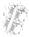
- an exemplary configuration of a modular SOFC assembly is indicated generally by the reference numeral 10.
- the assembly 10 includes four stacks 12 connected to two sides of a gas distribution manifold 16.
- Each stack comprises a plurality of electrochemical cells 14, such as SOFCs, sandwiched together along their planar surfaces, and located between a stack cap 13 and a stack footprint 15.
- Each stack footprint 15 is mechanically disposed to, but electrically insulated from the gas distribution manifold 16, for mounting the stacks 12 to the manifold 16.
- An alternate embodiment may have the footprints 15 electrically disposed to the manifold 16.
- Each stack 12 is electrically conductive, and has a top terminal 26 (only one shown) electrically connected to its cap 13, and a bottom terminal 28 (only one shown) electrically connected to its footprint 15.
- the assembly 10 further includes a port assembly 18 for introducing cathode air and anode fuel to the assembly 10.
- each stack 12 is individually configurable to include any desired number of individual cells 14, and the exemplary manifold 16 supports up to four such stacks 12, each having any desired number of individual cells 14.
- the exemplary manifold 16 is shown to be rectilinear, it shall be understood by those of ordinary skill in the pertinent art that various other geometries may be employed, such as, for example, a non-linear manifold 16 in which the stacks 12 on one side of the manifold 16 are disposed at an angle of greater than 180 degrees to one another while the stacks on the other side of the manifold are disposed at an angle of less than 180 degrees to one another.
- cross-sectional geometry which is shown as rectangular, can be any geometry, including rounded, multisided, and the like, such as square, oblong, circular, hexagonal, and the like.
- a square cross-sectional geometry manifold could be employed with one cell stack disposed each of two opposite sides of the manifold.
- each cell stack 12 may comprise the same or a different number of cells as any of the other cell stacks, and that further design options are enabled by varying the number of cells in the respective stacks.
- the electrochemical cell 14 comprises a fuel electrode or anode 30 and an oxygen electrode or cathode 50 disposed on opposite sides of a solid electrolyte 40.
- Two interconnects (or current collectors) 20 are disposed adjacent to the electrochemical cell 14.
- a second anode 30 is disposed adjacent to interconnect 20 to illustrate the placement of and ability to stack several electrochemical cells electrically connected to electrochemical cell 14.
- the passageways 22 carry fuel to the anodes 30 from a fuel inlet port at the port assembly 18 of Figure 1.
- Passageway 24 carries oxygen to the cathode 50, which is thereby disposed in fluid communication to an air inlet port at the port assembly 18.
- the solid electrolyte 40 of the electrochemical cell 14 can be an ion conductor that is capable of transporting oxygen ions from the cathode 50 to the anode 30, and that is compatible with the environment in which the SOFC will be utilized (e.g., temperatures of about -40°C up to about 1,000°C).
- solid electrolyte materials include conventional materials, such as ceramics or metals (e.g., alloys, oxides, gallates, and the like), including zirconium, yttrium, calcium, magnesium, aluminum, rare earths, and the like, as well as oxides, gallates, aluminates, combinations, and composites comprising at least one of the foregoing materials.
- the electrolyte is a rare earth oxide (such as yttria, gadolinia, neodymia, ytterbia, erbia, ceria, and the like, as well as combinations comprising at least one of the foregoing oxides) doped with aliovalient oxide(s) (such as magnesia, calcia, strontia, and the like, and other + 2 valence metal oxides).
- rare earth oxide such as yttria, gadolinia, neodymia, ytterbia, erbia, ceria, and the like, as well as combinations comprising at least one of the foregoing oxides
- aliovalient oxide(s) such as magnesia, calcia, strontia, and the like, and other + 2 valence metal oxides.
- the anode 30 and cathode 50 which form phase boundaries (gas/electrolyte/catalyst particle; commonly known as triple points) with the electrolyte 40, can be disposed adjacent to or integral with the electrolyte 40.
- the anode 30 and cathode 50 are generally formed of a porous material capable of functioning as an electrical conductor and capable of facilitating the appropriate reactions.
- the porosity of these materials should be sufficient to enable dual directional flow of gases (e.g., to admit the fuel or oxidant gases and permit exit of the byproduct gases), with a porosity of about 20% to about 40% typically preferred.
- the composition of the anode 30 and cathode 50 can comprise elements such as zirconium, yttrium, nickel, manganese, strontium, lanthanum, perovskite, and the like, as well as oxides, alloys, and combinations comprising at least one of the foregoing or comparable elements.
- the anode material is formed upon a ceramic skeleton, such as yttria-stabilized zirconica, for thermal compatibility.
- One preferred type of anode is an anode support, wherein the electrolyte is formed on the anode support.
- Either or both of the anode 30 and the cathode 50 can be formed on the electrolyte 40 by a variety of techniques including sputtering, chemical vapor deposition, screen printing, spraying, dipping, painting, and stenciling, among others.
- the electrodes are disposed typically up to about 1,000 microns or so in thickness.
- the electrochemical cell 14 can be electrically connected with other electrochemical cells by using interconnects 20.
- the fuel and the oxidant flow through the electrochemical cell 14 via the passageways 22 and 24 of the interconnects 20.
- the interconnects 20 are generally formed of a material capable of withstanding the pressures and temperatures of the SOFC, and capable of conducting electricity.
- suitable interconnects can be in the form of non-integral conductive wool, felt, or fibrous mat, formed metals, conductive ceramics, and the like; which are capable of withstanding automobile operating conditions (e.g., temperatures of about -40°C to about 1,000°C); and are electrically conductive material that is compatible with the oxidizing or reducing nature of the fuel cell environment.
- Some possible interconnects can comprise materials such as silver, copper, ferrous materials, strontium, lanthanum, chromium, chrome, gold, platinum, palladium, nickel, titanium, conducting ceramics (e.g., doped rare earth oxides of chromium, manganese, cobalt, nickel, and the like; doped zirconia, including, zirconia doped with titanium, copper, and the like), and the like, as well as alloys, oxides, cermets, composites, and combinations comprising at least one of the foregoing materials.
- Each individual electrochemical cell 14 comprising a single anode 30, a single electrolyte 40, and a single cathode 50, generates a relatively small voltage, generally in the neighborhood of about 0.6 to about 1.1 volts. Higher voltages are attained by electrically connecting a plurality of electrochemical cells in series to form a stack.
- the total number of cells forming a stack can range from 2 to several hundred, depending on power requirements, space and weight restrictions, economics, and the like.
- the electrochemical cell 14 produces an electron flow as illustrated by electron flow arrow 60.
- the electrical current flow typically measured in amperes, is opposite to the direction of negatively charged electron flow.
- Oxidant gases such as oxygen or air, can be introduced to the cathode side of the cell, flowing as illustrated by the oxidant flow arrow 64.
- the oxidant receives the flowing electrons (e - ) and converts them into oxygen ions (O -2 ), which diffuse through the electrolyte 40 to the anode 30, as described in the following reaction: O 2 + 4 e - ⁇ 2 O - 2
- the oxygen ions react with a fuel, such as hydrogen, carbon monoxide, methane, reformate, or other hydrocarbon compound, which was introduced to the electrochemical cell 14 of Figure 2 as illustrated by the fuel flow arrow 62.
- Reformate may comprise fuel as well as byproducts, such as, for example, H 2 , CO, HC, H 2 O, and N 2 .
- the reaction of the fuel and oxygen ions produces electrons (e - ), which flow outside of the electrochemical cell 14 to the external circuit 70 and back to the cathode 50.
- the electrolyte 40 conducts these oxygen ions (O -2 ) between the anode 30 and the cathode 50, maintaining an overall electrical charge balance.
- the cycle of flowing electrons (e - ) from the anode 30 through the external circuit 70 to the cathode 50 creates useable electrical energy.
- This electrical energy or electricity is produced by the ionization of the oxygen and can be directly utilized by the vehicle to power various electrical parts, including, but not limited to, lights, resistive heaters, blowers, air conditioning compressors, starter motors, traction motors, computer systems, radio/stereo systems, and a multiplicity of sensors and actuators, among others.
- each cell stack 12 may be electrically disposed in series with another, in parallel with another, in one of various series/parallel hybrid combinations with the others, or electrically undisposed from the other cell stacks 12.
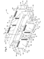
- Figure 4 illustrates the gas distribution manifold 16 of Figure 1 in greater detail.
- the manifold 16 is designed to receive a plurality of cell stacks 12 of Figure 1, physically arranged in parallel, with cells 14 of Figure 1 of an individual stack physically arranged in series.
- the manifold 16 comprises first and second side plates 82, 84, respectively, with a center housing 80 disposed therebetween.
- the port assembly 18 of Figure 1 mounts to the first side plate 82, and the stacks 12 of Figure 1 mount to the outer surfaces of the first and second side plates 82 and 84.
- the center housing 80 has a plurality of cavities that form passageways providing fluid communication between the port assembly 18 of Figure 1 and the stacks 12 of Figure 1.
- the first side plate 82 has an air inlet port 86 and stack air inlet ports 88 disposed in fluid communication.
- the center housing 80 forms a first passageway 87 to route the air from the air inlet port 86 to the stack air inlet ports 88.
- the stack air inlet ports 88 optionally include flow straighteners in this exemplary embodiment.
- An air stream flow returns from the stacks at stack air return ports 90.
- the center housing 80 forms a second passageway 91 to collect the air stream flow from the air return ports 90 and direct the collected air stream flow to an air outlet port 92.
- the stack air inlet ports 88 which optionally comprise flow straighteners, are in fluid communication with air outlet port 92 via the cell stack 12 and air return ports 90.
- the flow straighteners may comprise a plurality of elongated channels or like shapes to for serve the function of reducing turbulence relative to the inlet ports 88.
- the first side plate 82 also has an oxidant fuel inlet port 94 and stack fuel inlet ports 96.
- the center housing 80 forms a third passageway 95 to route the fuel from fuel inlet port 94 to the stack fuel inlet ports 96.
- the stack fuel inlet ports 96 optionally include flow straighteners in this exemplary embodiment.
- Fuel stream flows return from the stacks at stack fuel return ports 98.
- the center housing 80 forms two fourth passageways 99 to collect the fuel stream flows from the fuel return ports 98 and direct the collected fuel stream flows to the fuel stream outlet ports 100.
- the first side plate 82 comprises a fuel inlet port 94 that is in fluid communication with cell stack inlet ports 96 via fuel passageway 95 of center housing 80; and the stack fuel inlet ports 96, which optionally comprise flow straighteners, are in fluid communication with fuel outlet ports 100 via the cell stacks 12 and the cell stack fuel return ports 98.
- the flow straighteners may also function as filters to help prevent debris from reaching or damaging the cells 14.
- a filter may be disposed at the manifold inlet port.
- the second side plate 84 is similar to the first side plate 82 in that it includes stack ports 88, 90, 96, and 98 each disposed in fluid communication with the corresponding stack port of the first side plate 82 via the housing passageways 87, 91, 95, and 99, respectively.
- the second side plate 84 does not include ports 86, 92, 94, and 100 in this exemplary embodiment, although any such ports are optional in an alternate embodiment.
- the side plates 82 and 84 include alignment holes 106 to facilitate an accurate alignment with the center housing 80 during assembly, and stack mounting holes 108 for receiving stack-mounting hardware.
- the housing 80 further includes eight chambers 102 and four chambers 104.
- the chambers 102 and 104 can be dead air space for helping to insulate the manifold from an outside environment.
- at least one of the chambers 102 and 104 may optionally contain heat-conducting media in order to transfer heat from at least one surface to at least one other surface, such as, for example, from at least one of the outflow passageways 91 and 99 to at least one of the inflow passageways 87 and 95.
- the manifold 16 is preferably designed to substantially simultaneously introduce fuel and air to the stacks 12 connected to the manifold 16 through passageways 95 and 87 leading to ports 96 and 88, respectively.
- the fuel and air is catalyzed to produce free electrons and byproducts.
- the energy produced by the flow of free electrons is harnessed by an external circuit, which may electrically interconnect the stacks in series to produce higher output voltages, or in parallel to produce higher output currents.
- Each stack footprint 15 is configured in the same manner as each other stack footprint 15 so that the stacks 12 are interchangeable. This is possible because the stack inlet and outlet ports are defined by their connection with the air and fuel manifold ports 88, 90 and 96, 98, respectively. One or both of the direction of air flow and the direction of fuel flow through each cell stack is arbitrary.
- FIG 5 illustrates experimentally obtained stack-to-stack electrical voltage distribution data indicative of the stack-to-stack voltage output for a given current flow through the SOFC assembly 10 of Figure 1.
- the relative voltage output level of each stack 12 of Figure 1 remains substantially balanced with the other stacks for elevated levels of electrical current through each stack, respectively.
- the substantial similarity of the voltages V1, V2, V3 and V4 indicates that the base manifold 16 provides air and fuel flow distributions from the base manifold 16 to the stacks 12 that are substantially uniform for each stack 12.
- the SOFC can be operated at high adiabatic temperatures, such as up to about 1,000°C, subject to catalyst limitations. Operating temperatures of about 600°C to about 900°C, and preferably about 650°C to about 800°C, are typically employed. Consequently, at least one heat exchanger is preferably employed to cool the SOFC effluent and conversely heat the air prior to entering the SOFC, with conventional heat exchangers generally employed.
- the fuel utilized in the system is typically chosen based upon the application, and the expense, availability, and environmental issues relating to the fuel.
- Possible fuels include conventional fuels such as hydrocarbon fuels, including, but not limited to, conventional liquid fuels, such as gasoline, diesel, ethanol, methanol, kerosene, and others; conventional gaseous fuels, such as natural gas, propane, butane, and others; and alternative or “new" fuels, such as hydrogen, biofuels, Fischer Tropch, dimethyl ether, and others; and synthetic fuels, such as synthetic fuels produced from methane, methanol, coal gasification or natural gas conversion to liquids, combinations comprising at least one of the foregoing methods, and the like; and combinations comprising at least one of the foregoing fuels.
- the preferred fuel is typically based upon the type of engine employed, with lighter fuels, i.e., those which can be more readily vaporized and/or conventional fuels which are readily available to consumers, generally preferred.
- a modular SOFC assembly as disclosed herein is that the modular configuration permits the total number of cells to be easily adjusted to meet specific electrical design criteria, such as, for example, a particular voltage or current output range. Further the stack-to-stack voltage distribution and corresponding stack-to-stack power distribution can be balanced and maintains a minimal variance for increasing current loads. In other words, a uniform flow distribution for each stack assures that one stack will not run short of air or fuel at an appreciably lower power output level than that of the other stacks.
- the modular configuration permits the arrangement of the cells to be easily adjusted to meet specific physical design criteria, such as, for example, a particular packaging arrangement.
- specific physical design criteria such as, for example, a particular packaging arrangement.
- the ability to adjust the physical design of the system simplifies placement of the SOFC assembly in a vehicle.
- the modules can be serviced or replaced individually, and therefore more easily than disassembling a fuller stack in a single-stack SOFC assembly.
- Yet another advantage of employing the modular assembly is that the flow management is simplified by utilizing shorter flow paths allowed by shorter stacks than possible with the longer flow paths required for a single taller stack, thus reducing external plumbing and routing complexity. Meanwhile, an advantage of the SOFC manifold is that the flow straighteners contribute to uniform air and fuel flow distributions for each stack. While preferred embodiments have been shown and described, various modifications and substitutions may be made thereto without departing from the spirit and scope of this disclosure. Accordingly, it is to be understood that the present disclosure has been described by way of illustration only, and such illustrations and embodiments as have been disclosed herein are not to be construed as limiting to the claims.
Landscapes
- Life Sciences & Earth Sciences (AREA)
- Engineering & Computer Science (AREA)
- Manufacturing & Machinery (AREA)
- Sustainable Development (AREA)
- Sustainable Energy (AREA)
- Chemical & Material Sciences (AREA)
- Chemical Kinetics & Catalysis (AREA)
- Electrochemistry (AREA)
- General Chemical & Material Sciences (AREA)
- Fuel Cell (AREA)
Abstract
Description
Unreacted fuel and byproducts, such as water or carbon monoxide, exit the
Claims (23)
- A base manifold (16) for a modular solid oxide fuel cell assembly (10), comprising:a plurality of receiving areas for receiving a plurality of solid oxide fuel cell stacks (12);a fuel inlet passageway (95) disposed between a manifold fuel inlet port (94) and a plurality of stack fuel inlet ports (96);an oxidant inlet passageway (87) disposed between a manifold oxidant inlet port (86) and a plurality of stack oxidant inlet ports (88);a fuel outlet passageway (99) disposed between a plurality of stack fuel outlet ports (98) and a manifold fuel outlet port (100); andan oxidant outlet passageway (91) disposed between a plurality of stack oxidant outlet ports (90) and a manifold oxidant outlet port (92).
- The base manifold of Claim 1, wherein the base manifold (16) is substantially rectilinear.
- The base manifold of Claim 1, wherein the fuel inlet (95) and fuel outlet (99) passageways are disposed on opposite sides of a solid oxide fuel cell stack (12).
- The base manifold of Claim 1, wherein the oxidant inlet (87) and oxidant outlet (91) passageways are disposed on opposite sides of a solid oxide fuel cell stack (12).
- The base manifold of Claim 1, wherein the plurality of receiving areas (15) are substantially interchangeable for receiving a solid oxide fuel cell stack (12) having a given footprint.
- The base manifold of Claim 1, wherein at least two of the plurality of receiving areas (15) are disposed on one side of the base manifold (16).
- The base manifold of Claim 1, wherein at least two of the plurality of receiving areas (15) are disposed on opposite sides of the base manifold (16).
- The base manifold of Claim 1, wherein at least one of the fuel inlet passageway (95) and the oxidant inlet passageway (87) comprises a filter.
- The base manifold of Claim 1, further comprising at least one insulating chamber (102, 104).
- The base manifold of Claim 1, further comprising at least one port assembly (86, 88, 94, 96) for admitting at least one of fuel and oxidant to the base manifold (16).
- The base manifold of Claim 1, further comprising:a center housing (80);a first side plate (82) disposed to a first side of the base manifold (16); anda second side plate (84) disposed to a second side of the base manifold (16).
- The base manifold of Claim 11, wherein each of the passageways (87, 91, 95, 99) comprise a cavity in the center housing selectively aligned with at least one port (86, 88, 94, 96) in at least one of the first and second side plates (82, 84).
- A modular solid oxide fuel cell assembly (10) comprising:a base manifold (16); anda plurality of cell stacks (12) disposed to the base manifold (16), wherein each cell stack (12) comprises at least one solid oxide fuel cell (14).
- The solid oxide fuel cell assembly of Claim 13, wherein the base manifold (16) comprises:a plurality of receiving areas (15) for receiving a plurality of solid oxide fuel cell stacks (12);a fuel inlet passageway (95) disposed between a manifold fuel inlet port (94) and a plurality of stack fuel inlet ports (96);an oxidant inlet passageway (87) disposed between a manifold oxidant inlet port (86) and a plurality of stack oxidant inlet ports (88);a fuel outlet passageway (99) disposed between a plurality of stack fuel outlet ports (98) and a manifold fuel outlet port (100); andan oxidant outlet passageway (91) disposed between a plurality of stack oxidant outlet ports (90) and a manifold oxidant outlet port (92).
- The solid oxide fuel cell assembly of Claim 13, wherein each cell stack (12) comprises the same number of cells (14) as each other cell stack (12).
- The solid oxide fuel cell assembly of Claim 13, wherein the cell stacks (12) are disposed electrically in series.
- The solid oxide fuel cell assembly of Claim 13, wherein the cell stacks (12) are disposed electrically in parallel.
- The solid oxide fuel cell assembly of Claim 13, wherein the cell stacks (12) are disposed electrically in a series/parallel hybrid combination.
- A base manifold (16) for a modular solid oxide fuel cell assembly (10), comprising:means for receiving a plurality of solid oxide fuel cell stacks;means for distributing fuel to the plurality of solid oxide fuel cell stacks;means for distributing oxidant to the plurality of solid oxide fuel cell stacks;means for collecting fuel stream flow from the plurality of solid oxide fuel cell stacks; andmeans for collecting oxidant stream flow from the plurality of solid oxide fuel cell stacks.
- The base manifold of Claim 19, wherein at least two of said means for receiving are disposed on opposite sides of the base manifold (16).
- A method for using a base manifold (16) for a modular solid oxide fuel cell assembly (10), comprising:distributing fuel to a plurality of solid oxide fuel cell stacks (12) through a base manifold (16);distributing oxidant to the plurality of solid oxide fuel cell stacks (12) through the base manifold (16);collecting fuel stream flow from the plurality of solid oxide fuel cell stacks (12) through the base manifold (16); andcollecting oxidant stream flow from the plurality of solid oxide fuel cell stacks (12) through the base manifold (16).
- The method as defined in Claim 21, further comprising:flowing substantially uniform rates of fuel to each of the solid oxide fuel cell stacks (12); andflowing substantially uniform rates of oxidant to each of the solid oxide fuel cell stacks (12).
- The method as defined in Claim 21, further comprising:filtering the distributed fuel for at least one of the solid oxide fuel cell stacks (12); andfiltering the distributed oxidant for at least one of the solid oxide fuel cell stacks (12).
Applications Claiming Priority (2)
| Application Number | Priority Date | Filing Date | Title |
|---|---|---|---|
| US09/852,246 US6692859B2 (en) | 2001-05-09 | 2001-05-09 | Fuel and air supply base manifold for modular solid oxide fuel cells |
| US852246 | 2001-05-09 |
Publications (3)
| Publication Number | Publication Date |
|---|---|
| EP1263075A2 true EP1263075A2 (en) | 2002-12-04 |
| EP1263075A3 EP1263075A3 (en) | 2004-10-06 |
| EP1263075B1 EP1263075B1 (en) | 2008-09-10 |
Family
ID=25312839
Family Applications (1)
| Application Number | Title | Priority Date | Filing Date |
|---|---|---|---|
| EP02076540A Expired - Lifetime EP1263075B1 (en) | 2001-05-09 | 2002-04-19 | Fuel and air supply base manifold for modular solid oxide fuels cells |
Country Status (3)
| Country | Link |
|---|---|
| US (1) | US6692859B2 (en) |
| EP (1) | EP1263075B1 (en) |
| DE (1) | DE60228789D1 (en) |
Cited By (8)
| Publication number | Priority date | Publication date | Assignee | Title |
|---|---|---|---|---|
| EP1376730A1 (en) * | 2002-06-24 | 2004-01-02 | Delphi Technologies, Inc. | Solid-oxide fuel cell assembly having optimal numbers of cells |
| EP1414092A1 (en) * | 2002-06-24 | 2004-04-28 | Delphi Technologies, Inc. | Solid-oxide fuel cell system having an integrated air/fuel manifold |
| DE102004003670A1 (en) * | 2003-12-12 | 2005-07-21 | Mtu Friedrichshafen Gmbh | Fuel cell assembly comprises fuel cell modules connected to distribution module which is cast and includes supply lines in the form of cast channels |
| FR2898219A1 (en) * | 2006-03-01 | 2007-09-07 | Peugeot Citroen Automobiles Sa | Fuel cell for use as e.g. power source of motor vehicle, has unit cell stacks mounted on cylinder head by positive and negative surfaces of stack, where stacks are connected to each other and to negative and positive usage terminals |
| DE102004047944B4 (en) * | 2003-10-03 | 2009-04-09 | Honda Motor Co., Ltd. | The fuel cell system |
| AT519834A1 (en) * | 2017-04-13 | 2018-10-15 | Avl List Gmbh | Fuel cell unit with stacked auxiliary devices |
| AT526798A1 (en) * | 2022-12-22 | 2024-07-15 | Avl List Gmbh | Fuel cell generator module with fuel cell stack arrangement |
| WO2024256300A1 (en) * | 2023-06-14 | 2024-12-19 | Safran Power Units | Manifold for a fuel cell |
Families Citing this family (51)
| Publication number | Priority date | Publication date | Assignee | Title |
|---|---|---|---|---|
| US6869717B2 (en) * | 2001-07-09 | 2005-03-22 | Hydrogenics Corporation | Manifold for a fuel cell system |
| US7067208B2 (en) * | 2002-02-20 | 2006-06-27 | Ion America Corporation | Load matched power generation system including a solid oxide fuel cell and a heat pump and an optional turbine |
| WO2003083982A2 (en) * | 2002-03-22 | 2003-10-09 | Richards Engineering | Power generation system having fuel cell modules |
| US6875535B2 (en) * | 2002-04-15 | 2005-04-05 | Hydrogenics Corporation | Manifold for a fuel cell system |
| US7294424B2 (en) * | 2002-06-24 | 2007-11-13 | Delphi Technologies, Inc. | Solid-oxide fuel cell assembly having simplified arrangement of current collectors |
| US20040046526A1 (en) * | 2002-09-06 | 2004-03-11 | Richards William R. | Modular fuel cell |
| US20040081872A1 (en) * | 2002-10-28 | 2004-04-29 | Herman Gregory S. | Fuel cell stack with heat exchanger |
| US7063912B2 (en) * | 2002-11-01 | 2006-06-20 | Deere & Company | Fuel cell assembly system |
| DE10255736B4 (en) * | 2002-11-29 | 2009-03-19 | Micronas Gmbh | Fuel cell and method of manufacture |
| US7070874B2 (en) * | 2002-12-24 | 2006-07-04 | Fuelcell Energy, Inc. | Fuel cell end unit with integrated heat exchanger |
| US20050282051A1 (en) * | 2003-08-28 | 2005-12-22 | Zhigang Zhou | Integrated honeycomb solid electrolyte fuel cells |
| JP2005093349A (en) * | 2003-09-19 | 2005-04-07 | Nissan Motor Co Ltd | Fuel cell cooling structure |
| US7108929B2 (en) * | 2003-09-22 | 2006-09-19 | Utc Fuel Cells, Llc | Fuel and air flow control in a multi-stack fuel cell power plant |
| WO2005091415A2 (en) * | 2004-03-18 | 2005-09-29 | Donaldson Company, Inc. | Air filtration system for fuel cell systems |
| US7531264B2 (en) * | 2004-06-07 | 2009-05-12 | Hyteon Inc. | Fuel cell stack with even distributing gas manifolds |
| US7524575B2 (en) * | 2004-06-07 | 2009-04-28 | Hyteon Inc. | Flow field plate for use in fuel cells |
| DE102004028809B4 (en) * | 2004-06-15 | 2006-09-14 | Staxera Gmbh | The fuel cell system |
| US20060008695A1 (en) * | 2004-07-09 | 2006-01-12 | Dingrong Bai | Fuel cell with in-cell humidification |
| US7604888B2 (en) | 2004-07-30 | 2009-10-20 | Gm Global Technologies Operations, Inc. | Stamped PEM fuel cell plate manufacturing |
| US7323270B2 (en) * | 2004-08-11 | 2008-01-29 | Fuelcell Energy, Inc. | Modular fuel-cell stack assembly |
| WO2006024124A1 (en) * | 2004-08-30 | 2006-03-09 | Hydrogenics Corporation | Apparatus for removably attaching an electrochemical cell stack to its operating system |
| FI20045335L (en) * | 2004-09-10 | 2005-09-09 | Waertsilae Finland Oy | Fuel cell arrangement |
| US7314680B2 (en) * | 2004-09-24 | 2008-01-01 | Hyteon Inc | Integrated fuel cell power module |
| US7081313B2 (en) * | 2004-09-27 | 2006-07-25 | Utc Fuel Cells, Llc | Cathode-to-cathode fuel cell stacks |
| US7479333B2 (en) * | 2004-12-13 | 2009-01-20 | Hyteon, Inc. | Fuel cell stack with multiple groups of cells and flow passes |
| GB2422717B (en) * | 2005-02-01 | 2007-11-14 | Intelligent Energy Ltd | Detachable fuel cell power unit for vehicle applications |
| US20060188763A1 (en) * | 2005-02-22 | 2006-08-24 | Dingrong Bai | Fuel cell system comprising modular design features |
| US20080032172A1 (en) * | 2006-08-04 | 2008-02-07 | Subhasish Mukerjee | Conductive coating for solid oxide fuel cell |
| US20080038621A1 (en) * | 2006-08-10 | 2008-02-14 | Ngk Insulators, Ltd. | Electrochemical devices |
| US8409758B2 (en) | 2007-04-17 | 2013-04-02 | Modine Manufacturing Company | Fuel cell system with partial external reforming and direct internal reforming |
| US20080292936A1 (en) * | 2007-05-23 | 2008-11-27 | American Power Conversion Corporation | Manifold for fuel cells |
| EP2058649B1 (en) * | 2007-11-06 | 2011-06-29 | Micronas GmbH | Sensor fuel cell |
| US7931997B2 (en) * | 2008-03-12 | 2011-04-26 | Bloom Energy Corporation | Multi-material high temperature fuel cell seals |
| TW200941810A (en) * | 2008-03-25 | 2009-10-01 | Nan Ya Printed Circuit Board | Fuel cell system and flow control mechanism thereof |
| FI20085977L (en) * | 2008-10-17 | 2010-04-18 | Waertsilae Finland Oy | Fuel cell arrangement |
| FI20085976L (en) * | 2008-10-17 | 2010-04-18 | Waertsilae Finland Oy | A fuel cell arrangement comprising fuel cell stacks |
| US8623569B2 (en) | 2008-12-09 | 2014-01-07 | Bloom Energy Corporation | Fuel cell seals |
| BRPI0901921A2 (en) * | 2009-06-17 | 2011-02-22 | Inst Alberto Luiz De Coimbra De Pos Graduacao E Pesquisas De Engenharia Coppe Ufrj | process for direct oxidation and / or internal ethanol reforming, solid oxide fuel cell used for direct oxidation and / or internal ethanol reforming, catalyst and multifunctional electrocatalyst anode for direct oxidation and / or internal ethanol reforming |
| TWI449237B (en) * | 2010-02-09 | 2014-08-11 | Zzu Lun Huang | Banana plant battery |
| DE102010028961A1 (en) * | 2010-05-12 | 2011-11-17 | Trumpf Werkzeugmaschinen Gmbh + Co. Kg | Modular fuel cell system |
| US9356307B2 (en) | 2010-05-27 | 2016-05-31 | Delphi Technologies, Inc. | Multiple stack fuel cell system |
| US9112219B2 (en) | 2010-07-21 | 2015-08-18 | Delphi Technologies, Inc. | Multiple stack fuel cell system with shared plenum |
| FI123128B (en) | 2010-12-08 | 2012-11-15 | Waertsilae Finland Oy | Process for controlling gas streams in a fuel cell system and apparatus carrying out said method |
| FR2974672B1 (en) * | 2011-04-27 | 2013-06-28 | Commissariat Energie Atomique | FUEL CELL WITH REDUCED SIZE |
| AU2011379051A1 (en) | 2011-10-14 | 2014-05-01 | Haldor Topsoe A/S | Stack assembly |
| US8968509B2 (en) | 2013-05-09 | 2015-03-03 | Bloom Energy Corporation | Methods and devices for printing seals for fuel cell stacks |
| US20170092964A1 (en) * | 2015-09-28 | 2017-03-30 | General Electric Company | Fuel cell module including heat exchanger and method of operating such module |
| US10714783B2 (en) * | 2017-05-09 | 2020-07-14 | Cummins Enterprise Llc | Integrated fuel cell systems |
| US10727520B2 (en) | 2017-07-18 | 2020-07-28 | Cummins Enterprise Llc | Fuel cell stack assembly |
| CN111052474B (en) * | 2017-08-10 | 2023-03-28 | 日产自动车株式会社 | Stack structure of fuel cell and thermal strain absorbing method of fuel cell stack |
| KR102811674B1 (en) | 2019-12-20 | 2025-05-22 | 세인트-고바인 세라믹스 앤드 플라스틱스, 인크. | Device comprising an electrochemical device and a heat exchanger |
Family Cites Families (6)
| Publication number | Priority date | Publication date | Assignee | Title |
|---|---|---|---|---|
| US5192627A (en) * | 1990-11-13 | 1993-03-09 | Energy Partners, Inc. | Closed loop reactant/product management system for electrochemical galvanic energy device |
| US5298341A (en) * | 1992-08-20 | 1994-03-29 | Cerramatec, Inc. | Multiple stack ion conducting devices |
| DE4324907A1 (en) * | 1993-07-24 | 1995-01-26 | Dornier Gmbh | Interconnection of fuel cells |
| US5480738A (en) * | 1994-02-04 | 1996-01-02 | Ceramatec, Inc. | Fuel cell module |
| US6110612A (en) * | 1999-04-19 | 2000-08-29 | Plug Power Inc. | Structure for common access and support of fuel cell stacks |
| US6653008B1 (en) * | 1999-10-08 | 2003-11-25 | Toyota Jidosha Kabushiki Kaisha | Fuel cell apparatus |
-
2001
- 2001-05-09 US US09/852,246 patent/US6692859B2/en not_active Expired - Lifetime
-
2002
- 2002-04-19 EP EP02076540A patent/EP1263075B1/en not_active Expired - Lifetime
- 2002-04-19 DE DE60228789T patent/DE60228789D1/en not_active Expired - Lifetime
Cited By (15)
| Publication number | Priority date | Publication date | Assignee | Title |
|---|---|---|---|---|
| EP1414092A1 (en) * | 2002-06-24 | 2004-04-28 | Delphi Technologies, Inc. | Solid-oxide fuel cell system having an integrated air/fuel manifold |
| EP1376730A1 (en) * | 2002-06-24 | 2004-01-02 | Delphi Technologies, Inc. | Solid-oxide fuel cell assembly having optimal numbers of cells |
| US7279246B2 (en) | 2002-06-24 | 2007-10-09 | Delphi Technologies, Inc. | Solid-oxide fuel cell system having an integrated air/fuel manifold |
| US8105731B2 (en) | 2003-10-03 | 2012-01-31 | Honda Motor Co., Ltd. | Fuel cell system |
| DE102004047944B4 (en) * | 2003-10-03 | 2009-04-09 | Honda Motor Co., Ltd. | The fuel cell system |
| US7648793B2 (en) | 2003-10-03 | 2010-01-19 | Honda Motor Co., Ltd. | Fuel cell system comprising an assembly manifold having a connection block |
| DE102004003670A1 (en) * | 2003-12-12 | 2005-07-21 | Mtu Friedrichshafen Gmbh | Fuel cell assembly comprises fuel cell modules connected to distribution module which is cast and includes supply lines in the form of cast channels |
| DE102004003670B4 (en) * | 2003-12-12 | 2008-02-14 | Mtu Friedrichshafen Gmbh | Fuel cell assembly having a plurality of interconnected by a distributor module fuel cell modules |
| FR2898219A1 (en) * | 2006-03-01 | 2007-09-07 | Peugeot Citroen Automobiles Sa | Fuel cell for use as e.g. power source of motor vehicle, has unit cell stacks mounted on cylinder head by positive and negative surfaces of stack, where stacks are connected to each other and to negative and positive usage terminals |
| AT519834A1 (en) * | 2017-04-13 | 2018-10-15 | Avl List Gmbh | Fuel cell unit with stacked auxiliary devices |
| AT519834B1 (en) * | 2017-04-13 | 2020-11-15 | Avl List Gmbh | Fuel cell unit with stacked auxiliary devices |
| AT526798A1 (en) * | 2022-12-22 | 2024-07-15 | Avl List Gmbh | Fuel cell generator module with fuel cell stack arrangement |
| AT526798B1 (en) * | 2022-12-22 | 2024-10-15 | Avl List Gmbh | fuel cell generator module with fuel cell stack arrangement |
| WO2024256300A1 (en) * | 2023-06-14 | 2024-12-19 | Safran Power Units | Manifold for a fuel cell |
| FR3150049A1 (en) * | 2023-06-14 | 2024-12-20 | Safran Power Units | Collector for a fuel cell |
Also Published As
| Publication number | Publication date |
|---|---|
| EP1263075B1 (en) | 2008-09-10 |
| EP1263075A3 (en) | 2004-10-06 |
| US20020168560A1 (en) | 2002-11-14 |
| US6692859B2 (en) | 2004-02-17 |
| DE60228789D1 (en) | 2008-10-23 |
Similar Documents
| Publication | Publication Date | Title |
|---|---|---|
| EP1263075B1 (en) | Fuel and air supply base manifold for modular solid oxide fuels cells | |
| US12374696B2 (en) | Integrated fuel cell and combustion system | |
| US6509113B2 (en) | Fluid distribution surface for solid oxide fuel cells | |
| US6613469B2 (en) | Fluid distribution surface for solid oxide fuel cells | |
| Sammes | Fuel cell technology: reaching towards commercialization | |
| US6627339B2 (en) | Fuel cell stack integrated with a waste energy recovery system | |
| US6562496B2 (en) | Integrated solid oxide fuel cell mechanization and method of using for transportation industry applications | |
| US6967064B2 (en) | Co-flow anode/cathode supply heat exchanger for a solid-oxide fuel cell assembly | |
| EP1237218A2 (en) | Fuel cell system incorporating pressure control | |
| KR102656547B1 (en) | Electrochemical element, electrochemical module, electrochemical device, and energy system | |
| KR20200138159A (en) | Metal Supported Fuel Cell and Fuel Cell Module | |
| US20170092964A1 (en) | Fuel cell module including heat exchanger and method of operating such module | |
| KR20200135287A (en) | Fuel cell single cell unit, fuel cell module and fuel cell device | |
| JP7614691B1 (en) | Carbon-air secondary battery | |
| EP1276162B1 (en) | Fluid distribution surface for solid fuel cells | |
| US7595085B2 (en) | Ceramic assembly with a stabilizer layer | |
| EP1376725B1 (en) | Mass flow metering air supply for a solid-oxide fuel cell stack | |
| Gechev et al. | Popular fuel cell types-a brief review | |
| Kalra et al. | Solid oxide fuel cell-a future source of power and heat generation | |
| US20070026285A1 (en) | Proton conducting solid oxide electrolytes, electrochemical cells utilizing the proton conducting materials and methods of making the same | |
| WO2008137964A1 (en) | Solid oxide fuel processor | |
| CA3285083A1 (en) | Carbon-air secondary battery | |
| Kalra et al. | Design of a High Temperature Solid Oxide Fuel Cell: A Review | |
| Moreno et al. | High-temperature fuel cells |
Legal Events
| Date | Code | Title | Description |
|---|---|---|---|
| PUAI | Public reference made under article 153(3) epc to a published international application that has entered the european phase |
Free format text: ORIGINAL CODE: 0009012 |
|
| AK | Designated contracting states |
Kind code of ref document: A2 Designated state(s): AT BE CH CY DE DK ES FI FR GB GR IE IT LI LU MC NL PT SE TR |
|
| AX | Request for extension of the european patent |
Free format text: AL;LT;LV;MK;RO;SI |
|
| PUAL | Search report despatched |
Free format text: ORIGINAL CODE: 0009013 |
|
| AK | Designated contracting states |
Kind code of ref document: A3 Designated state(s): AT BE CH CY DE DK ES FI FR GB GR IE IT LI LU MC NL PT SE TR |
|
| AX | Request for extension of the european patent |
Extension state: AL LT LV MK RO SI |
|
| 17P | Request for examination filed |
Effective date: 20050406 |
|
| AKX | Designation fees paid |
Designated state(s): DE FR GB |
|
| 17Q | First examination report despatched |
Effective date: 20050519 |
|
| 17Q | First examination report despatched |
Effective date: 20050519 |
|
| GRAP | Despatch of communication of intention to grant a patent |
Free format text: ORIGINAL CODE: EPIDOSNIGR1 |
|
| GRAS | Grant fee paid |
Free format text: ORIGINAL CODE: EPIDOSNIGR3 |
|
| GRAA | (expected) grant |
Free format text: ORIGINAL CODE: 0009210 |
|
| AK | Designated contracting states |
Kind code of ref document: B1 Designated state(s): DE FR GB |
|
| REG | Reference to a national code |
Ref country code: GB Ref legal event code: FG4D |
|
| REF | Corresponds to: |
Ref document number: 60228789 Country of ref document: DE Date of ref document: 20081023 Kind code of ref document: P |
|
| PLBE | No opposition filed within time limit |
Free format text: ORIGINAL CODE: 0009261 |
|
| STAA | Information on the status of an ep patent application or granted ep patent |
Free format text: STATUS: NO OPPOSITION FILED WITHIN TIME LIMIT |
|
| 26N | No opposition filed |
Effective date: 20090611 |
|
| PGFP | Annual fee paid to national office [announced via postgrant information from national office to epo] |
Ref country code: FR Payment date: 20110426 Year of fee payment: 10 |
|
| PGFP | Annual fee paid to national office [announced via postgrant information from national office to epo] |
Ref country code: GB Payment date: 20110413 Year of fee payment: 10 |
|
| GBPC | Gb: european patent ceased through non-payment of renewal fee |
Effective date: 20120419 |
|
| REG | Reference to a national code |
Ref country code: FR Ref legal event code: ST Effective date: 20121228 |
|
| PG25 | Lapsed in a contracting state [announced via postgrant information from national office to epo] |
Ref country code: GB Free format text: LAPSE BECAUSE OF NON-PAYMENT OF DUE FEES Effective date: 20120419 |
|
| PG25 | Lapsed in a contracting state [announced via postgrant information from national office to epo] |
Ref country code: FR Free format text: LAPSE BECAUSE OF NON-PAYMENT OF DUE FEES Effective date: 20120430 |
|
| PGFP | Annual fee paid to national office [announced via postgrant information from national office to epo] |
Ref country code: DE Payment date: 20150429 Year of fee payment: 14 |
|
| REG | Reference to a national code |
Ref country code: DE Ref legal event code: R119 Ref document number: 60228789 Country of ref document: DE |
|
| PG25 | Lapsed in a contracting state [announced via postgrant information from national office to epo] |
Ref country code: DE Free format text: LAPSE BECAUSE OF NON-PAYMENT OF DUE FEES Effective date: 20161101 |