EP1263070B1 - Method of improving the performance of a direct fuel feed fuel cell - Google Patents
Method of improving the performance of a direct fuel feed fuel cell Download PDFInfo
- Publication number
- EP1263070B1 EP1263070B1 EP02012094A EP02012094A EP1263070B1 EP 1263070 B1 EP1263070 B1 EP 1263070B1 EP 02012094 A EP02012094 A EP 02012094A EP 02012094 A EP02012094 A EP 02012094A EP 1263070 B1 EP1263070 B1 EP 1263070B1
- Authority
- EP
- European Patent Office
- Prior art keywords
- fuel cell
- circuit
- fuel
- anode
- cathode
- Prior art date
- Legal status (The legal status is an assumption and is not a legal conclusion. Google has not performed a legal analysis and makes no representation as to the accuracy of the status listed.)
- Expired - Lifetime
Links
Images



Classifications
-
- H—ELECTRICITY
- H01—ELECTRIC ELEMENTS
- H01M—PROCESSES OR MEANS, e.g. BATTERIES, FOR THE DIRECT CONVERSION OF CHEMICAL ENERGY INTO ELECTRICAL ENERGY
- H01M16/00—Structural combinations of different types of electrochemical generators
- H01M16/003—Structural combinations of different types of electrochemical generators of fuel cells with other electrochemical devices, e.g. capacitors, electrolysers
- H01M16/006—Structural combinations of different types of electrochemical generators of fuel cells with other electrochemical devices, e.g. capacitors, electrolysers of fuel cells with rechargeable batteries
-
- H—ELECTRICITY
- H01—ELECTRIC ELEMENTS
- H01M—PROCESSES OR MEANS, e.g. BATTERIES, FOR THE DIRECT CONVERSION OF CHEMICAL ENERGY INTO ELECTRICAL ENERGY
- H01M8/00—Fuel cells; Manufacture thereof
- H01M8/04—Auxiliary arrangements, e.g. for control of pressure or for circulation of fluids
- H01M8/04298—Processes for controlling fuel cells or fuel cell systems
- H01M8/043—Processes for controlling fuel cells or fuel cell systems applied during specific periods
-
- H—ELECTRICITY
- H01—ELECTRIC ELEMENTS
- H01M—PROCESSES OR MEANS, e.g. BATTERIES, FOR THE DIRECT CONVERSION OF CHEMICAL ENERGY INTO ELECTRICAL ENERGY
- H01M8/00—Fuel cells; Manufacture thereof
- H01M8/24—Grouping of fuel cells, e.g. stacking of fuel cells
- H01M8/241—Grouping of fuel cells, e.g. stacking of fuel cells with solid or matrix-supported electrolytes
-
- H—ELECTRICITY
- H01—ELECTRIC ELEMENTS
- H01M—PROCESSES OR MEANS, e.g. BATTERIES, FOR THE DIRECT CONVERSION OF CHEMICAL ENERGY INTO ELECTRICAL ENERGY
- H01M4/00—Electrodes
- H01M4/86—Inert electrodes with catalytic activity, e.g. for fuel cells
- H01M2004/8678—Inert electrodes with catalytic activity, e.g. for fuel cells characterised by the polarity
- H01M2004/8684—Negative electrodes
-
- H—ELECTRICITY
- H01—ELECTRIC ELEMENTS
- H01M—PROCESSES OR MEANS, e.g. BATTERIES, FOR THE DIRECT CONVERSION OF CHEMICAL ENERGY INTO ELECTRICAL ENERGY
- H01M2300/00—Electrolytes
- H01M2300/0017—Non-aqueous electrolytes
- H01M2300/0065—Solid electrolytes
- H01M2300/0082—Organic polymers
-
- H—ELECTRICITY
- H01—ELECTRIC ELEMENTS
- H01M—PROCESSES OR MEANS, e.g. BATTERIES, FOR THE DIRECT CONVERSION OF CHEMICAL ENERGY INTO ELECTRICAL ENERGY
- H01M4/00—Electrodes
- H01M4/86—Inert electrodes with catalytic activity, e.g. for fuel cells
- H01M4/90—Selection of catalytic material
- H01M4/92—Metals of platinum group
- H01M4/921—Alloys or mixtures with metallic elements
-
- H—ELECTRICITY
- H01—ELECTRIC ELEMENTS
- H01M—PROCESSES OR MEANS, e.g. BATTERIES, FOR THE DIRECT CONVERSION OF CHEMICAL ENERGY INTO ELECTRICAL ENERGY
- H01M8/00—Fuel cells; Manufacture thereof
- H01M8/10—Fuel cells with solid electrolytes
- H01M8/1009—Fuel cells with solid electrolytes with one of the reactants being liquid, solid or liquid-charged
-
- H—ELECTRICITY
- H01—ELECTRIC ELEMENTS
- H01M—PROCESSES OR MEANS, e.g. BATTERIES, FOR THE DIRECT CONVERSION OF CHEMICAL ENERGY INTO ELECTRICAL ENERGY
- H01M8/00—Fuel cells; Manufacture thereof
- H01M8/24—Grouping of fuel cells, e.g. stacking of fuel cells
- H01M8/249—Grouping of fuel cells, e.g. stacking of fuel cells comprising two or more groupings of fuel cells, e.g. modular assemblies
-
- Y—GENERAL TAGGING OF NEW TECHNOLOGICAL DEVELOPMENTS; GENERAL TAGGING OF CROSS-SECTIONAL TECHNOLOGIES SPANNING OVER SEVERAL SECTIONS OF THE IPC; TECHNICAL SUBJECTS COVERED BY FORMER USPC CROSS-REFERENCE ART COLLECTIONS [XRACs] AND DIGESTS
- Y02—TECHNOLOGIES OR APPLICATIONS FOR MITIGATION OR ADAPTATION AGAINST CLIMATE CHANGE
- Y02E—REDUCTION OF GREENHOUSE GAS [GHG] EMISSIONS, RELATED TO ENERGY GENERATION, TRANSMISSION OR DISTRIBUTION
- Y02E60/00—Enabling technologies; Technologies with a potential or indirect contribution to GHG emissions mitigation
- Y02E60/10—Energy storage using batteries
-
- Y—GENERAL TAGGING OF NEW TECHNOLOGICAL DEVELOPMENTS; GENERAL TAGGING OF CROSS-SECTIONAL TECHNOLOGIES SPANNING OVER SEVERAL SECTIONS OF THE IPC; TECHNICAL SUBJECTS COVERED BY FORMER USPC CROSS-REFERENCE ART COLLECTIONS [XRACs] AND DIGESTS
- Y02—TECHNOLOGIES OR APPLICATIONS FOR MITIGATION OR ADAPTATION AGAINST CLIMATE CHANGE
- Y02E—REDUCTION OF GREENHOUSE GAS [GHG] EMISSIONS, RELATED TO ENERGY GENERATION, TRANSMISSION OR DISTRIBUTION
- Y02E60/00—Enabling technologies; Technologies with a potential or indirect contribution to GHG emissions mitigation
- Y02E60/30—Hydrogen technology
- Y02E60/50—Fuel cells
Definitions
- the present invention relates to a method of improving the performance of a direct feed fuel cell, such as a direct methanol fuel cell and/or fuel cell stack, as well as an apparatus for carrying out the method.
- Electrochemical fuel cells convert reactants, namely fuel and oxidant fluid streams, to generate electric power and reaction products.
- Electrochemical fuel cells generally employ an electrolyte disposed between two electrodes, namely a cathode and an anode.
- An electrocatalyst typically induces the desired electrochemical reactions at the electrodes.
- the electrodes may also comprise a porous electrically conductive sheet material, or electrode substrate, upon which the electrocatalyst is deposited.
- the electrocatalyst may be a metal black, an alloy or a supported metal catalyst such as, for example, platinum on carbon.
- a particularly interesting fuel cell is the solid polymer electrolyte fuel cell, which employs a membrane electrode assembly ("MEA").
- the MEA comprises a solid polymer electrolyte or ion-exchange membrane disposed between the two electrode layers.
- Flow field plates for directing the reactants across one surface of each electrode substrate are typically disposed on each side of the MEA.
- a measure of electrochemical fuel cell performance is the voltage output from the cell for a given current density. Higher performance is associated with a higher voltage output for a given current density or higher current density for a given voltage output.
- a direct methanol fuel cell is a type of fuel cell in which methanol is directly oxidized at the anode. Although it may be operated on aqueous methanol vapour, a DMFC generally operates in a liquid feed mode on an aqueous methanol fuel solution.
- performance degradation that is, decrease in cell output voltage over time at a given current.
- Hamnett et al. ( Hamnett, A., Weeks, S.A., Kennedy, B.J, Troughton, G., Christensen, P.A., "Long-Term Poisoning of Methanol Anodes", Ber. Bunsenges. Phys. Chem. 94, 1014-1020 (1990 )) conducted a study of long-term poisoning of methanol anodes. The work was carried out on half cells and not complete fuel cells. Platinum anodes and platinum-ruthenium anodes with a 2.5 M H 2 SO 4 electrolyte and a reference electrode (mercury/mercurous sulphate) were employed.
- Hamnett et al. propose that poisoning on the electrode occurs by formation of a place-exchanged oxide which inhibits methanol adsorption. This oxide formation occurs at high anode potentials and can be removed at lower potentials, that is, open circuit.
- Hamnett et al. show that the amount of oxidised platinum when using a platinum-ruthenium anode is substantially greater that in the pure platinum anode. They further find that the amount of oxidised platinum decreases after extended polarisation and that it appears that the deactivation of platinum-ruthenium anodes is related to a gradual decrease in the amount of oxides on the platinum surface.
- platinum-ruthenium anodes are poisoned by a different mechanism and expect that periodic open-circuiting of the platinum-ruthenium anode would not be so effective in enhancing the lifetime as for platinum anodes and they show test results demonstrating this.
- WO 01/01508 A1 discloses the preambles of claims 1, 21 and 27.
- the invention provides a method according to claim 1, a fuel cell according to claim 21 and a fuel cell assembly according to claim 27.
- the method improves the performance of a direct feed fuel cell having an anode comprising a CO-tolerant catalyst, a solid polymer electrolyte and a cathode.
- the fuel cell normally produces power in a range from a minimum to a maximum output.
- the method comprises the steps of providing a supply of fuel to the anode for the oxidation of the fuel to produce an oxidation product and electrons at the anode; providing a supply of oxidant to the cathode for reduction of the oxidant, thereby producing a reduction product; and reducing the output power of the fuel cell to be less than the normal minimum output at predetermined time intervals, preferably periodically.
- a CO-tolerant catalyst is understood to be one having sites that adsorb carbon monoxide, but which can also adsorb an oxygen-containing species (for example, an OH group) near an adsorbed CO molecule at substantially lower potentials than a pure platinum catalyst.
- oxygen-containing species for example, an OH group
- examples are mixtures of platinum and certain elements, such as platinum-ruthenium, platinum-molybdenum, platinum-tin, platinum-tungsten, platinum-rhenium, platinumosmium, platinum-iridium, as well as certain ternary mixtures.
- the output power of the fuel cell is reduced by reducing the current from the fuel cell at predetermined time intervals.
- the circuit is switchable between a closed circuit condition in which the flow of electric current is permitted and an open circuit condition in which the flow of electric current is interrupted, reducing the output power of the fuel cell being effected by switching the current to the open circuit condition at predetermined time intervals.
- the step of reducing the electric current in the circuit at predetermined time intervals may comprise the steps of operating the cell to provide electric current in the circuit for an operating period of about 0.5 to 4 hours; opening the circuit to terminate the flow of electric current for a rest period of about 1 second to 30 minutes; and ramping the current to increase from zero to a working value for a ramping period of up to 5 minutes.
- the method may further comprise the step of interrupting the supply of fuel to the anode or the supply of oxidant to the cathode or both during the reduction of the output power of the fuel cell.
- a direct feed solid polymer electrolyte fuel cell comprises an anode having a CO-tolerant catalyst and a cathode; a fuel supply line for directing fuel to the anode for the oxidation of the fuel to produce an oxidation product and electrons at the anode; an oxidant supply line for directing oxidant to the cathode for reduction of the oxidant to produce a reduction product; an external electric circuit connectable to the fuel cell for receiving power from the fuel cell; and a current controller for reducing the flow of electric current in the external circuit at predetermined time intervals.
- the current controller comprises a switch in the external circuit for switching the circuit to an open circuit condition at predetermined time intervals in which the flow of electric current in the circuit is interrupted.
- the current controller may comprise a variable resistor in the external circuit for varying the flow of electric current in the external circuit at predetermined time intervals.
- a fuel cell assembly comprises a plurality of fuel cell stacks connected together in series for providing electric power to a load.
- Each fuel cell comprises an anode having a CO-tolerant catalyst, a solid polymer electrolyte and a cathode, and a switching assembly for selectively disconnecting one or more of the fuel cell stacks from the load while the remainder of the fuel cell stacks remain connected to the load.
- reference numeral 10 generally indicates a direct methanol fuel cell comprising an anode 12 and a cathode 14 separated by a polymer electrolyte membrane 16.
- the cell 10 has inlets 18 and 20 for directing fuel and oxidant to the anode 12 and cathode 14, respectively, as well as fuel and oxidant outlets 19 and 21.
- Anode 12 and cathode 14 are connected by an external circuit 22 to an electrical load 24.
- a storage device or charge storage means, such as capacitor 26 is connected in parallel with the load 24.
- capacitor 26 In place of capacitor 26 other suitable devices that act as buffers such, as a storage battery or the like, may be employed.
- the external circuit 22 is further provided with a switch 28 for opening and closing circuit 22 to the flow of electric power to load 24. When switch 28 is closed, cell 10 also charges the capacitor 26. When switch 28 is open, fuel cell 10 is disconnected from the load 24. During this time capacitor 26 provides power to load 24 for a limited period of time.
- a resistor 29 is connected in parallel to fuel cell 10.
- the resistor 29, which may be variable, is optionally provided and draws a limited amount of power from fuel cell 10.
- resistor 29 may simply represent the power draw by a peripheral subsystem associated with fuel cell 10 such as a fan or pump.
- load 24 itself may be varied and the power output from fuel cell 10 would be varied accordingly between a normal operating minimum and maximum output (for example, in an automobile, the power output would vary between that required at idle and that required under full acceleration).
- the ratio of the maximum power output to that of the minimum power output (or "turndown ratio") for such a fuel cell system is less than about 60.
- the power consumed by resistor 29 is less than the normal operating minimum power output from fuel cell 10.
- variable resistor 31 is also provided in circuit 22.
- Variable resistor 31 may be operated when switch 28 is in the closed position in order to ramp the current up to a working value following an interruption period.
- Variable resistor 31 can also be used to prevent cell 10 from instantaneously shorting at the moment switch 28 is closed.
- variable resistor 31 may be employed instead of switch 28 to reduce the current flow and therefore the output power of the cell 10 to less than the normal minimum power output of cell 10.
- the switch 28 and resistor 31 can of course be combined in one unit, for example, a variable resistor which can shut off current flow completely or simply reduce the current flow as described above.
- the value of variable resistor 31 is such that its power consumption is negligible when compared to that of load 24.
- the fuel is an aqueous mixture of methanol that is supplied to the anode 12 in either liquid or vapour form and the oxidant is oxygen gas or compressed air.
- the anode 12 comprises a CO-tolerant catalyst, such as a platinum-ruthenium (Pt-Ru) alloy.
- a CO-tolerant catalyst such as a platinum-ruthenium (Pt-Ru) alloy.
- the anode comprises a porous carbon layer coated with the catalyst.
- methanol is oxidized at the anode.
- the oxidation products are CO 2 , H + and electrons, although there are some intermediates or by-products which may be present, such as carbon monoxide (CO), formaldehyde (HCHO), formic acid (HCOOH), methyl formate (HCOOCH 3 ) and dimethoxymethane (H 2 C(OCH 3 ) 2 ), depending upon the operating conditions.
- CO carbon monoxide
- HCHO formaldehyde
- HCOOH formic acid
- HCOOCH 3 methyl formate
- dimethoxymethane H 2 C(OCH 3 ) 2
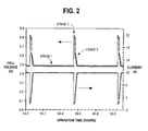
- the fuel cell 10 is operated at constant or varying power, as required, with interruptions of the power at predetermined time intervals. These interruptions may occur irregularly but periodic interruptions may be preferred. This procedure is effected in three stages or steps as illustrated in Figure 2 . During stage one, switch 28 is closed and cell 10 provides power to load 24, while also charging capacitor 26. The duration of this stage is preferably greater than 30 minutes.
- stage two switch 28 is open so that external circuit 22 is open, that is, the cell is not providing load 24 with electrical power.
- the duration of this stage is preferably less than 30 seconds.
- stage three switch 28 is closed so that electric current again flows in circuit 22.
- the current does not have to be instantaneously returned to the value immediately prior to opening of switch 28, but can be ramped up to this value, either in stepwise fashion or linearly, for example, by means of variable resistor 31 in series with switch 28 or other means.
- the duration of stage three is about 2 minutes. In this way, the cell is subjected to periodic load interruptions, that is, periodic open circuit periods during which the flow of current in the circuit is interrupted.
- the above procedure has the effect of counteracting performance degradation of the cell 10.
- the procedure may be carried out manually or automatically, for example, by means of suitable software with the use of a computer.
- the cell 10 is held at open circuit, or if the current flow in the circuit 22 is reduced below the normal operating minimum output, the normal reactions of methanol oxidation at the anode and oxygen reduction at the cathode no longer occur or the progress of these reactions is reduced.
- the enhancement of cell performance is presumed to occur as a result of improvement of cathode mass transport properties, that is, improvement of transport of oxidant to the cathode catalyst that may arise from removal of reaction product (water) from the cathode.
- this operating procedure works to improve long-term performance of the cell 10 by recovering the reversible performance degradation of the cell 10 when held at open or almost open circuit.
- Possible processes occurring which may lead to recovery include improved water removal at the cathode, improved carbon dioxide and intermediates removal at the anode, and improved removal of crossover methanol oxidation products at the cathode.
- the frequent repetition of the recovery technique counteracts the cell 10 from reaching highly degraded states which may become permanent over time and from operating at low cell potentials where other processes may occur to further degrade the cell 10.
- cell 10 While the operation of cell 10 has been described using capacitor 28 or other suitable storage device, it will be understood that cell 10 may be operated without the use of a capacitor in which case power supply to load 24 can be interrupted.
- fuel cell stacks 30, 32, 34 and 36 are shown connected to a load 40.
- a capacitor 42 is connected in parallel with load 40.
- Each of the fuel cell stacks 30, 32, 34, 36 comprises a plurality of individual fuel cells 44 connected together in series and housed between conductive current collector plates 46 (positive) and 48 (negative).
- the plates 46 are connected together by means of conductor 50, which is provided with switches 1a, 2a, 3a and 4a, as shown.
- plate 48 of stack 30 is connected to plate 46 of stack 32, through switch 1.
- plate 48 of stack 32 is connected to plate 46 of stack 34 through switch 2 and plate 48 of stack 34 is connected to plate 46 of stack 36 through switch 3.
- This configuration allows one or more of the stacks 30, 32, 34 and 36 to be held at open circuit individually while the other stacks still provide electricity to the load 40. For example, if stack 30 is to be held at open circuit then switches 1a, 2, and 3 will be closed while switches 1, 2a, 3a and 4a will be open. If stack 34 is to be held at open circuit then switches 1, 2 and 3a will be closed, while switches 1a, 2a, 3 and 4a will be open. In this manner the current by-passes the chosen stack and the stack remains at open circuit until the switches are changed to allow current to flow through the stack.
- each of the stacks can be operational and individual stacks can be held at open circuit when desired, while the remainder of the stacks still provide power.
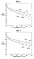
- Polarization plots (voltage versus current densities) are shown in Figure 3 and illustrate the cathode mass transport degradation of a DMFC (single cell A) operated continuously at 200 mA/cm 2 for 16 hours.
- Plots A1(O 2 ) and A1(air) show the initial polarization results for the DMFC when operated on pure oxygen or air oxidant respectively.
- the effect that diluting the oxidant stream with about 80% inert gas (nitrogen) has on initial performance is indicated by the difference between plots A1(O 2 ) and A1(air).
- Plots A2(O 2 ) and A2(air) show the polarization results for the same cell on pure oxygen and air respectively after only 16 hours of continuous operation.
- Figure 4 shows polarization results for a similar DMFC (cell B) that had been operated for 1978 hours with periodic load interruptions wherein the cell was open circuited every 30 minutes for a period of 30 seconds and then the load was ramped up to normal over a period of 2 minutes (a "30 minute/30 second recovery cycle").
- Plots B1(O 2 ) and B1(air) show the initial performance on pure oxygen and air respectively and plots B2(O 2 ) and B2(air) show the performance after 1978 hours of operation on pure oxygen and air respectively.
- the difference between the air and pure oxygen polarization plots has not changed substantially after prolonged operation (that is, the difference B2(air)-B2(O 2 ) is about the same as the difference B1(air)-B1(O 2 ) even after prolonged operation).
- the load interruption method allowed the cell to operate over 120 times longer with less performance degradation.
- Figures 5a-d show AC impedance spectra of the electrodes in certain tested DMFCs.
- a spectrum is taken of the complete DMFC operating under normal conditions (that is, oxidant and fuel are supplied to the cathode and anode respectively) which gives the spectrum of the combined impedances of cathode, electrolyte, and anode.
- a spectrum is obtained under similar conditions but with nitrogen gas supplied to the cathode, thus essentially making the cathode a reference electrode.
- the spectrum obtained in this case is then that of the combined impedances of electrolyte and anode.
- the spectrum of the cathode is then derived by taking the difference between the two spectra.
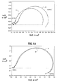
- Figures 5a and 5b are AC impedance spectra of DMFCs that are also illustrative of the effect that the inventive method has on cathode mass transport degradation. The spectra were taken at 250 mA/cm 2 over a frequency range from 65 KHz to 0.21 Hz.
- Figure 5a shows the AC impedance spectra for the cathode electrode of a DMFC (cell C) similar to those of Figures 3 and 4 .
- the DMFC of Figure 5a however had been operated for 1090 hours and an attempt was made to improve performance via a different anode starvation recovery procedure every 24 hours (involving starving the anode of fuel which causes a temporary change in anode potential).
- Plot C1 shows the initial cathode impedance spectrum and plot C2 shows the spectrum after 1090 hours of operation. The cathode impedance has increased substantially.
- Figure 5b shows the cathode impedance spectra for the aforementioned DMFC (cell B) of Figure 4 .
- Plot B1 shows the initial cathode impedance spectrum and plot B2 shows the spectrum after 1978 hours of operation. There is no significant increase in cathode impedance.
- Figure 5c and 5d are also presented to show the AC impedance of the anodes plus electrolytes for the same two DMFCs. In this case, the spectra were taken at 50 mA/cm 2 .
- Figure 5c shows the AC impedance of the anode plus electrolyte of cell C initially (plot C1) and after 1090 hours of operation (plot C2).
- Figure 5d shows the AC impedance spectrum of the anode plus electrolyte of cell B initially (plot B1) and after 1978 hours of operation (plot B2).
- Table 1 shows the degradation rate of cell voltage for the DMFC of Figure 4 when subjected to various combinations of load application time, open circuit time, and ramp time (that is, stage 1, stage 2, and stage 3 times). Each combination gave a lower degradation rate than that for continuous operation under load (1500 ⁇ V/hr as determined from operating continuously for 16 hours).
- Figure 6 shows a direct comparison of cell voltage versus operation time for a DMFC operated using the "30 minute/30 second recovery cycle” technique and a similar DMFC operated continuously under load.
- Plot C shows the voltage of the conventional DMFC which degraded at a rate of about 300 ⁇ V/hr.
- Plot I shows the voltage of the DMFC operated using the "30 minute/30 second recovery cycle” technique. After 1000 hours of testing, this DMFC showed a degradation rate of only about 26 ⁇ V/hr.
- the supply of fuel or oxidant or both fuel and oxidant to the anode and cathode, respectively may be interrupted. This system interruption should be timed to occur simultaneously with the current interruption stage two, described above.
- a direct methanol compact power stack comprising 10 fuel cells was then tested using two different recovery procedures. Over about the first 1200 hours of operation, the stack was switched to an open circuit condition every 24 hours for about 30 minutes. (On occasion, the stack stayed under load for more than 24 hours between open circuits). In addition, the flow of fuel and oxidant were also interrupted during these open circuit periods. Thereafter, periodic switching to an open circuit condition with reactant interruption continued using the "30 minute/30 second recovery cycle" procedure.
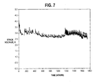
- Figure 7 shows the stack voltage of this stack versus operating time. Overall, a markedly improved 15 ⁇ V/hr per cell degradation rate was observed for over 1700 hours of operation at 200 mA/cm 2 .
Landscapes
- Life Sciences & Earth Sciences (AREA)
- Engineering & Computer Science (AREA)
- Sustainable Development (AREA)
- Sustainable Energy (AREA)
- Chemical & Material Sciences (AREA)
- Chemical Kinetics & Catalysis (AREA)
- Electrochemistry (AREA)
- General Chemical & Material Sciences (AREA)
- Manufacturing & Machinery (AREA)
- Fuel Cell (AREA)
- Inert Electrodes (AREA)
- Catalysts (AREA)
Description
- The present invention relates to a method of improving the performance of a direct feed fuel cell, such as a direct methanol fuel cell and/or fuel cell stack, as well as an apparatus for carrying out the method.
- Electrochemical fuel cells convert reactants, namely fuel and oxidant fluid streams, to generate electric power and reaction products. Electrochemical fuel cells generally employ an electrolyte disposed between two electrodes, namely a cathode and an anode. An electrocatalyst typically induces the desired electrochemical reactions at the electrodes. In addition to electrocatalyst, the electrodes may also comprise a porous electrically conductive sheet material, or electrode substrate, upon which the electrocatalyst is deposited. The electrocatalyst may be a metal black, an alloy or a supported metal catalyst such as, for example, platinum on carbon.
- A particularly interesting fuel cell is the solid polymer electrolyte fuel cell, which employs a membrane electrode assembly ("MEA"). The MEA comprises a solid polymer electrolyte or ion-exchange membrane disposed between the two electrode layers. Flow field plates for directing the reactants across one surface of each electrode substrate are typically disposed on each side of the MEA.
- A measure of electrochemical fuel cell performance is the voltage output from the cell for a given current density. Higher performance is associated with a higher voltage output for a given current density or higher current density for a given voltage output.
- A direct methanol fuel cell (DMFC) is a type of fuel cell in which methanol is directly oxidized at the anode. Although it may be operated on aqueous methanol vapour, a DMFC generally operates in a liquid feed mode on an aqueous methanol fuel solution. One problem which has been encountered with direct methanol fuel cells is performance degradation, that is, decrease in cell output voltage over time at a given current.
- Hamnett et al. (Hamnett, A., Weeks, S.A., Kennedy, B.J, Troughton, G., Christensen, P.A., "Long-Term Poisoning of Methanol Anodes", Ber. Bunsenges. Phys. Chem. 94, 1014-1020 (1990)) conducted a study of long-term poisoning of methanol anodes. The work was carried out on half cells and not complete fuel cells. Platinum anodes and platinum-ruthenium anodes with a 2.5 M H2SO4 electrolyte and a reference electrode (mercury/mercurous sulphate) were employed.
- With respect to pure platinum particle anodes, Hamnett et al. propose that poisoning on the electrode occurs by formation of a place-exchanged oxide which inhibits methanol adsorption. This oxide formation occurs at high anode potentials and can be removed at lower potentials, that is, open circuit. On the other hand, Hamnett et al. show that the amount of oxidised platinum when using a platinum-ruthenium anode is substantially greater that in the pure platinum anode. They further find that the amount of oxidised platinum decreases after extended polarisation and that it appears that the deactivation of platinum-ruthenium anodes is related to a gradual decrease in the amount of oxides on the platinum surface. They conclude that platinum-ruthenium anodes are poisoned by a different mechanism and expect that periodic open-circuiting of the platinum-ruthenium anode would not be so effective in enhancing the lifetime as for platinum anodes and they show test results demonstrating this.
- In another study Zelenay et al. (Zelenay, Piotr; Thomas, S.C., Gottesfeld, Shimshon, "Direct Methanol Fuel Cells: Recent Progress In Fuel Efficiency, Cell Performance And Performance Stability", Electrochemical Society Proceedings, Volume 98-27, 300-315) referring to active DMFC platinum-ruthenium anodes that can be operated for prolonged periods of time without noticeable loss in performance, teach that neither opening of the cell circuit nor stopping the feed of methanol is a prerequisite for stability of anode performance using platinum-ruthenium catalysts.
- Further,
WO 01/01508 A1 claims - The invention provides a method according to
claim 1, a fuel cell according toclaim 21 and a fuel cell assembly according to claim 27. - The method improves the performance of a direct feed fuel cell having an anode comprising a CO-tolerant catalyst, a solid polymer electrolyte and a cathode. The fuel cell normally produces power in a range from a minimum to a maximum output. The method comprises the steps of providing a supply of fuel to the anode for the oxidation of the fuel to produce an oxidation product and electrons at the anode; providing a supply of oxidant to the cathode for reduction of the oxidant, thereby producing a reduction product; and reducing the output power of the fuel cell to be less than the normal minimum output at predetermined time intervals, preferably periodically.
- Herein, a CO-tolerant catalyst is understood to be one having sites that adsorb carbon monoxide, but which can also adsorb an oxygen-containing species (for example, an OH group) near an adsorbed CO molecule at substantially lower potentials than a pure platinum catalyst. Examples are mixtures of platinum and certain elements, such as platinum-ruthenium, platinum-molybdenum, platinum-tin, platinum-tungsten, platinum-rhenium, platinumosmium, platinum-iridium, as well as certain ternary mixtures.
- The output power of the fuel cell is reduced by reducing the current from the fuel cell at predetermined time intervals. The circuit is switchable between a closed circuit condition in which the flow of electric current is permitted and an open circuit condition in which the flow of electric current is interrupted, reducing the output power of the fuel cell being effected by switching the current to the open circuit condition at predetermined time intervals.
- The step of reducing the electric current in the circuit at predetermined time intervals may comprise the steps of operating the cell to provide electric current in the circuit for an operating period of about 0.5 to 4 hours; opening the circuit to terminate the flow of electric current for a rest period of about 1 second to 30 minutes; and ramping the current to increase from zero to a working value for a ramping period of up to 5 minutes.
- The method may further comprise the step of interrupting the supply of fuel to the anode or the supply of oxidant to the cathode or both during the reduction of the output power of the fuel cell.
- A direct feed solid polymer electrolyte fuel cell comprises an anode having a CO-tolerant catalyst and a cathode; a fuel supply line for directing fuel to the anode for the oxidation of the fuel to produce an oxidation product and electrons at the anode; an oxidant supply line for directing oxidant to the cathode for reduction of the oxidant to produce a reduction product; an external electric circuit connectable to the fuel cell for receiving power from the fuel cell; and a current controller for reducing the flow of electric current in the external circuit at predetermined time intervals.
- The current controller comprises a switch in the external circuit for switching the circuit to an open circuit condition at predetermined time intervals in which the flow of electric current in the circuit is interrupted.
- The current controller may comprise a variable resistor in the external circuit for varying the flow of electric current in the external circuit at predetermined time intervals.
- A fuel cell assembly comprises a plurality of fuel cell stacks connected together in series for providing electric power to a load. Each fuel cell comprises an anode having a CO-tolerant catalyst, a solid polymer electrolyte and a cathode, and a switching assembly for selectively disconnecting one or more of the fuel cell stacks from the load while the remainder of the fuel cell stacks remain connected to the load.
- Further objects and advantages of the present method will become apparent from the description of preferred embodiment(s) below.
-
-
Figure 1a is a diagrammatic illustration of a solid polymer electrolyte fuel cell connected to a load in an external circuit; -
Figure 1b is a diagrammatic illustration of a plurality of fuel cell stacks in series connected to a load in an external circuit; -
Figure 2 is a plot of fuel cell voltage versus operation time, which illustrates periodically reducing the output power of the fuel cell; -
Figure 3 shows polarization plots which illustrate the cathode mass transport degradation of a DMFC (single cell) operated continuously for a period of time; -
Figure 4 shows polarization plots for a cell similar toFigure 3 but with the cell being operated with periodic load interruptions; -
Figures 5a and 5b show AC impedance spectra of DMFCs that illustrate the effect of periodic load interruptions on cathode mass transport degradation; - Figures 5c and
5d show the AC impedance of the anodes for the same two DMFCs ofFigures 5a and 5b ; -
Figure 6 is a plot showing a direct comparison of cell voltage versus operation time for a DMFC operated using a 30 minute/30 second recovery cycle technique and a similar DMFC operated continuously under load; and -
Figure 7 is a plot of stack voltage versus operating time of a ten cell direct methanol fuel cell stack operated using two different recovery procedures. - In
Figure 1a ,reference numeral 10 generally indicates a direct methanol fuel cell comprising ananode 12 and acathode 14 separated by apolymer electrolyte membrane 16. - The
cell 10 hasinlets anode 12 andcathode 14, respectively, as well as fuel andoxidant outlets -
Anode 12 andcathode 14 are connected by anexternal circuit 22 to anelectrical load 24. A storage device or charge storage means, such ascapacitor 26 is connected in parallel with theload 24. In place ofcapacitor 26 other suitable devices that act as buffers such, as a storage battery or the like, may be employed. Theexternal circuit 22 is further provided with aswitch 28 for opening andclosing circuit 22 to the flow of electric power to load 24. Whenswitch 28 is closed,cell 10 also charges thecapacitor 26. Whenswitch 28 is open,fuel cell 10 is disconnected from theload 24. During thistime capacitor 26 provides power to load 24 for a limited period of time. - A
resistor 29 is connected in parallel tofuel cell 10. Theresistor 29, which may be variable, is optionally provided and draws a limited amount of power fromfuel cell 10. For instance,resistor 29 may simply represent the power draw by a peripheral subsystem associated withfuel cell 10 such as a fan or pump. - During normal operation, load 24 itself may be varied and the power output from
fuel cell 10 would be varied accordingly between a normal operating minimum and maximum output (for example, in an automobile, the power output would vary between that required at idle and that required under full acceleration). Typically, the ratio of the maximum power output to that of the minimum power output (or "turndown ratio") for such a fuel cell system is less than about 60. InFigure 1a , the power consumed byresistor 29 is less than the normal operating minimum power output fromfuel cell 10. - A
variable resistor 31 is also provided incircuit 22.Variable resistor 31 may be operated whenswitch 28 is in the closed position in order to ramp the current up to a working value following an interruption period.Variable resistor 31 can also be used to preventcell 10 from instantaneously shorting at themoment switch 28 is closed. Alternatively,variable resistor 31 may be employed instead ofswitch 28 to reduce the current flow and therefore the output power of thecell 10 to less than the normal minimum power output ofcell 10. Theswitch 28 andresistor 31 can of course be combined in one unit, for example, a variable resistor which can shut off current flow completely or simply reduce the current flow as described above. The value ofvariable resistor 31 is such that its power consumption is negligible when compared to that ofload 24. - In the present example the fuel is an aqueous mixture of methanol that is supplied to the
anode 12 in either liquid or vapour form and the oxidant is oxygen gas or compressed air. - The
anode 12 comprises a CO-tolerant catalyst, such as a platinum-ruthenium (Pt-Ru) alloy. In the present example the anode comprises a porous carbon layer coated with the catalyst. - During normal operation of the
cell 10, methanol is oxidized at the anode. The oxidation products are CO2, H+ and electrons, although there are some intermediates or by-products which may be present, such as carbon monoxide (CO), formaldehyde (HCHO), formic acid (HCOOH), methyl formate (HCOOCH3) and dimethoxymethane (H2C(OCH3)2), depending upon the operating conditions. - At the cathode, water is produced. In addition water accumulates at the cathode due to electro-osmotic drag and diffusion from the anode. Depending on the membrane, some methanol may cross over to the cathode where it is oxidized. This results in methanol and its oxidation products being present at the cathode.
- The
fuel cell 10 is operated at constant or varying power, as required, with interruptions of the power at predetermined time intervals. These interruptions may occur irregularly but periodic interruptions may be preferred. This procedure is effected in three stages or steps as illustrated inFigure 2 . During stage one,switch 28 is closed andcell 10 provides power to load 24, while also chargingcapacitor 26. The duration of this stage is preferably greater than 30 minutes. - During stage two,
switch 28 is open so thatexternal circuit 22 is open, that is, the cell is not providingload 24 with electrical power. The duration of this stage is preferably less than 30 seconds. - During stage three,
switch 28 is closed so that electric current again flows incircuit 22. However the current does not have to be instantaneously returned to the value immediately prior to opening ofswitch 28, but can be ramped up to this value, either in stepwise fashion or linearly, for example, by means ofvariable resistor 31 in series withswitch 28 or other means. The duration of stage three is about 2 minutes. In this way, the cell is subjected to periodic load interruptions, that is, periodic open circuit periods during which the flow of current in the circuit is interrupted. - It has been found that the above procedure has the effect of counteracting performance degradation of the
cell 10. The procedure may be carried out manually or automatically, for example, by means of suitable software with the use of a computer. When thecell 10 is held at open circuit, or if the current flow in thecircuit 22 is reduced below the normal operating minimum output, the normal reactions of methanol oxidation at the anode and oxygen reduction at the cathode no longer occur or the progress of these reactions is reduced. Without being bound by theory, the enhancement of cell performance is presumed to occur as a result of improvement of cathode mass transport properties, that is, improvement of transport of oxidant to the cathode catalyst that may arise from removal of reaction product (water) from the cathode. Therefore, this operating procedure works to improve long-term performance of thecell 10 by recovering the reversible performance degradation of thecell 10 when held at open or almost open circuit. Possible processes occurring which may lead to recovery include improved water removal at the cathode, improved carbon dioxide and intermediates removal at the anode, and improved removal of crossover methanol oxidation products at the cathode. In addition, the frequent repetition of the recovery technique counteracts thecell 10 from reaching highly degraded states which may become permanent over time and from operating at low cell potentials where other processes may occur to further degrade thecell 10. - While the operation of
cell 10 has been described usingcapacitor 28 or other suitable storage device, it will be understood thatcell 10 may be operated without the use of a capacitor in which case power supply to load 24 can be interrupted. - Referring to
Figure 1b , fuel cell stacks 30, 32, 34 and 36 are shown connected to aload 40. Acapacitor 42 is connected in parallel withload 40. Each of the fuel cell stacks 30, 32, 34, 36 comprises a plurality ofindividual fuel cells 44 connected together in series and housed between conductive current collector plates 46 (positive) and 48 (negative). - The
plates 46 are connected together by means ofconductor 50, which is provided withswitches addition plate 48 ofstack 30 is connected to plate 46 ofstack 32, throughswitch 1. Likewise plate 48 ofstack 32 is connected to plate 46 ofstack 34 throughswitch 2 andplate 48 ofstack 34 is connected to plate 46 ofstack 36 throughswitch 3. - This configuration allows one or more of the
stacks load 40. For example, ifstack 30 is to be held at open circuit then switches 1a, 2, and 3 will be closed whileswitches stack 34 is to be held at open circuit then switches 1, 2 and 3a will be closed, whileswitches - With this type of configuration, each of the stacks can be operational and individual stacks can be held at open circuit when desired, while the remainder of the stacks still provide power.
- Polarization plots (voltage versus current densities) are shown in
Figure 3 and illustrate the cathode mass transport degradation of a DMFC (single cell A) operated continuously at 200 mA/cm2 for 16 hours. Plots A1(O2) and A1(air) show the initial polarization results for the DMFC when operated on pure oxygen or air oxidant respectively. The effect that diluting the oxidant stream with about 80% inert gas (nitrogen) has on initial performance is indicated by the difference between plots A1(O2) and A1(air). Plots A2(O2) and A2(air) show the polarization results for the same cell on pure oxygen and air respectively after only 16 hours of continuous operation. The difference between the air and pure oxygen polarization plots after continuous operation has become more substantial, particularly at higher current densities (that is, the difference A2(air) - A2(O2) is greater than the difference A1(air) - A1(O2), particularly at higher current densities). In comparison,Figure 4 shows polarization results for a similar DMFC (cell B) that had been operated for 1978 hours with periodic load interruptions wherein the cell was open circuited every 30 minutes for a period of 30 seconds and then the load was ramped up to normal over a period of 2 minutes (a "30 minute/30 second recovery cycle"). Plots B1(O2) and B1(air) show the initial performance on pure oxygen and air respectively and plots B2(O2) and B2(air) show the performance after 1978 hours of operation on pure oxygen and air respectively. The difference between the air and pure oxygen polarization plots has not changed substantially after prolonged operation (that is, the difference B2(air)-B2(O2) is about the same as the difference B1(air)-B1(O2) even after prolonged operation). The load interruption method allowed the cell to operate over 120 times longer with less performance degradation. -
Figures 5a-d show AC impedance spectra of the electrodes in certain tested DMFCs. In obtaining these spectra, first a spectrum is taken of the complete DMFC operating under normal conditions (that is, oxidant and fuel are supplied to the cathode and anode respectively) which gives the spectrum of the combined impedances of cathode, electrolyte, and anode. Then, a spectrum is obtained under similar conditions but with nitrogen gas supplied to the cathode, thus essentially making the cathode a reference electrode. The spectrum obtained in this case is then that of the combined impedances of electrolyte and anode. The spectrum of the cathode is then derived by taking the difference between the two spectra. -
Figures 5a and 5b are AC impedance spectra of DMFCs that are also illustrative of the effect that the inventive method has on cathode mass transport degradation. The spectra were taken at 250 mA/cm2 over a frequency range from 65 KHz to 0.21 Hz.Figure 5a shows the AC impedance spectra for the cathode electrode of a DMFC (cell C) similar to those ofFigures 3 and 4 . The DMFC ofFigure 5a however had been operated for 1090 hours and an attempt was made to improve performance via a different anode starvation recovery procedure every 24 hours (involving starving the anode of fuel which causes a temporary change in anode potential). Plot C1 shows the initial cathode impedance spectrum and plot C2 shows the spectrum after 1090 hours of operation. The cathode impedance has increased substantially. On the other hand,Figure 5b shows the cathode impedance spectra for the aforementioned DMFC (cell B) ofFigure 4 . Plot B1 shows the initial cathode impedance spectrum and plot B2 shows the spectrum after 1978 hours of operation. There is no significant increase in cathode impedance. - Figure 5c and
5d are also presented to show the AC impedance of the anodes plus electrolytes for the same two DMFCs. In this case, the spectra were taken at 50 mA/cm2. Figure 5c shows the AC impedance of the anode plus electrolyte of cell C initially (plot C1) and after 1090 hours of operation (plot C2).Figure 5d shows the AC impedance spectrum of the anode plus electrolyte of cell B initially (plot B1) and after 1978 hours of operation (plot B2). There is no significant difference in the anode plus electrolyte impedances before and after prolonged operation in either cell. The predominant loss in performance thus appears to originate from effects at the cathode. - Table 1 shows the degradation rate of cell voltage for the DMFC of
Figure 4 when subjected to various combinations of load application time, open circuit time, and ramp time (that is,stage 1,stage 2, andstage 3 times). Each combination gave a lower degradation rate than that for continuous operation under load (1500 µV/hr as determined from operating continuously for 16 hours).Table 1 Load On Steady (min) Stage 1Open Circuit(s) Stage 2Load On Ramp(s) Stage 3Degradation Rate (µV/hr) 27.5 30 120 26 27.5 3 120 6 237.5 30 120 50 29 30 30 0-70 27.5 30* 120 200-400 27.5 1 120 120 29.3 30 10 2 29.3 1 10 220 29 3 30 80 1440 30 120 170** * Cell was not open circuit but was operated at a reduced current density of 50 mA/cm2. ** 420 µV/hr over the first 1440 minute load on period. -
Figure 6 shows a direct comparison of cell voltage versus operation time for a DMFC operated using the "30 minute/30 second recovery cycle" technique and a similar DMFC operated continuously under load. Plot C shows the voltage of the conventional DMFC which degraded at a rate of about 300 µV/hr. Plot I shows the voltage of the DMFC operated using the "30 minute/30 second recovery cycle" technique. After 1000 hours of testing, this DMFC showed a degradation rate of only about 26 µV/hr. - In addition to interrupting the current, the supply of fuel or oxidant or both fuel and oxidant to the anode and cathode, respectively may be interrupted. This system interruption should be timed to occur simultaneously with the current interruption stage two, described above.
- A direct methanol compact power stack comprising 10 fuel cells was then tested using two different recovery procedures. Over about the first 1200 hours of operation, the stack was switched to an open circuit condition every 24 hours for about 30 minutes. (On occasion, the stack stayed under load for more than 24 hours between open circuits). In addition, the flow of fuel and oxidant were also interrupted during these open circuit periods. Thereafter, periodic switching to an open circuit condition with reactant interruption continued using the "30 minute/30 second recovery cycle" procedure.
Figure 7 shows the stack voltage of this stack versus operating time. Overall, a markedly improved 15 µV/hr per cell degradation rate was observed for over 1700 hours of operation at 200 mA/cm2. - While particular elements, embodiments and applications of the present invention have been shown and described, it will be understood, of course, that the invention is not limited thereto since modifications may be made by those skilled in the art without departing from the scope of the claims.
Claims (28)
- A method of improving the performance of a direct feed fuel cell having an anode comprising a CO-tolerant catalyst, a solid polymer electrolyte and a cathode, the fuel cell normally outputting power in a range from a minimum to a maximum output, comprising the steps of:providing a supply of fuel to the anode for the oxidation of the fuel to produce an oxidation product and electrons at the anode;providing a supply of oxidant to the cathode for reduction of the oxidant, thereby producing a reduction product;reducing the output power of the fuel cell at predetermined time intervals to be less than the normal minimum output,wherein the output power is provided to an external circuit, the circuit being switchable between a closed circuit condition in which the flow of electric current is permitted and an open circuit condition in which the flow of electric current is interrupted andcharacterized in thatreducing the output power of the fuel cell is effected by switching the circuit to the open circuit condition at predetermined time intervals.
- The method of claim 1, wherein the output power of the fuel cell is periodically reduced at predetermined time intervals.
- The method of claim 2, wherein the predetermined time intervals are from 0.5 hours to 4 hours.
- The method of claim 3, wherein the predetermined time intervals are 30 minutes.
- The method of claim 1, wherein the maximum output and the minimum output is in a ratio of up to 60:1.
- The method of claim 1, wherein the CO-tolerant catalyst comprises platinum and at least one element capable of adsorbing an oxygen-containing species at substantially lower potentials than a pure platinum catalyst.
- The method of claim 6, wherein the at least one element is selected from the group consisting of ruthenium, molybdenum, tin, tungsten, rhenium, osmium and iridium.
- The method of claim 1, wherein reducing the output power of the fuel cell is effected by reducing the output current from the fuel cell at predetermined time intervals.
- The method of claim 1, further comprising the step of interrupting the supply of fuel to the anode at predetermined time intervals when the output power of the fuel cell is reduced.
- The method of claim 1, further comprising the step of interrupting the supply of oxidant to the cathode at predetermined time intervals when the output power of the fuel cell is reduced.
- The method of claim 1, wherein the cathode comprises platinum as catalyst.
- The method of claim 1, wherein the fuel comprises methanol.
- The method of claim 12, wherein the fuel comprises a liquid aqueous methanol solution.
- The method of claim 1, wherein the circuit is switched to the closed position for a period of greater than 30 minutes.
- The method of claim 1 wherein the circuit is switched to the open position for a period of less than 30 seconds.
- The method of claim 1, wherein the step of reducing the output power of the fuel cell at predetermined time intervals comprises the steps of:operating the cell to provide electric current in the circuit for an operating period of 0.5 to 4 hours;opening the circuit to terminate the flow of electric current for a rest period of 1 second to 30 minutes; andramping the current to increase from zero to a working value for a ramping period of up to 5 minutes.
- The method of claim 16, wherein the operating period has a duration of greater than 30 minutes.
- The method of claim 16, wherein the rest period has a duration of less than 30 seconds.
- The method of claim 16, wherein the ramping period has a duration of less than 2 minutes.
- The method of claim 16, wherein the ramping period has a duration of greater than 10 seconds.
- A direct feed solid polymer electrolyte fuel cell comprising:an anode having a CO-tolerant catalyst and a cathode;a fuel supply line for directing fuel to the anode for the oxidation of the fuel to produce an oxidation product and electrons at the anode;an oxidant supply line for directing oxidant to the cathode for reduction of the oxidant to produce a reduction product; andan external electric circuit connectable to receive power from the fuel cell;characterized bya current controller periodically reducing the flow of electric current in the external circuit,wherein the current controller comprises a switch in the external circuit for periodically switching the circuit to an open circuit condition in which the flow of electric current in the circuit is interrupted.
- The fuel cell of claim 21, wherein the current controller comprises a variable resistor in the external circuit for periodically varying the flow of electric current in the external circuit.
- The fuel cell of claim 21, further comprising an electric charge storage device connected in parallel with the fuel cell in the external circuit.
- The fuel cell of claim 21, wherein the CO-tolerant catalyst comprises platinum and at least one element capable of adsorbing an oxygen-containing species.
- The fuel cell of claim 24, wherein the at least one element is selected from the group consisting of ruthenium, molybdenum, tin, tungsten and rhenium.
- The fuel cell of claim 25, wherein the CO-tolerant catalyst comprises a platinum-ruthenium alloy.
- A fuel cell assembly comprising:a plurality of direct feed fuel cell stacks connected together in series for providing electric power to a load, each fuel cell in the stacks comprising an anode having a CO-tolerant catalyst, a solid polymer electrolyte and a cathode;characterized bya switching assembly selectively disconnecting one or more of the fuel cell stacks from the load according to the method of claim 1, while the remainder of the fuel cell stacks remain connected to the load.
- The fuel cell assembly of claim 27, further comprising a charge storage device connected in parallel with the series-connected fuel cell stacks.
Applications Claiming Priority (2)
| Application Number | Priority Date | Filing Date | Title |
|---|---|---|---|
| US09/871,039 US6884530B2 (en) | 2001-05-31 | 2001-05-31 | Method of improving the performance of a direct feed fuel cell |
| US871039 | 2001-05-31 |
Publications (3)
| Publication Number | Publication Date |
|---|---|
| EP1263070A2 EP1263070A2 (en) | 2002-12-04 |
| EP1263070A3 EP1263070A3 (en) | 2004-12-08 |
| EP1263070B1 true EP1263070B1 (en) | 2012-10-03 |
Family
ID=25356582
Family Applications (1)
| Application Number | Title | Priority Date | Filing Date |
|---|---|---|---|
| EP02012094A Expired - Lifetime EP1263070B1 (en) | 2001-05-31 | 2002-05-31 | Method of improving the performance of a direct fuel feed fuel cell |
Country Status (5)
| Country | Link |
|---|---|
| US (1) | US6884530B2 (en) |
| EP (1) | EP1263070B1 (en) |
| CA (1) | CA2387547C (en) |
| DK (1) | DK1263070T3 (en) |
| ES (1) | ES2397056T3 (en) |
Families Citing this family (20)
| Publication number | Priority date | Publication date | Assignee | Title |
|---|---|---|---|---|
| CN1705890A (en) * | 2002-05-17 | 2005-12-07 | 绿光电力技术公司 | Method and apparatus for indicating a fault condition in fuel cells and fuel cell components |
| JP4017458B2 (en) * | 2002-07-05 | 2007-12-05 | 大同メタル工業株式会社 | Air-breathing fuel cell |
| JP3715608B2 (en) * | 2002-09-30 | 2005-11-09 | 株式会社東芝 | Electronic device system and battery unit |
| CN100361340C (en) * | 2003-07-18 | 2008-01-09 | 上海神力科技有限公司 | A control connection method for an integrated fuel cell stack |
| WO2005078846A1 (en) * | 2004-02-03 | 2005-08-25 | The Regents Of The University Of California | Dual electroreformer and fuel cell |
| JP2005322570A (en) * | 2004-05-11 | 2005-11-17 | Nissan Motor Co Ltd | Fuel cell system |
| JP2006032209A (en) * | 2004-07-20 | 2006-02-02 | Yamaha Motor Co Ltd | Direct methanol fuel cell system and transportation equipment using the same |
| JP4918714B2 (en) | 2004-09-16 | 2012-04-18 | セイコーインスツル株式会社 | Fuel cell system |
| JP2008522350A (en) * | 2004-11-29 | 2008-06-26 | ハイドロジェニクス コーポレイション | System and method for detecting and displaying a fault condition of an electrochemical cell |
| US8202661B2 (en) | 2006-06-27 | 2012-06-19 | Fuelcell Energy, Inc. | Method and system for recovering high power output operation of high temperature fuel cells using a rapid load recovery procedure |
| JP2008066081A (en) * | 2006-09-06 | 2008-03-21 | Fujitsu Ltd | Fuel cell device, control device and program |
| EP1986264A1 (en) * | 2007-04-26 | 2008-10-29 | Technische Universität München | System for generating electrical energy comprising an electrochemical reformer and a fuel cell |
| CN100452515C (en) * | 2007-04-27 | 2009-01-14 | 清华大学 | Direct Methanol Fuel Cell Consisting of Electrode Flow Channel Separated Stacks and Connected Stacks |
| US20100124679A1 (en) * | 2008-11-20 | 2010-05-20 | Mti Microfuel Cells, Inc. | Method for increasing the durability of direct oxidation fuel cells |
| US9397362B2 (en) * | 2009-01-16 | 2016-07-19 | Ford Motor Company | Modular fuel cell power system |
| KR20140072832A (en) | 2011-03-29 | 2014-06-13 | 유나이티드 테크놀로지스 코포레이션 | Fuel cell power plant control |
| EP2929582B1 (en) * | 2012-12-09 | 2018-08-29 | United Technologies Corporation | Flow battery with voltage-limiting device |
| US11056698B2 (en) | 2018-08-02 | 2021-07-06 | Raytheon Technologies Corporation | Redox flow battery with electrolyte balancing and compatibility enabling features |
| CN109309398B (en) * | 2018-09-30 | 2023-09-19 | 联想(北京)有限公司 | A processing method and power supply device |
| US11271226B1 (en) | 2020-12-11 | 2022-03-08 | Raytheon Technologies Corporation | Redox flow battery with improved efficiency |
Family Cites Families (9)
| Publication number | Priority date | Publication date | Assignee | Title |
|---|---|---|---|---|
| US3300345A (en) | 1964-09-03 | 1967-01-24 | Jr Ernest H Lyons | Electrolytic cell for producing electricity and method of operating the cell |
| JPS5344386B2 (en) | 1974-06-10 | 1978-11-28 | ||
| NL7903426A (en) | 1979-05-02 | 1980-11-04 | Electrochem Energieconversie | METHOD FOR OPERATING A FUEL CELL |
| JPH0824050B2 (en) | 1986-07-18 | 1996-03-06 | 株式会社日立製作所 | Operation method of fuel cell power generation system |
| JPH117974A (en) | 1997-06-18 | 1999-01-12 | Mitsubishi Electric Corp | Medium and large capacity fuel cell power generator |
| US6096448A (en) * | 1997-12-23 | 2000-08-01 | Ballard Power Systems Inc. | Method and apparatus for operating an electrochemical fuel cell with periodic fuel starvation at the anode |
| US6472090B1 (en) * | 1999-06-25 | 2002-10-29 | Ballard Power Systems Inc. | Method and apparatus for operating an electrochemical fuel cell with periodic reactant starvation |
| JP4623622B2 (en) | 1999-06-25 | 2011-02-02 | 東洋鋼鈑株式会社 | Manufacturing method of clad material for semiconductor package and manufacturing method of semiconductor package |
| US6554877B2 (en) * | 2001-01-03 | 2003-04-29 | More Energy Ltd. | Liquid fuel compositions for electrochemical fuel cells |
-
2001
- 2001-05-31 US US09/871,039 patent/US6884530B2/en not_active Expired - Lifetime
-
2002
- 2002-05-27 CA CA2387547A patent/CA2387547C/en not_active Expired - Lifetime
- 2002-05-31 EP EP02012094A patent/EP1263070B1/en not_active Expired - Lifetime
- 2002-05-31 DK DK02012094.5T patent/DK1263070T3/en active
- 2002-05-31 ES ES02012094T patent/ES2397056T3/en not_active Expired - Lifetime
Also Published As
| Publication number | Publication date |
|---|---|
| EP1263070A2 (en) | 2002-12-04 |
| CA2387547A1 (en) | 2002-11-30 |
| US20020192513A1 (en) | 2002-12-19 |
| ES2397056T3 (en) | 2013-03-04 |
| US6884530B2 (en) | 2005-04-26 |
| CA2387547C (en) | 2010-04-27 |
| DK1263070T3 (en) | 2013-01-07 |
| EP1263070A3 (en) | 2004-12-08 |
Similar Documents
| Publication | Publication Date | Title |
|---|---|---|
| US6884530B2 (en) | Method of improving the performance of a direct feed fuel cell | |
| US6517962B1 (en) | Fuel cell anode structures for voltage reversal tolerance | |
| US7226689B2 (en) | Method of making a membrane electrode assembly for electrochemical fuel cells | |
| US7608358B2 (en) | Fuel cell anode structure for voltage reversal tolerance | |
| US20070037042A1 (en) | Anode catalyst compositions for a voltage reversal tolerant fuel cell | |
| KR20090108032A (en) | Power systems | |
| US20080187813A1 (en) | Fuel cell anode structure for voltage reversal tolerance | |
| US20070154743A1 (en) | Micro-energy re-activating method to recover PEM fuel cell performance | |
| EP1964196A2 (en) | Membrane electrode assemblies for polymer electrolyte hydrogen and direct methanol fuel cells and methods for their production | |
| US11515555B2 (en) | Reversible shunts for overcharge protection in polymer electrolyte membrane fuel cells | |
| JP5450067B2 (en) | High performance cathode with controlled operating temperature range | |
| US12506167B2 (en) | Reversible shunts for overcharge protection in polymer electrolyte membrane fuel cells | |
| CN112956059B (en) | Methods and systems for operating electrochemical fuel cell stacks with improved performance recovery | |
| JP3758819B2 (en) | Disassembly method of solid oxide fuel cell | |
| KR101049827B1 (en) | Fuel cell system and its driving method | |
| US20180083299A1 (en) | Fuel cell driving method, fuel cell system, and vehicle | |
| KR100759430B1 (en) | Cathode catalyst for fuel cell, fuel cell membrane-electrode assembly comprising same and fuel cell system comprising same | |
| KR100599811B1 (en) | Membrane / electrode assembly for fuel cell and fuel cell system comprising same | |
| CA3118294C (en) | Method and system for operating an electrochemical fuel cell stack with improved performance recovery | |
| Ferreira et al. | 0.05 mgPt/cm² GAS DIFFUSION ELECTRODES |
Legal Events
| Date | Code | Title | Description |
|---|---|---|---|
| PUAI | Public reference made under article 153(3) epc to a published international application that has entered the european phase |
Free format text: ORIGINAL CODE: 0009012 |
|
| AK | Designated contracting states |
Kind code of ref document: A2 Designated state(s): AT BE CH CY DE DK ES FI FR GB GR IE IT LI LU MC NL PT SE TR |
|
| AX | Request for extension of the european patent |
Free format text: AL;LT;LV;MK;RO;SI |
|
| PUAL | Search report despatched |
Free format text: ORIGINAL CODE: 0009013 |
|
| AK | Designated contracting states |
Kind code of ref document: A3 Designated state(s): AT BE CH CY DE DK ES FI FR GB GR IE IT LI LU MC NL PT SE TR |
|
| AX | Request for extension of the european patent |
Extension state: AL LT LV MK RO SI |
|
| 17P | Request for examination filed |
Effective date: 20050601 |
|
| RAP1 | Party data changed (applicant data changed or rights of an application transferred) |
Owner name: SFC SMART FUEL CELL AG |
|
| AKX | Designation fees paid |
Designated state(s): AT BE CH CY DE DK ES FI FR GB GR IE IT LI LU MC NL PT SE TR |
|
| 17Q | First examination report despatched |
Effective date: 20061123 |
|
| RAP1 | Party data changed (applicant data changed or rights of an application transferred) |
Owner name: SFC ENERGY AG |
|
| GRAP | Despatch of communication of intention to grant a patent |
Free format text: ORIGINAL CODE: EPIDOSNIGR1 |
|
| RIN1 | Information on inventor provided before grant (corrected) |
Inventor name: MUELLER, JENS Inventor name: MANMOHAN KAILA, MONICA Inventor name: ZHANG, JIUJUN Inventor name: BOEHM, GUSTAV Inventor name: COLBOW, KEVIN |
|
| RIN1 | Information on inventor provided before grant (corrected) |
Inventor name: COLBOW, KEVIN Inventor name: MANMOHAN KAILA, MONICA Inventor name: ZHANG, JIUJUN Inventor name: BOEHM, GUSTAV Inventor name: MUELLER, JENS |
|
| GRAS | Grant fee paid |
Free format text: ORIGINAL CODE: EPIDOSNIGR3 |
|
| GRAA | (expected) grant |
Free format text: ORIGINAL CODE: 0009210 |
|
| AK | Designated contracting states |
Kind code of ref document: B1 Designated state(s): AT BE CH CY DE DK ES FI FR GB GR IE IT LI LU MC NL PT SE TR |
|
| REG | Reference to a national code |
Ref country code: GB Ref legal event code: FG4D |
|
| REG | Reference to a national code |
Ref country code: CH Ref legal event code: EP Ref country code: AT Ref legal event code: REF Ref document number: 578348 Country of ref document: AT Kind code of ref document: T Effective date: 20121015 |
|
| REG | Reference to a national code |
Ref country code: IE Ref legal event code: FG4D |
|
| REG | Reference to a national code |
Ref country code: DE Ref legal event code: R096 Ref document number: 60243781 Country of ref document: DE Effective date: 20121129 |
|
| REG | Reference to a national code |
Ref country code: CH Ref legal event code: NV Representative=s name: BOVARD AG, CH |
|
| REG | Reference to a national code |
Ref country code: DK Ref legal event code: T3 |
|
| REG | Reference to a national code |
Ref country code: ES Ref legal event code: FG2A Ref document number: 2397056 Country of ref document: ES Kind code of ref document: T3 Effective date: 20130304 |
|
| REG | Reference to a national code |
Ref country code: NL Ref legal event code: VDEP Effective date: 20121003 |
|
| PG25 | Lapsed in a contracting state [announced via postgrant information from national office to epo] |
Ref country code: FI Free format text: LAPSE BECAUSE OF FAILURE TO SUBMIT A TRANSLATION OF THE DESCRIPTION OR TO PAY THE FEE WITHIN THE PRESCRIBED TIME-LIMIT Effective date: 20121003 Ref country code: SE Free format text: LAPSE BECAUSE OF FAILURE TO SUBMIT A TRANSLATION OF THE DESCRIPTION OR TO PAY THE FEE WITHIN THE PRESCRIBED TIME-LIMIT Effective date: 20121003 Ref country code: NL Free format text: LAPSE BECAUSE OF FAILURE TO SUBMIT A TRANSLATION OF THE DESCRIPTION OR TO PAY THE FEE WITHIN THE PRESCRIBED TIME-LIMIT Effective date: 20121003 |
|
| PG25 | Lapsed in a contracting state [announced via postgrant information from national office to epo] |
Ref country code: CY Free format text: LAPSE BECAUSE OF FAILURE TO SUBMIT A TRANSLATION OF THE DESCRIPTION OR TO PAY THE FEE WITHIN THE PRESCRIBED TIME-LIMIT Effective date: 20121003 Ref country code: GR Free format text: LAPSE BECAUSE OF FAILURE TO SUBMIT A TRANSLATION OF THE DESCRIPTION OR TO PAY THE FEE WITHIN THE PRESCRIBED TIME-LIMIT Effective date: 20130104 Ref country code: BE Free format text: LAPSE BECAUSE OF FAILURE TO SUBMIT A TRANSLATION OF THE DESCRIPTION OR TO PAY THE FEE WITHIN THE PRESCRIBED TIME-LIMIT Effective date: 20121003 Ref country code: PT Free format text: LAPSE BECAUSE OF FAILURE TO SUBMIT A TRANSLATION OF THE DESCRIPTION OR TO PAY THE FEE WITHIN THE PRESCRIBED TIME-LIMIT Effective date: 20130204 |
|
| PLBE | No opposition filed within time limit |
Free format text: ORIGINAL CODE: 0009261 |
|
| STAA | Information on the status of an ep patent application or granted ep patent |
Free format text: STATUS: NO OPPOSITION FILED WITHIN TIME LIMIT |
|
| 26N | No opposition filed |
Effective date: 20130704 |
|
| REG | Reference to a national code |
Ref country code: DE Ref legal event code: R097 Ref document number: 60243781 Country of ref document: DE Effective date: 20130704 |
|
| PG25 | Lapsed in a contracting state [announced via postgrant information from national office to epo] |
Ref country code: MC Free format text: LAPSE BECAUSE OF FAILURE TO SUBMIT A TRANSLATION OF THE DESCRIPTION OR TO PAY THE FEE WITHIN THE PRESCRIBED TIME-LIMIT Effective date: 20121003 |
|
| REG | Reference to a national code |
Ref country code: IE Ref legal event code: MM4A |
|
| PG25 | Lapsed in a contracting state [announced via postgrant information from national office to epo] |
Ref country code: IE Free format text: LAPSE BECAUSE OF NON-PAYMENT OF DUE FEES Effective date: 20130531 |
|
| PG25 | Lapsed in a contracting state [announced via postgrant information from national office to epo] |
Ref country code: TR Free format text: LAPSE BECAUSE OF FAILURE TO SUBMIT A TRANSLATION OF THE DESCRIPTION OR TO PAY THE FEE WITHIN THE PRESCRIBED TIME-LIMIT Effective date: 20121003 |
|
| PG25 | Lapsed in a contracting state [announced via postgrant information from national office to epo] |
Ref country code: LU Free format text: LAPSE BECAUSE OF NON-PAYMENT OF DUE FEES Effective date: 20130531 |
|
| REG | Reference to a national code |
Ref country code: FR Ref legal event code: PLFP Year of fee payment: 15 |
|
| REG | Reference to a national code |
Ref country code: FR Ref legal event code: PLFP Year of fee payment: 16 |
|
| REG | Reference to a national code |
Ref country code: FR Ref legal event code: PLFP Year of fee payment: 17 |
|
| PGFP | Annual fee paid to national office [announced via postgrant information from national office to epo] |
Ref country code: DE Payment date: 20210520 Year of fee payment: 20 Ref country code: FR Payment date: 20210522 Year of fee payment: 20 Ref country code: IT Payment date: 20210531 Year of fee payment: 20 |
|
| PGFP | Annual fee paid to national office [announced via postgrant information from national office to epo] |
Ref country code: DK Payment date: 20210522 Year of fee payment: 20 Ref country code: CH Payment date: 20210522 Year of fee payment: 20 Ref country code: ES Payment date: 20210601 Year of fee payment: 20 Ref country code: GB Payment date: 20210522 Year of fee payment: 20 Ref country code: AT Payment date: 20210525 Year of fee payment: 20 |
|
| REG | Reference to a national code |
Ref country code: DE Ref legal event code: R071 Ref document number: 60243781 Country of ref document: DE |
|
| REG | Reference to a national code |
Ref country code: DK Ref legal event code: EUP Expiry date: 20220531 |
|
| REG | Reference to a national code |
Ref country code: CH Ref legal event code: PL |
|
| REG | Reference to a national code |
Ref country code: GB Ref legal event code: PE20 Expiry date: 20220530 |
|
| REG | Reference to a national code |
Ref country code: AT Ref legal event code: MK07 Ref document number: 578348 Country of ref document: AT Kind code of ref document: T Effective date: 20220531 |
|
| PG25 | Lapsed in a contracting state [announced via postgrant information from national office to epo] |
Ref country code: GB Free format text: LAPSE BECAUSE OF EXPIRATION OF PROTECTION Effective date: 20220530 |
|
| REG | Reference to a national code |
Ref country code: ES Ref legal event code: FD2A Effective date: 20220905 |
|
| PG25 | Lapsed in a contracting state [announced via postgrant information from national office to epo] |
Ref country code: ES Free format text: LAPSE BECAUSE OF EXPIRATION OF PROTECTION Effective date: 20220601 |