EP1262749A2 - Angle, azimuth and displacement insensitive spectrophotometer for color printer color control systems - Google Patents
Angle, azimuth and displacement insensitive spectrophotometer for color printer color control systems Download PDFInfo
- Publication number
- EP1262749A2 EP1262749A2 EP02005146A EP02005146A EP1262749A2 EP 1262749 A2 EP1262749 A2 EP 1262749A2 EP 02005146 A EP02005146 A EP 02005146A EP 02005146 A EP02005146 A EP 02005146A EP 1262749 A2 EP1262749 A2 EP 1262749A2
- Authority
- EP
- European Patent Office
- Prior art keywords
- color
- spectrophotometer
- illumination
- test
- printed
- Prior art date
- Legal status (The legal status is an assumption and is not a legal conclusion. Google has not performed a legal analysis and makes no representation as to the accuracy of the status listed.)
- Granted
Links
Images






Classifications
-
- G—PHYSICS
- G01—MEASURING; TESTING
- G01J—MEASUREMENT OF INTENSITY, VELOCITY, SPECTRAL CONTENT, POLARISATION, PHASE OR PULSE CHARACTERISTICS OF INFRARED, VISIBLE OR ULTRAVIOLET LIGHT; COLORIMETRY; RADIATION PYROMETRY
- G01J3/00—Spectrometry; Spectrophotometry; Monochromators; Measuring colours
- G01J3/02—Details
-
- G—PHYSICS
- G01—MEASURING; TESTING
- G01J—MEASUREMENT OF INTENSITY, VELOCITY, SPECTRAL CONTENT, POLARISATION, PHASE OR PULSE CHARACTERISTICS OF INFRARED, VISIBLE OR ULTRAVIOLET LIGHT; COLORIMETRY; RADIATION PYROMETRY
- G01J3/00—Spectrometry; Spectrophotometry; Monochromators; Measuring colours
- G01J3/02—Details
- G01J3/0205—Optical elements not provided otherwise, e.g. optical manifolds, diffusers, windows
- G01J3/0208—Optical elements not provided otherwise, e.g. optical manifolds, diffusers, windows using focussing or collimating elements, e.g. lenses or mirrors; performing aberration correction
-
- G—PHYSICS
- G01—MEASURING; TESTING
- G01J—MEASUREMENT OF INTENSITY, VELOCITY, SPECTRAL CONTENT, POLARISATION, PHASE OR PULSE CHARACTERISTICS OF INFRARED, VISIBLE OR ULTRAVIOLET LIGHT; COLORIMETRY; RADIATION PYROMETRY
- G01J3/00—Spectrometry; Spectrophotometry; Monochromators; Measuring colours
- G01J3/46—Measurement of colour; Colour measuring devices, e.g. colorimeters
- G01J3/50—Measurement of colour; Colour measuring devices, e.g. colorimeters using electric radiation detectors
-
- G—PHYSICS
- G01—MEASURING; TESTING
- G01J—MEASUREMENT OF INTENSITY, VELOCITY, SPECTRAL CONTENT, POLARISATION, PHASE OR PULSE CHARACTERISTICS OF INFRARED, VISIBLE OR ULTRAVIOLET LIGHT; COLORIMETRY; RADIATION PYROMETRY
- G01J3/00—Spectrometry; Spectrophotometry; Monochromators; Measuring colours
- G01J3/46—Measurement of colour; Colour measuring devices, e.g. colorimeters
- G01J3/50—Measurement of colour; Colour measuring devices, e.g. colorimeters using electric radiation detectors
- G01J3/501—Colorimeters using spectrally-selective light sources, e.g. LEDs
-
- G—PHYSICS
- G01—MEASURING; TESTING
- G01J—MEASUREMENT OF INTENSITY, VELOCITY, SPECTRAL CONTENT, POLARISATION, PHASE OR PULSE CHARACTERISTICS OF INFRARED, VISIBLE OR ULTRAVIOLET LIGHT; COLORIMETRY; RADIATION PYROMETRY
- G01J3/00—Spectrometry; Spectrophotometry; Monochromators; Measuring colours
- G01J3/46—Measurement of colour; Colour measuring devices, e.g. colorimeters
- G01J3/50—Measurement of colour; Colour measuring devices, e.g. colorimeters using electric radiation detectors
- G01J3/504—Goniometric colour measurements, for example measurements of metallic or flake based paints
-
- G—PHYSICS
- G01—MEASURING; TESTING
- G01J—MEASUREMENT OF INTENSITY, VELOCITY, SPECTRAL CONTENT, POLARISATION, PHASE OR PULSE CHARACTERISTICS OF INFRARED, VISIBLE OR ULTRAVIOLET LIGHT; COLORIMETRY; RADIATION PYROMETRY
- G01J3/00—Spectrometry; Spectrophotometry; Monochromators; Measuring colours
- G01J3/46—Measurement of colour; Colour measuring devices, e.g. colorimeters
- G01J3/52—Measurement of colour; Colour measuring devices, e.g. colorimeters using colour charts
-
- G—PHYSICS
- G01—MEASURING; TESTING
- G01J—MEASUREMENT OF INTENSITY, VELOCITY, SPECTRAL CONTENT, POLARISATION, PHASE OR PULSE CHARACTERISTICS OF INFRARED, VISIBLE OR ULTRAVIOLET LIGHT; COLORIMETRY; RADIATION PYROMETRY
- G01J3/00—Spectrometry; Spectrophotometry; Monochromators; Measuring colours
- G01J3/46—Measurement of colour; Colour measuring devices, e.g. colorimeters
- G01J3/52—Measurement of colour; Colour measuring devices, e.g. colorimeters using colour charts
- G01J3/524—Calibration of colorimeters
-
- G—PHYSICS
- G01—MEASURING; TESTING
- G01N—INVESTIGATING OR ANALYSING MATERIALS BY DETERMINING THEIR CHEMICAL OR PHYSICAL PROPERTIES
- G01N21/00—Investigating or analysing materials by the use of optical means, i.e. using sub-millimetre waves, infrared, visible or ultraviolet light
- G01N21/84—Systems specially adapted for particular applications
- G01N21/8483—Investigating reagent band
-
- G—PHYSICS
- G01—MEASURING; TESTING
- G01J—MEASUREMENT OF INTENSITY, VELOCITY, SPECTRAL CONTENT, POLARISATION, PHASE OR PULSE CHARACTERISTICS OF INFRARED, VISIBLE OR ULTRAVIOLET LIGHT; COLORIMETRY; RADIATION PYROMETRY
- G01J3/00—Spectrometry; Spectrophotometry; Monochromators; Measuring colours
- G01J3/46—Measurement of colour; Colour measuring devices, e.g. colorimeters
- G01J3/50—Measurement of colour; Colour measuring devices, e.g. colorimeters using electric radiation detectors
- G01J3/51—Measurement of colour; Colour measuring devices, e.g. colorimeters using electric radiation detectors using colour filters
- G01J3/513—Measurement of colour; Colour measuring devices, e.g. colorimeters using electric radiation detectors using colour filters having fixed filter-detector pairs
Definitions
- the present invention relates to a color correction system, a low cost broad spectrophotometer and a system for more accurately measuring the color of a material.
- said limited plurality of illumination sources comprises less than approximately five LEDs providing a corresponding limited number of different spectral illuminations
- said at least one photodetector comprises a photodetector with plural photo-sites and plural different spectral responses.
- said plural photodetectors are mounted in a substantially circular pattern surrounding said common lens system to define a central axis.
- said plural photodetectors each have a projection lens system having approximately 1:1 imaging optics.
- Disclosed in the embodiments herein is an improved, low cost, color spectrophotometer for color calibration or correction systems, highly suitable to be used for, or incorporated into, the color calibration or control of various color printing systems or other on-line color control or color processing systems.
- the substantial angle is approximately 45°.
- the illumination system illumination of said illuminated sample area of said material provides a plurality of rapid sequential illuminations of different spectral illuminations.
- the plurality of separate photodetectors spaced arrayed around the illuminated sample area of said material are relatively evenly circularly positioned around said illuminated sample area.
- the illumination system illumination of said illuminated sample area of said material provides a plurality of rapid sequential illuminations of different spectral illuminations, wherein the plurality of separate photodetectors spaced arrayed around the illuminated sample area of said material are relatively evenly circularly positioned around said illuminated sample area.
- the disclosed spectrophotometer provides improved accuracy for color test surfaces which may be tilted, curved, non-planer or otherwise varying in angular orientation relative to the spectrophotometer. That is particularly desirable for enhancement of the accuracy of a non-contact spectrophotometer which can measure the colors or color densities of test surfaces spaced from the spectrophotometer, especially moving surfaces, such as printed paper sheets in the output path of a color printer, or toner or liquid ink test patches on a moving photoreceptor or other surface, or other moving color objects, webs or materials, without requiring the test surface material to be constrained against a reference surface or against the spectrophotometer.
- This freedom of movement of the test material, both transversely to, and variably spaced from, the spectrophotometer, can be quite desirable in various color measurement applications, such as allowing printed sheets to move freely between relatively widely spaced apart paper path baffles or guides.
- that freedom of movement can also allow the color test surface material or media to have variances in angular alignment relative to the spectrophotometer, which may be manifested by lead and trail edge curl or buckle induced by the media handling apparatus, or otherwise.
- the disclosed embodiments can desirably reduce measurement and output signal errors from such variances in angular alignment.
- plural different color emission LEDs sequentially project their respective illuminations substantially in parallel, perpendicularly to the color test target surface, rather than at an angle thereto, so as to provide a substantially circular, rather than elliptical, commonly illuminated area of the test target. That is, with all the LEDs centrally located together, their illumination pattern on the test target may be formed from rays that hit the target at approximately 90 degrees, i.e., normal to the target. This will produce a circular or nearly circular irradiance pattern on a selected area of the target when the target surface is at 90 degrees thereto.
- One or more photo-sensors may be optically oriented at 45 degrees to the test target to receive the reflected light from the illuminated test target.
- this circular LED irradiance pattern becomes only slightly elliptical, with little area change, and thus causes little variance in the target irradiance and, therefore, in the signals from the photo-sensors, hence providing improved spectrophotometer angular insensitivity.
- An additional feature for improved spectrophotometer accuracy in the disclosed embodiments is to provide averaging of the outputs of plural photodetectors which are angularly viewing the target irradiance area from different positions around it, on opposing sides, so as to average any varying angular and/or azimuthal reflectivity of the target area, and thus further increase the insensitivity to changes in alignment with the target area.
- the exemplary spectrophotometer of the embodiments is shown and described herein as an integral part of an automatic on-line continuous color correction system of a color printer. That is because such a low cost spectrophotometer may be affordably provided and easily mounted in the output paths of color printers for automatic measurement of automatically printed color test sheets, without any manual effort or intervention being required, and without interfering with normal printing or the normal movement of printed sheets in the output path of the printer.
- a low cost, relatively simple, spectrophotometer, as disclosed herein, is thus particularly (but not exclusively) highly desirable for such a "colorimetry" function for such an on-line printer color correction system.
- at least one dedicated spectrophotometer is being provided in each printer, its cost and other factors becomes much more significant, as compared to the high cost (and other unsuitability's for on-line use) of typical laboratory spectrophotometers.
- a spectrophotometer may be mounted in the paper path of the moving copy sheets in the printer, preferably in the output path after fusing or drying, without having to otherwise modify the printer, or interfere with or interrupt normal printing, or the movement of the printed sheets in said paper path, and yet provide accurate color measurements of test color patches printed on the moving sheets as they pass the spectrophotometer. That enables a complete closed loop color control of a printer.
- color measurements, and/or the use of color measurements for various quality or consistency control functions are also important for many other different technologies and applications, such as in the production of textiles, wallpaper, plastics, paint, inks, etc.
- the disclosed color detection system may have applications in various such other fields where these materials or objects are to be color tested.
- the specific exemplary embodiment herein is part of a preferred automatic recalibration system with an on-line color printer color spectrophotometer, it will be appreciated that the disclosed spectrophotometer is not limited to that disclosed application.
- spectrophotometer may encompass a spectrophotometer, colorimeter, and densitometer, as broadly defined herein. That is, the word “spectrophotometer” may be given the broadest possible definition and coverage in the claims herein, consistent with the rest of the claim.
- various of the claims to a "spectrophotometer” in this application may encompass a similarly improved ETAC sensor densitometer used to measure the black or other color toner development on a moving photoreceptor surface or transfer belt.
- ETAC sensor densitometer used to measure the black or other color toner development on a moving photoreceptor surface or transfer belt.
- the definition or use of such above technical terms may also vary or differ among various scientists and engineers.
- a typical "spectrophotometer” measures the reflectance of an illuminated object of interest over many light wavelengths.
- Typical prior spectrophotometers in this context use 16 or 32 channels measuring from 400 nm to 700 nm or so, to cover the humanly visible color spectra or wavelength range.
- a typical spectrophotometer gives color information in terms of measured reflectances or transmittances of light, at the different wavelengths of light, from the test surface. (This is to measure more closely to what the human eye would see as a combined image of a broad white light spectra image reflectance, but the spectrophotometer desirably provides distinct electrical signals corresponding to the different levels of reflected light from the respective different illumination wavelength ranges or channels.)
- a “colorimeter” normally has three illumination channels, red, green and blue. That is, generally, a “colorimeter” provides its three (red, green and blue, or “RGB”) values as read by a light sensor or detector receiving reflected light from a color test surface sequentially illuminated with red, green and blue illuminators, such as three different color LEDs or three lamps with three different color filters. It may thus be considered different from, or a limited special case of, a "spectrophotometer", in that it provides output color information in the trichromatic quantity known as RGB.
- RGB red, green and blue
- Trichromatic quantities may be used for representing color in three coordinate space through some type of transformation.
- Other RGB conversions to "device independent color space” i.e., RGB converted to conventional L*a*b*
- RGB converted to conventional L*a*b* typically use a color conversion transformation equation, or a "lookup table" system, in a known manner.
- a "densitometer” typically has only a single channel, and simply measures the amplitude of light reflectivity from the test surface, such as a developed toner test patch on a photoreceptor, at a selected angle over a range of wavelengths, which may be wide or narrow.
- a single illumination source such as an IR LED, a visible LED, or an incandescent lamp may be used.
- the output of the densitometer detector is programmed to give the optical density of the sample.
- a densitometer of this type is basically "color blind". For example, a cyan test patch and magenta test patch could have the same optical densities as seen by the densitometer, but, of course, exhibit different colors.
- a multiple LED reflectance spectrophotometer may be considered to belong to a special case of spectrophotometers which normally illuminate the target with narrow band or monochromatic light. Others, with wide band illumination sources, can be flashed Xenon lamp spectrophotometers, or incandescent lamp spectrophotometers.
- a spectrophotometer is normally programmed to give more detailed, and broader spectra, reflectance values by using more than 3 channel measurements (e.g., 10 or more channel measurements), with conversion algorithms. That is in contrast to normal three channel colorimeters, which cannot give accurate, human eye related, reflectance spectra measurements, because they have insufficient measurements for that (only three measurements).
- the spectrophotometer of the disclosed embodiments is especially suitable for being mounted at one side of the printed sheets output path of a color printer to optically evaluate color imprinted output sheets as they move past the spectrophotometer, variably spaced therefrom, without having to contact the sheets or interfere with the normal movement of the sheets.
- it may be used to measure a limited number of color test patch samples printed by the printer on actual printed sheet output of the printer during regular or selected printer operation intervals (between normal printing runs or print jobs). These color test sheet printing intervals may be at regular timed intervals, and/or at each machine "cycle-up," or as otherwise directed by the system software.
- the spectrophotometer may be mounted at one side of the paper path of the machine, or, if it is desired to use duplex color test sheets, two spectrophotometers may be mounted on opposite sides of the paper path.
- Relatively frequent color recalibration of a color printer is highly desirable, since the colors actually printed on the output media (as compared to the colors intended to be printed) can significantly change, or drift out of calibration over time, for various known reasons. For example, changes in the selected or loaded print media, such as differences paper or plastic sheet types, materials, weights, calendaring, coating, humidity, etc. Or changes in the printer's ambient conditions, changes in the image developer materials, aging or wear of printer components, varying interactions of different colors being printed, etc. Printing test color patches on test sheets of the same print media under the same printing conditions during the same relative time periods as the color print job being color-controlled is thus very desirable.
- An additional feature which can be provided is to tailor or set the particular colors or combinations of the test patches on a particular banner or other test sheet to those colors which are about to be printed on the specific document for that banner sheet, i.e., the document pages which are to be printed immediately subsequent to that banner sheet (the print job identified by that banner sheet). This can provide a "real time" color correction for the color printer which is tailored to correct printing of the colors of the very next document to be printed.
- test patch images and colors may be automatically sent to the printer imager from a stored data file specifically designed for printing the dual mode banner sheet or other color test sheet page, and/or they may be embedded inside the customer job containing the banner page. That is, the latter may be directly electronically associated with the electronic document to be printed, and/or generated or transmitted by the document author or sender. Because the printed test sheet color patches colors and their printing sequence is known (and stored) information, the on-line spectrophotometer measurement data therefrom can be automatically coordinated and compared.
- the measured color signals may be automatically processed inside the system controller or the printer controller to produce or modify the tone reproduction curve, as explained in the cited references.
- the color test patches on the next test sheet may then be printed with that new tone reproduction curve. This process may be repeated so as to generate further corrected tone reproduction curves. If the printer's color image printing components and materials are relatively stable, with only relatively slow long term drift, and there is not a print media or other abrupt change, the tone reproduction curve produced using this closed loop control system will be the correct curve for achieving consistent colors for at least one or even a substantial number of customer print jobs printed thereafter, and only relatively infrequent and few color test sheets, such as the normal banner sheets, need be printed.
- RGB red, green, blue
- CMYK cyan, magenta, yellow, and black
- Real-world printers inherently have non-ideal printing materials, colors and behaviors, and therefore have complex non-linear colorimetric responses. Also, interactions between the cyan, magenta, and yellow imaging materials exist, especially on the printed output, which result in unwanted or unintended absorptions and/or reflections of colors. Even after a printer is initially calibrated, such that one or a range of input digital CMYK values produce proper colors, the full spectrum of CMYK values and printed colors will not be or remain fully accurate. In other words, the colors requested or directed to be printed by various input signals will not be the same as the actual colors printed.
- RGB coordinates are capable of addressing a look-up table having 256 3 locations, measuring and storing 256 3 values is time consuming and expensive.
- the look-up table is thus typically partitioned into a smaller size such as 16x16x16 (4096) table locations, each of which stores a four-dimensional CMYK value.
- Other CMYK values may then be found by interpolating the known CMYK values using an interpolation process, for example, trilinear or tetrahedral interpolation.
- the color correction look-up table may be built by sending a set of CMYK digital values to the printer, measuring the colorimetric RGB values of the resulting color patches outputted by the printer with a spectrophotometer, and generating the look-up table from the difference between the inputted values and the measured outputted values. More specifically, the color correction look-up table corrects for non-linearities, printing parameter variations, and unwanted absorptions of inks, so that the printer will print the true corresponding color.
- the actual printer response may tend to drift over time.
- the system is adjusted or recalibrated periodically. Recalibrating the color correction table involves periodically printing and remeasuring a set of test color patches which are then compared to an original set of color patches by calibration software. Remeasuring, however, has heretofore more typically been performed manually by a scanner or other measuring device which is remote from the printer being recalibrated.
- a test output sheet from the printer output tray, placing it (stationary) on a table and sliding a spectrophotometer over it, manually or with an X-Y plotter driver, or automatically feeding the test sheet through the spectrophotometer, and storing the spectrophotometer output signals data in an associated memory to read out later, or, connecting the spectrophotometer by an electrical wire or cable to the printer controller or its server to directly receive those color recalibration electrical input signals from the spectrophotometer and process them as described.
- the connecting cable could be replaced by known IR or RF wireless (such as "BlueTooth”) connection systems, as used in PC and other electronic components connections.
- spectrophotometer in high quality color reprographic applications, it is highly advantageous to monitor and update system colorimetric performance on-line and automatically through the use of an integrated spectrophotometer. That is, to have the printing device automatically fairly frequently generate calibration prints on otherwise normally printed sheets with color patches based on digital test pattern generations, and to have a spectrophotometer in the printer output which can read those moving sheet printed color test patches accurately to provide printed output color measurement signals, without manual intervention or printing interference.
- This requires a relatively low cost, yet fast, accurate, and wide spectral range spectrophotometer capable of effectively operating in that environment, and under those conditions, without interfering with normal printing operations. That is, being of sufficiently low cost such that this enhanced feature can be provided on commercial color printers without substantially increasing the total customer cost of those printers. That is not typical for conventional laboratory spectrophotometers.
- the disclosed spectrophotometer embodiment may be positioned at any convenient location along the normal paper path of a printing machine. It may even be fitted into the output sheet stacker tray of various existing color printer
- a specific feature of the specific embodiment disclosed herein is to provide a color correction system for a color printer having an output path for moving printed color sheets, including printed test sheets with printed color test patches, in which a spectrophotometer is mounted adjacent to said printer output path for sensing the colors printed on said printed color test patches on said printed test sheets as said printed test sheets are moving past said spectrophotometer in said output path, said color correction system including plural illumination sources for sequentially illuminating said color test patches with different illumination spectra in a substantially circular illumination pattern, and a plural photodetectors system for providing electrical output signals in response to the color of said test patches from said sequential illumination of said test patches by reflection of said illumination of said color test patches in said substantially circular illumination pattern by said illumination sources, and a plural lens system for transmitting said reflected illumination from said color test patches to said plural photodetectors system, so as to provide improved angular displacement insensitivity of said spectrophotometer relative to said printed test sheets.
- said plural photodetectors system comprises a plurality of photodetectors angularly spaced around said substantially circular illumination pattern to receive reflected illumination therefrom at substantially the same angle substantially from opposing directions; and/or wherein a common central lens system is provided, and wherein said different illumination spectra from said plural illumination sources for sequentially illuminating said color test patches in a substantially circular illumination pattern are perpendicularly aimed by said central lens system at substantially the same area of said color test patches on said printed test sheets to provide said substantially circular illumination pattern thereof; and/or wherein said plural illumination sources comprise a plurality of closely adjacent different spectral emission LEDs with a sequential actuation circuit; and/or a low cost broad spectrum spectrophotometer for measuring the colors of test target areas which may be variably displaced and variably angularly oriented relative to said spectrophotometer, comprising plural illumination sources and a common lens system for sequentially projecting plural different spectral illuminations from said plural illumination sources substantially
- the disclosed system may be connected, operated and controlled by appropriate operation of conventional control systems. It is well-known and preferable to program and execute various control functions and logic with software instructions for conventional or general purpose microprocessors, as taught by numerous prior patents and commercial products. Such programming or software may of course vary depending on the particular functions, software type, and microprocessor or other computer system utilized, but will be available to, or readily programmable without undue experimentation from functional descriptions, such as those provided herein, and/or prior knowledge of functions which are conventional, together with general knowledge in the software and computer arts. Alternatively, the disclosed control system or method may be implemented partially or fully in hardware, using standard logic circuits or single chip VLSI designs.
- sheet refers to a usually flimsy (non-rigid) physical sheet of paper, plastic, or other suitable physical substrate or print media for images, whether precut or web fed.
- a "copy sheet” may be abbreviated as a “copy,” or called a “hardcopy.”
- Printed sheets may be referred to as the "output.”
- a "print job” is normally a set of related printed sheets, usually one or more collated copy sets copied from a one or more original document sheets or electronic document page images, from a particular user, or otherwise related.
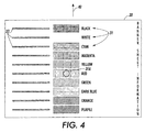
- this spectrophotometer 12 embodiment (or alternatives thereof) is particularly suited to be part of a highly effective yet economical on-line or "real time" color printing color calibration or correction system, which can regularly measure the actual colors currently being printed by a color printer such as 20 of Fig. 7 on banner or other printed test sheets such as 30 of Fig. 4 or 30' of Fig. 5, as compared to the intended or selected, or "true" colors of the electronic document images being inputted to the printer 20 for printing.
- the disclosed spectrophotometer 12 is not limited to that disclosed combination, application or utility.
- test patch illumination for color measurement should be at 45 degrees to the surface of the media on which the color test patch is printed.
- color test patch measurement should be performed using flux diffusely scattered from the (so-illuminated) test patch at 90 degrees (perpendicular) to that color test patch surface.
- a significant challenge in implementing a spectrophotometer to that standard is the repeatable collection of the reflected flux, as the amount of flux collected is proportional to the solid angle subtended by the entrance pupil of the flux collection optics.
- these standards can be met by the different architecture spectrophotometer 12 here, which instead illuminates the test surface at 90 degrees, and makes the color measurements of reflected light at 45 degrees to that illuminated test surface.
- prior spectrophotometers, colorimeters, and densitometers required that the measured target be held in a fixed predetermined position during measurement, typically accomplished by physically pressing the target material flat against a reference surface attached or held closely adjacent to the device's sense head.
- the position of print media in most existing printer paper paths, in the direction perpendicular to the paper path plane, is relatively uncontrolled in much of the paper path, since the paper normally is moved in between baffles which are much more widely spaced apart than the paper thickness, preferably by several millimeters, as illustrated here in Fig. 2.
- the paper may even be deliberately corrugated by corrugating feed rollers.
- the solution disclosed here is to instead provide a novel spectrophotometer 12 which is relatively insensitive to the relative displacement between the spectrophotometer and the color target media it is measuring. This is far more desirable, as it minimizes interference with the media, allows architectural versatility in the placement of the sensor, and, if done correctly, need add only a small increment in sensor UMC.
- a spectrophotometer 12 whose output is relatively insensitive to the displacement from the surface of the media under interrogation, yet which is compact and relatively inexpensive and thus suitable for cost-effective deployment in the regular (and unrestricted) output paper paths of conventional reprographic machines.
- spectrophotometer 12 of Fig. 2 flux from a selected sequential light source such as D1, D2, D3, or D4 (the particular light source being illuminated at that time) is shown being collimated by a common condensing lens 13 (with an IR filter 13A) and applied to a test patch 31 on the print media 30.
- An inverted image of the illuminated area is formed at the plane of the detectors D12 (D12A and D12B in Fig. 2) by projection (target) optics 18 and 19, which overfills the areas of the detectors D12.
- magnification varies as the inverse of the displacement, r ⁇ (-1), which produces a change in the image area proportional to r ⁇ (-2).
- image energy density i.e. energy per unit area
- the detector samples a fixed area within the image, its output is thereby also made invariant with spacing.
- this lens system for transmitting the illumination from the test patch to the photodetector sensor provides effective displacement insensitivity in the electrical signals provided by that photodetector sensor for variations in displacement between the test patch and the spectrophotometer of at least 6 millimeters. That allows a corresponding amount of lateral displacement freedom of movement tolerance (and opposing baffles spacing), and/or sheet curl or cockle tolerance, to be provided for all of the printed sheets, including the test sheets, in the output path of said color printer. That is, the test sheets do not have to be pressed against, or closely confined against, a reference surface or the spectrophotometer, and the printer output path does not have to be modified in that respect.
- An exemplary suitable focal length of the photosensor lens systems 18 and 19 can be about 11 mm. That appears to be a good tradeoff point between the amount of light energy desirably collected at the sensor and the achievement of displacement insensitivity in a reasonably sized spectrophotometer package. Different focal length lenses can be used, but the overall conjugate (the distance between the test patch and its image) would change correspondingly to maintain the same displacement insensitive behavior.
- each LED may be lit in sequence.
- the flux from each LED is collimated and centrally directed to be applied to the same test patch area under the center of the spectrophotometer in both 12 and 12'. That position is on the optical axis of the lens 13 or 13', which lens 13 or 13' is located in the center of the ring or circle of LEDs, as shown in Fig. 1.
- the reflectance of the test patch as a function of different wavelengths can be determined. With a sufficient number of plural different LED output wavelengths that reflectance of the same test patch as a function of different wavelengths can be extrapolated or interpolated over the entire visible spectra.
- An exemplary test patch size for the spectrophotometer 12 may be around 15 to 30 mm, and the measurement thereof may take only about 2 to 5 milliseconds or less.
- the photosensor is on the central or zero axis of the spectrophotometer to receive reflected light perpendicularly (at 90 degrees) from the illuminated area of the test target, and that illumination is by plural LEDs spaced around that central axis aimed at 45 degrees to the test target.
- the plural different color emission LEDs are together in one central unit, board, or chip, projecting light in parallel along the central or optical axis of the spectrophotometer at 90 degrees to the test target (e.g., the color patch on the moving sheet of paper), so as to provide a substantially circular, rather than elliptical, illuminated area of the test target.
- the test target e.g., the color patch on the moving sheet of paper
- One or more photo-sensors are optically oriented at 45 degrees to the test target to receive the reflected light from the test target. This change from a 45-0 degree system to a 0-45 degree system has been discovered to substantially reduce measurement errors from test target misalignment relative to the spectrophotometer.
- the angle of the test paper sheet surface relative to the central axis of the spectrophotometer can vary somewhat, for various reasons.
- their illumination pattern on the test target may be formed from rays that hit the target at approximately 90 degrees, i.e., normal to the target. This will produce a circular or nearly circular irradiance pattern on a selected area of the target when the target surface is at 90 degrees thereto, as intended.
- the flux reflected from the target and collected by the detectors is proportional to the irradiance. Since it may be seen that the irradiance (energy per unit area) varies very little for this 3 degrees example, only by 0.001, the signals from the detectors likewise vary very little.
- An additional disclosed feature in improving spectrophotometer accuracy for variable target angles is to provide, in addition to the above, the averaging of the outputs of plural photodetectors which are viewing the irradiance area from different positions around it, such as in Fig. 1, so as to average the varying azimuthal reflectivity of the target area, and thus further increase the insensitivity to angular misalignment with the target area.
- a detector on one side of the spectrophotometer central axis will view the illuminated target area at 45 minus 3 degrees, while a detector on the opposite side of the spectrophotometer will view the same illuminated area at 45 plus 3 degrees (or vice versa) but their output signals may be averaged to cancel out that effect, as by summing their outputs, as shown in Fig. 3.
- a spectrophotometer configuration of only three photosensor sites spaced around the central axis by 120 degrees from one another (and thus needing only 4 lenses in total) is sufficient to reduce measurement errors from that azimuthal source to less than one percent.
- the plural spaced detectors may be low cost single chip, multi-pixel, plural color, photo-detectors, with a reduced numbers of LEDs. However, that is not essential. Even with only three conventional individual single cell photosensors, the disclosed spectrophotometer configuration can reduce the number of LEDs from, e.g., 10, 12 or even 24 LEDs down to only eight LEDs. However, as will be described, by optionally using said plural color multiple photo-site detectors, as few as only three or four different LEDs may be employed and provide increased measurement speed and/or spectral coverage.
- the spectrophotometer 12' embodiment allows the spectrophotometer 12' embodiment to have a reduced total number of LEDs (e.g., only three or four) of appropriate different color spectral outputs to sequentially illuminate the exemplary color test targets 31 or 31' on exemplary test sheets 30 or 31' as in Figs. 4 or 5.
- the reflected illumination level is desirably not detected by a single photocell sensor or individual photocells. Instead, it may be detected by multiple spectral response photo-sites of a low cost color image sensor array chip 14, as in the example of Fig.
- those spectral measurements of an area of a test target may be converted to provide a true broad reflectance spectra, through known or other reconstruction and extrapolation algorithms.
- Both the number and spectra of the LED illuminators and the photosensor sites may be varied, where appropriate, and are not necessarily limited to the specific numbers and specific wavelengths of this specific embodiment example.
- each such chip 14 has three rows of such photo-sites (D12D, D12C and D12E here) manufactured with integral filters for red, green and blue, respectively.
- each chip 14 typically has integrated electronics; sample and hold circuitry, etc.
- the spectrophotometer 12 desirably utilizes at least one (or more, depending on the spectrophotometer design) of these low cost individual imaging chips 14. It is suggested here that chips 14 may be obtained from a manufacturer before they are fastened together into a document imaging bar.
- Such a known document imaging bar it may be made from twenty of such individual imaging chips 14, with each chip 14 being 16 mm long.
- Each such chip can read 400 x 660 pixels, provided by 248 photosensitive cells, with a 63.5 micro-meter pitch between cells.
- the cells are in three parallel rows, with filters for red, green and blue in the respective rows, as shown in the example of Fig. 5.
- These chips are made with integral electrical leads and connecting electronics already provided to all of these 248 photo-sites.
- another such row of photo-sites, D12F may be added to these chips, for white light (broad spectrum) sensing, by a relatively simple manufacturing modification. That is, by simply adding one more such parallel row of cells in the same silicon semiconductor manufacturing steps (or otherwise) to provide another row of otherwise identical or similar photo-sites, but having no color filtering layer formed over the cells.
- a different filter may be superimposed on the photo-sites of that added fourth row.
- the chip may be made with the same existing three rows of cells, but with every fourth cell in each row made without any filter. Or, every fourth cell in each row may be made a different filter. Some aperturing (exposed area reduction, such as by partial masking) may also be provided if desired for the unfiltered cells.
- a suitable such image sensor chip as is, or modified as described,may be considerably lower than a non-commercial photosensor. It can also provide a much higher level of circuit integration. Thus, a much more cost-effective spectrophotometer can be made therefrom than from individual photosensors, and a number of parallel sensing outputs can be provided.
- the exemplary color image sensor chip 14 may differ somewhat from a conventional document color image sensor array or bar in that some of the photo-sites (D12F) on the color image sensor array may be left un-covered, without any color filter layers.
- D12F photo-sites
- a fourth, broadband, spectral measurement is enabled from those unfiltered photo-sites along with the three different spectral measurements that the chip normally provides from its three differently colored filter covered photo-sites D12E, D12C and D12D.
- color image sensor array chips typically have three rows of photo-sites that are coated with 3 different color filter layers; red, green and blue, thus providing a three-color spectra measurement capability
- these same sensor array chips can be modified at low cost by simple modifications to provide an additional fourth spectral measurement capability. That is, modified so that some of the photo-sites are not color filtered.
- a broad spectrum illumination source such as a white light LED, may be used therewith in a spectrophotometer configuration, as further described herein.
- a spectrophotometer 12 with a suitable combination of a relatively small number of plural LEDs plus plural simultaneously exposed photo-sites, with an appropriate LED switching sequence to turn the LEDs on and off, can rapidly provide a large number of test target color measurements. As the number of measurements is so increased, the color measurement capability also becomes more accurate.
- LEDs can be used. However, it has been found that only a few LEDs having spectral output covering the sensitivity ranges of only two or more different types of photo-sites, plus a white LED or other light source, can provide a low total components count, and thus a lower cost, spectrophotometer, yet provide a relatively large number of spectra measurements.
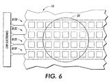
- Fig. 6 is a schematic and greatly enlarged portion of a exemplary color image sensor array chip 14 which may be utilized in the exemplary spectrophotometer.
- Show in Fig. 6 is an exemplary illuminated area 34 thereof. This area 34 is illuminated by LED illumination through lens 13, which is reflected from the test target area through the lens systems 18 and 19 to simultaneously illuminate multiple photo-sites in the three or four rows of each sensor chip 14.
- Those simultaneously illuminated photo-sites include the red, green, blue photo-sites D12D, D12C and D12E, and also the unfiltered photo-sites D12F if they are provided on the chip 14.
- Integration times used with various rows of the image sensor array chip 14 can be independently controlled to match the LED power levels to get suitable output signals from the sensor array.
- some of the photo-sites in one or more of these rows are desirably left uncovered (with no color filters) to get four spectral outputs from an otherwise conventional 3 row image sensor array.
- the photo-sites that are not covered with color filters will provide a much larger output signal than those that are covered with filters.
- part of the sensing area of these uncovered (unfiltered) photo-sites can be optionally coated in manufacturing with an opaque material or multiple layers of all three color filter layers to reduce their light sensitivity.
- any or all of the outputs of the sensor chip 14 may, of course, be calibrated/reconstructed to provide true reflectance values.
- spectrophotometer which combines the spectral differentiation capabilities of a low cost plural spectra image sensor 14 with the spectral outputs of a relatively small number of different LEDs to enable a cost effective, high performance, spectrophotometer.
- multiple measurements can be made and outputted in parallel corresponding to three or four different color image sensor outputs in parallel; cost can be reduced by reducing the number of LEDs and having lower detector and detector electronics costs; and the integration time of the three or four rows of a three or four row image sensor array can be adjusted independently to match the power levels of different LEDs.
- an alternative application, function, or option is to turn on, and leave on, only the white illumination source, for all of the color test patches being read at that time, to provide a "colorimeter" function of RGB values from the chip 14 outputs.
- the spectrophotometer 12 may be utilized with circuitry, such as that of Fig. 3, or otherwise, to accurately read reflected light from one or more different color test patches such as 31 printed on moving color test sheets 30 such as that shown in Fig. 4.
- the test sheets 30 may be conventionally printed on various print media such as conventional print papers or plastics, preferably the same print media as the planned or concurrent print job itself.
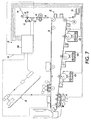
- the color test patches 31 may be printed in the same manner and by the same print apparatus as the regular print jobs by any of various different conventional color printer or printing systems, of which the xerographic printer 20 of Fig. 7 is merely one example.
- the disclosed spectrophotometer 12 can accurately read the colors of the test patches 31 even though the test sheets 30 are variably spaced from the spectrophotometer 12 during their color measurements, and are moving. Thus, the color measurements are not affected by normal variations in sheet surface positions in a normal paper path of a printer. This allows the simple mounting of the spectrophotometer 12 at one side of the normal printed sheets output path 40 of the printer 20 (or various other color reproduction systems).
- a photoreceptor belt 26 is driven by a motor M and laser latent imaged or exposed by a ROS polygon scanning system 24 after charging (or an LED bar).
- the respective images are developed by a black toner image developer station 41 and/or one or more of three different color toner image developer stations 42A, 42B, 42C.
- the toner images are transferred at a transfer station 32 to sheets of copy paper fed from an input tray stack 36.
- test sheets 30 are being printed instead of normal document images (at times, and with color tests, selected by the controller 100)
- each such test sheet 30 may be fed from the same or another sheet supply stack 36 and its test images transferred in the normal manner.
- the test sheet 30 is then outputted through the fuser 34 to the same normal output path 40, as if it were any other normal sheet being normally color printed.
- the test sheets 30 may be dual mode sheets also serving as banner sheets for print job separations, with typical printed banner sheet information, such as one or more of the user's name, the document title, the date and time, or the like.
- the spectrophotometer 12 here is mounted at one side of that output path 40 (or, it could even be mounted over the output tray 44) to sense the actual, fused, final colors being printed.
- the spectrophotometer output signals provide the input for the on-line color sensing and correction system 10, here with a microprocessor controller 100 and/or interactive circuitry and/or software.
- the controller 100, and sheet sensors along the machine 20 paper path conventionally controls the feeding and tracking of sheet positions within the printer paper path.
- the controller 100 and/or a conventional sensor for fiduciary marks 33 or the like on the test sheet 30 can provide control or actuation signals to the spectrophotometer 12 circuitry for the spectrophotometer 12 to sequentially test or read the colors of each of the test patches 31 on the test sheet 30 as that test sheet 30 moves past the spectrophotometer 12 in the output path 40.
- the test patches 31 can be variously located and configured, as blocks, strips, or otherwise, of various digitally selected solid color images.
- plural test sheets 30 of paper or other image substrate material being printed by the color printer 20 can be automatically printed with pre-programmed plural test patches 31 of defined colors, preferably with associated simple fiduciary marks for signaling the reading location of each colored test patch on the test sheet.
- Each test sheet 30 moves normally past the fixed position spectrophotometer 12, which is unobstructedly mounted at one side of the normal post-fuser machine output path 40 to both illuminate and view sheets passing thereby. This is in contrast to those prior systems requiring removing and holding a test sheet still, and moving a standard contact colorimeter or spectrophotometer over the test sheet.
- the normal target area in the system 10 embodiment herein is an area of a printed color test patch or patches 31 on the sheet of paper being otherwise normally printed and outputted.
- An alternate or calibration target area could be an unprinted area of the test paper sheet, or a white, grey, black or other color standardized test tile or surface automatically solenoid (or manually) inserted into the effective field of view of the spectrophotometer.
- the test target illumination by any one of the LEDs provides a variable level of light reflected from that target depending on the colors of the test patch and the selected illumination source.
- Fig. 2 illustrates, with dashed line light rays, both the LED target area illumination and the focusing of a portion of the reflected illumination therefrom by the projection lenses 18 and 19 (a simple two-element optic in this example).
- fiber optics or selfoc lenses could be utilized instead in other applications.
- fiber optics may be used to conduct the illumination from the LEDs.
- a collecting fiber optic may be used if desired, for example, to space the detecting photosensor remotely from the focal plane of the lenses.
- this low cost spectrophotometer 12 as mounted in the printer 20 copy sheet output path 40, can thus be part of a color correction system to automatically control and drive to color printing accuracy the printer 20 CMYK color generation with a small number of printed test sheets 30.
- the color correction system can sequentially look at a relatively small series of color test patterns printed on copy sheets as they are outputted.
- One or more mathematical techniques for color error correction with multiple spectrophotometer-detected output color signals for each color patch as input signals can provide for a greatly reduced number of required printed test patches, as shown in the above-cited references.
- the reflectance of the test patch as a function of different wavelengths can be determined, and that reflectance of the test patch, as a function of different wavelengths, can be extrapolated or interpolated over the entire visible spectra.
- An accurate color control system can thus regularly or almost constantly provide for testing and storing current machine color printing responses to color printing input signals (an up-to-date model) for remapping LAB (or XYZ) "device independent" color inputs (for later conversion to device dependent RGB or CMYK color space for printing). That information can also be profiled into a system or network server for each different machine (and/ or displayed on a CRT controller for color manipulation).
- the connecting circuitry may be set to ignore or threshold any only partially exposed cells (photo-sites) and/or may be set to only look at a fixed minimum number of centrally exposed cells, ignoring any signals from outer cells even if those outer cells are being illuminated by light reflected from the target.
- the connecting circuitry can also tell which cells are being exposed to which color from an illuminated test patch.
- plural color test patches can be simultaneously illuminated, yet can be desirably utilized for increased data. That is, more than one individual color test patch can be tested at a time by this spectrophotometer 12. However, that is not required here. Exposing (sensing) only one single color test patch at a time as shown in the above cross-referenced applications, several cited references, and in Fig. 4 here, may be utilized with conventional single-cell photosensors, such as D12A and D12B. The multiple signals provided from multiple photo-sites with plural different color filters may be utilized for analyzing the reflected light from either type of test target.
- Fig. 3 is a schematic or block diagram of an exemplary LED driver and signal processing circuits of the spectrophotometer 12 of Figs 1 and 2, portions of which are generally identified here for convenience as part of the controller 100, even though it could be, in whole or in part, a separate circuit, desirably having a single driver chip or die for all of the LEDs in the spectrophotometer itself.
- each LED is pulsed in turn by briefly turning on its respective transistor driver Q1 through Q4, by which the respective different spectra LEDs D1 through D4 are turned on by current from the indicated common voltage supply through respective resistors R1 through R4.
- each LED may be sequenced one at a time to sequentially transmit light though the condenser lens 13 shown in Fig. 2 and Fig. 14.
- LEDs in this example are turned on one at time in sequence, it will be appreciated that the system is not limited thereto. There may be measurement modes in which it is desirable to turn on more than one LED or other illumination source at once on the same target area.
- each actuated LEDs color or wavelength may measured by conventional circuitry or software for amplifying (112) and integrating (114) the respective outputs of the photodiode detector array of photo-sites, as generalized by D12 in Fig. 3, and directing this integrated signal information to a sample and hold stage 116. That stage 116 can provide an output signal indicated here as V out when released by an enabling signal input shown from circuit 110, which also provides an accompanying "Data Valid" signal.
- the corresponding LED pulsing and detector sampling rate is sufficiently non-critical and rapid for sampling each of multiple reasonable size color test patches on a normal size copy sheet moving by the spectrophotometer even for a high speed printer moving sheets rapidly through its paper path.
- the common LED driver voltage source to provide brief LED drive currents at a level above what is sustainable in a continuous current mode, higher flux detection signals can obtained and the test patch can thus be interrogated in a shorter time period.
- integrator 114 By integrating the signal, such as with integrator 114 here, enhanced signal to noise ratios can be achieved.
- Fig. 3 shows merely one example of a relatively simple and straightforward circuit. It, or various alternatives, can be readily implemented in an on-board hybrid chip or other architecture. Since the chip 14 of Fig. 6 has built-in electronics, the right-hand side circuitry of Fig. 3 may not be needed for its output.
- An additional conventional LED light emitter and detector may be integrated or separately mounted to detect black fiduciary or timing marks 33 printed on the test sheet 30 of Fig. 4, thereby providing an enable signal for illumination and reading within the respective color test patch areas.
- Those fiduciary marks 33 indicate the presence of an adjacent test patch 31 in the field of view of the spectrophotometer 12.
- fiducial marks 33 may not be needed.
- These fiducial marks 33 may be along side of their corresponding color test patch or patches area as shown in Fig. 4, or in between each (spaced apart) color test area. I.e., the fiducial marks may be parallel to, or in line with, the test patches in the direction of motion of the test sheet relative to the spectrophotometer.
- Individual calibration for each of the spectrophotometer's LED spectral energy outputs may be done by using a standard white (or other) tile test target of known reflectivity for the spectrophotometer to convert each LED measurement to absolute reflectance values.
- This calibration can be done frequently, automatically, and without removing the spectrophotometer from the printer with a standard white calibration tile test surface, such as 47 shown in Fig. 7, being manually, or preferably automatically (as by a solinoid), placed oppositely from the spectrophotometer 12, on the other side of the paper path 40 but in the field of view of the photosensor array and its lens system 13.
- a recalibration can be carried out without having to move or refocus the spectrophotometer.
- This or other calibration systems can convert the individual output energies of the respective LEDs at that point in time on the calibration tile 47 into respective individual reflectance measurement values from the photosensor array D12. That calibration data can then be electronically compared to previously stored standard characteristics data in the controller 100, or elsewhere, to provide calibration data for the spectrophotometer 12, which may be used for calibration of its other, color test patch generated, data.
- the calibration data can also be used to adjust the individual LED output energies to compensate for LED aging or other output changes, by adjusting the applied current or voltage (if that is individually programmable) or by increasing the respective turn-on times of the LEDs, where the photodetector D12 output signal is being integrated, as in this embodiment.
- Initial spectrophotometer calibration data may be stored in an integral PROM IC shipped with the spectrophotometer, if desired.
- LED output initial calibration data may be programmed into the software being used to analyze the output of the spectrophotometer in other known manners, such as loading it into the disc storage or other programmable memory of the printer controller 100 or system print server.
- spectrophotometers have been made using illumination sources other than LEDs.
- illumination sources other than LEDs.
- multiple electroluminescent (EL) emitters with filter and active layers as in HP U.S. 5,671,059 issued September 23, 1997, or incandescent lamps.
- white (instead of narrow spectrum) LED illuminators and plural sensors with different color filters are disclosed in EP 0 921 381 A2 published 09.06.1999 for a color sensor for inspecting color print on newspaper or other printed products.
Landscapes
- Physics & Mathematics (AREA)
- Spectroscopy & Molecular Physics (AREA)
- General Physics & Mathematics (AREA)
- Health & Medical Sciences (AREA)
- Life Sciences & Earth Sciences (AREA)
- Molecular Biology (AREA)
- Chemical & Material Sciences (AREA)
- Analytical Chemistry (AREA)
- Biochemistry (AREA)
- General Health & Medical Sciences (AREA)
- Immunology (AREA)
- Pathology (AREA)
- Spectrometry And Color Measurement (AREA)
- Investigating Or Analysing Materials By Optical Means (AREA)
Abstract
Description
Color correction and/or color control systems should not be confused with color registration systems or sensors. Those systems are for insuring that colors are correctly printed accurately superposed and/or accurately adjacent to one another, such as by providing positional information for shifting the position of respective color images being printed.
Ω = the solid angle subtended by the projection optics,
A = the area of the projection optics entrance pupil, and
r = the displacement between the test patch and the entrance optic.
As displacement changes, the amount of flux collected varies, and this variation will be indistinguishable at the electrical signal output from variations in the density of the patch, which will lead to errors in the measured density if not compensated for.
| LEDs | Number of Spectral Measurements | ||
| Types | Number | With 3 Color (R,G,B filters) Image Sensor | With 4 Color (R,G,B filters + no filter) |
| White | |||
| 1 | 3 | 4 | |
| White, + 595nm or 505nm | 2 | 5-6 | 7-8 |
| White, 595nm, 505nm | 3 | 7-9 | 10-12 |
| White, 595nm, 505nm, 430nm | 4 | 8-12 | 12-16 |
Claims (10)
- A color correction system for a color printer having an output path for moving printed color sheets, including printed test sheets with printed color test patches, in which a spectrophotometer is mounted adjacent to said printer output path for sensing the colors printed on said printed color test patches on said printed test sheets as said printed test sheets are moving past said spectrophotometer in said output path, said color correction system including plural illumination sources for sequentially illuminating said color test patches with different illumination spectra in a substantially circular illumination pattern, and a plural photodetectors system for providing electrical output signals in response to the color of said test patches from said sequential illumination of said test patches by reflection of said illumination of said color test patches in said substantially circular illumination pattern by said illumination sources, and a plural lens system for transmitting said reflected illumination from said color test patches to said plural photodetectors system, so as to provide improved angular displacement insensitivity of said spectrophotometer relative to said printed test sheets.
- The color correction system of claim 1, wherein said plural photodetectors system comprises a plurality of photodetectors angularly spaced around said substantially circular illumination pattern to receive reflected illumination therefrom at substantially the same angle from substantially opposing directions.
- The color correction system of claim 1 or 2, wherein a common central lens system is provided, and wherein said different illumination spectra from said plural illumination sources for sequentially illuminating said color test patches in a substantially circular illumination pattern are perpendicularly aimed by said central lens system at substantially the same area of said color test patches on said printed test sheets to provide said substantially circular illumination pattern thereof.
- The color correction system of claim 1, 2 or 3 wherein said plural illumination sources comprise a plurality of closely adjacent different spectral emission LEDs with a sequential actuation circuit.
- A low cost broad spectrum spectrophotometer for measuring the colors of test target areas which may be variably displaced and variably angularly oriented relative to said spectrophotometer, comprising plural illumination sources and a common lens system for sequentially projecting plural different spectral illuminations from said plural illumination sources substantially perpendicular to the color test target area to illuminate a substantially circular illumination area of the color test target area, a sequential actuation circuit for sequential actuation of said plural illumination sources, and at least one photodetector spaced from said common lens system and spaced from said substantially circular illumination area of the color test target area to angularly receive reflected light from said substantially circular illumination area, so as to provide reduced angular displacement sensitivity of said spectrophotometer relative to said color test target area.
- The low cost broad spectrum spectrophotometer of claim 5, wherein said at least one photodetector comprises a detector array of plural photodetectors spaced apart on at least two opposing sides of said common lens system and spaced from said substantially circular illumination area of the color test target area to differently angularly receive reflected light from said substantially circular illumination area at substantially the same angle from opposing directions, so as to provide additionally reduced angular displacement sensitivity of said spectrophotometer relative to said color test target area.
- The low cost broad spectrum spectrophotometer of claim 5, wherein said plural illumination sources comprise approximately eight or less LEDs providing a correspondingly limited number of different spectral illuminations.
- The low cost broad spectrum spectrophotometer of claim 5, wherein said spectrophotometer is a part of a color control system of a color printer with a printed sheets output path and is mounted adjacent to at least one side of the printed sheets output path of said color printer and said illuminated color test target area is printed on a printed color test sheet printed by said printer and moving past said spectrophotometer in said printed sheets output path of said color printer.
- A low cost broad spectrum spectrophotometer comprising means for sequentially perpendicularly illuminating a common substantially circularly illuminated color test area with a limited plural number of different spectra illuminations, and means for sequentially measuring the angularly reflected illumination from said sequentially illuminated substantially circularly illuminated color test area by applying said reflected illumination simultaneously to plural photodetectors spaced around said common color test area and summing the outputs of said photodetectors to provide an averaged output.
- A system for accurately measuring the color of a material comprising:an illumination system for illumination of a sample area of said material approximately perpendicularly thereto,and a color measurement system with a plurality of separate photodetectors for measuring the color reflected from said illumination system illumination of said sample area of said material at a substantial angle to said illuminated sample area of said material,said plurality of separate photodetectors being spaced arrayed around said illuminated sample area of said material to receive said reflected illumination from said illuminated sample area of said material from substantially opposing directions and from substantial angle to said illuminated sample area of said material.
Applications Claiming Priority (2)
| Application Number | Priority Date | Filing Date | Title |
|---|---|---|---|
| US09/862,945 US6633382B2 (en) | 2001-05-22 | 2001-05-22 | Angular, azimuthal and displacement insensitive spectrophotometer for color printer color control systems |
| US862945 | 2001-05-22 |
Publications (3)
| Publication Number | Publication Date |
|---|---|
| EP1262749A2 true EP1262749A2 (en) | 2002-12-04 |
| EP1262749A3 EP1262749A3 (en) | 2004-01-07 |
| EP1262749B1 EP1262749B1 (en) | 2006-12-13 |
Family
ID=25339810
Family Applications (1)
| Application Number | Title | Priority Date | Filing Date |
|---|---|---|---|
| EP02005146A Expired - Lifetime EP1262749B1 (en) | 2001-05-22 | 2002-03-07 | Angle, azimuth and displacement insensitive spectrophotometer for color printer color control systems |
Country Status (7)
| Country | Link |
|---|---|
| US (3) | US6633382B2 (en) |
| EP (1) | EP1262749B1 (en) |
| JP (1) | JP2002365139A (en) |
| BR (1) | BR0201888A (en) |
| CA (1) | CA2373648C (en) |
| DE (1) | DE60216664T2 (en) |
| MX (1) | MXPA02005094A (en) |
Cited By (10)
| Publication number | Priority date | Publication date | Assignee | Title |
|---|---|---|---|---|
| WO2006101811A1 (en) * | 2005-03-22 | 2006-09-28 | Eastman Kodak Company | Method for monitoring image calibration |
| WO2007149376A3 (en) * | 2006-06-19 | 2008-06-19 | X Rite Inc | Industrially robust non-contact color measurement device |
| EP2096501A1 (en) * | 2008-02-15 | 2009-09-02 | Miyakoshi Printing Machinery Co., Ltd. | Electronic photograph printer |
| EP2270451A1 (en) * | 2009-06-24 | 2011-01-05 | X-Rite Europe GmbH | Colour measuring device |
| EP2429171A1 (en) * | 2010-09-08 | 2012-03-14 | Canon Kabushiki Kaisha | Image processing apparatus and control method for image processing apparatus |
| EP2600605A1 (en) * | 2011-11-30 | 2013-06-05 | AIT Austrian Institute of Technology GmbH | Method and a receiving device for receiving multispectral images |
| DE102012208248B3 (en) * | 2012-05-16 | 2013-08-29 | Astech Angewandte Sensortechnik Gmbh | Method for distance variation compensated contactless point-reflection measurement of intensities of non-luminous objects, involves computing compensation signals for distance-related variation error of intensities of main reception channel |
| EP2812187A4 (en) * | 2012-02-07 | 2015-07-08 | Hewlett Packard Development Co | COLOR ANALYSIS |
| WO2017207013A1 (en) * | 2016-05-31 | 2017-12-07 | Hp Indigo B.V. | Printer with spectrophometric measurement |
| WO2019134844A1 (en) * | 2018-01-08 | 2019-07-11 | Robert Bosch Gmbh | Optical sensor module for spectroscopic measurement |
Families Citing this family (194)
| Publication number | Priority date | Publication date | Assignee | Title |
|---|---|---|---|---|
| US7034942B2 (en) * | 2002-01-07 | 2006-04-25 | Hewlett-Packard Development Company, L.P. | Color measurement device and color measurement method |
| EP1480026A1 (en) * | 2003-05-22 | 2004-11-24 | Ecole d'Ingenieurs du Canton de Neuchatel | Color identification device |
| US7226049B2 (en) | 2003-06-06 | 2007-06-05 | Xerox Corporation | Universal flexible plural printer to plural finisher sheet integration system |
| DE50307469D1 (en) * | 2003-07-23 | 2007-07-26 | Gretag Macbeth Ag | Spectrophotometer and associated measuring head |
| US7262853B2 (en) * | 2003-09-23 | 2007-08-28 | X-Rite, Inc. | Color measurement instrument |
| US7383261B2 (en) * | 2004-01-16 | 2008-06-03 | Xerox Corporation | Reference database and method for determining spectra using measurements from an LED color sensor, and method of generating a reference database |
| DE102004003613B4 (en) * | 2004-01-25 | 2015-01-08 | grapho metronic Meß- und Regeltechnik GmbH | Apparatus for capturing an image from a predetermined portion of a moving piece of printed matter |
| US7396012B2 (en) * | 2004-06-30 | 2008-07-08 | Xerox Corporation | Flexible paper path using multidirectional path modules |
| EP1621857A3 (en) * | 2004-07-29 | 2006-04-12 | MHT Optic Research AG | Device for the determination of the colour value of transparent objects, in particular teeth |
| US7423280B2 (en) | 2004-08-09 | 2008-09-09 | Quad/Tech, Inc. | Web inspection module including contact image sensors |
| US7188929B2 (en) * | 2004-08-13 | 2007-03-13 | Xerox Corporation | Parallel printing architecture with containerized image marking engines |
| US7206532B2 (en) * | 2004-08-13 | 2007-04-17 | Xerox Corporation | Multiple object sources controlled and/or selected based on a common sensor |
| US20070002085A1 (en) * | 2005-06-30 | 2007-01-04 | Xerox Corporation | High availability printing systems |
| US7787138B2 (en) * | 2005-05-25 | 2010-08-31 | Xerox Corporation | Scheduling system |
| US7308218B2 (en) * | 2005-06-14 | 2007-12-11 | Xerox Corporation | Warm-up of multiple integrated marking engines |
| US7542059B2 (en) * | 2006-03-17 | 2009-06-02 | Xerox Corporation | Page scheduling for printing architectures |
| US7493055B2 (en) * | 2006-03-17 | 2009-02-17 | Xerox Corporation | Fault isolation of visible defects with manual module shutdown options |
| US7302199B2 (en) * | 2005-05-25 | 2007-11-27 | Xerox Corporation | Document processing system and methods for reducing stress therein |
| US7649645B2 (en) | 2005-06-21 | 2010-01-19 | Xerox Corporation | Method of ordering job queue of marking systems |
| US7224913B2 (en) * | 2005-05-05 | 2007-05-29 | Xerox Corporation | Printing system and scheduling method |
| US7123873B2 (en) * | 2004-08-23 | 2006-10-17 | Xerox Corporation | Printing system with inverter disposed for media velocity buffering and registration |
| US7024152B2 (en) * | 2004-08-23 | 2006-04-04 | Xerox Corporation | Printing system with horizontal highway and single pass duplex |
| US7245838B2 (en) * | 2005-06-20 | 2007-07-17 | Xerox Corporation | Printing platform |
| US7742185B2 (en) | 2004-08-23 | 2010-06-22 | Xerox Corporation | Print sequence scheduling for reliability |
| US8407077B2 (en) * | 2006-02-28 | 2013-03-26 | Palo Alto Research Center Incorporated | System and method for manufacturing system design and shop scheduling using network flow modeling |
| US7136616B2 (en) * | 2004-08-23 | 2006-11-14 | Xerox Corporation | Parallel printing architecture using image marking engine modules |
| US7619769B2 (en) * | 2005-05-25 | 2009-11-17 | Xerox Corporation | Printing system |
| US9250967B2 (en) * | 2004-08-23 | 2016-02-02 | Palo Alto Research Center Incorporated | Model-based planning with multi-capacity resources |
| JP2006072058A (en) * | 2004-09-03 | 2006-03-16 | Pentax Corp | Laser scanning device |
| US7351245B2 (en) * | 2004-09-21 | 2008-04-01 | Bernice Joy Rozinsky | Apparatus and method for dislodging object from throat |
| US7336920B2 (en) * | 2004-09-28 | 2008-02-26 | Xerox Corporation | Printing system |
| US7324779B2 (en) * | 2004-09-28 | 2008-01-29 | Xerox Corporation | Printing system with primary and secondary fusing devices |
| US7751072B2 (en) * | 2004-09-29 | 2010-07-06 | Xerox Corporation | Automated modification of a marking engine in a printing system |
| JP2008518218A (en) * | 2004-10-28 | 2008-05-29 | グレターク−マクベス・アーゲー | Measuring device and scanning device for photoelectrically measuring a measurement object based on pixels |
| WO2006046249A1 (en) * | 2004-10-28 | 2006-05-04 | Vcortex Ltd. | Density measurement, colorimetric data, and inspection of printed sheet using contact image sensor |
| US7310108B2 (en) | 2004-11-30 | 2007-12-18 | Xerox Corporation | Printing system |
| US20060114497A1 (en) * | 2004-11-30 | 2006-06-01 | Xerox Corporation | Printing system |
| US7245856B2 (en) * | 2004-11-30 | 2007-07-17 | Xerox Corporation | Systems and methods for reducing image registration errors |
| US7283762B2 (en) * | 2004-11-30 | 2007-10-16 | Xerox Corporation | Glossing system for use in a printing architecture |
| US7791751B2 (en) * | 2004-11-30 | 2010-09-07 | Palo Alto Research Corporation | Printing systems |
| US7162172B2 (en) * | 2004-11-30 | 2007-01-09 | Xerox Corporation | Semi-automatic image quality adjustment for multiple marking engine systems |
| US7412180B2 (en) * | 2004-11-30 | 2008-08-12 | Xerox Corporation | Glossing system for use in a printing system |
| US7305194B2 (en) * | 2004-11-30 | 2007-12-04 | Xerox Corporation | Xerographic device streak failure recovery |
| US7259853B2 (en) * | 2004-12-22 | 2007-08-21 | Xerox Corporation | Systems and methods for augmenting spectral range of an LED spectrophotometer |
| JP4450205B2 (en) * | 2004-12-24 | 2010-04-14 | ブラザー工業株式会社 | Inkjet recording device |
| US7471385B2 (en) * | 2005-01-13 | 2008-12-30 | Xerox Corporation | Systems and methods for selecting a reference database for determining a spectrum of an object based on fluorescence of the object |
| US7226158B2 (en) * | 2005-02-04 | 2007-06-05 | Xerox Corporation | Printing systems |
| US7791741B2 (en) * | 2005-04-08 | 2010-09-07 | Palo Alto Research Center Incorporated | On-the-fly state synchronization in a distributed system |
| US8081329B2 (en) | 2005-06-24 | 2011-12-20 | Xerox Corporation | Mixed output print control method and system |
| US8819103B2 (en) * | 2005-04-08 | 2014-08-26 | Palo Alto Research Center, Incorporated | Communication in a distributed system |
| US7873962B2 (en) * | 2005-04-08 | 2011-01-18 | Xerox Corporation | Distributed control systems and methods that selectively activate respective coordinators for respective tasks |
| US8014024B2 (en) * | 2005-03-02 | 2011-09-06 | Xerox Corporation | Gray balance for a printing system of multiple marking engines |
| US7555396B2 (en) * | 2005-03-22 | 2009-06-30 | Xerox Corporation | Method and system to personalize sensor characterizing reference database in multiple LED spectrophotometers |
| US7697151B2 (en) * | 2005-03-25 | 2010-04-13 | Xerox Corporation | Image quality control method and apparatus for multiple marking engine systems |
| US7416185B2 (en) * | 2005-03-25 | 2008-08-26 | Xerox Corporation | Inverter with return/bypass paper path |
| US7258340B2 (en) * | 2005-03-25 | 2007-08-21 | Xerox Corporation | Sheet registration within a media inverter |
| US7206536B2 (en) * | 2005-03-29 | 2007-04-17 | Xerox Corporation | Printing system with custom marking module and method of printing |
| US7271910B2 (en) * | 2005-03-30 | 2007-09-18 | Xerox Corporation | Systems and methods for compensating for temperature induced spectral emission variations in LED based color parameter measuring devices |
| US7272334B2 (en) * | 2005-03-31 | 2007-09-18 | Xerox Corporation | Image on paper registration alignment |
| US7305198B2 (en) | 2005-03-31 | 2007-12-04 | Xerox Corporation | Printing system |
| US7444108B2 (en) * | 2005-03-31 | 2008-10-28 | Xerox Corporation | Parallel printing architecture with parallel horizontal printing modules |
| US7245844B2 (en) * | 2005-03-31 | 2007-07-17 | Xerox Corporation | Printing system |
| US20060221340A1 (en) * | 2005-04-01 | 2006-10-05 | Xerox Corporation | Online grey balance with dynamic highlight and shadow controls |
| US7397581B2 (en) | 2005-04-01 | 2008-07-08 | Xerox Corporation | TRC smoothing algorithm to improve image contours in 1D color controls |
| US7706007B2 (en) * | 2005-04-08 | 2010-04-27 | Palo Alto Research Center Incorporated | Synchronization in a distributed system |
| US7566053B2 (en) * | 2005-04-19 | 2009-07-28 | Xerox Corporation | Media transport system |
| US7593130B2 (en) * | 2005-04-20 | 2009-09-22 | Xerox Corporation | Printing systems |
| US20060244980A1 (en) * | 2005-04-27 | 2006-11-02 | Xerox Corporation | Image quality adjustment method and system |
| US20060268287A1 (en) * | 2005-05-25 | 2006-11-30 | Xerox Corporation | Automated promotion of monochrome jobs for HLC production printers |
| US7486416B2 (en) * | 2005-06-02 | 2009-02-03 | Xerox Corporation | Inter-separation decorrelator |
| US8004729B2 (en) * | 2005-06-07 | 2011-08-23 | Xerox Corporation | Low cost adjustment method for printing systems |
| US7387297B2 (en) | 2005-06-24 | 2008-06-17 | Xerox Corporation | Printing system sheet feeder using rear and front nudger rolls |
| US7451697B2 (en) * | 2005-06-24 | 2008-11-18 | Xerox Corporation | Printing system |
| US7310493B2 (en) * | 2005-06-24 | 2007-12-18 | Xerox Corporation | Multi-unit glossing subsystem for a printing device |
| US7433627B2 (en) * | 2005-06-28 | 2008-10-07 | Xerox Corporation | Addressable irradiation of images |
| US8259369B2 (en) | 2005-06-30 | 2012-09-04 | Xerox Corporation | Color characterization or calibration targets with noise-dependent patch size or number |
| US8203768B2 (en) | 2005-06-30 | 2012-06-19 | Xerox Corporaiton | Method and system for processing scanned patches for use in imaging device calibration |
| US7647018B2 (en) * | 2005-07-26 | 2010-01-12 | Xerox Corporation | Printing system |
| US7496412B2 (en) | 2005-07-29 | 2009-02-24 | Xerox Corporation | Control method using dynamic latitude allocation and setpoint modification, system using the control method, and computer readable recording media containing the control method |
| US7466940B2 (en) * | 2005-08-22 | 2008-12-16 | Xerox Corporation | Modular marking architecture for wide media printing platform |
| US7283240B2 (en) * | 2005-08-24 | 2007-10-16 | Xerox Corporation | Spectrophotometer target distance variation compensation |
| US7474861B2 (en) * | 2005-08-30 | 2009-01-06 | Xerox Corporation | Consumable selection in a printing system |
| US7911652B2 (en) * | 2005-09-08 | 2011-03-22 | Xerox Corporation | Methods and systems for determining banding compensation parameters in printing systems |
| DE102005045357A1 (en) * | 2005-09-22 | 2007-04-05 | Theta System Elektronik Gmbh | Color density measuring device |
| US7430380B2 (en) * | 2005-09-23 | 2008-09-30 | Xerox Corporation | Printing system |
| US7495799B2 (en) * | 2005-09-23 | 2009-02-24 | Xerox Corporation | Maximum gamut strategy for the printing systems |
| US7444088B2 (en) * | 2005-10-11 | 2008-10-28 | Xerox Corporation | Printing system with balanced consumable usage |
| US7811017B2 (en) * | 2005-10-12 | 2010-10-12 | Xerox Corporation | Media path crossover for printing system |
| US8711435B2 (en) * | 2005-11-04 | 2014-04-29 | Xerox Corporation | Method for correcting integrating cavity effect for calibration and/or characterization targets |
| US7719716B2 (en) * | 2005-11-04 | 2010-05-18 | Xerox Corporation | Scanner characterization for printer calibration |
| US7660460B2 (en) * | 2005-11-15 | 2010-02-09 | Xerox Corporation | Gamut selection in multi-engine systems |
| US7280771B2 (en) * | 2005-11-23 | 2007-10-09 | Xerox Corporation | Media pass through mode for multi-engine system |
| US7519314B2 (en) * | 2005-11-28 | 2009-04-14 | Xerox Corporation | Multiple IOT photoreceptor belt seam synchronization |
| US7575232B2 (en) * | 2005-11-30 | 2009-08-18 | Xerox Corporation | Media path crossover clearance for printing system |
| US7922288B2 (en) * | 2005-11-30 | 2011-04-12 | Xerox Corporation | Printing system |
| US7706737B2 (en) | 2005-11-30 | 2010-04-27 | Xerox Corporation | Mixed output printing system |
| US7636543B2 (en) * | 2005-11-30 | 2009-12-22 | Xerox Corporation | Radial merge module for printing system |
| US7859668B2 (en) | 2005-12-15 | 2010-12-28 | Honeywell International Inc. | Apparatus and method for illuminator-independent color measurements |
| US8017927B2 (en) * | 2005-12-16 | 2011-09-13 | Honeywell International Inc. | Apparatus, system, and method for print quality measurements using multiple adjustable sensors |
| US7912416B2 (en) | 2005-12-20 | 2011-03-22 | Xerox Corporation | Printing system architecture with center cross-over and interposer by-pass path |
| US7826090B2 (en) * | 2005-12-21 | 2010-11-02 | Xerox Corporation | Method and apparatus for multiple printer calibration using compromise aim |
| US7756428B2 (en) * | 2005-12-21 | 2010-07-13 | Xerox Corp. | Media path diagnostics with hyper module elements |
| US8102564B2 (en) * | 2005-12-22 | 2012-01-24 | Xerox Corporation | Method and system for color correction using both spatial correction and printer calibration techniques |
| US7746524B2 (en) * | 2005-12-23 | 2010-06-29 | Xerox Corporation | Bi-directional inverter printing apparatus and method |
| US7624981B2 (en) * | 2005-12-23 | 2009-12-01 | Palo Alto Research Center Incorporated | Universal variable pitch interface interconnecting fixed pitch sheet processing machines |
| US7688447B2 (en) * | 2005-12-29 | 2010-03-30 | Honeywell International Inc. | Color sensor |
| US7573575B2 (en) | 2005-12-29 | 2009-08-11 | Honeywell International Inc. | System and method for color measurements or other spectral measurements of a material |
| US7963518B2 (en) * | 2006-01-13 | 2011-06-21 | Xerox Corporation | Printing system inverter apparatus and method |
| US8477333B2 (en) * | 2006-01-27 | 2013-07-02 | Xerox Corporation | Printing system and bottleneck obviation through print job sequencing |
| US7630669B2 (en) * | 2006-02-08 | 2009-12-08 | Xerox Corporation | Multi-development system print engine |
| US7672006B2 (en) * | 2006-02-22 | 2010-03-02 | Xerox Corporation | Multi-marking engine printing platform |
| US8194262B2 (en) * | 2006-02-27 | 2012-06-05 | Xerox Corporation | System for masking print defects |
| US20070227447A1 (en) * | 2006-04-04 | 2007-10-04 | Honeywell International, Inc. | Control of a coating process |
| US7965397B2 (en) * | 2006-04-06 | 2011-06-21 | Xerox Corporation | Systems and methods to measure banding print defects |
| US8330965B2 (en) | 2006-04-13 | 2012-12-11 | Xerox Corporation | Marking engine selection |
| US8199359B2 (en) * | 2006-04-28 | 2012-06-12 | Kyocera Mita Corporation | System and method for reducing visibility of registration errors in an image to be printed using a digital color printer by convolution with a laplacian kernel |
| US7681883B2 (en) * | 2006-05-04 | 2010-03-23 | Xerox Corporation | Diverter assembly, printing system and method |
| US7800777B2 (en) * | 2006-05-12 | 2010-09-21 | Xerox Corporation | Automatic image quality control of marking processes |
| US7382993B2 (en) * | 2006-05-12 | 2008-06-03 | Xerox Corporation | Process controls methods and apparatuses for improved image consistency |
| US7679631B2 (en) | 2006-05-12 | 2010-03-16 | Xerox Corporation | Toner supply arrangement |
| WO2007137624A1 (en) | 2006-06-01 | 2007-12-06 | Hewlett-Packard Development Company, L.P. | Ad-hoc color gamut representation |
| US7865125B2 (en) * | 2006-06-23 | 2011-01-04 | Xerox Corporation | Continuous feed printing system |
| US7483186B2 (en) * | 2006-07-03 | 2009-01-27 | Xerox Corporation | Pitch to pitch online gray balance calibration |
| US7856191B2 (en) * | 2006-07-06 | 2010-12-21 | Xerox Corporation | Power regulator of multiple integrated marking engines |
| US7924443B2 (en) * | 2006-07-13 | 2011-04-12 | Xerox Corporation | Parallel printing system |
| US8081304B2 (en) | 2006-07-31 | 2011-12-20 | Visualant, Inc. | Method, apparatus, and article to facilitate evaluation of objects using electromagnetic energy |
| US8076630B2 (en) | 2006-07-31 | 2011-12-13 | Visualant, Inc. | System and method of evaluating an object using electromagnetic energy |
| US7996173B2 (en) | 2006-07-31 | 2011-08-09 | Visualant, Inc. | Method, apparatus, and article to facilitate distributed evaluation of objects using electromagnetic energy |
| US8607102B2 (en) * | 2006-09-15 | 2013-12-10 | Palo Alto Research Center Incorporated | Fault management for a printing system |
| US7583418B2 (en) * | 2006-09-26 | 2009-09-01 | Xerox Corporation | Array based sensor to measure single separation or mixed color (or IOI) patches on the photoreceptor using MEMS based hyperspectral imaging technology |
| US7751734B2 (en) * | 2006-09-26 | 2010-07-06 | Xerox Corporation | Color sensor to measure single separation, mixed color or IOI patches |
| US7623278B2 (en) * | 2006-09-26 | 2009-11-24 | Xerox Corporation | MEMS Fabry-Perot inline color scanner for printing applications using stationary membranes |
| US7766327B2 (en) * | 2006-09-27 | 2010-08-03 | Xerox Corporation | Sheet buffering system |
| US7857309B2 (en) * | 2006-10-31 | 2010-12-28 | Xerox Corporation | Shaft driving apparatus |
| US7819401B2 (en) * | 2006-11-09 | 2010-10-26 | Xerox Corporation | Print media rotary transport apparatus and method |
| US8223385B2 (en) * | 2006-12-07 | 2012-07-17 | Xerox Corporation | Printer job visualization |
| US7969624B2 (en) * | 2006-12-11 | 2011-06-28 | Xerox Corporation | Method and system for identifying optimal media for calibration and control |
| US8159713B2 (en) * | 2006-12-11 | 2012-04-17 | Xerox Corporation | Data binding in multiple marking engine printing systems |
| US7945346B2 (en) * | 2006-12-14 | 2011-05-17 | Palo Alto Research Center Incorporated | Module identification method and system for path connectivity in modular systems |
| US8145335B2 (en) | 2006-12-19 | 2012-03-27 | Palo Alto Research Center Incorporated | Exception handling |
| US8100523B2 (en) * | 2006-12-19 | 2012-01-24 | Xerox Corporation | Bidirectional media sheet transport apparatus |
| US7559549B2 (en) | 2006-12-21 | 2009-07-14 | Xerox Corporation | Media feeder feed rate |
| US7575027B2 (en) * | 2007-01-05 | 2009-08-18 | Min-San Huang | Weave with visual color variation |
| DE102007002106B3 (en) * | 2007-01-09 | 2008-07-03 | Wolfgang Weinhold | Object's surface configuration examining device, has control and evaluation unit connected with light sources and light sensor, where light sources are arranged such that optical radiation axis runs in different reference planes |
| US8693021B2 (en) * | 2007-01-23 | 2014-04-08 | Xerox Corporation | Preemptive redirection in printing systems |
| US7934825B2 (en) * | 2007-02-20 | 2011-05-03 | Xerox Corporation | Efficient cross-stream printing system |
| WO2008106150A2 (en) * | 2007-02-28 | 2008-09-04 | Sa International Inc. | Spectrophotometers and systems therefor |
| US7676191B2 (en) | 2007-03-05 | 2010-03-09 | Xerox Corporation | Method of duplex printing on sheet media |
| US7548705B2 (en) | 2007-04-03 | 2009-06-16 | Xerox Corporation | Systems and methods for marking test patches for calibrating and/or visually confirming color accuracy of a marking device |
| US7684082B2 (en) * | 2007-04-19 | 2010-03-23 | Xerox Corporation | Method and system for compensating for thermochromaticity differences in inline spectrophotometers |
| US7894107B2 (en) * | 2007-04-27 | 2011-02-22 | Xerox Corporation | Optical scanner with non-redundant overwriting |
| US20080268839A1 (en) * | 2007-04-27 | 2008-10-30 | Ayers John I | Reducing a number of registration termination massages in a network for cellular devices |
| US8253958B2 (en) * | 2007-04-30 | 2012-08-28 | Xerox Corporation | Scheduling system |
| US8169657B2 (en) | 2007-05-09 | 2012-05-01 | Xerox Corporation | Registration method using sensed image marks and digital realignment |
| US7689311B2 (en) * | 2007-05-29 | 2010-03-30 | Palo Alto Research Center Incorporated | Model-based planning using query-based component executable instructions |
| US7590464B2 (en) * | 2007-05-29 | 2009-09-15 | Palo Alto Research Center Incorporated | System and method for on-line planning utilizing multiple planning queues |
| US7925366B2 (en) * | 2007-05-29 | 2011-04-12 | Xerox Corporation | System and method for real-time system control using precomputed plans |
| US8203750B2 (en) | 2007-08-01 | 2012-06-19 | Xerox Corporation | Color job reprint set-up for a printing system |
| US7697166B2 (en) * | 2007-08-03 | 2010-04-13 | Xerox Corporation | Color job output matching for a printing system |
| US7590501B2 (en) | 2007-08-28 | 2009-09-15 | Xerox Corporation | Scanner calibration robust to lamp warm-up |
| US20090080955A1 (en) * | 2007-09-26 | 2009-03-26 | Xerox Corporation | Content-changing document and method of producing same |
| JP5009140B2 (en) * | 2007-12-05 | 2012-08-22 | 株式会社リコー | Light amount detection device, color shift amount detection device, and image density detection device |
| US8049892B2 (en) * | 2008-01-22 | 2011-11-01 | Honeywell International Inc. | Apparatus and method for camera-based color measurements |
| US7592608B2 (en) * | 2008-01-22 | 2009-09-22 | Honeywell International Inc. | Apparatus and method for measuring and/or controlling ultraviolet-activated materials in a paper-making process |
| US8255181B2 (en) * | 2009-01-12 | 2012-08-28 | Xerox Corporation | Correcting tilt-induced cyclic variations in signals from radially arrayed spectrophotometer sensors |
| US7976012B2 (en) | 2009-04-28 | 2011-07-12 | Xerox Corporation | Paper feeder for modular printers |
| US8340937B2 (en) | 2010-05-11 | 2012-12-25 | Xerox Corporation | Characterization of a model-based spectral reflectance sensing device |
| US8401809B2 (en) | 2010-07-12 | 2013-03-19 | Honeywell International Inc. | System and method for adjusting an on-line appearance sensor system |
| DE102011114779A1 (en) * | 2011-10-01 | 2013-04-04 | Robert Bosch Gmbh | Register mark sensor for illumination of register marks in processing machine, has two optical units aligned together at angle of larger than zero degree, and third optical unit formed as transmission unit and/or reception unit |
| US8888207B2 (en) | 2012-02-10 | 2014-11-18 | Visualant, Inc. | Systems, methods and articles related to machine-readable indicia and symbols |
| KR20140007583A (en) * | 2012-07-09 | 2014-01-20 | 삼성디스플레이 주식회사 | Display panel detecting apparatus and method thereof |
| EP2914942B1 (en) * | 2012-11-02 | 2023-06-14 | Variable Inc. | Computer-implemented system and method for color sensing, storage and comparison |
| JP6163760B2 (en) * | 2013-01-15 | 2017-07-19 | 株式会社リコー | Color measuring device, image forming apparatus and color measuring system |
| US9316581B2 (en) | 2013-02-04 | 2016-04-19 | Visualant, Inc. | Method, apparatus, and article to facilitate evaluation of substances using electromagnetic energy |
| US9041920B2 (en) | 2013-02-21 | 2015-05-26 | Visualant, Inc. | Device for evaluation of fluids using electromagnetic energy |
| WO2014165003A1 (en) | 2013-03-12 | 2014-10-09 | Visualant, Inc. | Systems and methods for fluid analysis using electromagnetic energy |
| US9336465B2 (en) | 2013-03-15 | 2016-05-10 | Electronics For Imaging, Inc. | Method and apparatus for color print management |
| US10054549B2 (en) * | 2014-01-09 | 2018-08-21 | Electronics For Imaging, Inc. | Method and apparatus for automatic measurement of various qualities of printed sheets |
| EP3064915A1 (en) | 2015-03-03 | 2016-09-07 | Seiko Epson Corporation | Spectrometry device, image forming apparatus, and spectrometry method |
| JP6146491B2 (en) * | 2015-03-03 | 2017-06-14 | セイコーエプソン株式会社 | Spectroscopic apparatus, image forming apparatus, and spectral measuring method |
| US9476159B2 (en) * | 2015-03-20 | 2016-10-25 | Tda Research, Inc. | Non-destructive evaluation of functional fabrics |
| US10488261B2 (en) * | 2015-12-18 | 2019-11-26 | Nix Sensor Ltd. | Compact portable color sensor |
| EP3485328A4 (en) * | 2016-07-12 | 2020-03-11 | Hydragraphix LLC | Closed loop color calibration with multiple inline imagers |
| TWI650549B (en) * | 2016-12-19 | 2019-02-11 | 財團法人工業技術研究院 | Porous detection system, apparatus and method |
| US10657636B1 (en) | 2017-03-24 | 2020-05-19 | Digimarc Corporation | Methods and systems to ensure correct printing plate usage for encoded signals |
| US10460161B1 (en) | 2017-03-24 | 2019-10-29 | Digimarc Corporation | Methods and systems for ensuring correct printing plate usage and signal tolerances |
| KR102411607B1 (en) | 2017-10-13 | 2022-06-22 | 삼성디스플레이 주식회사 | Inspecting method of display panel |
| EP3881145A1 (en) | 2018-11-16 | 2021-09-22 | The North Face Apparel Corp. | Systems and methods for end-to-end article management |
| JP2020153814A (en) * | 2019-03-20 | 2020-09-24 | 株式会社リコー | Spectroscopic property acquisition device |
| WO2020222825A1 (en) * | 2019-04-30 | 2020-11-05 | Hewlett-Packard Development Company, L.P. | Modular and tiled optical sensors |
| CN116830593A (en) * | 2021-03-24 | 2023-09-29 | 三星电子株式会社 | A device that can simultaneously perform lighting functions and light source detection functions through a common hole |
| JPWO2022250043A1 (en) * | 2021-05-27 | 2022-12-01 | ||
| JP7204265B1 (en) | 2022-02-28 | 2023-01-16 | 株式会社マイクロ・テクニカ | METHOD AND APPARATUS FOR GENERATING TRAINED MODEL FOR PRINT INSPECTION SYSTEM |
| CN119880144B (en) * | 2024-12-27 | 2025-08-05 | 新凤鸣集团股份有限公司 | Color measurement method and system for dyed polyester fabric based on computer vision |
Family Cites Families (19)
| Publication number | Priority date | Publication date | Assignee | Title |
|---|---|---|---|---|
| US3910701A (en) | 1973-07-30 | 1975-10-07 | George R Henderson | Method and apparatus for measuring light reflectance absorption and or transmission |
| US4553033A (en) | 1983-08-24 | 1985-11-12 | Xerox Corporation | Infrared reflectance densitometer |
| DE3526553A1 (en) * | 1985-07-25 | 1987-01-29 | Zeiss Carl Fa | REMISSION MEASURING DEVICE FOR CONTACTLESS MEASUREMENT |
| US4989985A (en) | 1988-09-19 | 1991-02-05 | Xerox Corporation | Densitometer for measuring specular reflectivity |
| NL8901722A (en) * | 1989-07-06 | 1991-02-01 | Oce Nederland Bv | DEVICE FOR MEASURING LIGHT SCATTERED BY AN INFORMATION CARRIER |
| US5078497A (en) | 1989-08-25 | 1992-01-07 | Xerox Corporation | Densitometer for a liquid developer material |
| US5272518A (en) | 1990-12-17 | 1993-12-21 | Hewlett-Packard Company | Colorimeter and calibration system |
| US5137364A (en) | 1991-01-31 | 1992-08-11 | Mccarthy Cornelius J | Optical spectral analysis apparatus |
| US5377000A (en) * | 1993-04-29 | 1994-12-27 | Color And Appearance Technology, Inc. | Portable appearance measuring apparatus |
| DE4434168B4 (en) | 1994-09-24 | 2004-12-30 | Byk-Gardner Gmbh | Device and method for measuring and evaluating spectral radiation and in particular for measuring and evaluating color properties |
| US5526190A (en) | 1994-09-29 | 1996-06-11 | Xerox Corporation | Optical element and device for providing uniform irradiance of a surface |
| US5671059A (en) | 1995-09-21 | 1997-09-23 | Hewlett-Packard Company | Electroluminescent color device |
| US5748221A (en) | 1995-11-01 | 1998-05-05 | Xerox Corporation | Apparatus for colorimetry gloss and registration feedback in a color printing machine |
| US5838451A (en) | 1995-12-22 | 1998-11-17 | Accuracy Microsensors, Inc. | Optoelectronic spectral analysis system |
| DE19617009C2 (en) * | 1996-04-27 | 1999-05-20 | Roland Man Druckmasch | Photoelectric measuring device |
| US5963333A (en) | 1996-09-12 | 1999-10-05 | Color Savvy Systems Limited | Color sensor |
| US6525819B1 (en) | 1998-09-02 | 2003-02-25 | Pocketspec Technologies Inc. | Colorimeter for dental applications |
| US6384918B1 (en) * | 1999-11-24 | 2002-05-07 | Xerox Corporation | Spectrophotometer for color printer color control with displacement insensitive optics |
| US6351308B1 (en) * | 1999-11-24 | 2002-02-26 | Xerox Corporation | Color printer color control system with automatic spectrophotometer calibration system |
-
2001
- 2001-05-22 US US09/862,945 patent/US6633382B2/en not_active Expired - Lifetime
- 2001-11-28 US US09/994,666 patent/US6603551B2/en not_active Expired - Lifetime
-
2002
- 2002-02-27 CA CA002373648A patent/CA2373648C/en not_active Expired - Lifetime
- 2002-03-07 DE DE60216664T patent/DE60216664T2/en not_active Expired - Lifetime
- 2002-03-07 EP EP02005146A patent/EP1262749B1/en not_active Expired - Lifetime
- 2002-04-15 JP JP2002111632A patent/JP2002365139A/en active Pending
- 2002-05-21 MX MXPA02005094A patent/MXPA02005094A/en active IP Right Grant
- 2002-05-21 BR BR0201888-8A patent/BR0201888A/en not_active Application Discontinuation
-
2003
- 2003-03-07 US US10/385,408 patent/US6809855B2/en not_active Expired - Lifetime
Cited By (17)
| Publication number | Priority date | Publication date | Assignee | Title |
|---|---|---|---|---|
| WO2006101811A1 (en) * | 2005-03-22 | 2006-09-28 | Eastman Kodak Company | Method for monitoring image calibration |
| US7310107B2 (en) | 2005-03-22 | 2007-12-18 | Eastman Kodak Company | Method for monitoring image calibration |
| WO2007149376A3 (en) * | 2006-06-19 | 2008-06-19 | X Rite Inc | Industrially robust non-contact color measurement device |
| EP2169368A3 (en) * | 2006-06-19 | 2010-06-23 | X-Rite, Inc. | Industrially robust non-contact color measurement device |
| US7773221B2 (en) | 2006-06-19 | 2010-08-10 | X-Rite, Inc. | Industrially robust non-contact color measurement device |
| EP2096501A1 (en) * | 2008-02-15 | 2009-09-02 | Miyakoshi Printing Machinery Co., Ltd. | Electronic photograph printer |
| US7792442B2 (en) | 2008-02-15 | 2010-09-07 | Miyakoshi Printing Machinery Co., Ltd. | Electronic photograph printer |
| EP2270451A1 (en) * | 2009-06-24 | 2011-01-05 | X-Rite Europe GmbH | Colour measuring device |
| EP2429171A1 (en) * | 2010-09-08 | 2012-03-14 | Canon Kabushiki Kaisha | Image processing apparatus and control method for image processing apparatus |
| US8760693B2 (en) | 2010-09-08 | 2014-06-24 | Canon Kabushiki Kaisha | Image processing apparatus, control method for image processing apparatus, and storage medium for correcting density using a reusable object |
| EP2600605A1 (en) * | 2011-11-30 | 2013-06-05 | AIT Austrian Institute of Technology GmbH | Method and a receiving device for receiving multispectral images |
| EP2812187A4 (en) * | 2012-02-07 | 2015-07-08 | Hewlett Packard Development Co | COLOR ANALYSIS |
| US9132681B2 (en) | 2012-02-07 | 2015-09-15 | Hewlett-Packard Development Company, L.P. | Color analysis |
| US9290030B2 (en) | 2012-02-07 | 2016-03-22 | Hewlett-Packard Development Company, L.P. | Determining a color of a color patch |
| DE102012208248B3 (en) * | 2012-05-16 | 2013-08-29 | Astech Angewandte Sensortechnik Gmbh | Method for distance variation compensated contactless point-reflection measurement of intensities of non-luminous objects, involves computing compensation signals for distance-related variation error of intensities of main reception channel |
| WO2017207013A1 (en) * | 2016-05-31 | 2017-12-07 | Hp Indigo B.V. | Printer with spectrophometric measurement |
| WO2019134844A1 (en) * | 2018-01-08 | 2019-07-11 | Robert Bosch Gmbh | Optical sensor module for spectroscopic measurement |
Also Published As
| Publication number | Publication date |
|---|---|
| JP2002365139A (en) | 2002-12-18 |
| CA2373648C (en) | 2005-03-22 |
| EP1262749B1 (en) | 2006-12-13 |
| CA2373648A1 (en) | 2002-11-22 |
| US20020191188A1 (en) | 2002-12-19 |
| DE60216664D1 (en) | 2007-01-25 |
| BR0201888A (en) | 2003-04-22 |
| US20020191189A1 (en) | 2002-12-19 |
| EP1262749A3 (en) | 2004-01-07 |
| US6603551B2 (en) | 2003-08-05 |
| US20030142314A1 (en) | 2003-07-31 |
| MXPA02005094A (en) | 2003-02-24 |
| US6633382B2 (en) | 2003-10-14 |
| DE60216664T2 (en) | 2007-04-05 |
| US6809855B2 (en) | 2004-10-26 |
Similar Documents
| Publication | Publication Date | Title |
|---|---|---|
| EP1262749B1 (en) | Angle, azimuth and displacement insensitive spectrophotometer for color printer color control systems | |
| US6556300B2 (en) | Color imager bar based spectrophotometer photodetector optical orientation | |
| US6690471B2 (en) | Color imager bar based spectrophotometer for color printer color control system | |
| US6567170B2 (en) | Simultaneous plural colors analysis spectrophotometer | |
| US6384918B1 (en) | Spectrophotometer for color printer color control with displacement insensitive optics | |
| US6351308B1 (en) | Color printer color control system with automatic spectrophotometer calibration system | |
| US6538770B1 (en) | Color printer color control system using dual mode banner color test sheets | |
| US6639669B2 (en) | Diagnostics for color printer on-line spectrophotometer control system | |
| CN100554898C (en) | Full Width Array Scanning Spectrophotometer | |
| US5748221A (en) | Apparatus for colorimetry gloss and registration feedback in a color printing machine | |
| JP7095304B2 (en) | Spectral characteristic acquisition device, image forming device, image forming system, image forming device management system, and image forming device management method | |
| EP1260878B1 (en) | Simultaneous plural colors analysis spectrophotometer | |
| EP1260877A2 (en) | Color imager bar based spectrophotometer for color printer color control system | |
| CA2386833A1 (en) | Color measurement of angularly color variant textiles |
Legal Events
| Date | Code | Title | Description |
|---|---|---|---|
| PUAI | Public reference made under article 153(3) epc to a published international application that has entered the european phase |
Free format text: ORIGINAL CODE: 0009012 |
|
| AK | Designated contracting states |
Kind code of ref document: A2 Designated state(s): AT BE CH CY DE DK ES FI FR GB GR IE IT LI LU MC NL PT SE TR |
|
| AX | Request for extension of the european patent |
Free format text: AL;LT;LV;MK;RO;SI |
|
| PUAL | Search report despatched |
Free format text: ORIGINAL CODE: 0009013 |
|
| RIC1 | Information provided on ipc code assigned before grant |
Ipc: 7G 01N 21/47 B Ipc: 7H 04N 1/60 B Ipc: 7G 01J 3/50 A |
|
| AK | Designated contracting states |
Kind code of ref document: A3 Designated state(s): AT BE CH CY DE DK ES FI FR GB GR IE IT LI LU MC NL PT SE TR |
|
| AX | Request for extension of the european patent |
Extension state: AL LT LV MK RO SI |
|
| 17P | Request for examination filed |
Effective date: 20040707 |
|
| 17Q | First examination report despatched |
Effective date: 20040816 |
|
| AKX | Designation fees paid |
Designated state(s): DE FR GB |
|
| GRAP | Despatch of communication of intention to grant a patent |
Free format text: ORIGINAL CODE: EPIDOSNIGR1 |
|
| GRAS | Grant fee paid |
Free format text: ORIGINAL CODE: EPIDOSNIGR3 |
|
| GRAA | (expected) grant |
Free format text: ORIGINAL CODE: 0009210 |
|
| AK | Designated contracting states |
Kind code of ref document: B1 Designated state(s): DE FR GB |
|
| REG | Reference to a national code |
Ref country code: GB Ref legal event code: FG4D |
|
| REF | Corresponds to: |
Ref document number: 60216664 Country of ref document: DE Date of ref document: 20070125 Kind code of ref document: P |
|
| ET | Fr: translation filed | ||
| PLBE | No opposition filed within time limit |
Free format text: ORIGINAL CODE: 0009261 |
|
| STAA | Information on the status of an ep patent application or granted ep patent |
Free format text: STATUS: NO OPPOSITION FILED WITHIN TIME LIMIT |
|
| 26N | No opposition filed |
Effective date: 20070914 |
|
| REG | Reference to a national code |
Ref country code: FR Ref legal event code: PLFP Year of fee payment: 15 |
|
| REG | Reference to a national code |
Ref country code: FR Ref legal event code: PLFP Year of fee payment: 16 |
|
| REG | Reference to a national code |
Ref country code: FR Ref legal event code: PLFP Year of fee payment: 17 |
|
| PGFP | Annual fee paid to national office [announced via postgrant information from national office to epo] |
Ref country code: GB Payment date: 20200221 Year of fee payment: 19 Ref country code: DE Payment date: 20200218 Year of fee payment: 19 |
|
| PGFP | Annual fee paid to national office [announced via postgrant information from national office to epo] |
Ref country code: FR Payment date: 20200220 Year of fee payment: 19 |
|
| REG | Reference to a national code |
Ref country code: DE Ref legal event code: R119 Ref document number: 60216664 Country of ref document: DE |
|
| GBPC | Gb: european patent ceased through non-payment of renewal fee |
Effective date: 20210307 |
|
| PG25 | Lapsed in a contracting state [announced via postgrant information from national office to epo] |
Ref country code: DE Free format text: LAPSE BECAUSE OF NON-PAYMENT OF DUE FEES Effective date: 20211001 Ref country code: FR Free format text: LAPSE BECAUSE OF NON-PAYMENT OF DUE FEES Effective date: 20210331 Ref country code: GB Free format text: LAPSE BECAUSE OF NON-PAYMENT OF DUE FEES Effective date: 20210307 |