EP1262695B1 - Joint plat d'étanchéité - Google Patents
Joint plat d'étanchéité Download PDFInfo
- Publication number
- EP1262695B1 EP1262695B1 EP20010870116 EP01870116A EP1262695B1 EP 1262695 B1 EP1262695 B1 EP 1262695B1 EP 20010870116 EP20010870116 EP 20010870116 EP 01870116 A EP01870116 A EP 01870116A EP 1262695 B1 EP1262695 B1 EP 1262695B1
- Authority
- EP
- European Patent Office
- Prior art keywords
- seal
- heel
- contact
- flange
- joint
- Prior art date
- Legal status (The legal status is an assumption and is not a legal conclusion. Google has not performed a legal analysis and makes no representation as to the accuracy of the status listed.)
- Expired - Lifetime
Links
- 238000007789 sealing Methods 0.000 title claims description 14
- 229910052782 aluminium Inorganic materials 0.000 claims description 4
- XAGFODPZIPBFFR-UHFFFAOYSA-N aluminium Chemical compound [Al] XAGFODPZIPBFFR-UHFFFAOYSA-N 0.000 claims description 4
- 229910052751 metal Inorganic materials 0.000 claims description 4
- 239000002184 metal Substances 0.000 claims description 4
- 230000004323 axial length Effects 0.000 claims description 2
- 230000006835 compression Effects 0.000 claims description 2
- 238000007906 compression Methods 0.000 claims description 2
- 229910001092 metal group alloy Inorganic materials 0.000 claims description 2
- 239000004411 aluminium Substances 0.000 claims 1
- 239000000463 material Substances 0.000 description 5
- 230000000694 effects Effects 0.000 description 3
- 241001417494 Sciaenidae Species 0.000 description 2
- RTAQQCXQSZGOHL-UHFFFAOYSA-N Titanium Chemical compound [Ti] RTAQQCXQSZGOHL-UHFFFAOYSA-N 0.000 description 2
- 238000012423 maintenance Methods 0.000 description 2
- 239000010936 titanium Substances 0.000 description 2
- 229910052719 titanium Inorganic materials 0.000 description 2
- 229910000831 Steel Inorganic materials 0.000 description 1
- 239000012080 ambient air Substances 0.000 description 1
- 238000005422 blasting Methods 0.000 description 1
- 238000007664 blowing Methods 0.000 description 1
- 239000007769 metal material Substances 0.000 description 1
- 238000000034 method Methods 0.000 description 1
- 210000002445 nipple Anatomy 0.000 description 1
- 239000010959 steel Substances 0.000 description 1
Images


Classifications
-
- F—MECHANICAL ENGINEERING; LIGHTING; HEATING; WEAPONS; BLASTING
- F01—MACHINES OR ENGINES IN GENERAL; ENGINE PLANTS IN GENERAL; STEAM ENGINES
- F01D—NON-POSITIVE DISPLACEMENT MACHINES OR ENGINES, e.g. STEAM TURBINES
- F01D11/00—Preventing or minimising internal leakage of working-fluid, e.g. between stages
- F01D11/005—Sealing means between non relatively rotating elements
-
- F—MECHANICAL ENGINEERING; LIGHTING; HEATING; WEAPONS; BLASTING
- F04—POSITIVE - DISPLACEMENT MACHINES FOR LIQUIDS; PUMPS FOR LIQUIDS OR ELASTIC FLUIDS
- F04D—NON-POSITIVE-DISPLACEMENT PUMPS
- F04D29/00—Details, component parts, or accessories
- F04D29/08—Sealings
- F04D29/083—Sealings especially adapted for elastic fluid pumps
-
- F—MECHANICAL ENGINEERING; LIGHTING; HEATING; WEAPONS; BLASTING
- F16—ENGINEERING ELEMENTS AND UNITS; GENERAL MEASURES FOR PRODUCING AND MAINTAINING EFFECTIVE FUNCTIONING OF MACHINES OR INSTALLATIONS; THERMAL INSULATION IN GENERAL
- F16J—PISTONS; CYLINDERS; SEALINGS
- F16J15/00—Sealings
- F16J15/02—Sealings between relatively-stationary surfaces
- F16J15/06—Sealings between relatively-stationary surfaces with solid packing compressed between sealing surfaces
- F16J15/08—Sealings between relatively-stationary surfaces with solid packing compressed between sealing surfaces with exclusively metal packing
- F16J15/0887—Sealings between relatively-stationary surfaces with solid packing compressed between sealing surfaces with exclusively metal packing the sealing effect being obtained by elastic deformation of the packing
Definitions
- the present invention relates to a new joint, possibly prestressed, intended for seal an enclosure in the booster or low pressure compressor of a type engine turbojet.
- the invention applies whenever a seal is required in the enclosures of a turbomachine, in especially at the blower disc.
- the present invention aims to provide a solution that is free from the disadvantages of the state of the technical.
- the invention aims in particular to provide a sealing device simpler in design and assembly and requiring less material.
- An additional aim of the invention is to provide a workable seal in materials common.
- Another object of the invention is to propose a seal subject to less stress.
- the present invention therefore aims to provide a solution to these different problems by proposing have a seal that ensures the tightness of an enclosure in the booster or compressor low pressure of a turbojet engine which is not not mechanically attached to the assembly, i.e. does not does not include mechanical fixings.
- the present invention is relates to a sealing device for an enclosure pressurized low pressure compressor of a motor turbojet type, comprising a seal located between a flange integral with the drum supporting the movable blades of compression stages of the primary flow and the rotating disc supporting the rotating blades of the blower, the end of the flange being dimensioned at a fixed diameter.
- the present invention is characterized by keeps the seal in place without fixing mechanical, on the one hand by contact with an extending heel the flange and on the other hand by contact with said disc.
- said seal is made of metal or light metal alloy, preferably aluminum.
- the tightening of the face of support of the joint on said heel is produced by elasticity of the joint.
- the sealing is ensured at a flat face of the heel in contact with a flat face of the seal.
- the centering of the joint and its maintenance vis-à-vis centrifugal forces is ensured by the contact of a nipple of the joint with the cylindrical part of said heel.
- the dimension of the joint according to the motor axis is greater than the axial length available after assembly, i.e. the seal is pre-stressed.
- Figure 1 shows a sectional view axial view of a low pressure compressor and blower turbojet engine.
- Figure 2.a shows a sectional view axial for a first embodiment of a device sealing according to the state of the art.
- Figure 2.b shows a sectional view axial for a second embodiment of a device sealing according to the state of the art.
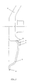
- Figure 3 shows a sectional view axial for a preferred embodiment of the device sealing according to the present invention.
- Figure 1 shows the low compressor pressure (or booster) coupled to the blower in the case a turbojet engine.
- the compressor is consisting of a drum 2 supporting the stages of blades primary flow or rotor stages and which rotates relative to the fixed stator part which supports the rectifier stages.
- the drum 2 is extended on the opposite side of the disc 1 by a flexible flange 4, playing a spring role and which expands under the effect of centrifugal forces to which the drum is subjected.
- the end of this flange is dimensioned at a fixed diameter.
- the gasket 5 is bolted to this flange 4 and has a curved portion 6 in contact with the disc 1.
- the complexity of the flange and the gasket in this first embodiment prevents any shot blasting and therefore to increase the service life of said parts.
- the seal 5 is held in place by a heel 9 made in the drum. Tightening the bearing face on this heel is achieved by the elasticity of the attached 5 itself. Sealing is ensured at a flat face of the heel 9 in axial contact with a flat face of the seal ( Figure 3, item 7). The centering of the joint and its maintenance against centrifugal forces is ensured by the radial contact of a stud with the cylindrical part of the heel ( Figure 3, item 8). Finally, the contact of the joint 5 is axial between the fan disk 1 and the part bent end 6 of joint 5.
- the size of the seal 5 can be greater than housing available after assembly. As a result, the seal is compressed during assembly ( ⁇ P ⁇ 1.5 bar), which allows avoid the use of screws and bolts and therefore the factors stress increase. However, the trials have shown that this pre-stressed contact at level of the cylindrical part of the heel is not necessary. Indeed, the joint, made for example in aluminum, expands faster than the drum under the effect centrifugal forces, so that a slight hooping.
- the seal according to the invention is made of a light and inexpensive metallic material easily formable. It thus has the advantage of being achievable in aluminum, whereas previously we would use steel or titanium (Exhibit CF1). Its module de Young is weak. Under the drive of the disc of blowing, it expands at least as fast as the drum. There is no loss of centering or sealing, which prevents the part from moving and being quickly destroyed.
Landscapes
- Engineering & Computer Science (AREA)
- General Engineering & Computer Science (AREA)
- Mechanical Engineering (AREA)
- Structures Of Non-Positive Displacement Pumps (AREA)
- Gasket Seals (AREA)
Description
- l'appui du joint sur le tambour via un simple talon ;
- l'absence de visserie pour maintenir le joint.
- des sollicitations moindres dans le joint ;
- un montage plus simple ;
- une conception simplifiée du tambour grâce à une bride plus petite nécessitant moins de matière ;
- un joint plus simple et réalisable avec des matériaux communs.
Claims (6)
- Dispositif d'étanchéité pour une enceinte pressurisée du compresseur basse pression d'un moteur de type turboréacteur, comprenant un joint (5) situé entre une bride (4) solidaire du tambour (2) supportant les aubes mobiles des étages de compression du flux primaire et le disque rotatif (1) supportant les aubes tournantes de la soufflante, l'extrémité de la bride (4) étant cotée à un diamètre fixe, caractérisé en ce que ledit joint (5) est maintenu en place, sans fixation mécanique, d'une part par contact avec un talon (9) prolongeant la bride (4) et d'autre part par contact avec ledit disque (1).
- Dispositif selon la revendication 1, caractérisé en ce que le serrage de la face d'appui du joint (5) sur ledit talon (9) est réalisé par l'élasticité du joint (5).
- Dispositif selon la revendication 1 ou 2, caractérisé en ce que l'étanchéité est assurée au niveau d'une face plane du talon (9) en contact avec une face plane du joint (7).
- Dispositif selon l'une quelconque des revendications précédentes, caractérisé en ce que le centrage du joint (5) et son maintien vis-à-vis des forces centrifuges est assuré par le contact d'un téton du joint (5) avec la partie cylindrique dudit talon (8).
- Dispositif selon l'une quelconque des revendications précédentes, caractérisé en ce que la dimension du joint (5) selon l'axe du moteur est supérieure à la longueur axiale disponible après montage, c'est à dire que le joint (5) est placé avec précontrainte.
- Dispositif selon l'une quelconque des revendications précédentes, caractérisé en ce que ledit joint (5) est réalisé en un métal ou alliage métallique léger, de préférence en aluminium.
Priority Applications (2)
| Application Number | Priority Date | Filing Date | Title |
|---|---|---|---|
| EP20010870116 EP1262695B1 (fr) | 2001-05-30 | 2001-05-30 | Joint plat d'étanchéité |
| DE2001602217 DE60102217T2 (de) | 2001-05-30 | 2001-05-30 | Dichtende Verbindungsplatte |
Applications Claiming Priority (1)
| Application Number | Priority Date | Filing Date | Title |
|---|---|---|---|
| EP20010870116 EP1262695B1 (fr) | 2001-05-30 | 2001-05-30 | Joint plat d'étanchéité |
Publications (2)
| Publication Number | Publication Date |
|---|---|
| EP1262695A1 EP1262695A1 (fr) | 2002-12-04 |
| EP1262695B1 true EP1262695B1 (fr) | 2004-03-03 |
Family
ID=8184980
Family Applications (1)
| Application Number | Title | Priority Date | Filing Date |
|---|---|---|---|
| EP20010870116 Expired - Lifetime EP1262695B1 (fr) | 2001-05-30 | 2001-05-30 | Joint plat d'étanchéité |
Country Status (2)
| Country | Link |
|---|---|
| EP (1) | EP1262695B1 (fr) |
| DE (1) | DE60102217T2 (fr) |
Families Citing this family (1)
| Publication number | Priority date | Publication date | Assignee | Title |
|---|---|---|---|---|
| DE60213621T2 (de) * | 2002-12-03 | 2007-03-08 | Techspace Aero S.A. | Dichtung für den Niederdruckverdichter eines Flugtriebwerks |
Family Cites Families (8)
| Publication number | Priority date | Publication date | Assignee | Title |
|---|---|---|---|---|
| JPS55150493A (en) * | 1979-05-10 | 1980-11-22 | Nissan Motor Co Ltd | Sealing structure for rotary regenerative heat exchanger |
| GB2102897B (en) * | 1981-07-27 | 1985-06-19 | Gen Electric | Annular seals |
| US4730832A (en) * | 1985-09-13 | 1988-03-15 | Solar Turbines Incorporated | Sealed telescopic joint and method of assembly |
| US4813692A (en) * | 1987-01-22 | 1989-03-21 | Eg&G Pressure Science, Inc. | Pressure balanced S-seal |
| US4854600A (en) * | 1987-01-22 | 1989-08-08 | Eg&G Pressure Science, Inc. | Pressure balanced metallic S-seal |
| GB2261932B (en) * | 1991-11-27 | 1995-09-06 | Rolls Royce Plc | Seal |
| US5915697A (en) * | 1997-09-22 | 1999-06-29 | General Electric Company | Flexible cloth seal assembly |
| JP3643692B2 (ja) * | 1998-03-02 | 2005-04-27 | 三菱重工業株式会社 | 回転機械のシール装置 |
-
2001
- 2001-05-30 DE DE2001602217 patent/DE60102217T2/de not_active Expired - Lifetime
- 2001-05-30 EP EP20010870116 patent/EP1262695B1/fr not_active Expired - Lifetime
Also Published As
| Publication number | Publication date |
|---|---|
| DE60102217T2 (de) | 2005-01-13 |
| EP1262695A1 (fr) | 2002-12-04 |
| DE60102217D1 (de) | 2004-04-08 |
Similar Documents
| Publication | Publication Date | Title |
|---|---|---|
| FR2865012A1 (fr) | Dispositif d'etancheite pour turbine haute-pression de turbomachine | |
| EP2870323A1 (fr) | Dispositif de joint d'etancheite de palier de turbomachine avec deux joints elastiques | |
| EP2009333A1 (fr) | Joint à brosse dynamique | |
| WO2011089355A1 (fr) | Liaison diffuseur-redresseur pour un compresseur centrifuge | |
| CA2646976A1 (fr) | Etancheite de fixation de support de palier dans une turbomachine | |
| FR3077097A1 (fr) | Dispositif de refroidissement pour une turbine d'une turbomachine | |
| FR3055678A1 (fr) | Agencement de palier axial pour un arbre d'entrainement d'un compresseur centrifuge | |
| CA2509489C (fr) | Turbomachine avec moyens de retenue axiale du rotor | |
| CA2478788A1 (fr) | Dispositif abradable sur carter de soufflante d'un moteur de turbine a gaz | |
| BE1022576B1 (fr) | Element de volute fixe et machine a fluide a volute. | |
| EP1262695A1 (fr) | Joint plat d'étanchéité | |
| FR3099801A1 (fr) | Ensemble pour une turbine de turbomachine | |
| EP1580402B1 (fr) | Turbomachine comprenant deux sous-ensembles assemblés sous contraint axiale | |
| EP1426560B1 (fr) | Joint d'étanchéité pour compresseur basse pression dans un turboréacteur | |
| FR3085187A1 (fr) | Un turbocompresseur ayant une zone de contact flexible entre un manchon de palier et une partie de compresseur fixe. | |
| FR2952964A1 (fr) | Roue mobile de turbine a gaz. | |
| FR2741142A1 (fr) | Charge generatrice de noyau ayant une tenue a l'acceleration amelioree | |
| FR3094031A1 (fr) | Ensemble pour une turbomachine | |
| FR3065481A1 (fr) | Ensemble pour turbine, notamment pour une turbomachine | |
| FR2877994A1 (fr) | Support de palier, et moteur d'aeronef equipe d'un tel support de palier. | |
| EP2075412A1 (fr) | Dispositif de fixation par boulonnage d'aubes à une virole d'étage de stator d'une turbomachine et procédé associé de fixation par boulonnage | |
| FR3115342A1 (fr) | Dispositif d'étanchéité extensible, notamment pour une soufflante à aubes à calage variable | |
| FR3085190A1 (fr) | Un turbocompresseur ayant un manchon de palier pourvu d'une reduction de section transversale | |
| FR2888877A1 (fr) | Dispositif d'amortissement des vibrations d'un rotor | |
| FR3085191A1 (fr) | Un turbocompresseur ayant un manchon de palier dote d'entailles d'extremite axiale |
Legal Events
| Date | Code | Title | Description |
|---|---|---|---|
| PUAI | Public reference made under article 153(3) epc to a published international application that has entered the european phase |
Free format text: ORIGINAL CODE: 0009012 |
|
| AK | Designated contracting states |
Kind code of ref document: A1 Designated state(s): AT BE CH CY DE DK ES FI FR GB GR IE IT LI LU MC NL PT SE TR |
|
| AX | Request for extension of the european patent |
Free format text: AL;LT;LV;MK;RO;SI |
|
| 17P | Request for examination filed |
Effective date: 20030319 |
|
| GRAH | Despatch of communication of intention to grant a patent |
Free format text: ORIGINAL CODE: EPIDOS IGRA |
|
| AKX | Designation fees paid |
Designated state(s): BE DE FR GB |
|
| GRAS | Grant fee paid |
Free format text: ORIGINAL CODE: EPIDOSNIGR3 |
|
| GRAA | (expected) grant |
Free format text: ORIGINAL CODE: 0009210 |
|
| AK | Designated contracting states |
Kind code of ref document: B1 Designated state(s): BE DE FR GB |
|
| REG | Reference to a national code |
Ref country code: GB Ref legal event code: FG4D Free format text: NOT ENGLISH |
|
| REG | Reference to a national code |
Ref country code: IE Ref legal event code: FG4D Free format text: FRENCH |
|
| REF | Corresponds to: |
Ref document number: 60102217 Country of ref document: DE Date of ref document: 20040408 Kind code of ref document: P |
|
| GBT | Gb: translation of ep patent filed (gb section 77(6)(a)/1977) |
Effective date: 20040601 |
|
| REG | Reference to a national code |
Ref country code: IE Ref legal event code: FD4D |
|
| PLBE | No opposition filed within time limit |
Free format text: ORIGINAL CODE: 0009261 |
|
| STAA | Information on the status of an ep patent application or granted ep patent |
Free format text: STATUS: NO OPPOSITION FILED WITHIN TIME LIMIT |
|
| 26N | No opposition filed |
Effective date: 20041206 |
|
| PGFP | Annual fee paid to national office [announced via postgrant information from national office to epo] |
Ref country code: GB Payment date: 20150424 Year of fee payment: 15 Ref country code: DE Payment date: 20150422 Year of fee payment: 15 |
|
| REG | Reference to a national code |
Ref country code: FR Ref legal event code: PLFP Year of fee payment: 16 |
|
| PGFP | Annual fee paid to national office [announced via postgrant information from national office to epo] |
Ref country code: FR Payment date: 20160422 Year of fee payment: 16 |
|
| REG | Reference to a national code |
Ref country code: DE Ref legal event code: R119 Ref document number: 60102217 Country of ref document: DE |
|
| GBPC | Gb: european patent ceased through non-payment of renewal fee |
Effective date: 20160530 |
|
| PG25 | Lapsed in a contracting state [announced via postgrant information from national office to epo] |
Ref country code: DE Free format text: LAPSE BECAUSE OF NON-PAYMENT OF DUE FEES Effective date: 20161201 |
|
| PG25 | Lapsed in a contracting state [announced via postgrant information from national office to epo] |
Ref country code: GB Free format text: LAPSE BECAUSE OF NON-PAYMENT OF DUE FEES Effective date: 20160530 |
|
| REG | Reference to a national code |
Ref country code: FR Ref legal event code: ST Effective date: 20180131 |
|
| PG25 | Lapsed in a contracting state [announced via postgrant information from national office to epo] |
Ref country code: FR Free format text: LAPSE BECAUSE OF NON-PAYMENT OF DUE FEES Effective date: 20170531 |
|
| PGFP | Annual fee paid to national office [announced via postgrant information from national office to epo] |
Ref country code: BE Payment date: 20180425 Year of fee payment: 18 |
|
| REG | Reference to a national code |
Ref country code: BE Ref legal event code: MM Effective date: 20190531 |
|
| PG25 | Lapsed in a contracting state [announced via postgrant information from national office to epo] |
Ref country code: BE Free format text: LAPSE BECAUSE OF NON-PAYMENT OF DUE FEES Effective date: 20190531 |