EP1262689A1 - A device for controlling an automatic and sequential gearbox - Google Patents
A device for controlling an automatic and sequential gearbox Download PDFInfo
- Publication number
- EP1262689A1 EP1262689A1 EP02011432A EP02011432A EP1262689A1 EP 1262689 A1 EP1262689 A1 EP 1262689A1 EP 02011432 A EP02011432 A EP 02011432A EP 02011432 A EP02011432 A EP 02011432A EP 1262689 A1 EP1262689 A1 EP 1262689A1
- Authority
- EP
- European Patent Office
- Prior art keywords
- lever
- selection lever
- selection
- engagement
- gearbox
- Prior art date
- Legal status (The legal status is an assumption and is not a legal conclusion. Google has not performed a legal analysis and makes no representation as to the accuracy of the status listed.)
- Granted
Links
- 230000005540 biological transmission Effects 0.000 claims abstract description 54
- 238000007373 indentation Methods 0.000 claims description 13
- 230000008878 coupling Effects 0.000 claims description 6
- 238000010168 coupling process Methods 0.000 claims description 6
- 238000005859 coupling reaction Methods 0.000 claims description 6
- 230000001419 dependent effect Effects 0.000 claims 1
- 230000008859 change Effects 0.000 description 7
- 230000005355 Hall effect Effects 0.000 description 5
- 230000000994 depressogenic effect Effects 0.000 description 3
- 230000007935 neutral effect Effects 0.000 description 2
- 230000009471 action Effects 0.000 description 1
- 238000010276 construction Methods 0.000 description 1
- 238000003745 diagnosis Methods 0.000 description 1
- 238000010586 diagram Methods 0.000 description 1
- 230000000694 effects Effects 0.000 description 1
- 238000003780 insertion Methods 0.000 description 1
- 230000037431 insertion Effects 0.000 description 1
- 230000003993 interaction Effects 0.000 description 1
- 230000007257 malfunction Effects 0.000 description 1
- 230000004048 modification Effects 0.000 description 1
- 238000012986 modification Methods 0.000 description 1
Images



Classifications
-
- F—MECHANICAL ENGINEERING; LIGHTING; HEATING; WEAPONS; BLASTING
- F16—ENGINEERING ELEMENTS AND UNITS; GENERAL MEASURES FOR PRODUCING AND MAINTAINING EFFECTIVE FUNCTIONING OF MACHINES OR INSTALLATIONS; THERMAL INSULATION IN GENERAL
- F16H—GEARING
- F16H59/00—Control inputs to control units of change-speed- or reversing-gearings for conveying rotary motion
- F16H59/02—Selector apparatus
- F16H59/0204—Selector apparatus for automatic transmissions with means for range selection and manual shifting, e.g. range selector with tiptronic
-
- F—MECHANICAL ENGINEERING; LIGHTING; HEATING; WEAPONS; BLASTING
- F16—ENGINEERING ELEMENTS AND UNITS; GENERAL MEASURES FOR PRODUCING AND MAINTAINING EFFECTIVE FUNCTIONING OF MACHINES OR INSTALLATIONS; THERMAL INSULATION IN GENERAL
- F16H—GEARING
- F16H61/00—Control functions within control units of change-speed- or reversing-gearings for conveying rotary motion ; Control of exclusively fluid gearing, friction gearing, gearings with endless flexible members or other particular types of gearing
- F16H61/24—Providing feel, e.g. to enable selection
- F16H2061/243—Cams or detent arrays for guiding and providing feel
-
- F—MECHANICAL ENGINEERING; LIGHTING; HEATING; WEAPONS; BLASTING
- F16—ENGINEERING ELEMENTS AND UNITS; GENERAL MEASURES FOR PRODUCING AND MAINTAINING EFFECTIVE FUNCTIONING OF MACHINES OR INSTALLATIONS; THERMAL INSULATION IN GENERAL
- F16H—GEARING
- F16H59/00—Control inputs to control units of change-speed- or reversing-gearings for conveying rotary motion
- F16H59/02—Selector apparatus
- F16H59/08—Range selector apparatus
- F16H59/10—Range selector apparatus comprising levers
- F16H59/105—Range selector apparatus comprising levers consisting of electrical switches or sensors
-
- F—MECHANICAL ENGINEERING; LIGHTING; HEATING; WEAPONS; BLASTING
- F16—ENGINEERING ELEMENTS AND UNITS; GENERAL MEASURES FOR PRODUCING AND MAINTAINING EFFECTIVE FUNCTIONING OF MACHINES OR INSTALLATIONS; THERMAL INSULATION IN GENERAL
- F16H—GEARING
- F16H61/00—Control functions within control units of change-speed- or reversing-gearings for conveying rotary motion ; Control of exclusively fluid gearing, friction gearing, gearings with endless flexible members or other particular types of gearing
- F16H61/24—Providing feel, e.g. to enable selection
Definitions
- the present invention relates to a device for controlling a motor-vehicle gearbox which can operate alternatively in automatic or sequential mode, as specified in the preamble to Claim 1.
- Gearboxes which can operate both in conventional automatic mode and in sequential mode are currently being promoted with success, not only in high-level motorcars, but also in those of a lower level.
- the driver of the motor vehicle can operate a gear-selection lever by moving it between various engagement positions, which are generally the following five positions:
- the gear-selection lever can be moved between the following three positions:
- the gear lever is kept at rest in the central "0" position; movement of the lever towards the "+” position brings about an upward change to a gear or ratio immediately higher than that which is currently engaged, whereas movement to the "-" position brings about a downward change by one gear.
- the gearbox is usually operated in a servo-assisted manner under the control of an electronic control system which receives appropriate consent signals when the movement of the selection lever towards one of the two active positions "+" and "-" is detected.
- Figure 6 of the appended drawings shows a typical example of the arrangement of the gears on a selection-lever positioning grid for automatic/sequential gearbox control.
- the gear-selection lever can pivot in a first, substantially longitudinal plane ⁇ A in order to move, alternatively, into one of the above-mentioned five engagement positions corresponding to the automatic mode of operation, and in a second plane ⁇ S , which is inclined relative to the plane ⁇ A , for the engagement of the gears in the sequential mode of operation. Movement from one operating plane to the other is permitted between the positions "D" (normal driving in automatic mode) and "0" (the rest position in sequential mode) by pivoting of the gear lever in a transverse plane.
- the aim of the present invention is to provide a device for controlling a motor-vehicle gearbox which can operate alternatively in automatic or sequential mode, which device is structurally simple, has small dimensions, ensures precise and reliable operation, and permits a change from one operating condition to the other without jamming, and in any driving condition.
- a device for controlling a motor-vehicle gearbox which can operate alternatively in automatic or sequential mode, comprising:
- a device according to the invention, generally indicated 1, for controlling an automatic/sequential gearbox comprises, basically, the following components:
- the fixed body 2 which is intended to house the various components of the control device 1 in order to permit their correct relative positions and to ensure their correct operation, is securely fitted in the vehicle by conventional fixing means inserted through holes 9.
- two substantially parallel guide tracks 13 and 14 are formed in the lower portion of the fixed body 2 for guiding the pivoting movement of the selection lever 4 in plane ⁇ A for operation in automatic mode and in plane ⁇ S for operation in sequential mode respectively.
- these planes are inclined to one another transversely and are oriented in a manner such that the pivoting of the selection lever 4 in each of them defines a path which, when viewed in projection onto a horizontal plane, runs substantially longitudinally.
- both of the guide tracks 13 and 14 have circular arc-shaped profiles with their centres on a transverse geometrical axis T which is fixed relative to the movable body 3, and about which the selection lever 4 can pivot ( Figure 2).
- Figure 3 which shows a section through the control device 1, taken in the plane ⁇ A , a plurality of indentations 15 are formed in a sliding surface 13a of the track 13 and are spaced apart evenly along the circular arc-shaped profile to define the engagement positions of the selection lever 4 for operation in automatic mode.
- the reference numerals of the indentations 15 are distinguished from one another by the addition of the subscripts P, R, N, D, L, each of which identifies the homonymous engagement position of the gearbox in the automatic mode of operation.
- the axis of pivoting L of the movable body 3 is oriented in the longitudinal plane ⁇ A in a manner such as to be perpendicular to the selection lever 4 when the lever is in the engagement position D, that is, in the indentation 15 D , along the guide track 13.
- a single indentation 16 is formed on a sliding surface 14a of the guide track 14 ( Figure 4) and defines the rest position "0" for the selection lever 4 in the sequential mode of operation.
- the guide tracks 13 and 14 also have lateral guide surfaces 13b and 14b, respectively, and are separated from one another by an intermediate wall 17 ( Figure 2).
- a transverse passageway 18, visible in Figure 4 is formed in this wall aligned with the positions "D" (automatic operation) and "0" (sequential operation) to allow the selection lever 4 to move from one guide track to the other when the driver switches the mode of operation of the gearbox by moving the lever sideways, thus causing the movable body 3 and the selection lever 4 to pivot together about the axis L.
- the fixed body 2 also has, laterally, on the side on which the plane ⁇ A is disposed, a support 19 with a transverse horizontal axis for the mounting of a substantially cylindrical, shaft-like portion 20 secured to or integral with the transmission lever 5.
- the movable body 3 which supports the selection lever 4 has a hollow structure extending vertically, open at the top and at the bottom so that the lever can extend through it, and having a rectangular cross-section with two parallel longitudinal walls 21 connected by two parallel transverse walls 22.
- holes 24 are formed in the transverse walls 22 of the body 3 for the insertion of the support pins 12 which engage in the seats 11 of the fixed body 2 for allowing the body 3 to pivot about the axis L during the switch between one mode of operation and the other.
- a portion 25 in the form of a transverse pin secured to the selection lever 4 is carried in the region of the lower edges of the longitudinal walls 21, in a substantially central position ( Figure 2).
- the pin 25 is mounted for rotating about its own axis in a cylindrical seat 26 an upper portion of which is formed in the lower edges of the longitudinal walls 21 of the body 3 and a lower portion of which is in a bracket 27 fixed to these walls by means of scraws 28 or other connecting members (Figure 3).
- the longitudinal walls 21 of the movable body 3 also have a pair of suitably-shaped slots 29 in which a mechanical restraint pin 30 can move, as explained in the following part of the description.
- the longitudinal wall 21 of the movable body 3 which faces towards the operating plane ⁇ S has an outwardly-projecting bracket 31 for the fixing of the electromagnet 6.
- the latter is arranged to move a plate 32 transversely between a first, extended position ( Figure 2) in which the plate blocks the movement of the mechanical restraint pin 30 and a second, retracted position which permits the movement of the pin 30 in the pair of slots 29.
- the selection lever 4 which is supported by the movable body 3 by means of the transverse pin 25 for pivoting about the axis T, comprises, basically:
- a rod 35 arranged for sliding along an inner cylindrical surface 36 of the cylindrical tube 33 has:
- a resilient element 37 such as a conventional helical torsion spring, interposed between the pin 25 of the selection lever 4 and the lower end 35b of the rod 35, the rod 35 is kept, at rest, in an upper travel-limit position defined by the abutment of the mechanical restraint pin 30 against the upper profiles of the slots 29 ( Figure 2).
- the fulcrum pin 25 Fixed firmly to the selection lever 4 in the vicinity of the lower end of the tube 33 is the fulcrum pin 25 which can be supported rotatably in the seat 26 of the movable body 3.
- An engagement face tooth 40 formed on the face of the pin 25 which faces towards the transmission lever 5 can engage a diametral groove 41 formed in the laterally inner face of the shaft-like portion 20 of the lever 5 when the selection lever 4 is disposed in the plane ⁇ A for the operation of the gearbox in automatic mode ( Figures 2 and 4) so as to transmit the pivoting movement of the selection lever about its own axis T to the transmission lever.
- the lower element 34 of the selection lever 4 comprises:
- a pawl 46 which has a spherical head 47 and is loaded by a spring 48, is arranged for sliding axially in the cavity 45 and can engage the indentations 15 of the track 13 (operation in automatic mode) or the indentation 16 of the track 14 (operation in sequential mode) to ensure that the selection lever 4 is located correctly in the selected position.
- a magnet 49 is fitted in one of the lateral surfaces 44 of the lower element 34 of the selection lever 4, on the side facing the electromagnet 6 and the printed circuit 7.
- the magnet 49 is arranged at a height such as not to interfere with the lateral guide surfaces 13b, 14b of the guide tracks 13, 14 and to face Hall-effect sensors 50 mounted on the printed circuit 7 when the lever 4 is moved in the plane ⁇ S for the operation of the gearbox in sequential mode ( Figure 5).
- the movement of the selection lever 4 from the rest position "0" to the position "+” or to the position "-” can thus be detected by the sensors 50, cooperating with the magnet 49, in order to send consent signals for the engagement of a higher or lower gear, respectively, to an electronic control unit of the gearbox.
- a resilient device 51 is mounted on the lower element 34 of the selection lever 4, on the side transversely remote from the magnet 49 and, when the lever 4 is moved sideways into the operating plane ⁇ S for operation in sequential mode, can interact with two catch projections 52 arranged facing one another longitudinally on the fixed body 2 to ensure the return of the selection lever from one of the two active positions "+” and "-" to the rest position "0", after each operation.
- transverse arms 53 are fixed to the cylindrical tube 33 of the selection lever 4, above the movable body 3, for supporting a first longitudinal pin 54 for the articulation of a head 55 of the connecting rod 8 ( Figure 1).
- the cylindrical shaft-like portion 20 of the transmission lever 5 is mounted for rotating on the support 19 about a horizontal transverse axis which, in the operation of the gearbox in automatic mode, that is, when the selection lever 4 is in the plane ⁇ A , is substantially coaxial with the pin 25 of that lever (axis T).
- the shaft 20 can also be moved axially, that is, in a transverse direction, between
- the cylindrical shaft 20 of the transmission lever 5 has a tooth 58 formed on its lateral surface for engaging in a transverse slot 59 of the support 19 (clearly visible in Figure 4) as a result of the movement of the lever 5 from position A to position S.
- the shaft 20 also has an upper bracket-like element 60 which projects from the support 19 to engage a second longitudinal pin 61 to which a lower end 62 of the connecting rod 8 is articulated ( Figure 1).
- the transmission lever 5 When the selection lever 4 is in the plane ⁇ A for operation in automatic mode ( Figures 2 and 4), the transmission lever 5 is kept in position A so that the engagement face tooth 40 of the lever 4 engages the diametral groove 41 of the lever 5 in order to transmit the pivoting movement about the transverse axis T directly to the lever 5 when the driver performs a gear change.
- the controls imparted to the selection lever 4 are in fact transmitted to the gearbox not by means of the flexible cable connected to the transmission lever 5 but under the control of an electronic unit which can receive any consent signals sent by the Hall-effect sensors 50.
- the articulated ends 55 and 62 of the connecting rod are mounted on the respective longitudinal pins 54 and 61 with sufficient clearance.
- one of the two articulation pins may be replaced by a swivel coupling (such as a ball joint).
- Movement of the transmission lever 5 to the position S also brings about engagement of the tooth 58 of the shaft-like portion 20 in the slot 59 formed in the support 19 and hence locking of the pivoting of the lever 5 itself.
- the alignment between the engagement tooth 40 of the selection lever 4 and the groove 41 of the transmission lever 5 is thus maintained throughout the operation of the gearbox in sequential mode so that, when the user decides to change to automatic mode, he simply has to move the lever 4 sideways, without worrying about re-establishing the engagement between the tooth 40 and the groove 41.
- the selection lever 4 When the motor vehicle is stationary with the engine switched off, the selection lever 4 is necessarily disposed in position "P" (parking); this is in fact an obligatory initial condition imposed by a control system of the vehicle which does not allow the ignition key to be removed from the motor vehicle if the selection lever 4 is not in the above-mentioned position.
- the slot 29 in the movable body 3 is generally shaped in a manner such that, by cooperating with the pin 30, it mechanically prevents movement of the selection lever 4 from the position "N” to the position “R”, from “R” to “P”, and from “P” to “R”, unless the push-button 35a of the rod 35 is depressed.
- the biasing spring 37 After the driver has completed the movement of the lever 4 to the desired position, the biasing spring 37 returns the mechanical restraint pin to the locking position. In all other operating conditions, however, the selection lever 4 is free to be moved from one position to another without the need to act on the push-button 35a of the rod 35.
- the connecting rod 8 urges the transmission lever 5 transversely outwardly to the position S.
- the consequent disengagement of the face tooth 40 of the fulcrum pin 25 from the diametral groove 41 of the shaft 20 causes the selection lever 4 and the transmission lever 5 to be rotationally uncoupled, thus preventing operation of the gearbox in automatic mode.
- the magnet 49 fitted in the lower element 34 of the selection lever 4 is moved in front of the Hall-effect sensors 50 mounted on the printed circuit 7, enabling changes in the position of the lever 4 to be detected during the operation of the gearbox in sequential mode.
- the selection lever 4 can be moved from the rest position "0" forwards (towards the "+” position) or backwards (towards the "-” position) in order to engage a higher or lower gear, respectively.
- the Hall-effect sensors 50 detect the movement of the selection lever 4 from the rest position "0" to one of the two active positions “+” or “-” and send a corresponding consent signal to the gearbox-control system for the execution of the shift.
Landscapes
- Engineering & Computer Science (AREA)
- General Engineering & Computer Science (AREA)
- Mechanical Engineering (AREA)
- Arrangement Or Mounting Of Control Devices For Change-Speed Gearing (AREA)
- Selective Calling Equipment (AREA)
- Gear-Shifting Mechanisms (AREA)
- Control Of Transmission Device (AREA)
Abstract
Description
- The present invention relates to a device for controlling a motor-vehicle gearbox which can operate alternatively in automatic or sequential mode, as specified in the preamble to Claim 1.
- Gearboxes which can operate both in conventional automatic mode and in sequential mode are currently being promoted with success, not only in high-level motorcars, but also in those of a lower level. As is known, in the first case, the driver of the motor vehicle can operate a gear-selection lever by moving it between various engagement positions, which are generally the following five positions:
- "P" (parking): for parking and when the vehicle is stationary;
- "R" (reverse): for driving backwards;
- "N" (neutral): the neutral position;
- "D" (drive): for normal driving, and
- "L" (low): for driving on steep gradients.
- In the sequential mode of operation, on the other hand, the gear-selection lever can be moved between the following three positions:
- "+": to change to a higher gear;
- "0": the central, rest position, and
- "-": to change to a lower gear.
- In this case, the gear lever is kept at rest in the central "0" position; movement of the lever towards the "+" position brings about an upward change to a gear or ratio immediately higher than that which is currently engaged, whereas movement to the "-" position brings about a downward change by one gear. The gearbox is usually operated in a servo-assisted manner under the control of an electronic control system which receives appropriate consent signals when the movement of the selection lever towards one of the two active positions "+" and "-" is detected.
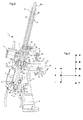
- Figure 6 of the appended drawings shows a typical example of the arrangement of the gears on a selection-lever positioning grid for automatic/sequential gearbox control.
- The gear-selection lever can pivot in a first, substantially longitudinal plane πA in order to move, alternatively, into one of the above-mentioned five engagement positions corresponding to the automatic mode of operation, and in a second plane πS, which is inclined relative to the plane πA, for the engagement of the gears in the sequential mode of operation. Movement from one operating plane to the other is permitted between the positions "D" (normal driving in automatic mode) and "0" (the rest position in sequential mode) by pivoting of the gear lever in a transverse plane.
- The aim of the present invention is to provide a device for controlling a motor-vehicle gearbox which can operate alternatively in automatic or sequential mode, which device is structurally simple, has small dimensions, ensures precise and reliable operation, and permits a change from one operating condition to the other without jamming, and in any driving condition.
- This and other aims are achieved in full, according to the invention, by means of a device for controlling a motor-vehicle gearbox which can operate alternatively in automatic or sequential mode, comprising:
- a selection lever capable of pivoting:
- about a first axis in order to move between a first plane for the operation of the gearbox in automatic mode and a second plane for the operation of the gearbox in sequential mode, and
- about a second axis in order to move between a plurality of engagement positions in one of the first and second planes,
- a transmission lever for connection to a control member on
the gearbox by flexible transmission means and which can be
moved between
- a first position, when the selection lever lies in the first plane, in which position the transmission lever is coupled rotationally with the selection lever in order to pivot about the second axis together therewith and thus to control the operation of the gearbox in automatic mode, and
- a second position, when the selection lever lies in the second plane, in which position the transmission lever is rotationally disconnected from the selection lever to ensure operation of the gearbox in sequential mode, and
- articulation means interposed between the selection and transmission levers for moving the transmission lever between the first and second positions as a result of the pivoting of the selection lever about the first axis between the first and second planes.
- A preferred but non-limiting embodiment of the invention will be described below with reference to the appended drawings, in which:
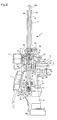
- Figure 1 is a general perspective view of a device according to the invention for controlling an automatic/sequential gearbox, with the selection lever in the rest position "0" of the sequential mode of operation,
- Figure 2 is a cross-section through the control device of Figure 1 with the selection lever in the idle position "N" of the automatic mode of operation,
- Figure 3 is a longitudinal section through the control device of Figure 1 with the selection lever in the idle position "N" of the automatic mode of operation,
- Figure 4 is a cross-section through the control device of Figure 1 with the selection lever in the normal driving position "D" of the automatic mode of operation,
- Figure 5 is a cross-section through the control device of Figure 1 with the selection lever in the rest position "0" of the sequential mode of operation, and
- Figure 6 is a diagram illustrating the arrangement of the gears on a selection-lever positioning grid of an automatic/sequential gearbox.
-
- In the description and in the appended claims, terms such as "longitudinal", "transverse", and "lateral" are intended to refer to the condition of mounting on the motor vehicle.
- With reference to Figure 1, a device according to the invention, generally indicated 1, for controlling an automatic/sequential gearbox comprises, basically, the following components:
- a
fixed support body 2, - a
movable body 3, - a selection lever 4,
- a
transmission lever 5, - an
electromagnet 6, - a printed
circuit 7, and -
a connecting rod 8. - The
fixed body 2, which is intended to house the various components of the control device 1 in order to permit their correct relative positions and to ensure their correct operation, is securely fitted in the vehicle by conventional fixing means inserted throughholes 9. - Longitudinally spaced-apart and aligned
seats 11 are formed in twoupper appendages 10 of thefixed body 2 andrespective pins 12 for supporting the movable body 3 (Figures 1 and 3) are inserted therein so as to be rotatable about an axis L lying in a longitudinal plane. As will be explained in greater detail below, pivoting of themovable body 3 and of the selection lever 4 supported thereby brings about movement of this lever between the above-mentioned pivoting planes πA and πS and hence the switching of the gearbox between the automatic and sequential modes of operation. - With reference to Figure 2, two substantially
parallel guide tracks fixed body 2 for guiding the pivoting movement of the selection lever 4 in plane πA for operation in automatic mode and in plane πS for operation in sequential mode respectively. As already explained in the introductory portion, these planes are inclined to one another transversely and are oriented in a manner such that the pivoting of the selection lever 4 in each of them defines a path which, when viewed in projection onto a horizontal plane, runs substantially longitudinally. - In longitudinal section, both of the
guide tracks movable body 3, and about which the selection lever 4 can pivot (Figure 2). - As can clearly be seen in Figure 3, which shows a section through the control device 1, taken in the plane πA, a plurality of
indentations 15 are formed in asliding surface 13a of thetrack 13 and are spaced apart evenly along the circular arc-shaped profile to define the engagement positions of the selection lever 4 for operation in automatic mode. In particular, proceeding anticlockwise along the track 13 (with respect to the observer of Figure 3), the reference numerals of theindentations 15 are distinguished from one another by the addition of the subscripts P, R, N, D, L, each of which identifies the homonymous engagement position of the gearbox in the automatic mode of operation. - It will also be noted, still with reference to Figure 3, that the axis of pivoting L of the
movable body 3 is oriented in the longitudinal plane πA in a manner such as to be perpendicular to the selection lever 4 when the lever is in the engagement position D, that is, in theindentation 15D, along theguide track 13. - A
single indentation 16 is formed on a slidingsurface 14a of the guide track 14 (Figure 4) and defines the rest position "0" for the selection lever 4 in the sequential mode of operation. - The
guide tracks lateral guide surfaces movable body 3 and the selection lever 4 to pivot together about the axis L. - The
fixed body 2 also has, laterally, on the side on which the plane πA is disposed, asupport 19 with a transverse horizontal axis for the mounting of a substantially cylindrical, shaft-like portion 20 secured to or integral with thetransmission lever 5. - The
movable body 3 which supports the selection lever 4 has a hollow structure extending vertically, open at the top and at the bottom so that the lever can extend through it, and having a rectangular cross-section with two parallellongitudinal walls 21 connected by two paralleltransverse walls 22. - With reference to Figure 3 in particular,
holes 24 are formed in thetransverse walls 22 of thebody 3 for the insertion of thesupport pins 12 which engage in theseats 11 of thefixed body 2 for allowing thebody 3 to pivot about the axis L during the switch between one mode of operation and the other. Aportion 25 in the form of a transverse pin secured to the selection lever 4 is carried in the region of the lower edges of thelongitudinal walls 21, in a substantially central position (Figure 2). - The
pin 25 is mounted for rotating about its own axis in acylindrical seat 26 an upper portion of which is formed in the lower edges of thelongitudinal walls 21 of thebody 3 and a lower portion of which is in abracket 27 fixed to these walls by means ofscraws 28 or other connecting members (Figure 3). - The
longitudinal walls 21 of themovable body 3 also have a pair of suitably-shaped slots 29 in which amechanical restraint pin 30 can move, as explained in the following part of the description. - Finally, the
longitudinal wall 21 of themovable body 3 which faces towards the operating plane πS has an outwardly-projectingbracket 31 for the fixing of theelectromagnet 6. The latter is arranged to move aplate 32 transversely between a first, extended position (Figure 2) in which the plate blocks the movement of themechanical restraint pin 30 and a second, retracted position which permits the movement of thepin 30 in the pair ofslots 29. - With reference to Figure 2 in particular, the selection lever 4, which is supported by the
movable body 3 by means of thetransverse pin 25 for pivoting about the axis T, comprises, basically: - a
cylindrical tube 33 projecting from the top of thebody 3 for operation by the driver of the motor vehicle, and - a
lower element 34 which is fitted in thetube 33 below thetransverse pin 25 and can engage theguide tracks fixed body 2. - A
rod 35 arranged for sliding along an innercylindrical surface 36 of thecylindrical tube 33 has: - an
upper end portion 35a in the form of a push-button which projects from the top of thetube 33 in order to be depressed by the driver of the motor vehicle in order to release the mechanical restraint, and - a
lower end portion 35b in which themechanical restraint pin 30 is fitted transversely, the pin passing through a pair ofopenings 39 formed vertically in thetube 33, in order to engage theslots 29 of themovable body 3. - As a result of the upward biasing force exerted by a
resilient element 37, such as a conventional helical torsion spring, interposed between thepin 25 of the selection lever 4 and thelower end 35b of therod 35, therod 35 is kept, at rest, in an upper travel-limit position defined by the abutment of themechanical restraint pin 30 against the upper profiles of the slots 29 (Figure 2). - Fixed firmly to the selection lever 4 in the vicinity of the lower end of the
tube 33 is thefulcrum pin 25 which can be supported rotatably in theseat 26 of themovable body 3. Anengagement face tooth 40 formed on the face of thepin 25 which faces towards thetransmission lever 5 can engage adiametral groove 41 formed in the laterally inner face of the shaft-like portion 20 of thelever 5 when the selection lever 4 is disposed in the plane πA for the operation of the gearbox in automatic mode (Figures 2 and 4) so as to transmit the pivoting movement of the selection lever about its own axis T to the transmission lever. - As can be seen in Figure 2, the
lower element 34 of the selection lever 4 comprises: - an upper
cylindrical portion 42 fitted in the bottom of thetube 33, and - a
lower portion 43 which has two parallel, longitudinal,outer surfaces 44, which can slide along the lateral surfaces 13b and 14b of the guide tracks 13 and 14, and aninternal cavity 45, which is open at the bottom. - A
pawl 46, which has a spherical head 47 and is loaded by aspring 48, is arranged for sliding axially in thecavity 45 and can engage theindentations 15 of the track 13 (operation in automatic mode) or theindentation 16 of the track 14 (operation in sequential mode) to ensure that the selection lever 4 is located correctly in the selected position. - A
magnet 49 is fitted in one of the lateral surfaces 44 of thelower element 34 of the selection lever 4, on the side facing theelectromagnet 6 and the printedcircuit 7. Themagnet 49 is arranged at a height such as not to interfere with the lateral guide surfaces 13b, 14b of the guide tracks 13, 14 and to face Hall-effect sensors 50 mounted on the printedcircuit 7 when the lever 4 is moved in the plane πS for the operation of the gearbox in sequential mode (Figure 5). The movement of the selection lever 4 from the rest position "0" to the position "+" or to the position "-" can thus be detected by thesensors 50, cooperating with themagnet 49, in order to send consent signals for the engagement of a higher or lower gear, respectively, to an electronic control unit of the gearbox. - With further reference to Figure 5, a
resilient device 51 is mounted on thelower element 34 of the selection lever 4, on the side transversely remote from themagnet 49 and, when the lever 4 is moved sideways into the operating plane πS for operation in sequential mode, can interact with two catch projections 52 arranged facing one another longitudinally on the fixedbody 2 to ensure the return of the selection lever from one of the two active positions "+" and "-" to the rest position "0", after each operation. - Finally, two
transverse arms 53 are fixed to thecylindrical tube 33 of the selection lever 4, above themovable body 3, for supporting a firstlongitudinal pin 54 for the articulation of ahead 55 of the connecting rod 8 (Figure 1). - As mentioned above, the cylindrical shaft-
like portion 20 of thetransmission lever 5 is mounted for rotating on thesupport 19 about a horizontal transverse axis which, in the operation of the gearbox in automatic mode, that is, when the selection lever 4 is in the plane πA, is substantially coaxial with thepin 25 of that lever (axis T). - The
shaft 20 can also be moved axially, that is, in a transverse direction, between - a first, transversely inner position A, shown in Figure 4,
in which the
shaft 20 is coupled rotationally with the selection lever 4 when the lever is disposed in the plane πA for the automatic mode of operation, in order to operate a control member on the gearbox by means of a flexible cable (not shown) connected to oneend 56 of anarm 57 of thetransmission lever 5; and - a second, transversely outer position S, shown in Figure 5,
in which the
shaft 20 is rotationally uncoupled from the selection lever 4 when the lever is in the plane πS for operation in sequential mode, in order to ensure sequential operation of the gearbox. -
- In addition to the
diametral groove 41 on its face facing towards the selection lever 4, thecylindrical shaft 20 of thetransmission lever 5 has atooth 58 formed on its lateral surface for engaging in atransverse slot 59 of the support 19 (clearly visible in Figure 4) as a result of the movement of thelever 5 from position A to position S. Theshaft 20 also has an upper bracket-like element 60 which projects from thesupport 19 to engage a secondlongitudinal pin 61 to which alower end 62 of the connectingrod 8 is articulated (Figure 1). - When the selection lever 4 is in the plane πA for operation in automatic mode (Figures 2 and 4), the
transmission lever 5 is kept in position A so that theengagement face tooth 40 of the lever 4 engages thediametral groove 41 of thelever 5 in order to transmit the pivoting movement about the transverse axis T directly to thelever 5 when the driver performs a gear change. - When the selection lever 4 is moved sideways in order to pivot in the plane πS for operation in sequential mode (Figure 5), however, the
shaft 20 of thetransmission lever 5 is moved by means of the connectingrod 8, to the position S in which theface tooth 40 of the selection lever 4 is disengaged from thediametral groove 41 of thelever 5. The rotational uncoupling of the two levers ensures that the movements imparted to the selection lever 4 from the rest position "0" towards the two active positions "+" and "-" by the driver in the sequential mode of operation are not transmitted to thetransmission lever 5 and do not therefore bring about any action on the flexible cable which controls the automatic operation of the gearbox. - In the sequential mode of operation, the controls imparted to the selection lever 4 are in fact transmitted to the gearbox not by means of the flexible cable connected to the
transmission lever 5 but under the control of an electronic unit which can receive any consent signals sent by the Hall-effect sensors 50. In this operating condition, to prevent the pivoting movement of the selection lever 4 in the plane πS from being transmitted to thetransmission lever 5 by means of the connectingrod 8, the articulated ends 55 and 62 of the connecting rod are mounted on the respectivelongitudinal pins - Movement of the
transmission lever 5 to the position S also brings about engagement of thetooth 58 of the shaft-like portion 20 in theslot 59 formed in thesupport 19 and hence locking of the pivoting of thelever 5 itself. The alignment between theengagement tooth 40 of the selection lever 4 and thegroove 41 of thetransmission lever 5 is thus maintained throughout the operation of the gearbox in sequential mode so that, when the user decides to change to automatic mode, he simply has to move the lever 4 sideways, without worrying about re-establishing the engagement between thetooth 40 and thegroove 41. - The operation of the device 1 according to the present invention for controlling an automatic/sequential gearbox will now be described.
- When the motor vehicle is stationary with the engine switched off, the selection lever 4 is necessarily disposed in position "P" (parking); this is in fact an obligatory initial condition imposed by a control system of the vehicle which does not allow the ignition key to be removed from the motor vehicle if the selection lever 4 is not in the above-mentioned position.
- After the vehicle has been started, in order to move the selection lever 4, it is necessary to release the electrical and mechanical restraints which keep it locked in the initial "P" position. With reference to Figure 3, it can in fact been seen that, if the lever 4 is in the position "P" defined by the
indentation 15P in the slidingsurface 13a of theguide track 13, thespring 37 keeps themechanical restraint pin 30 in abutment with the end of aportion 29a of theslot 29 in themovable body 3, which portion is aligned with the lever 4 and is closed at the top. In this condition, disengagement of thepin 30 from theslot portion 29a is prevented by theplate 32 of the electromagnet 6 (Figure 2); this locking effect is commonly known as electrical restraint. - In order to move the
plate 32 of theelectromagnet 6 to the retracted position to release the electrical restraint, it suffices for the driver to depress the brake pedal. At this point, the mechanical restraint can also be released; in fact, if the push-button 35a of therod 35 is depressed, therod 35 translates downwards along thecylindrical surface 36 of thetube 33, against the biasing force of thespring 37, dragging themechanical restraint pin 30 along with it as far as a lower travel-limit position outside theportion 29a of theslot 29. - The
slot 29 in themovable body 3 is generally shaped in a manner such that, by cooperating with thepin 30, it mechanically prevents movement of the selection lever 4 from the position "N" to the position "R", from "R" to "P", and from "P" to "R", unless the push-button 35a of therod 35 is depressed. After the driver has completed the movement of the lever 4 to the desired position, the biasingspring 37 returns the mechanical restraint pin to the locking position. In all other operating conditions, however, the selection lever 4 is free to be moved from one position to another without the need to act on the push-button 35a of therod 35. - The pivoting of the selection lever 4 about the transverse axis T between the various engagement positions along the
guide track 13 causes the transmission lever 5 (which is in position A) to pivot therewith, by virtue of the coupling between theface tooth 40 and thediametral groove 41, and thus brings about operation of the control member on the gearbox by means of the flexible cable connected to theend 56 of thelever 5. - The presence of the
indentations 15 in which the spherical head 47 of the selection lever 4 can engage along the slidingsurface 13a of theguide track 13, enables the user to feel that the engagement position has been reached and to be sure that this position will be maintained (also by virtue of the mechanical restraint system). - Switching from the automatic mode of operation to the sequential mode is permitted solely when the selection lever 4 is in the position "D". If, starting from this position, the driver moves the upper end of the lever 4 sideways, the
movable body 3 is pivoted about the axis L until the lever is brought into the plane πS for the sequential mode of operation, in the rest position "0". - As a result of the pivoting of the selection lever 4 about the axis L, the connecting
rod 8 urges thetransmission lever 5 transversely outwardly to the position S. The consequent disengagement of theface tooth 40 of thefulcrum pin 25 from thediametral groove 41 of theshaft 20 causes the selection lever 4 and thetransmission lever 5 to be rotationally uncoupled, thus preventing operation of the gearbox in automatic mode. Moreover, themagnet 49 fitted in thelower element 34 of the selection lever 4 is moved in front of the Hall-effect sensors 50 mounted on the printedcircuit 7, enabling changes in the position of the lever 4 to be detected during the operation of the gearbox in sequential mode. - As already mentioned in the introductory portion of the description, in the sequential mode of operation, the selection lever 4 can be moved from the rest position "0" forwards (towards the "+" position) or backwards (towards the "-" position) in order to engage a higher or lower gear, respectively. Once the "+" position or the "-" position has been reached, when the lever 4 is released, it returns to the rest position "0" as a result of the interaction between the
resilient device 51 mounted on thelower element 34 of the lever and one of the catch projections 52 inside the fixedbody 2. - The Hall-
effect sensors 50 detect the movement of the selection lever 4 from the rest position "0" to one of the two active positions "+" or "-" and send a corresponding consent signal to the gearbox-control system for the execution of the shift. - In order to return to the automatic mode of operation, it suffices for the driver to move the selection lever 4 sideways from the position "0" on the
guide track 14 to the position "D" on theguide track 13. Thetransmission lever 5 is thus shifted transversely by means of the connectingrod 8 from the position S to the position A, re-establishing the rotational coupling with the selection lever 4, by means of theface tooth 40. At the same time, themagnet 49 moves away from thesensors 50 which therefore no longer transmit any consent signals. The pivoting of the selection lever 4 about the axis L once again brings about pivoting of thetransmission lever 5 therewith and hence the transmission of the controls by means of the flexible cable connected thereto. - As will be clear from the foregoing description, the use of a control device according to the invention achieves a series of advantages which can be summarized in the following points:
- small dimensions of the device,
- structural simplicity of the device and hence high reliability and ease of diagnosis and intervention in the event of a malfunction or breakage,
- direct operation of the selection lever on the flexible cable in the automatic mode of operation, by virtue of the rotational coupling of the selection lever with the transmission lever by means of the face-tooth engagement, and accordingly minimization of errors due to coupling tolerances,
- precise control of the transverse distance of the magnet on the selection lever from the Hall-effect sensors on the printed circuit, by virtue of the guide track in which the lower end of the selection lever is caused to pivot in the sequential mode of operation, and
- possibility to vary the direction of output of the flexible cable to allow the device to be fitted either on the dashboard or on the floor of the motor vehicle, simply by modification of the direction of the arm of the transmission lever.
- Naturally, the principle of the invention remaining the same, the forms of embodiment and details of construction may be varied widely with respect to those described and illustrated purely by way of non-limiting example, without thereby departing from the scope of the invention as defined in the appended claims.
Claims (18)
- A device (1) for controlling a motor-vehicle gearbox which can operate alternatively in automatic or sequential mode, comprising:a selection lever (4) which can pivotabout a first axis (L) in order to move between a first plane (πA) for the operation of the gearbox in automatic mode and a second plane (πS) for the operation of the gearbox in sequential mode, andabout a second axis (T) in order to move between a plurality of engagement positions (P, R, N, D, L; +, 0, -) in one of the first and second planes (πA, πS),a transmission lever (5) which can be connected to a control member on the gearbox by flexible transmission means and which can be moved between:a first position (A), when the selection lever (4) lies in the first plane (πA), in which position the transmission lever (5) is coupled rotationally with the selection lever (4) in order to pivot about the second axis (T) together therewith and thus to control the operation of the gearbox in automatic mode, anda second position (S), when the selection lever (4) lies in the second plane (πS), in which position the transmission lever (5) is rotationally uncoupled from the selection lever (4) to ensure operation of the gearbox in sequential mode, andarticulation means (8) interposed between the selection lever (4) and the transmission lever (5) for moving the transmission lever (5) between the first and second positions (A, S) as a result of the pivoting of the selection lever (4) about the first axis (L) between the first and second planes (πA, πS).
- A device according to Claim 1, characterized in that it further comprises a first, fixed support body (2) and a second, movable body (3), the second body (3) being supported in a pivotable manner (11, 12) by the first body (2) in order to pivot about the first axis (L), the selection lever (4) being supported (25, 26) by the second body (3) in a manner such as to be fixed firmly to that body during the pivoting movement about the first axis (L) and to pivot relative to that body during the pivoting movement about the second axis (T), the transmission lever (5) being supported (19) by the first body (2) in a manner such as to slide along the second axis (T) in order to be moved between the first and second positions (A, S), and also being able to pivot about the axis (T) when the selection lever (4) lies in the first plane (πA).
- A device according to Claim 1 or 2, characterized in that the articulation means interposed between the selection lever (4) and the transmission lever (5) comprise articulation supports (53, 60) associated with the levers (4, 5), respectively, and a connecting-rod member (8) having end portions (55, 62) connected pivotably to the supports (53, 60), respectively.
- A device according to Claim 3, characterized in that the end portions (55, 62) of the connecting-rod member (8) and the articulation supports (53, 60) associated with the selection and transmission levers (4, 5) are connected by respective articulation pins (54, 61).
- A device according to Claim 4, characterized in that at least one of the articulation pins (54, 61) is mounted with clearance between the respective end portion (55, 62) of the connecting-rod member (8) and the respective articulation support (53, 60), so as to allow the selection lever (4) to pivot about the axis (T) without causing the transmission lever (5) to pivot therewith.
- A device according to Claim 5, characterized in that at least one of the end portions (55, 62) of the connecting-rod member (8) is connected to the respective articulation support (53, 60) by means of a ball joint or articulation.
- A device according to Claim 2, characterized in that first and second guide tracks (13, 14) are formed in the first, fixed support body (2) for guiding the pivoting movement of the selection lever (4) in the first and second planes (πA, πS), respectively.
- A device according to Claim 7, characterized in that elements (15, 16, 52) are associated with the first and second guide tracks (13, 14) of the fixed body (2) and can cooperate with the selection lever (4) to define the engagement positions (P, R, N, D, L) in the automatic mode of operation, and the positions (+, 0, -) in the sequential mode of operation.
- A device according to Claim 8, characterized in that the elements associated with the guide tracks (13, 14) of the fixed body (2) compriseand in that a lower end (43) of the selection lever (4) has an engagement member (46) which can engage the indentations (15P, 15R, 15N, 15D, 15L, 16) in the guide tracks (13, 14) to ensure the correct positioning of the selection lever (4) during the gear-selection operations.a plurality of indentations (15P, 15R, 15N, 15D, 15L) in the first track (13) for defining the respective engagement positions (P, R, N, D, L) in the automatic mode of operation, andan indentation (16) in the second track (14) for defining the rest position (0) in the sequential mode of operation,
- A device according to Claim 9, characterized in that the indentations (15P, 15R, 15N, 15D, 15L, 16) are formed along respective sliding surfaces (13a, 14a) of the first and second guide tracks (13, 14), and in that the engagement member of the selection lever (4) comprises an axially movable element (46) which is kept preloaded by a spring (48) and which has a substantially hemispherical engagement surface (47) which projects from the lower end (43) of the selection lever (4) in order to slide along the sliding surfaces (13a, 14a) of the guide tracks (13, 14) and to engage alternatively in one of the indentations (15P, 15R, 15N, 15D, 15L, 16).
- A device according to any one of Claims 7 to 10, of the type comprisingcharacterized in that the selection lever (4) and the second guide track (14) have respective parallel lateral surfaces (44; 14a, 14b), the lateral surfaces (44) of the selection lever (4) being able to slide along the lateral surfaces (14a, 14b) of the guide track (14) in order to guide the movement of the lever (4) in the second plane (πS) so as to ensure a substantially constant distance between the magnet (49) and the sensors (50).a magnet (49) fitted on the selection lever (4), anda printed circuit (7) provided with position sensors (50) which, when the selection lever (4) is disposed in the second plane (πS), can detect, in cooperation with the magnet (49), the movement of the lever (4) to one of the positions (+, -) for operation in sequential mode in order to send respective consent signals to an electronic gearbox control system,
- A device according to any one of the preceding claims, characterized in that it further comprises engagement means (40, 41) arranged to couple the selection lever (4) and the transmission lever rotationally when the transmission lever is in the first position (A) for the operation of the gearbox in automatic mode.
- A device according to Claim 12, characterized in that the engagement means provided for coupling the selection lever (4) and the transmission lever (5) rotationally comprise a toothed member (40) on one of these levers (4 or 5) and a grooved portion (41) formed in the other lever (5 or 4) for engagement by the toothed member (40).
- A device according to Claim 13, characterized in that the toothed member (40) is on the selection lever (4) and in that the grooved portion (41) is formed in the transmission lever (5).
- A device according to any one of Claims 12 to 14, characterized in that it further comprises stop means (58, 59) for locking the pivoting of the transmission lever (5) when it is in the second position (S), for the operation of the gearbox in sequential mode, so as to keep the engagement means (40, 41) rotationally aligned and thus to favour engagement when the device (1) switches to the automatic mode of operation.
- A device according to Claim 15, when it is dependent on Claim 2, characterized in that the stop means for locking the pivoting of the transmission lever (5) comprise a toothed member (58) on the transmission lever (5) or on the support (19) of that lever (5) and a grooved portion (59) formed in the support (19) or in the transmission lever (5), respectively.
- A device according to Claim 16, characterized in that the toothed member (58) is on the transmission lever (5) and in that the grooved portion (59) is formed in the support (19) of the transmission lever (5).
- A device according to Claim 17, characterized in that the transmission lever (5) comprises a substantially cylindrical portion (20) which is arranged to be mounted on the support (19) and which has:at least one engagement tooth (40), formed on its transverse face which faces towards the selection lever (4), for engagement in at least one groove (41) formed in a pivotable support (25) of the selection lever (4), andat least one stop tooth (58) formed on its lateral surface for engagement in at least one groove (59) formed in the support (19).
Applications Claiming Priority (2)
| Application Number | Priority Date | Filing Date | Title |
|---|---|---|---|
| ITTO20010515 | 2001-05-30 | ||
| IT2001TO000515A ITTO20010515A1 (en) | 2001-05-30 | 2001-05-30 | CONTROL DEVICE FOR AN AUTOMATIC / SEQUENTIAL SPEED CHANGE. |
Publications (2)
| Publication Number | Publication Date |
|---|---|
| EP1262689A1 true EP1262689A1 (en) | 2002-12-04 |
| EP1262689B1 EP1262689B1 (en) | 2004-08-18 |
Family
ID=11458910
Family Applications (1)
| Application Number | Title | Priority Date | Filing Date |
|---|---|---|---|
| EP02011432A Expired - Lifetime EP1262689B1 (en) | 2001-05-30 | 2002-05-24 | A device for controlling an automatic and sequential gearbox |
Country Status (8)
| Country | Link |
|---|---|
| EP (1) | EP1262689B1 (en) |
| AT (1) | ATE274155T1 (en) |
| DE (1) | DE60200972T2 (en) |
| DK (1) | DK1262689T3 (en) |
| ES (1) | ES2225689T3 (en) |
| IT (1) | ITTO20010515A1 (en) |
| PT (1) | PT1262689E (en) |
| TR (1) | TR200402715T4 (en) |
Cited By (5)
| Publication number | Priority date | Publication date | Assignee | Title |
|---|---|---|---|---|
| EP1752688A1 (en) | 2005-08-10 | 2007-02-14 | Fico Triad S.A. | Shift-by-wire gearshift device |
| WO2008098895A1 (en) * | 2007-02-13 | 2008-08-21 | Leopold Kostal Gmbh & Co. Kg | Electric shifting device for a motor vehicle |
| WO2011012123A1 (en) * | 2009-07-30 | 2011-02-03 | Zf Friedrichshafen Ag | Shift-by-wire shifting device having mechanical parking brake actuation |
| US9222573B2 (en) | 2009-07-30 | 2015-12-29 | Zf Friedrichshafen Ag | Shift-by-wire actuating device having mechanical parking brake actuation |
| EP3054196A1 (en) * | 2015-02-05 | 2016-08-10 | Kabushiki Kaisha Tokai Rika Denki Seisakusho | Shift device |
Citations (4)
| Publication number | Priority date | Publication date | Assignee | Title |
|---|---|---|---|---|
| EP0413116A1 (en) * | 1989-08-18 | 1991-02-20 | Dr.Ing.h.c. F. Porsche Aktiengesellschaft | Gear change device |
| EP0575658A1 (en) * | 1992-06-30 | 1993-12-29 | Aisin Aw Co., Ltd. | Shift system having a manual speed selecting mechanism for a vehicular automatic transmission |
| EP0770799A2 (en) * | 1995-10-24 | 1997-05-02 | Fuji Kiko Co., Ltd. | Shift select lever device for automatic transmission |
| EP0978669A2 (en) * | 1998-08-07 | 2000-02-09 | Hyundai Motor Company | Shift lever unit for dual-mode automatic transmission |
-
2001
- 2001-05-30 IT IT2001TO000515A patent/ITTO20010515A1/en unknown
-
2002
- 2002-05-24 PT PT02011432T patent/PT1262689E/en unknown
- 2002-05-24 EP EP02011432A patent/EP1262689B1/en not_active Expired - Lifetime
- 2002-05-24 AT AT02011432T patent/ATE274155T1/en not_active IP Right Cessation
- 2002-05-24 TR TR2004/02715T patent/TR200402715T4/en unknown
- 2002-05-24 ES ES02011432T patent/ES2225689T3/en not_active Expired - Lifetime
- 2002-05-24 DE DE60200972T patent/DE60200972T2/en not_active Expired - Fee Related
- 2002-05-24 DK DK02011432T patent/DK1262689T3/en active
Patent Citations (4)
| Publication number | Priority date | Publication date | Assignee | Title |
|---|---|---|---|---|
| EP0413116A1 (en) * | 1989-08-18 | 1991-02-20 | Dr.Ing.h.c. F. Porsche Aktiengesellschaft | Gear change device |
| EP0575658A1 (en) * | 1992-06-30 | 1993-12-29 | Aisin Aw Co., Ltd. | Shift system having a manual speed selecting mechanism for a vehicular automatic transmission |
| EP0770799A2 (en) * | 1995-10-24 | 1997-05-02 | Fuji Kiko Co., Ltd. | Shift select lever device for automatic transmission |
| EP0978669A2 (en) * | 1998-08-07 | 2000-02-09 | Hyundai Motor Company | Shift lever unit for dual-mode automatic transmission |
Cited By (8)
| Publication number | Priority date | Publication date | Assignee | Title |
|---|---|---|---|---|
| EP1752688A1 (en) | 2005-08-10 | 2007-02-14 | Fico Triad S.A. | Shift-by-wire gearshift device |
| WO2008098895A1 (en) * | 2007-02-13 | 2008-08-21 | Leopold Kostal Gmbh & Co. Kg | Electric shifting device for a motor vehicle |
| US7900532B2 (en) | 2007-02-13 | 2011-03-08 | Leopold Kostal Gmbh & Co. Kg | Electric shifting device for a motor vehicle |
| WO2011012123A1 (en) * | 2009-07-30 | 2011-02-03 | Zf Friedrichshafen Ag | Shift-by-wire shifting device having mechanical parking brake actuation |
| US9080663B2 (en) | 2009-07-30 | 2015-07-14 | Zf Friedrichshafen Ag | Shift-by-wire shifting device having mechanical parking brake actuation |
| US9222573B2 (en) | 2009-07-30 | 2015-12-29 | Zf Friedrichshafen Ag | Shift-by-wire actuating device having mechanical parking brake actuation |
| EP3054196A1 (en) * | 2015-02-05 | 2016-08-10 | Kabushiki Kaisha Tokai Rika Denki Seisakusho | Shift device |
| CN105864417A (en) * | 2015-02-05 | 2016-08-17 | 株式会社东海理化电机制作所 | Shift lever device |
Also Published As
| Publication number | Publication date |
|---|---|
| ES2225689T3 (en) | 2005-03-16 |
| DK1262689T3 (en) | 2004-12-20 |
| PT1262689E (en) | 2004-12-31 |
| EP1262689B1 (en) | 2004-08-18 |
| DE60200972D1 (en) | 2004-09-23 |
| ITTO20010515A1 (en) | 2002-11-30 |
| DE60200972T2 (en) | 2005-08-11 |
| ITTO20010515A0 (en) | 2001-05-30 |
| TR200402715T4 (en) | 2004-12-21 |
| ATE274155T1 (en) | 2004-09-15 |
Similar Documents
| Publication | Publication Date | Title |
|---|---|---|
| EP1682377B1 (en) | Vehicle shifter | |
| EP0784169B1 (en) | Gearshift apparatus for a vehicle | |
| US7322457B2 (en) | Shifting device for the mechanical coupling-free transmission of shift commands to the automatic transmission of a motor vehicle | |
| EP0899478B1 (en) | Shift lever apparatus for automatic transmission | |
| CN102124256B (en) | Selector lever having actuating change of position | |
| US8336418B2 (en) | Actuating device with selector lever return | |
| JPH0523388Y2 (en) | ||
| EP0575658B1 (en) | Shift system having a manual speed selecting mechanism for a vehicular automatic transmission | |
| CN101994818A (en) | Shift-lock mechanism for automatic transmission shifter | |
| CN100400328C (en) | Shift device for controlling a transmission | |
| US20040244524A1 (en) | Electronically actuated shifter mechanism | |
| EP0817926B1 (en) | Shifter with means for actuating cable to key mechanism | |
| EP1262689B1 (en) | A device for controlling an automatic and sequential gearbox | |
| US8752448B2 (en) | Actuating device with an additional switching element | |
| US7603926B2 (en) | Shift-by-wire shifting with P position | |
| US7882760B2 (en) | Shifting device for an automatic transmission of a motor vehicle | |
| EP1253351B1 (en) | Shift lever device with locking mechanism | |
| US7444899B2 (en) | Shifting apparatus for an automatic transmission of vehicle | |
| EP3938861B1 (en) | Vehicle shifter having a toggle cam with neutral lock | |
| CA2815895A1 (en) | Shifter assembly with decoupling mechanism | |
| JP4021514B2 (en) | Lock device for select lever | |
| JP2008105584A (en) | Shift lever device | |
| JPH09189353A (en) | Shift lever device | |
| US20010006129A1 (en) | Automotive parking mechanism for automatic transmission | |
| JP4468655B2 (en) | Vehicle shift device |
Legal Events
| Date | Code | Title | Description |
|---|---|---|---|
| PUAI | Public reference made under article 153(3) epc to a published international application that has entered the european phase |
Free format text: ORIGINAL CODE: 0009012 |
|
| AK | Designated contracting states |
Kind code of ref document: A1 Designated state(s): AT BE CH CY DE DK ES FI FR GB GR IE IT LI LU MC NL PT SE TR |
|
| AX | Request for extension of the european patent |
Free format text: AL;LT;LV;MK;RO;SI |
|
| 17P | Request for examination filed |
Effective date: 20030501 |
|
| 17Q | First examination report despatched |
Effective date: 20030714 |
|
| AKX | Designation fees paid |
Designated state(s): AT BE CH CY DE DK ES FI FR GB GR IE IT LI LU MC NL PT SE TR |
|
| GRAP | Despatch of communication of intention to grant a patent |
Free format text: ORIGINAL CODE: EPIDOSNIGR1 |
|
| GRAS | Grant fee paid |
Free format text: ORIGINAL CODE: EPIDOSNIGR3 |
|
| RAP1 | Party data changed (applicant data changed or rights of an application transferred) |
Owner name: SILA HOLDING INDUSTRIALE S.P.A. |
|
| GRAA | (expected) grant |
Free format text: ORIGINAL CODE: 0009210 |
|
| AK | Designated contracting states |
Kind code of ref document: B1 Designated state(s): AT BE CH CY DE DK ES FI FR GB GR IE IT LI LU MC NL PT SE TR |
|
| PG25 | Lapsed in a contracting state [announced via postgrant information from national office to epo] |
Ref country code: IT Free format text: LAPSE BECAUSE OF FAILURE TO SUBMIT A TRANSLATION OF THE DESCRIPTION OR TO PAY THE FEE WITHIN THE PRESCRIBED TIME-LIMIT;WARNING: LAPSES OF ITALIAN PATENTS WITH EFFECTIVE DATE BEFORE 2007 MAY HAVE OCCURRED AT ANY TIME BEFORE 2007. THE CORRECT EFFECTIVE DATE MAY BE DIFFERENT FROM THE ONE RECORDED. Effective date: 20040818 Ref country code: LI Free format text: LAPSE BECAUSE OF FAILURE TO SUBMIT A TRANSLATION OF THE DESCRIPTION OR TO PAY THE FEE WITHIN THE PRESCRIBED TIME-LIMIT Effective date: 20040818 Ref country code: FI Free format text: LAPSE BECAUSE OF FAILURE TO SUBMIT A TRANSLATION OF THE DESCRIPTION OR TO PAY THE FEE WITHIN THE PRESCRIBED TIME-LIMIT Effective date: 20040818 Ref country code: NL Free format text: LAPSE BECAUSE OF FAILURE TO SUBMIT A TRANSLATION OF THE DESCRIPTION OR TO PAY THE FEE WITHIN THE PRESCRIBED TIME-LIMIT Effective date: 20040818 Ref country code: BE Free format text: LAPSE BECAUSE OF FAILURE TO SUBMIT A TRANSLATION OF THE DESCRIPTION OR TO PAY THE FEE WITHIN THE PRESCRIBED TIME-LIMIT Effective date: 20040818 Ref country code: CH Free format text: LAPSE BECAUSE OF FAILURE TO SUBMIT A TRANSLATION OF THE DESCRIPTION OR TO PAY THE FEE WITHIN THE PRESCRIBED TIME-LIMIT Effective date: 20040818 Ref country code: AT Free format text: LAPSE BECAUSE OF FAILURE TO SUBMIT A TRANSLATION OF THE DESCRIPTION OR TO PAY THE FEE WITHIN THE PRESCRIBED TIME-LIMIT Effective date: 20040818 |
|
| REG | Reference to a national code |
Ref country code: GB Ref legal event code: FG4D |
|
| REG | Reference to a national code |
Ref country code: CH Ref legal event code: EP |
|
| REG | Reference to a national code |
Ref country code: IE Ref legal event code: FG4D |
|
| REF | Corresponds to: |
Ref document number: 60200972 Country of ref document: DE Date of ref document: 20040923 Kind code of ref document: P |
|
| REG | Reference to a national code |
Ref country code: SE Ref legal event code: TRGR |
|
| PG25 | Lapsed in a contracting state [announced via postgrant information from national office to epo] |
Ref country code: GR Free format text: LAPSE BECAUSE OF FAILURE TO SUBMIT A TRANSLATION OF THE DESCRIPTION OR TO PAY THE FEE WITHIN THE PRESCRIBED TIME-LIMIT Effective date: 20041118 |
|
| REG | Reference to a national code |
Ref country code: DK Ref legal event code: T3 |
|
| REG | Reference to a national code |
Ref country code: PT Ref legal event code: SC4A Free format text: AVAILABILITY OF NATIONAL TRANSLATION Effective date: 20041104 |
|
| NLV1 | Nl: lapsed or annulled due to failure to fulfill the requirements of art. 29p and 29m of the patents act | ||
| REG | Reference to a national code |
Ref country code: CH Ref legal event code: PL |
|
| REG | Reference to a national code |
Ref country code: ES Ref legal event code: FG2A Ref document number: 2225689 Country of ref document: ES Kind code of ref document: T3 |
|
| PG25 | Lapsed in a contracting state [announced via postgrant information from national office to epo] |
Ref country code: LU Free format text: LAPSE BECAUSE OF NON-PAYMENT OF DUE FEES Effective date: 20050524 Ref country code: CY Free format text: LAPSE BECAUSE OF FAILURE TO SUBMIT A TRANSLATION OF THE DESCRIPTION OR TO PAY THE FEE WITHIN THE PRESCRIBED TIME-LIMIT Effective date: 20050524 Ref country code: IE Free format text: LAPSE BECAUSE OF NON-PAYMENT OF DUE FEES Effective date: 20050524 |
|
| PG25 | Lapsed in a contracting state [announced via postgrant information from national office to epo] |
Ref country code: MC Free format text: LAPSE BECAUSE OF NON-PAYMENT OF DUE FEES Effective date: 20050531 |
|
| PLBE | No opposition filed within time limit |
Free format text: ORIGINAL CODE: 0009261 |
|
| STAA | Information on the status of an ep patent application or granted ep patent |
Free format text: STATUS: NO OPPOSITION FILED WITHIN TIME LIMIT |
|
| ET | Fr: translation filed | ||
| 26N | No opposition filed |
Effective date: 20050519 |
|
| REG | Reference to a national code |
Ref country code: IE Ref legal event code: MM4A |
|
| PGFP | Annual fee paid to national office [announced via postgrant information from national office to epo] |
Ref country code: DE Payment date: 20080425 Year of fee payment: 7 Ref country code: DK Payment date: 20080415 Year of fee payment: 7 Ref country code: ES Payment date: 20080402 Year of fee payment: 7 |
|
| PGFP | Annual fee paid to national office [announced via postgrant information from national office to epo] |
Ref country code: PT Payment date: 20080418 Year of fee payment: 7 Ref country code: TR Payment date: 20080417 Year of fee payment: 7 |
|
| PGFP | Annual fee paid to national office [announced via postgrant information from national office to epo] |
Ref country code: SE Payment date: 20080512 Year of fee payment: 7 |
|
| PGFP | Annual fee paid to national office [announced via postgrant information from national office to epo] |
Ref country code: GB Payment date: 20080425 Year of fee payment: 7 |
|
| REG | Reference to a national code |
Ref country code: PT Ref legal event code: MM4A Free format text: LAPSE DUE TO NON-PAYMENT OF FEES Effective date: 20091124 |
|
| REG | Reference to a national code |
Ref country code: DK Ref legal event code: EBP |
|
| GBPC | Gb: european patent ceased through non-payment of renewal fee |
Effective date: 20090524 |
|
| REG | Reference to a national code |
Ref country code: FR Ref legal event code: ST Effective date: 20100129 |
|
| PG25 | Lapsed in a contracting state [announced via postgrant information from national office to epo] |
Ref country code: PT Free format text: LAPSE BECAUSE OF NON-PAYMENT OF DUE FEES Effective date: 20091124 |
|
| PG25 | Lapsed in a contracting state [announced via postgrant information from national office to epo] |
Ref country code: FR Free format text: LAPSE BECAUSE OF NON-PAYMENT OF DUE FEES Effective date: 20090602 Ref country code: DK Free format text: LAPSE BECAUSE OF NON-PAYMENT OF DUE FEES Effective date: 20090531 |
|
| PGFP | Annual fee paid to national office [announced via postgrant information from national office to epo] |
Ref country code: FR Payment date: 20080430 Year of fee payment: 7 |
|
| PG25 | Lapsed in a contracting state [announced via postgrant information from national office to epo] |
Ref country code: GB Free format text: LAPSE BECAUSE OF NON-PAYMENT OF DUE FEES Effective date: 20090524 |
|
| PG25 | Lapsed in a contracting state [announced via postgrant information from national office to epo] |
Ref country code: DE Free format text: LAPSE BECAUSE OF NON-PAYMENT OF DUE FEES Effective date: 20091201 |
|
| REG | Reference to a national code |
Ref country code: ES Ref legal event code: FD2A Effective date: 20090525 |
|
| PG25 | Lapsed in a contracting state [announced via postgrant information from national office to epo] |
Ref country code: ES Free format text: LAPSE BECAUSE OF NON-PAYMENT OF DUE FEES Effective date: 20090525 |
|
| PG25 | Lapsed in a contracting state [announced via postgrant information from national office to epo] |
Ref country code: SE Free format text: LAPSE BECAUSE OF NON-PAYMENT OF DUE FEES Effective date: 20090525 |
|
| PG25 | Lapsed in a contracting state [announced via postgrant information from national office to epo] |
Ref country code: TR Free format text: LAPSE BECAUSE OF NON-PAYMENT OF DUE FEES Effective date: 20090524 |