EP1262408A2 - Method and unit for forming a tubular wrapping about a product - Google Patents
Method and unit for forming a tubular wrapping about a product Download PDFInfo
- Publication number
- EP1262408A2 EP1262408A2 EP02011923A EP02011923A EP1262408A2 EP 1262408 A2 EP1262408 A2 EP 1262408A2 EP 02011923 A EP02011923 A EP 02011923A EP 02011923 A EP02011923 A EP 02011923A EP 1262408 A2 EP1262408 A2 EP 1262408A2
- Authority
- EP
- European Patent Office
- Prior art keywords
- product
- packing
- end portion
- sheet
- Prior art date
- Legal status (The legal status is an assumption and is not a legal conclusion. Google has not performed a legal analysis and makes no representation as to the accuracy of the status listed.)
- Granted
Links
- 238000000034 method Methods 0.000 title claims abstract description 24
- 238000012856 packing Methods 0.000 claims abstract description 69
- 239000000463 material Substances 0.000 claims abstract description 29
- 238000011144 upstream manufacturing Methods 0.000 claims description 7
- 239000012858 resilient material Substances 0.000 claims description 6
- 230000002093 peripheral effect Effects 0.000 claims description 3
- 235000019504 cigarettes Nutrition 0.000 description 5
- 241000208125 Nicotiana Species 0.000 description 2
- 235000002637 Nicotiana tabacum Nutrition 0.000 description 2
- 239000004743 Polypropylene Substances 0.000 description 1
- 238000003780 insertion Methods 0.000 description 1
- 230000037431 insertion Effects 0.000 description 1
- 230000002452 interceptive effect Effects 0.000 description 1
- 238000012423 maintenance Methods 0.000 description 1
- -1 polypropylene Polymers 0.000 description 1
- 229920001155 polypropylene Polymers 0.000 description 1
- 235000019505 tobacco product Nutrition 0.000 description 1
- 239000012780 transparent material Substances 0.000 description 1
Images
Classifications
-
- B—PERFORMING OPERATIONS; TRANSPORTING
- B65—CONVEYING; PACKING; STORING; HANDLING THIN OR FILAMENTARY MATERIAL
- B65B—MACHINES, APPARATUS OR DEVICES FOR, OR METHODS OF, PACKAGING ARTICLES OR MATERIALS; UNPACKING
- B65B19/00—Packaging rod-shaped or tubular articles susceptible to damage by abrasion or pressure, e.g. cigarettes, cigars, macaroni, spaghetti, drinking straws or welding electrodes
- B65B19/02—Packaging cigarettes
- B65B19/22—Wrapping the cigarettes; Packaging the cigarettes in containers formed by folding wrapping material around formers
- B65B19/223—Wrapping the cigarettes; Packaging the cigarettes in containers formed by folding wrapping material around formers in a curved path; in a combination of straight and curved paths, e.g. on rotary tables or other endless conveyors
- B65B19/226—Wrapping the cigarettes; Packaging the cigarettes in containers formed by folding wrapping material around formers in a curved path; in a combination of straight and curved paths, e.g. on rotary tables or other endless conveyors using endless conveyors having pockets, each pocket being provided with separate members, e.g. folders
-
- B—PERFORMING OPERATIONS; TRANSPORTING
- B65—CONVEYING; PACKING; STORING; HANDLING THIN OR FILAMENTARY MATERIAL
- B65B—MACHINES, APPARATUS OR DEVICES FOR, OR METHODS OF, PACKAGING ARTICLES OR MATERIALS; UNPACKING
- B65B11/00—Wrapping, e.g. partially or wholly enclosing, articles or quantities of material, in strips, sheets or blanks, of flexible material
- B65B11/06—Wrapping articles, or quantities of material, by conveying wrapper and contents in common defined paths
- B65B11/28—Wrapping articles, or quantities of material, by conveying wrapper and contents in common defined paths in a curved path, e.g. on rotary tables or turrets
- B65B11/30—Wrapping articles, or quantities of material, by conveying wrapper and contents in common defined paths in a curved path, e.g. on rotary tables or turrets to fold the wrappers in tubular form about contents
Definitions
- the present invention relates to a method of forming a tubular wrapping about a product.
- the present invention relates to a method of forming a tubular wrapping about a substantially rectangular-prism-shaped product, the method being of the type comprising a first folding step in which a sheet of packing material is folded into a U about the product so that an end portion of the sheet projects crosswise to a longitudinal axis of the product and beyond the product itself; and a second folding step in which said end portion is folded further about the product to define said tubular wrapping.
- the present invention may be used to advantage in the tobacco industry for forming tobacco products into packets or packs, and in particular for forming products defined by groups of packets of cigarettes into cartons, to which the following description refers purely by way of example.
- cartoning machines are used, on which a folding unit is supplied with a succession of groups of packets of cigarettes and relative sheets of packing material - which may be paper or transparent material such as polypropylene - and performs the two folding steps described above to form, about each group of packets, a tubular wrapping coaxial with the longitudinal axis of the group.
- packing material which may be paper or transparent material such as polypropylene - and performs the two folding steps described above to form, about each group of packets, a tubular wrapping coaxial with the longitudinal axis of the group.
- US 5305580 discloses a machine and a method for forming tubular wrapping about a rectangular-prism-shaped product, in particular a packet of cigarettes. According to such a method a sheet of packing material is folded about the product so as to define the tubular wrapping by means of a rotation of the product around its longitudinal axis.
- the first folding step normally results in the sheet of packing material adhering perfectly to the group of packets of cigarettes, the same does not always apply to the second step with regard to the projecting end portion of the sheet.
- a further object of the present invention is to provide a method which is cheap and easy to implement.
- the present invention also relates to a unit for forming a tubular wrapping.
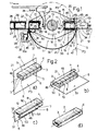
- Number 1 in Figure 1 indicates as a whole a packing unit for forming, as shown in Figure 2, a tubular wrapping 2 about a rectangular-prism-shaped product 3 having a longitudinal axis 4.
- product 3 is defined by a group of packets 5 of cigarettes arranged side by side along longitudinal axis 4 in two superimposed layers; and tubular wrapping 2 is coaxial with longitudinal axis 4 and formed by folding a sheet 6 of packing material about product 3 in a direction crosswise to longitudinal axis 4. More specifically, product 3 is defined laterally by two major lateral surfaces 7 and 8 parallel to each other and to longitudinal axis 4, and by two minor lateral surfaces 9 and 10 parallel to each other and to longitudinal axis 4, and perpendicular to major lateral surfaces 7 and 8.
- unit 1 comprises a packing wheel 11 fitted to a powered shaft 12, which has an axis 13, perpendicular to the Figure 1 plane, and is rotated in 180° steps about axis 13 in a direction 14 (clockwise in Figure 1).
- packing wheel 11 has two diametrically opposite radial pockets 15, each of which extends, parallel to axis 13, along packing wheel 11, is open both radially outwards and at the axial ends, and is defined by an end wall 16 parallel to axis 13 and having a longitudinal opening 17 parallel to axis 13, and by two facing lateral walls 18 and 19 parallel to axis 13 and perpendicular to end wall 16.
- Lateral wall 18 is located upstream from lateral wall 19 in direction 14; and lateral walls 18 and 19 of each pocket 15 define, together with relative end wall 16, a relative rectangular-prism-shaped seat 20 for receiving a relative product 3 positioned with its longitudinal axis 4 parallel to axis 13.
- Unit 1 also comprises a loading station 21 and an unloading station 22 located diametrically opposite each other outside packing wheel 11, which, at each rotation step of shaft 12 in direction 14, transfers one pocket 15 from loading station 21 to unloading station 22 along a packing path P1, and the other pocket 15 from unloading station 22 to loading station 21 along a return path P2.
- Loading station 21 comprises a pusher 23, which moves back and forth in a radial direction 24 with respect to axis 13, and cooperates with the minor lateral surface 10 of a product 3 - located at loading station 21 with longitudinal axis 4 parallel to axis 13 - to insert product 3 inside a pocket 15 - arrested at loading station 21 - so that product 3 is positioned, inside relative seat 20, with minor lateral surface 9 substantially contacting relative end wall 16, with major lateral surfaces 7 and 8 substantially contacting relative lateral walls 18 and 19, and with minor lateral surface 10 flush with an inlet 25 of relative seat 20 and with the outer periphery of packing wheel 11.
- Unloading station 22 comprises an unloading guide 26 located outside packing wheel 11 and comprising two facing plates 27 and 28 parallel to each other, to axis 13 and to direction 24, and of which plate 28 is located downstream from plate 27 in direction 14. More specifically, plates 27 and 28 are separated by a distance equal to the distance between walls 18 and 19 of each pocket 15, and approximately equal to but no less than the distance between major lateral surfaces 7 and 8 of product 3, and define, between them, an unloading passage 29 for unloading products 3.
- Unloading station 22 also comprises a pusher 31, which moves back and forth in direction 24 and cooperates, through opening 17 in a pocket 15 arrested at unloading station 22, with the minor lateral surface 10 of a product 3 housed inside said pocket 15, to expel product 3 from relative seat 20 to unloading guide 26 through unloading passage 29.
- Unit 1 also comprises a substantially semicylindrical fixed guide plate 32 coaxial with axis 13 and defined internally by a semicylindrical surface 33 extending along packing path P1 between loading station 21 and unloading station 22.
- Plate 32 is defined, at the end immediately downstream from loading station 21 in direction 14, by an end folding edge 34 parallel to axis 13, and, immediately upstream from unloading station 22, extends through a braking station 35 comprising an opening 36 formed through plate 32 and parallel to axis 13, and a hammer 37 of a gripper-type braking device 38.
- Hammer 37 comprises a lever 39 located outside plate 32 and hinged to a frame 39a to rotate, with respect to plate 32, about an axis 40 parallel to axis 13; a pad 41 made of resilient material, fitted integrally to a free end of lever 39, facing plate 32, and movable through opening 36 when lever 39 is rotated about axis 40; and a spring 42 for normally keeping pad 41 in a work position engaging opening 36 and interfering with packing path P1.
- braking device 38 comprises, for each pocket 15, an anvil 43 movable with relative pocket 15 along paths P1 and P2 and comprising a bracket 44 integral with an outer surface of relative lateral wall 18, and a roller 45, which extends along the whole length of relative pocket 15 in the direction of axis 13, is substantially the same length as pad 41, and is fitted to relative bracket 44 to rotate idly, with respect to relative pocket 15, about an axis 46 parallel to axis 13.
- Roller 45 has at least one peripheral portion made of resilient material, and is positioned with its outer surface tangent to the plane of inlet 25 of relative seat 20.
- a sheet 6 of packing material ( Figures 1 and 2a) is fed through loading station 21, along a plane P3 tangent to the outer periphery of packing wheel 11 and in a direction 47 crosswise to axis 13, and is arrested with a first intermediate portion 48 facing relative inlet 25 and interposed between inlet 25 and the minor lateral surface 9 of a product 3 ready for loading at loading station 21, and with an end portion 49, generally narrower than major lateral surfaces 7 and 8 of product 3, projecting upstream from relative inlet 25.
- Pusher 23 is then activated ( Figures 1 and 2b) to insert product 3 and relative sheet 6 of packing material inside relative seat 20 through relative inlet 25, and so fold sheet 6 of packing material into a U about relative product 3. More specifically, following insertion, sheet 6 of packing material is folded about relative product 3 with end portion 49 contacting part of major lateral surface 7 of relative product 3 and between major lateral surface 7 and lateral wall 18 of relative pocket 15; with intermediate portion 48 contacting minor lateral surface 9 of relative product 3 and between minor lateral surface 9 and end wall 16 of relative pocket 15; with a further intermediate portion 50 contacting major lateral surface 8 of relative product 3 and between major lateral surface 8 and lateral wall 19 of relative pocket 15; and with an end portion 51, opposite end portion 49, projecting radially outwards from relative seat 20 through relative inlet 25 and coplanar with the inner surface of lateral wall 19 of relative pocket 15.
- end portion 51 contacts end edge 34 of plate 32 and is folded backwards ( Figures 1 and 2c) so that a portion 52 of end portion 51 contacts minor lateral surface 10 of relative product 3, and an end portion 53 of end portion 51, opposite end portion 49 and generally slightly narrower than major lateral walls 7 and 8, projects rearwards of relative inlet 25, is substantially coplanar with minor lateral surface 10 of relative product 3, and contacts the outer surface of relative roller 45, the distance of which from the rear end of relative inlet 25 is less than the width of end portion 53.
- Sheet 6 of packing material remains in this position up to unloading station 22, where, upon operation of pusher 31, end portion 53 is brought into contact with and folded backwards by end edge 30 of plate 27, and, as relative product 3 is inserted inside unloading guide 26, is positioned contacting major lateral surface 7 of relative product 3 and overlapping end portion 49 to complete relative tubular wrapping 2.
- the pocket 15 considered is fed through braking station 35, where pad 41 frictionally engages portion 52 of sheet 6 of packing material, so as to exert braking action on the whole of end portion 51, which is thus maintained contacting minor lateral surface 10 of relative product 3 by tension acting in a direction 54 ( Figure 2c) opposite direction 14.
- braking device 38 provides for forming a tubular wrapping 2 adhering perfectly to the lateral surface of relative product 3.
- braking device 38 is totally passive, and requires no power or control device for its operation.
- braking device 38 may be replaced with any type of active braking device, such as a suction device (not shown), associated with plate 32.
Landscapes
- Engineering & Computer Science (AREA)
- Mechanical Engineering (AREA)
- Basic Packing Technique (AREA)
- Wrapping Of Specific Fragile Articles (AREA)
- Auxiliary Devices For And Details Of Packaging Control (AREA)
- Making Paper Articles (AREA)
- Shaping Of Tube Ends By Bending Or Straightening (AREA)
- Containers And Plastic Fillers For Packaging (AREA)
Abstract
Description
Claims (23)
- A method of forming a tubular wrapping about a rectangular-prism-shaped product, the method comprising a first folding step in which a sheet (6) of packing material is folded into a U about the product (3) so that an end portion (51) of the sheet of packing material projects crosswise to a longitudinal axis (4) of the product (3) and beyond the product (3) itself; and a second folding step in which said end portion (51) is folded further about the product (3) to define said tubular wrapping (2); and being characterized in that said end portion (51) is subjected, in the course of said second folding step, to traction in a direction (54) crosswise to said longitudinal axis (4); said first folding step being performed by placing said sheet (6) of packing material in front of, and so as to close, an inlet (25) of a U-shaped pocket (15) for said product (3); and inserting the product (3) and said sheet (6) of packing material inside said pocket (15) by moving said product (3) against said sheet (6) of packing material and through said inlet (25).
- A method as claimed in Claim 1, wherein, in the course of said first folding step, said sheet (6) of packing material is folded so as to be positioned with a first end portion (49) contacting at least part of a first lateral surface (7) of said product (3), and with two intermediate portions (48, 50) respectively contacting a second and a third lateral surface (9, 8) of said product (3); said second folding step comprising a first substep in which said end portion (51) is folded on to a fourth lateral surface (10) of said product (3), so that a second end portion (53) projects from said fourth lateral surface (10) and crosswise to said longitudinal axis (4), and a second substep in which said second end portion (53) is folded on to said first lateral surface (7) so as to at least overlap said first end portion (49); said traction being applied to said end portion (51) at least in the course of said second substep.
- A method as claimed in Claim 1 or 2, wherein said first lateral surface (7) is a major lateral surface (7) of said product (3) and said second lateral surface (9) is a minor lateral surface (9) of said product (3).
- A method as claimed in Claim 2 or 3, wherein said first substep is performed by feeding said pocket (15) in a feed direction (14) crosswise to said longitudinal axis (4) and along a packing path (P1) extending between a loading station (21), for loading said product (3) and said sheet (6) of packing material into said pocket (15), and an unloading station (22), and by interference between said end portion (51) and folding means (34) located along said packing path (P1); said traction being applied to said end portion (51) by braking means (38) located along said packing path (P1) and downstream from said folding means (34) in said feed direction (14).
- A method as claimed in Claim 4, wherein said second substep is performed by expelling said product (3) and said sheet (6) of packing material from said pocket (15) at said unloading station (22) in an unloading direction (24) crosswise to said third lateral surface (8), and by feeding the product (3) and the sheet (6) of packing material through a passage (29) of a width approximately equal to but no smaller than a width of said third lateral surface (8); said second end portion (53) being engaged by said braking means (38) during at least an initial portion of the travel of said product (3) and said sheet (6) of packing material through said passage (29).
- A method as claimed in any one of Claims 1 to 5, wherein said traction is applied by feeding said product (3) and said sheet (6) of packing material along a packing path (P1), and by said end portion (51) being engaged by braking means (38) located along said packing path (P1).
- A method as claimed in Claim 6, wherein said braking means (38) are passive braking means.
- A method as claimed in Claim 6 or 7, wherein said braking means (38) are mechanical friction braking means.
- A method as claimed in any one of Claims 6 to 8, wherein said braking means (38) are elastic gripper-type means.
- A method as claimed in any one of Claims 6 to 9, wherein said braking means (38) comprise an anvil (43) movable with said product (3) along said packing path (P1); and a hammer (37) located along said packing path (P1), at a braking station (35), and moved across said packing path (P1) by elastic means (42) to grip said end portion (51) against said anvil (43) as said product (3) reaches said unloading station (22).
- A method as claimed in Claim 10, wherein said anvil (43) comprises a roller (45) movable along said packing path (P1) with said product (3), and mounted to rotate idly, with respect to the product (3), about an axis (46) parallel to said longitudinal axis (4).
- A method as claimed in Claim 10, wherein at least one peripheral portion of said roller (45) is made of resilient material.
- A method as claimed in any one of Claims 10 to 12, wherein said hammer (37) comprises a pad (41) of resilient material.
- A unit for forming a tubular wrapping about a rectangular-prism-shaped product having a longitudinal axis (4), the unit comprising first folding means (20) for folding a sheet (6) of packing material into a U about said product (3) so that an end portion (51) of the sheet (6) of packing material projects crosswise to said longitudinal axis (4) and beyond said product (3); and second folding means (34, 30) for folding said end portion (51) about said product (3) to define said tubular wrapping (2); and being characterized by also comprising braking means (38) associated with said second folding means (34, 30) and for subjecting said end portion (51) to traction in a direction (54) crosswise to said longitudinal axis (4).
- A unit as claimed in Claim 14, comprising a packing wheel (11) mounted to rotate about an axis (13) of rotation; at least one pocket (15) located on said packing wheel (11) and for receiving a said product (3) positioned with the relative said longitudinal axis (4) parallel to said axis (13) of rotation, said pocket (15) being movable with said packing wheel (11) and in a given feed direction (14) between a loading station (21) and an unloading station (22) along a packing path (P1); an unloading guide (26) positioned with an inlet passage (29) at said unloading station (22); first push means (23) for transferring a said product (3) into said pocket (15) at said loading station (21); and second push means (31) for transferring said product (3) to said unloading guide (26) at said unloading station (22); said braking means (38) being located along said packing path (P1), upstream from said unloading station (22) in said feed direction (14).
- A unit as claimed in Claim 14 or 15, wherein said braking means (38) are passive braking means.
- A unit as claimed in any one of Claims 14 to 16, wherein said braking means (38) are mechanical friction braking means.
- A unit as claimed in any one of Claims 14 to 17, wherein said braking means (38) are elastic gripper-type means.
- A unit as claimed in any one of Claims 15 to 18, wherein said braking means (38) comprise an anvil (43) movable with said product (3) along said packing path (P1); and a hammer (37) located along said packing path (P1), at a braking station (35), and moved across said packing path (P1) by elastic means (42) to grip said end portion (51) against said anvil (43) as said product (3) reaches said unloading station (22).
- A unit as claimed in Claim 19, comprising a fixed plate (32) coaxial with said packing wheel (11) and extending, outside the packing wheel (11), between said loading and unloading stations (21, 22); an opening (36) being formed through said fixed plate (32) at said braking station (35) and at a given first distance from said unloading station (22) for the passage of said hammer (37).
- A unit as claimed in Claim 20, wherein said anvil (43) comprises a roller (45) fitted to said packing wheel (11) upstream from said pocket (15) and at a distance from the pocket (15) equal to said first distance; said roller (45) being fitted to said packing wheel (11) to rotate idly, with respect to said pocket (15), about an axis (46) parallel to the axis (13) of rotation of said packing wheel (11).
- A unit as claimed in Claim 21, wherein at least one peripheral portion of said roller (45) is made of resilient material.
- A unit as claimed in any one of Claims 19 to 22, wherein said hammer (37) comprises a pad (41) of resilient material.
Applications Claiming Priority (2)
| Application Number | Priority Date | Filing Date | Title |
|---|---|---|---|
| IT2001BO000346A ITBO20010346A1 (en) | 2001-05-30 | 2001-05-30 | METHOD AND UNIT FOR THE CREATION OF A TUBULAR WRAP AROUND A PRODUCT |
| ITBO20010346 | 2001-05-30 |
Publications (3)
| Publication Number | Publication Date |
|---|---|
| EP1262408A2 true EP1262408A2 (en) | 2002-12-04 |
| EP1262408A3 EP1262408A3 (en) | 2003-01-02 |
| EP1262408B1 EP1262408B1 (en) | 2004-05-12 |
Family
ID=11439391
Family Applications (1)
| Application Number | Title | Priority Date | Filing Date |
|---|---|---|---|
| EP02011923A Expired - Lifetime EP1262408B1 (en) | 2001-05-30 | 2002-05-29 | Method and unit for forming a tubular wrapping about a product |
Country Status (7)
| Country | Link |
|---|---|
| US (1) | US6675556B2 (en) |
| EP (1) | EP1262408B1 (en) |
| AT (1) | ATE266566T1 (en) |
| DE (1) | DE60200465T2 (en) |
| ES (1) | ES2218490T3 (en) |
| IT (1) | ITBO20010346A1 (en) |
| TR (1) | TR200401229T4 (en) |
Cited By (2)
| Publication number | Priority date | Publication date | Assignee | Title |
|---|---|---|---|---|
| DE102004046576A1 (en) * | 2004-09-23 | 2006-03-30 | Focke & Co.(Gmbh & Co. Kg) | Device for wrapping groups of packages |
| US8206529B2 (en) | 2006-03-03 | 2012-06-26 | Hoelterhoff Jens | Method and device for internal refurbishment of corroded hollow sections |
Families Citing this family (4)
| Publication number | Priority date | Publication date | Assignee | Title |
|---|---|---|---|---|
| ITBO20020210A1 (en) * | 2002-04-19 | 2003-10-20 | Gd Spa | WRAPPING METHOD OF CIGARETTE PACKAGES AND WRAPPING SHEET FOR THE REALIZATION OF THIS METHOD |
| US8989833B2 (en) | 2004-07-13 | 2015-03-24 | Dexcom, Inc. | Transcutaneous analyte sensor |
| ITBO20060237A1 (en) * | 2006-04-04 | 2006-07-04 | Gd Spa | METHOD AND MACHINE FOR THE PURCHASE OF ITEMS. |
| US8046978B2 (en) * | 2009-10-02 | 2011-11-01 | R.J. Reynolds Tobacco Company | Equipment and method for packaging multiple packets of cigarettes |
Citations (1)
| Publication number | Priority date | Publication date | Assignee | Title |
|---|---|---|---|---|
| US5305580A (en) | 1990-06-11 | 1994-04-26 | G.D Societa' Per Azioni | Method of producing tubular wrappings |
Family Cites Families (6)
| Publication number | Priority date | Publication date | Assignee | Title |
|---|---|---|---|---|
| US1485598A (en) * | 1921-02-08 | 1924-03-04 | Croxford Frederick Charles | Packing and wrapping up articles for transit and storage |
| US1946697A (en) * | 1931-03-19 | 1934-02-13 | Wrigley W M Jun Co | Package wrapping machine |
| IT1246012B (en) * | 1991-06-21 | 1994-11-07 | Gd Spa | WRAPPING METHOD AND DEVICE FOR THE PRODUCTION OF TUBULAR PRODUCT WRAPS. |
| IT1259800B (en) * | 1992-11-20 | 1996-03-26 | Gd Spa | METHOD AND DEVICE FOR THE CREATION OF TUBULAR SUPER-WRAPPING OF HEAT-SEALABLE MATERIAL. |
| IT1285921B1 (en) * | 1996-05-06 | 1998-06-26 | Gd Spa | METHOD FOR HANDLING PRODUCTS |
| IT1290696B1 (en) * | 1997-02-24 | 1998-12-10 | Gd Spa | METHOD AND MACHINE FOR THE WRAPPING OF PRODUCTS. |
-
2001
- 2001-05-30 IT IT2001BO000346A patent/ITBO20010346A1/en unknown
-
2002
- 2002-05-29 ES ES02011923T patent/ES2218490T3/en not_active Expired - Lifetime
- 2002-05-29 DE DE60200465T patent/DE60200465T2/en not_active Expired - Lifetime
- 2002-05-29 US US10/157,513 patent/US6675556B2/en not_active Expired - Fee Related
- 2002-05-29 AT AT02011923T patent/ATE266566T1/en not_active IP Right Cessation
- 2002-05-29 EP EP02011923A patent/EP1262408B1/en not_active Expired - Lifetime
- 2002-05-29 TR TR2004/01229T patent/TR200401229T4/en unknown
Patent Citations (1)
| Publication number | Priority date | Publication date | Assignee | Title |
|---|---|---|---|---|
| US5305580A (en) | 1990-06-11 | 1994-04-26 | G.D Societa' Per Azioni | Method of producing tubular wrappings |
Cited By (4)
| Publication number | Priority date | Publication date | Assignee | Title |
|---|---|---|---|---|
| DE102004046576A1 (en) * | 2004-09-23 | 2006-03-30 | Focke & Co.(Gmbh & Co. Kg) | Device for wrapping groups of packages |
| WO2006032428A1 (en) * | 2004-09-23 | 2006-03-30 | Focke & Co. (Gmbh & Co. Kg) | Device for covering packaging groups |
| US7555876B2 (en) | 2004-09-23 | 2009-07-07 | Focke & Co. (Gmbh & Co. Kg) | Device for covering packaging groups |
| US8206529B2 (en) | 2006-03-03 | 2012-06-26 | Hoelterhoff Jens | Method and device for internal refurbishment of corroded hollow sections |
Also Published As
| Publication number | Publication date |
|---|---|
| DE60200465D1 (en) | 2004-06-17 |
| ES2218490T3 (en) | 2004-11-16 |
| ITBO20010346A1 (en) | 2002-11-30 |
| EP1262408A3 (en) | 2003-01-02 |
| ITBO20010346A0 (en) | 2001-05-30 |
| US6675556B2 (en) | 2004-01-13 |
| DE60200465T2 (en) | 2005-05-12 |
| ATE266566T1 (en) | 2004-05-15 |
| TR200401229T4 (en) | 2004-08-23 |
| US20030009993A1 (en) | 2003-01-16 |
| EP1262408B1 (en) | 2004-05-12 |
Similar Documents
| Publication | Publication Date | Title |
|---|---|---|
| EP1854726B1 (en) | Cigarette packing machine | |
| EP2419337B1 (en) | Device for packaging a product in an envelope | |
| EP1227040B1 (en) | Method and machine for packing reams of sheets | |
| US5996318A (en) | Packet wrapping method and unit | |
| EP0865987B1 (en) | Folding method for forming a sealed tubular wrapping | |
| JPH06528B2 (en) | Method and apparatus for packaging a pack of cigarettes into a film blank | |
| EP0940339B1 (en) | Continuous product wrapping method and machine | |
| EP0890512B1 (en) | Method and unit for feeding collars for rigid packets of cigarettes to a continuous packing line | |
| EP0519402B1 (en) | Product wrapping method and device for producing tubular wrappings | |
| EP1452448A1 (en) | Method of producing soft packets of cigarettes | |
| EP0529404A1 (en) | Device for packing packets, particularly of cigarettes, in groups | |
| EP0860358A1 (en) | Product wrapping method and machine | |
| EP0806350B1 (en) | Product manipulating method | |
| EP1262408B1 (en) | Method and unit for forming a tubular wrapping about a product | |
| US6904738B2 (en) | Method and unit for packing groups of products | |
| EP0970886A1 (en) | Method and machine for wrapping a product | |
| EP1842774B1 (en) | Method and machine for packing articles | |
| EP0792807B1 (en) | Method and unit for folding packing blanks along preformed bend lines | |
| EP1346916A1 (en) | A method and a unit for feeding elements of sheet material to a product wrapping line | |
| US20070240388A1 (en) | Cigarette packing machine and method | |
| EP0972704A1 (en) | Method and machine for wrapping products | |
| WO2006131527A1 (en) | Method and machine for producing a sealed wrapping about a product, and wrapping obtained using such a method | |
| EP1150886B1 (en) | Method and machine for wrapping articles | |
| JPH101103A (en) | Product-wrapping method | |
| JP2005154009A (en) | Unit for packaging product |
Legal Events
| Date | Code | Title | Description |
|---|---|---|---|
| PUAI | Public reference made under article 153(3) epc to a published international application that has entered the european phase |
Free format text: ORIGINAL CODE: 0009012 |
|
| PUAL | Search report despatched |
Free format text: ORIGINAL CODE: 0009013 |
|
| AK | Designated contracting states |
Kind code of ref document: A2 Designated state(s): AT BE CH CY DE DK ES FI FR GB GR IE IT LI LU MC NL PT SE TR |
|
| AX | Request for extension of the european patent |
Free format text: AL;LT;LV;MK;RO;SI |
|
| AK | Designated contracting states |
Kind code of ref document: A3 Designated state(s): AT BE CH CY DE DK ES FI FR GB GR IE IT LI LU MC NL PT SE TR |
|
| AX | Request for extension of the european patent |
Free format text: AL;LT;LV;MK;RO;SI |
|
| RAP1 | Party data changed (applicant data changed or rights of an application transferred) |
Owner name: G.D SOCIETA' PER AZIONI |
|
| 17P | Request for examination filed |
Effective date: 20030630 |
|
| AKX | Designation fees paid |
Designated state(s): AT BE CH CY DE DK ES FI FR GB GR IE IT LI LU MC NL PT SE TR |
|
| GRAP | Despatch of communication of intention to grant a patent |
Free format text: ORIGINAL CODE: EPIDOSNIGR1 |
|
| GRAS | Grant fee paid |
Free format text: ORIGINAL CODE: EPIDOSNIGR3 |
|
| GRAA | (expected) grant |
Free format text: ORIGINAL CODE: 0009210 |
|
| AK | Designated contracting states |
Kind code of ref document: B1 Designated state(s): AT BE CH CY DE DK ES FI FR GB GR IE IT LI LU MC NL PT SE TR |
|
| PG25 | Lapsed in a contracting state [announced via postgrant information from national office to epo] |
Ref country code: AT Free format text: LAPSE BECAUSE OF FAILURE TO SUBMIT A TRANSLATION OF THE DESCRIPTION OR TO PAY THE FEE WITHIN THE PRESCRIBED TIME-LIMIT Effective date: 20040512 Ref country code: BE Free format text: LAPSE BECAUSE OF FAILURE TO SUBMIT A TRANSLATION OF THE DESCRIPTION OR TO PAY THE FEE WITHIN THE PRESCRIBED TIME-LIMIT Effective date: 20040512 Ref country code: CY Free format text: LAPSE BECAUSE OF FAILURE TO SUBMIT A TRANSLATION OF THE DESCRIPTION OR TO PAY THE FEE WITHIN THE PRESCRIBED TIME-LIMIT Effective date: 20040512 Ref country code: FI Free format text: LAPSE BECAUSE OF FAILURE TO SUBMIT A TRANSLATION OF THE DESCRIPTION OR TO PAY THE FEE WITHIN THE PRESCRIBED TIME-LIMIT Effective date: 20040512 Ref country code: NL Free format text: LAPSE BECAUSE OF FAILURE TO SUBMIT A TRANSLATION OF THE DESCRIPTION OR TO PAY THE FEE WITHIN THE PRESCRIBED TIME-LIMIT Effective date: 20040512 |
|
| REG | Reference to a national code |
Ref country code: GB Ref legal event code: FG4D |
|
| REG | Reference to a national code |
Ref country code: CH Ref legal event code: EP |
|
| PGFP | Annual fee paid to national office [announced via postgrant information from national office to epo] |
Ref country code: FR Payment date: 20040519 Year of fee payment: 3 |
|
| PG25 | Lapsed in a contracting state [announced via postgrant information from national office to epo] |
Ref country code: LU Free format text: LAPSE BECAUSE OF NON-PAYMENT OF DUE FEES Effective date: 20040529 |
|
| PG25 | Lapsed in a contracting state [announced via postgrant information from national office to epo] |
Ref country code: IE Free format text: LAPSE BECAUSE OF NON-PAYMENT OF DUE FEES Effective date: 20040531 Ref country code: MC Free format text: LAPSE BECAUSE OF NON-PAYMENT OF DUE FEES Effective date: 20040531 |
|
| REG | Reference to a national code |
Ref country code: CH Ref legal event code: NV Representative=s name: CABINET ROLAND NITHARDT CONSEILS EN PROPRIETE INDU |
|
| REG | Reference to a national code |
Ref country code: IE Ref legal event code: FG4D |
|
| REF | Corresponds to: |
Ref document number: 60200465 Country of ref document: DE Date of ref document: 20040617 Kind code of ref document: P |
|
| PG25 | Lapsed in a contracting state [announced via postgrant information from national office to epo] |
Ref country code: GR Free format text: LAPSE BECAUSE OF FAILURE TO SUBMIT A TRANSLATION OF THE DESCRIPTION OR TO PAY THE FEE WITHIN THE PRESCRIBED TIME-LIMIT Effective date: 20040812 Ref country code: DK Free format text: LAPSE BECAUSE OF FAILURE TO SUBMIT A TRANSLATION OF THE DESCRIPTION OR TO PAY THE FEE WITHIN THE PRESCRIBED TIME-LIMIT Effective date: 20040812 Ref country code: SE Free format text: LAPSE BECAUSE OF FAILURE TO SUBMIT A TRANSLATION OF THE DESCRIPTION OR TO PAY THE FEE WITHIN THE PRESCRIBED TIME-LIMIT Effective date: 20040812 |
|
| NLV1 | Nl: lapsed or annulled due to failure to fulfill the requirements of art. 29p and 29m of the patents act | ||
| REG | Reference to a national code |
Ref country code: ES Ref legal event code: FG2A Ref document number: 2218490 Country of ref document: ES Kind code of ref document: T3 |
|
| ET | Fr: translation filed | ||
| REG | Reference to a national code |
Ref country code: IE Ref legal event code: MM4A |
|
| PLBE | No opposition filed within time limit |
Free format text: ORIGINAL CODE: 0009261 |
|
| STAA | Information on the status of an ep patent application or granted ep patent |
Free format text: STATUS: NO OPPOSITION FILED WITHIN TIME LIMIT |
|
| 26N | No opposition filed |
Effective date: 20050215 |
|
| PG25 | Lapsed in a contracting state [announced via postgrant information from national office to epo] |
Ref country code: FR Free format text: LAPSE BECAUSE OF NON-PAYMENT OF DUE FEES Effective date: 20060131 |
|
| REG | Reference to a national code |
Ref country code: FR Ref legal event code: ST Effective date: 20060131 |
|
| PGFP | Annual fee paid to national office [announced via postgrant information from national office to epo] |
Ref country code: ES Payment date: 20070528 Year of fee payment: 6 |
|
| PGFP | Annual fee paid to national office [announced via postgrant information from national office to epo] |
Ref country code: GB Payment date: 20070525 Year of fee payment: 6 |
|
| PG25 | Lapsed in a contracting state [announced via postgrant information from national office to epo] |
Ref country code: PT Free format text: LAPSE BECAUSE OF NON-PAYMENT OF DUE FEES Effective date: 20041012 |
|
| PGFP | Annual fee paid to national office [announced via postgrant information from national office to epo] |
Ref country code: IT Payment date: 20070524 Year of fee payment: 6 |
|
| GBPC | Gb: european patent ceased through non-payment of renewal fee |
Effective date: 20080529 |
|
| PG25 | Lapsed in a contracting state [announced via postgrant information from national office to epo] |
Ref country code: GB Free format text: LAPSE BECAUSE OF NON-PAYMENT OF DUE FEES Effective date: 20080529 |
|
| REG | Reference to a national code |
Ref country code: ES Ref legal event code: FD2A Effective date: 20080530 |
|
| PG25 | Lapsed in a contracting state [announced via postgrant information from national office to epo] |
Ref country code: IT Free format text: LAPSE BECAUSE OF NON-PAYMENT OF DUE FEES Effective date: 20080529 |
|
| PGFP | Annual fee paid to national office [announced via postgrant information from national office to epo] |
Ref country code: TR Payment date: 20090508 Year of fee payment: 8 |
|
| PG25 | Lapsed in a contracting state [announced via postgrant information from national office to epo] |
Ref country code: ES Free format text: LAPSE BECAUSE OF NON-PAYMENT OF DUE FEES Effective date: 20080530 |
|
| PGFP | Annual fee paid to national office [announced via postgrant information from national office to epo] |
Ref country code: CH Payment date: 20090526 Year of fee payment: 8 |
|
| REG | Reference to a national code |
Ref country code: CH Ref legal event code: PL |
|
| PG25 | Lapsed in a contracting state [announced via postgrant information from national office to epo] |
Ref country code: LI Free format text: LAPSE BECAUSE OF NON-PAYMENT OF DUE FEES Effective date: 20100531 Ref country code: CH Free format text: LAPSE BECAUSE OF NON-PAYMENT OF DUE FEES Effective date: 20100531 |
|
| PG25 | Lapsed in a contracting state [announced via postgrant information from national office to epo] |
Ref country code: TR Free format text: LAPSE BECAUSE OF NON-PAYMENT OF DUE FEES Effective date: 20100529 |
|
| PGFP | Annual fee paid to national office [announced via postgrant information from national office to epo] |
Ref country code: DE Payment date: 20130530 Year of fee payment: 12 |
|
| REG | Reference to a national code |
Ref country code: DE Ref legal event code: R119 Ref document number: 60200465 Country of ref document: DE |
|
| REG | Reference to a national code |
Ref country code: DE Ref legal event code: R119 Ref document number: 60200465 Country of ref document: DE Effective date: 20141202 |
|
| PG25 | Lapsed in a contracting state [announced via postgrant information from national office to epo] |
Ref country code: DE Free format text: LAPSE BECAUSE OF NON-PAYMENT OF DUE FEES Effective date: 20141202 |