EP1261113A2 - High temperature superconducting rotor power leads - Google Patents
High temperature superconducting rotor power leads Download PDFInfo
- Publication number
- EP1261113A2 EP1261113A2 EP02253333A EP02253333A EP1261113A2 EP 1261113 A2 EP1261113 A2 EP 1261113A2 EP 02253333 A EP02253333 A EP 02253333A EP 02253333 A EP02253333 A EP 02253333A EP 1261113 A2 EP1261113 A2 EP 1261113A2
- Authority
- EP
- European Patent Office
- Prior art keywords
- rotor
- heat station
- return flow
- hts
- coupled
- Prior art date
- Legal status (The legal status is an assumption and is not a legal conclusion. Google has not performed a legal analysis and makes no representation as to the accuracy of the status listed.)
- Granted
Links
- 239000000919 ceramic Substances 0.000 claims abstract description 26
- 239000012212 insulator Substances 0.000 claims abstract description 25
- 238000004804 winding Methods 0.000 claims description 33
- LTPBRCUWZOMYOC-UHFFFAOYSA-N Beryllium oxide Chemical compound O=[Be] LTPBRCUWZOMYOC-UHFFFAOYSA-N 0.000 claims description 13
- RYGMFSIKBFXOCR-UHFFFAOYSA-N Copper Chemical compound [Cu] RYGMFSIKBFXOCR-UHFFFAOYSA-N 0.000 claims description 12
- 229910052802 copper Inorganic materials 0.000 claims description 12
- 239000010949 copper Substances 0.000 claims description 12
- 238000010438 heat treatment Methods 0.000 claims description 7
- 229910052594 sapphire Inorganic materials 0.000 claims description 6
- 239000010980 sapphire Substances 0.000 claims description 6
- 238000001816 cooling Methods 0.000 claims description 5
- 239000002826 coolant Substances 0.000 claims description 3
- 230000008602 contraction Effects 0.000 abstract 1
- 229910052751 metal Inorganic materials 0.000 description 4
- 239000002184 metal Substances 0.000 description 4
- 230000001360 synchronised effect Effects 0.000 description 4
- 238000010292 electrical insulation Methods 0.000 description 2
- FRWYFWZENXDZMU-UHFFFAOYSA-N 2-iodoquinoline Chemical compound C1=CC=CC2=NC(I)=CC=C21 FRWYFWZENXDZMU-UHFFFAOYSA-N 0.000 description 1
- 230000001133 acceleration Effects 0.000 description 1
- 230000015556 catabolic process Effects 0.000 description 1
- 238000010276 construction Methods 0.000 description 1
- 239000012809 cooling fluid Substances 0.000 description 1
- 230000008878 coupling Effects 0.000 description 1
- 238000010168 coupling process Methods 0.000 description 1
- 238000005859 coupling reaction Methods 0.000 description 1
- 230000000593 degrading effect Effects 0.000 description 1
- 239000011152 fibreglass Substances 0.000 description 1
- 239000012530 fluid Substances 0.000 description 1
- 230000005405 multipole Effects 0.000 description 1
- 239000011343 solid material Substances 0.000 description 1
Images


Classifications
-
- H—ELECTRICITY
- H02—GENERATION; CONVERSION OR DISTRIBUTION OF ELECTRIC POWER
- H02K—DYNAMO-ELECTRIC MACHINES
- H02K55/00—Dynamo-electric machines having windings operating at cryogenic temperatures
- H02K55/02—Dynamo-electric machines having windings operating at cryogenic temperatures of the synchronous type
- H02K55/04—Dynamo-electric machines having windings operating at cryogenic temperatures of the synchronous type with rotating field windings
-
- H—ELECTRICITY
- H02—GENERATION; CONVERSION OR DISTRIBUTION OF ELECTRIC POWER
- H02K—DYNAMO-ELECTRIC MACHINES
- H02K3/00—Details of windings
- H02K3/02—Windings characterised by the conductor material
-
- H—ELECTRICITY
- H01—ELECTRIC ELEMENTS
- H01F—MAGNETS; INDUCTANCES; TRANSFORMERS; SELECTION OF MATERIALS FOR THEIR MAGNETIC PROPERTIES
- H01F6/00—Superconducting magnets; Superconducting coils
- H01F6/06—Coils, e.g. winding, insulating, terminating or casing arrangements therefor
- H01F6/065—Feed-through bushings, terminals and joints
-
- Y—GENERAL TAGGING OF NEW TECHNOLOGICAL DEVELOPMENTS; GENERAL TAGGING OF CROSS-SECTIONAL TECHNOLOGIES SPANNING OVER SEVERAL SECTIONS OF THE IPC; TECHNICAL SUBJECTS COVERED BY FORMER USPC CROSS-REFERENCE ART COLLECTIONS [XRACs] AND DIGESTS
- Y02—TECHNOLOGIES OR APPLICATIONS FOR MITIGATION OR ADAPTATION AGAINST CLIMATE CHANGE
- Y02E—REDUCTION OF GREENHOUSE GAS [GHG] EMISSIONS, RELATED TO ENERGY GENERATION, TRANSMISSION OR DISTRIBUTION
- Y02E40/00—Technologies for an efficient electrical power generation, transmission or distribution
- Y02E40/60—Superconducting electric elements or equipment; Power systems integrating superconducting elements or equipment
Definitions
- the present invention relates generally to synchronous rotating machines. More particularly, the present invention relates to power leads for high temperature superconducting field windings in the rotor of a synchronous machine.
- Synchronous electrical machines having field coil windings include, but are not limited to, rotary generators, rotary motors, and linear motors. These machines generally comprise a stator and rotor that are electro-magnetically coupled.
- the rotor may include a multi-pole rotor core and coil windings mounted on the rotor core.
- the rotor cores may include a magnetically-permeable solid material, such as an iron-core rotor.
- Typical superconducting rotor windings are made from saddle shaped coils that are assembled around cylindrical shells for structural support. These saddle shaped coils are complex winding structures that are cooled in direct contact with cryogens. The power leads are also cooled by cryogens through parallel flow circuit paths that present a challenge to control flow rate and temperature stability in the high centrifugal acceleration fields.
- a power lead for a high temperature superconducting (HTS) rotor winding coil.
- the power lead includes a heat station block attachable to a return flow tubing bulkhead, a ceramic insulator securable between the heat station block and the return flow tubing bulkhead, and thermally optimized current leads coupled with the heat station block.
- the heat station block includes two half-blocks that are sized to sandwich the return flow tubing bulkhead, wherein the power lead includes two thermally optimized current leads, one each coupled with each of the heat station half-blocks.
- the half-blocks may be secured to each other with electrically insulated bolts.
- the ceramic insulator may be formed of one of beryllia and sapphire and may be metal plated on both sides excluding edges thereof.
- the thermally optimized current leads are particularly configured with a cross-section, length and electrical resistance to carry rotor current with margin for transients while minimizing heat transfer as a result of ohmic resistance heating and thermal conduction heat transfer.
- a power lead for an HTS rotor winding coil includes heat station blocks electrically couplable with a rotor of an electrical machine.
- the heat station blocks are electrically insulated from a return flow tubing while being thermally coupled with the return flow tubing via a ceramic insulator interposed therebetween for thermal conductivity between the heat station blocks and the return flow tubing.
- an electric machine in yet another exemplary embodiment of the invention, includes a stator and a rotor coupled with the stator for rotation relative to the stator about a rotor axis.
- the rotor includes lead terminals disposed in a vicinity of the rotor axis.
- a return flow tubing is provided for carrying a coolant for heat exchanger cooling, and an HTS rotor winding coil is coupled with the rotor lead terminals via the HTS power leads of the present invention.
- Lead sections of braided copper or the like are preferably coupled between the heat station block and the rotor lead terminals.
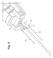
- the HTS coil start and finish leads are preferably soldered to copper terminals 14 that are located near the rotor axis so that they are subjected to low centrifugal loads.
- Return flow tubing 20 carries cryogens from the HTS coil heat-exchanger cooling tube, adjacent the copper terminals 14, to the end of the rotor shaft (shown in Fig. 8) where a fluid transfer coupling delivers the cryogens to an external source of cryogenic cooling fluid.
- Short braided copper lead sections 12 connect the coil terminals 14 to copper heat station blocks 16.
- the heat station blocks 16 are formed of two half-blocks that are sized to sandwich the bulkhead 18 of the return flow tubing 20.
- the heat station half-blocks 16 are bolted to each other with electrically insulated bolts 24 as shown in FIGURE 9, which support the centrifugal loading.
- Metal-plated ceramic insulators 22 are soldered on one side to the heat station blocks 16 and on the other side to the return flow tubing bulkhead 18 so that the power leads are conduction cooled to reject heat to the rotor return flow path.
- the heat station blocks 16 are electrically insulated from the return flow tubing 20 by the ceramic insulators 22 but reject heat efficiently with low temperature difference because the ceramic insulators 22 are designed for high thermal conductivity at cryogenic temperatures.
- the ceramic insulators 22 are typically made of thin plates of beryllia (beryllium oxide) or sapphire that are metal-plated on both sides excluding the edges thereof in order to provide adequate electrical insulation to the HTS coil. Typical insulator thicknesses vary from 0.040" to 0.125". Thicker insulators improve the electrical insulation or voltage breakdown capability of the HTS coil at the expense of degrading the cooling capacity of the heat station.
- Thermally optimized current leads 26 are soldered on one end to the heat station blocks 16 and on the other end to braided copper lead sections 28 that connect to the ceramic vacuum feed throughs (vacuum tight ceramic insulated copper terminals).
- the current leads 26 are optimized to carry the highest current for the lowest thermal load to the heat station.
- the cross-section, length and electrical resistance of the thermally optimized lead sections 26 are designed to carry the rotor current with ample margin for transients and minimize the heat transfer to the cold end as a result of ohmic resistance heating and thermal conduction heat transfer.
- the thermally optimized sections of the power leads are supported by a thin wall thermal stand-off fiberglass tube 30 that is attached to the rotor bore at one end and supports the heat station blocks 16 and return tubing bulkhead 18 at the other end.
- heat station blocks of the power lead are electrically coupleable with a rotor of an electrical machine and are electrically insulated from a return flow tubing while being thermally coupled with the return flow tubing via a ceramic insulator interposed therebetween.
- the ceramic insulator provides for thermal conductivity between the heat station blocks and the return flow tubing.
Landscapes
- Engineering & Computer Science (AREA)
- Power Engineering (AREA)
- Superconductive Dynamoelectric Machines (AREA)
- Insulation, Fastening Of Motor, Generator Windings (AREA)
- Superconductors And Manufacturing Methods Therefor (AREA)
- Superconductor Devices And Manufacturing Methods Thereof (AREA)
- Inorganic Compounds Of Heavy Metals (AREA)
- Gas Or Oil Filled Cable Accessories (AREA)
Abstract
Description
Claims (10)
- A power lead for a high temperature superconducting (HTS) rotor winding coil, the power lead comprising:a heat station block (16) attachable to a return flow tubing bulkhead (18);a ceramic insulator (22) securable between the heat station block and the return flow tubing bulkhead; andthermally optimized current leads (26) coupled with the heat station block.
- A power lead for an HTS rotor winding coil according to claim 1, wherein the heat station block (16) comprises two half-blocks that are sized to sandwich the return flow tubing bulkhead (18), and wherein the power lead comprises two thermally optimized current leads (26), one each coupled with each of the heat station half-blocks.
- A power lead for an HTS rotor winding coil according to claim 2, wherein the half-blocks are secured to each other with electrically insulated bolts (24).
- A power lead for an HTS rotor winding coil according to claim 1, 2 or 3, wherein the ceramic insulator (22) is formed of one of beryllia and sapphire.
- A power lead for a high temperature superconducting (HTS) rotor winding coil, the power lead comprising heat station blocks (16) electrically coupleable with a rotor of an electrical machine, the heat station blocks being electrically insulated from a return flow tubing (20) while being thermally coupled with the return flow tubing via a ceramic insulator (22) interposed therebetween for thermal conductivity between the heat station blocks and the return flow tubing.
- A power lead for an HTS rotor winding coil according to claim 5, further comprising thermally optimized current leads (26) coupled with the heat station blocks (16).
- A power lead for an HTS rotor winding coil according to claim 6, wherein the thermally optimized current leads (26) are particularly configured with a cross-section, length and electrical resistance to carry rotor current with margin for transients while minimizing heat transfer as a result of ohmic resistance heating and thermal conduction heat transfer.
- An electric machine comprising:a stator;a rotor coupled with the stator for rotation relative to the stator about a rotor axis, the rotor including lead terminals disposed in a vicinity of the rotor axis;a return flow tubing carrying a coolant for heat exchanger cooling; anda high temperature superconducting (HTS) rotor winding coil coupled with the rotor lead terminals via resistive power leads, the power leads comprising:a heat station block (16) attachable to a bulkhead (18) of the return flow tubing,a ceramic insulator (22) securable between the heat station block and the return flow tubing bulkhead, andthermally optimized current leads (26) coupled with the heat station block.
- An electric machine according to claim 8, further comprising lead sections (12) coupled between the heat station block and the rotor lead terminals.
- An electric machine according to claim 9, wherein the lead sections (12) comprise braided copper.
Applications Claiming Priority (2)
| Application Number | Priority Date | Filing Date | Title |
|---|---|---|---|
| US09/855,034 US6577028B2 (en) | 2001-05-15 | 2001-05-15 | High temperature superconducting rotor power leads |
| US855034 | 2001-05-15 |
Publications (3)
| Publication Number | Publication Date |
|---|---|
| EP1261113A2 true EP1261113A2 (en) | 2002-11-27 |
| EP1261113A3 EP1261113A3 (en) | 2002-12-11 |
| EP1261113B1 EP1261113B1 (en) | 2006-04-05 |
Family
ID=25320166
Family Applications (1)
| Application Number | Title | Priority Date | Filing Date |
|---|---|---|---|
| EP02253333A Expired - Lifetime EP1261113B1 (en) | 2001-05-15 | 2002-05-14 | High temperature superconducting rotor power leads |
Country Status (13)
| Country | Link |
|---|---|
| US (1) | US6577028B2 (en) |
| EP (1) | EP1261113B1 (en) |
| JP (1) | JP4035371B2 (en) |
| KR (1) | KR100902428B1 (en) |
| CN (1) | CN1311616C (en) |
| AT (1) | ATE322756T1 (en) |
| BR (1) | BR0201805B1 (en) |
| CA (1) | CA2384481C (en) |
| CZ (1) | CZ301682B6 (en) |
| DE (1) | DE60210366T2 (en) |
| MX (1) | MXPA02004830A (en) |
| NO (1) | NO325511B1 (en) |
| PL (1) | PL200952B1 (en) |
Cited By (1)
| Publication number | Priority date | Publication date | Assignee | Title |
|---|---|---|---|---|
| FR2872642A1 (en) * | 2004-06-30 | 2006-01-06 | Valeo Equip Electr Moteur | POWER SUPPLY CIRCUIT FOR AN ELECTRIC MOTOR BRUSH, IN PARTICULAR A MOTOR VEHICLE STARTER |
Families Citing this family (7)
| Publication number | Priority date | Publication date | Assignee | Title |
|---|---|---|---|---|
| US7312544B2 (en) * | 2005-02-15 | 2007-12-25 | General Electric Company | Fluid transfer device and method for conveying fluid to a rotating member |
| CN102592773B (en) * | 2012-03-05 | 2013-06-26 | 宁波健信机械有限公司 | Separable HTS current leads for MRI superconducting magnets |
| US20130241330A1 (en) * | 2012-03-19 | 2013-09-19 | Hamilton Sundstrand Corporation | Aircraft dynamoelectric machine with feeder lug heatsink |
| CN103633816B (en) * | 2012-12-12 | 2016-02-03 | 西南交通大学 | A kind of super conduction synchronous electric motor |
| US9552906B1 (en) | 2015-09-01 | 2017-01-24 | General Electric Company | Current lead for cryogenic apparatus |
| DE102018215917A1 (en) * | 2018-08-21 | 2020-02-27 | Siemens Aktiengesellschaft | Rotor with rotor winding for operation in continuous current mode |
| JP7840890B2 (en) * | 2023-02-24 | 2026-04-06 | 株式会社東芝 | Rotor of a superconducting rotating electric machine and superconducting rotating electric machine |
Family Cites Families (24)
| Publication number | Priority date | Publication date | Assignee | Title |
|---|---|---|---|---|
| FR2274158A1 (en) * | 1974-06-07 | 1976-01-02 | Anvar | IMPROVEMENTS IN ELECTRIC ROTATING MACHINES WITH SUPPRACONDUCTOR WINDING |
| US4164671A (en) * | 1978-05-22 | 1979-08-14 | General Electric Company | Resistor-containing cryogenic current lead |
| JPS5681077A (en) * | 1979-12-04 | 1981-07-02 | Hitachi Ltd | Superconductive rotor |
| JPS5716571A (en) * | 1980-07-01 | 1982-01-28 | Hitachi Ltd | Superconductive rotor |
| US4543794A (en) * | 1983-07-26 | 1985-10-01 | Kabushiki Kaisha Toshiba | Superconducting magnet device |
| US4876413A (en) * | 1988-07-05 | 1989-10-24 | General Electric Company | Efficient thermal joints for connecting current leads to a cryocooler |
| JPH02294248A (en) * | 1989-04-04 | 1990-12-05 | Vses N I Proekt Konstr Tech Inst Vzryv | Electric machine with rotor cooling centrifugal heat exchanger tube |
| JPH0774018A (en) * | 1993-09-06 | 1995-03-17 | Fuji Electric Co Ltd | Superconducting device current lead |
| US5385022A (en) * | 1993-09-09 | 1995-01-31 | Kornblit; Levy | Apparatus and method for deep thermoelectric refrigeration |
| US5531015A (en) | 1994-01-28 | 1996-07-02 | American Superconductor Corporation | Method of making superconducting wind-and-react coils |
| JP2952552B2 (en) * | 1994-04-20 | 1999-09-27 | 住友重機械工業株式会社 | Current leads for superconducting equipment |
| JPH07335422A (en) * | 1994-06-10 | 1995-12-22 | Hitachi Ltd | Current lead for superconducting device |
| US5548168A (en) | 1994-06-29 | 1996-08-20 | General Electric Company | Superconducting rotor for an electrical machine |
| US5625548A (en) | 1994-08-10 | 1997-04-29 | American Superconductor Corporation | Control circuit for cryogenically-cooled power electronics employed in power conversion systems |
| US5802855A (en) | 1994-11-21 | 1998-09-08 | Yamaguchi; Sataro | Power lead for electrically connecting a superconducting coil to a power supply |
| US5532663A (en) | 1995-03-13 | 1996-07-02 | General Electric Company | Support structure for a superconducting coil |
| US5672921A (en) | 1995-03-13 | 1997-09-30 | General Electric Company | Superconducting field winding assemblage for an electrical machine |
| US5777420A (en) | 1996-07-16 | 1998-07-07 | American Superconductor Corporation | Superconducting synchronous motor construction |
| US6173577B1 (en) | 1996-08-16 | 2001-01-16 | American Superconductor Corporation | Methods and apparatus for cooling systems for cryogenic power conversion electronics |
| US5774032A (en) | 1996-08-23 | 1998-06-30 | General Electric Company | Cooling arrangement for a superconducting coil |
| US6140719A (en) | 1999-02-17 | 2000-10-31 | American Superconductor Corporation | High temperature superconducting rotor for a synchronous machine |
| US6066906A (en) | 1999-02-17 | 2000-05-23 | American Superconductor Corporation | Rotating machine having superconducting windings |
| KR100310631B1 (en) * | 1999-03-12 | 2001-10-17 | 윤문수 | Superconducting Rotor for Generator and Motor |
| US6169353B1 (en) | 1999-09-28 | 2001-01-02 | Reliance Electric Technologies, Llc | Method for manufacturing a rotor having superconducting coils |
-
2001
- 2001-05-15 US US09/855,034 patent/US6577028B2/en not_active Expired - Lifetime
-
2002
- 2002-05-02 CA CA2384481A patent/CA2384481C/en not_active Expired - Fee Related
- 2002-05-14 JP JP2002138010A patent/JP4035371B2/en not_active Expired - Fee Related
- 2002-05-14 DE DE60210366T patent/DE60210366T2/en not_active Expired - Lifetime
- 2002-05-14 NO NO20022307A patent/NO325511B1/en not_active IP Right Cessation
- 2002-05-14 MX MXPA02004830A patent/MXPA02004830A/en active IP Right Grant
- 2002-05-14 AT AT02253333T patent/ATE322756T1/en not_active IP Right Cessation
- 2002-05-14 EP EP02253333A patent/EP1261113B1/en not_active Expired - Lifetime
- 2002-05-14 CZ CZ20021678A patent/CZ301682B6/en not_active IP Right Cessation
- 2002-05-14 KR KR1020020026321A patent/KR100902428B1/en not_active Expired - Fee Related
- 2002-05-15 PL PL353908A patent/PL200952B1/en unknown
- 2002-05-15 CN CNB02123339XA patent/CN1311616C/en not_active Expired - Fee Related
- 2002-05-15 BR BRPI0201805-5A patent/BR0201805B1/en not_active IP Right Cessation
Cited By (2)
| Publication number | Priority date | Publication date | Assignee | Title |
|---|---|---|---|---|
| FR2872642A1 (en) * | 2004-06-30 | 2006-01-06 | Valeo Equip Electr Moteur | POWER SUPPLY CIRCUIT FOR AN ELECTRIC MOTOR BRUSH, IN PARTICULAR A MOTOR VEHICLE STARTER |
| WO2006010862A1 (en) * | 2004-06-30 | 2006-02-02 | Valeo Equipements Electriques Moteur | Powering circuit for an electric motor brush, in particular of a motor vehicle starter |
Also Published As
| Publication number | Publication date |
|---|---|
| CA2384481A1 (en) | 2002-11-15 |
| EP1261113A3 (en) | 2002-12-11 |
| CZ20021678A3 (en) | 2003-01-15 |
| DE60210366D1 (en) | 2006-05-18 |
| CN1385946A (en) | 2002-12-18 |
| DE60210366T2 (en) | 2007-01-11 |
| PL200952B1 (en) | 2009-02-27 |
| BR0201805B1 (en) | 2011-12-13 |
| JP4035371B2 (en) | 2008-01-23 |
| JP2003037957A (en) | 2003-02-07 |
| CZ301682B6 (en) | 2010-05-26 |
| US6577028B2 (en) | 2003-06-10 |
| ATE322756T1 (en) | 2006-04-15 |
| KR100902428B1 (en) | 2009-06-11 |
| NO20022307L (en) | 2002-11-18 |
| BR0201805A (en) | 2004-03-23 |
| CN1311616C (en) | 2007-04-18 |
| MXPA02004830A (en) | 2004-12-13 |
| CA2384481C (en) | 2011-03-15 |
| EP1261113B1 (en) | 2006-04-05 |
| KR20020087872A (en) | 2002-11-23 |
| US20020171300A1 (en) | 2002-11-21 |
| NO325511B1 (en) | 2008-05-26 |
| PL353908A1 (en) | 2002-11-18 |
| NO20022307D0 (en) | 2002-05-14 |
Similar Documents
| Publication | Publication Date | Title |
|---|---|---|
| US7211919B2 (en) | Thermally-conductive stator support structure | |
| US6489701B1 (en) | Superconducting rotating machines | |
| EP0825706B1 (en) | Cooling arrangement for a superconducting coil | |
| US7119644B2 (en) | Mounting structure for superconducting windings | |
| JP4593963B2 (en) | Superconducting multipolar electrical machine | |
| CA2384481C (en) | High temperature superconducting rotor power leads | |
| KR100902434B1 (en) | High temperature super-conducting synchronous rotor coil support with tension rods and method for assembly of the coil support | |
| US6628033B1 (en) | Reduction of induced magnetic forces on current collectors in homopolar machines having high magnetic fields | |
| KR100902693B1 (en) | High temperature super-conducting coils supported by an iron core rotor | |
| JPH05111205A (en) | Integrated water cooling circuit ring-bus assembly for high frequency generator | |
| CA2384574C (en) | A high power density super-conducting electric machine | |
| EP1727263A2 (en) | Water cooled stator winding of an electric motor | |
| WO2001013496A1 (en) | Water cooled stator winding of an electric motor |
Legal Events
| Date | Code | Title | Description |
|---|---|---|---|
| PUAI | Public reference made under article 153(3) epc to a published international application that has entered the european phase |
Free format text: ORIGINAL CODE: 0009012 |
|
| PUAL | Search report despatched |
Free format text: ORIGINAL CODE: 0009013 |
|
| AK | Designated contracting states |
Kind code of ref document: A2 Designated state(s): AT BE CH CY DE DK ES FI FR GB GR IE IT LI LU MC NL PT SE TR |
|
| AX | Request for extension of the european patent |
Free format text: AL;LT;LV;MK;RO;SI |
|
| RIC1 | Information provided on ipc code assigned before grant |
Free format text: 7H 02K 55/04 A, 7H 01F 6/06 B |
|
| AK | Designated contracting states |
Kind code of ref document: A3 Designated state(s): AT BE CH CY DE DK ES FI FR GB GR IE IT LI LU MC NL PT SE TR |
|
| AX | Request for extension of the european patent |
Free format text: AL;LT;LV;MK;RO;SI |
|
| 17P | Request for examination filed |
Effective date: 20030611 |
|
| AKX | Designation fees paid |
Designated state(s): AT BE CH CY DE DK ES FI FR GB GR IE IT LI LU MC NL PT SE TR |
|
| 17Q | First examination report despatched |
Effective date: 20030902 |
|
| GRAP | Despatch of communication of intention to grant a patent |
Free format text: ORIGINAL CODE: EPIDOSNIGR1 |
|
| GRAS | Grant fee paid |
Free format text: ORIGINAL CODE: EPIDOSNIGR3 |
|
| GRAA | (expected) grant |
Free format text: ORIGINAL CODE: 0009210 |
|
| AK | Designated contracting states |
Kind code of ref document: B1 Designated state(s): AT BE CH CY DE DK ES FI FR GB GR IE IT LI LU MC NL PT SE TR |
|
| PG25 | Lapsed in a contracting state [announced via postgrant information from national office to epo] |
Ref country code: IT Free format text: LAPSE BECAUSE OF FAILURE TO SUBMIT A TRANSLATION OF THE DESCRIPTION OR TO PAY THE FEE WITHIN THE PRESCRIBED TIME-LIMIT;WARNING: LAPSES OF ITALIAN PATENTS WITH EFFECTIVE DATE BEFORE 2007 MAY HAVE OCCURRED AT ANY TIME BEFORE 2007. THE CORRECT EFFECTIVE DATE MAY BE DIFFERENT FROM THE ONE RECORDED. Effective date: 20060405 Ref country code: NL Free format text: LAPSE BECAUSE OF FAILURE TO SUBMIT A TRANSLATION OF THE DESCRIPTION OR TO PAY THE FEE WITHIN THE PRESCRIBED TIME-LIMIT Effective date: 20060405 Ref country code: BE Free format text: LAPSE BECAUSE OF FAILURE TO SUBMIT A TRANSLATION OF THE DESCRIPTION OR TO PAY THE FEE WITHIN THE PRESCRIBED TIME-LIMIT Effective date: 20060405 Ref country code: AT Free format text: LAPSE BECAUSE OF FAILURE TO SUBMIT A TRANSLATION OF THE DESCRIPTION OR TO PAY THE FEE WITHIN THE PRESCRIBED TIME-LIMIT Effective date: 20060405 Ref country code: LI Free format text: LAPSE BECAUSE OF FAILURE TO SUBMIT A TRANSLATION OF THE DESCRIPTION OR TO PAY THE FEE WITHIN THE PRESCRIBED TIME-LIMIT Effective date: 20060405 Ref country code: FI Free format text: LAPSE BECAUSE OF FAILURE TO SUBMIT A TRANSLATION OF THE DESCRIPTION OR TO PAY THE FEE WITHIN THE PRESCRIBED TIME-LIMIT Effective date: 20060405 Ref country code: CH Free format text: LAPSE BECAUSE OF FAILURE TO SUBMIT A TRANSLATION OF THE DESCRIPTION OR TO PAY THE FEE WITHIN THE PRESCRIBED TIME-LIMIT Effective date: 20060405 |
|
| REG | Reference to a national code |
Ref country code: GB Ref legal event code: FG4D |
|
| REG | Reference to a national code |
Ref country code: CH Ref legal event code: EP |
|
| PGFP | Annual fee paid to national office [announced via postgrant information from national office to epo] |
Ref country code: AT Payment date: 20060503 Year of fee payment: 5 |
|
| PG25 | Lapsed in a contracting state [announced via postgrant information from national office to epo] |
Ref country code: IE Free format text: LAPSE BECAUSE OF NON-PAYMENT OF DUE FEES Effective date: 20060515 |
|
| REG | Reference to a national code |
Ref country code: IE Ref legal event code: FG4D |
|
| REF | Corresponds to: |
Ref document number: 60210366 Country of ref document: DE Date of ref document: 20060518 Kind code of ref document: P |
|
| PG25 | Lapsed in a contracting state [announced via postgrant information from national office to epo] |
Ref country code: MC Free format text: LAPSE BECAUSE OF NON-PAYMENT OF DUE FEES Effective date: 20060531 |
|
| PG25 | Lapsed in a contracting state [announced via postgrant information from national office to epo] |
Ref country code: SE Free format text: LAPSE BECAUSE OF FAILURE TO SUBMIT A TRANSLATION OF THE DESCRIPTION OR TO PAY THE FEE WITHIN THE PRESCRIBED TIME-LIMIT Effective date: 20060705 Ref country code: DK Free format text: LAPSE BECAUSE OF FAILURE TO SUBMIT A TRANSLATION OF THE DESCRIPTION OR TO PAY THE FEE WITHIN THE PRESCRIBED TIME-LIMIT Effective date: 20060705 Ref country code: GB Free format text: LAPSE BECAUSE OF NON-PAYMENT OF DUE FEES Effective date: 20060705 |
|
| PG25 | Lapsed in a contracting state [announced via postgrant information from national office to epo] |
Ref country code: ES Free format text: LAPSE BECAUSE OF FAILURE TO SUBMIT A TRANSLATION OF THE DESCRIPTION OR TO PAY THE FEE WITHIN THE PRESCRIBED TIME-LIMIT Effective date: 20060716 |
|
| PG25 | Lapsed in a contracting state [announced via postgrant information from national office to epo] |
Ref country code: PT Free format text: LAPSE BECAUSE OF FAILURE TO SUBMIT A TRANSLATION OF THE DESCRIPTION OR TO PAY THE FEE WITHIN THE PRESCRIBED TIME-LIMIT Effective date: 20060905 |
|
| NLV1 | Nl: lapsed or annulled due to failure to fulfill the requirements of art. 29p and 29m of the patents act | ||
| ET | Fr: translation filed | ||
| REG | Reference to a national code |
Ref country code: CH Ref legal event code: PL |
|
| PLBE | No opposition filed within time limit |
Free format text: ORIGINAL CODE: 0009261 |
|
| STAA | Information on the status of an ep patent application or granted ep patent |
Free format text: STATUS: NO OPPOSITION FILED WITHIN TIME LIMIT |
|
| 26N | No opposition filed |
Effective date: 20070108 |
|
| GBPC | Gb: european patent ceased through non-payment of renewal fee |
Effective date: 20060705 |
|
| PG25 | Lapsed in a contracting state [announced via postgrant information from national office to epo] |
Ref country code: GR Free format text: LAPSE BECAUSE OF FAILURE TO SUBMIT A TRANSLATION OF THE DESCRIPTION OR TO PAY THE FEE WITHIN THE PRESCRIBED TIME-LIMIT Effective date: 20060706 |
|
| PG25 | Lapsed in a contracting state [announced via postgrant information from national office to epo] |
Ref country code: TR Free format text: LAPSE BECAUSE OF FAILURE TO SUBMIT A TRANSLATION OF THE DESCRIPTION OR TO PAY THE FEE WITHIN THE PRESCRIBED TIME-LIMIT Effective date: 20060405 Ref country code: LU Free format text: LAPSE BECAUSE OF NON-PAYMENT OF DUE FEES Effective date: 20060514 |
|
| PG25 | Lapsed in a contracting state [announced via postgrant information from national office to epo] |
Ref country code: CY Free format text: LAPSE BECAUSE OF FAILURE TO SUBMIT A TRANSLATION OF THE DESCRIPTION OR TO PAY THE FEE WITHIN THE PRESCRIBED TIME-LIMIT Effective date: 20060405 |
|
| REG | Reference to a national code |
Ref country code: FR Ref legal event code: PLFP Year of fee payment: 15 |
|
| REG | Reference to a national code |
Ref country code: FR Ref legal event code: PLFP Year of fee payment: 16 |
|
| REG | Reference to a national code |
Ref country code: FR Ref legal event code: PLFP Year of fee payment: 17 |
|
| PGFP | Annual fee paid to national office [announced via postgrant information from national office to epo] |
Ref country code: DE Payment date: 20180529 Year of fee payment: 17 |
|
| PGFP | Annual fee paid to national office [announced via postgrant information from national office to epo] |
Ref country code: FR Payment date: 20180525 Year of fee payment: 17 |
|
| REG | Reference to a national code |
Ref country code: DE Ref legal event code: R119 Ref document number: 60210366 Country of ref document: DE |
|
| PG25 | Lapsed in a contracting state [announced via postgrant information from national office to epo] |
Ref country code: DE Free format text: LAPSE BECAUSE OF NON-PAYMENT OF DUE FEES Effective date: 20191203 |
|
| PG25 | Lapsed in a contracting state [announced via postgrant information from national office to epo] |
Ref country code: FR Free format text: LAPSE BECAUSE OF NON-PAYMENT OF DUE FEES Effective date: 20190531 |