EP1261112A2 - Method and apparatus for manufacturing a high temperature superconducting coil - Google Patents
Method and apparatus for manufacturing a high temperature superconducting coil Download PDFInfo
- Publication number
- EP1261112A2 EP1261112A2 EP02253375A EP02253375A EP1261112A2 EP 1261112 A2 EP1261112 A2 EP 1261112A2 EP 02253375 A EP02253375 A EP 02253375A EP 02253375 A EP02253375 A EP 02253375A EP 1261112 A2 EP1261112 A2 EP 1261112A2
- Authority
- EP
- European Patent Office
- Prior art keywords
- hts tape
- blocks
- hts
- bobbin
- binder
- Prior art date
- Legal status (The legal status is an assumption and is not a legal conclusion. Google has not performed a legal analysis and makes no representation as to the accuracy of the status listed.)
- Withdrawn
Links
- 238000000034 method Methods 0.000 title claims description 29
- 238000004519 manufacturing process Methods 0.000 title claims description 16
- 238000004804 winding Methods 0.000 claims abstract description 34
- 239000011230 binding agent Substances 0.000 claims abstract description 32
- 238000005470 impregnation Methods 0.000 claims description 7
- 239000010410 layer Substances 0.000 abstract description 34
- RYGMFSIKBFXOCR-UHFFFAOYSA-N Copper Chemical group [Cu] RYGMFSIKBFXOCR-UHFFFAOYSA-N 0.000 abstract description 9
- 239000011889 copper foil Substances 0.000 abstract description 5
- 239000002131 composite material Substances 0.000 abstract description 4
- 238000009413 insulation Methods 0.000 abstract description 4
- 239000011229 interlayer Substances 0.000 abstract description 4
- 239000004593 Epoxy Substances 0.000 abstract description 2
- 229910052802 copper Inorganic materials 0.000 description 4
- 239000010949 copper Substances 0.000 description 4
- 230000001360 synchronised effect Effects 0.000 description 4
- 239000011248 coating agent Substances 0.000 description 3
- 238000000576 coating method Methods 0.000 description 3
- 238000007906 compression Methods 0.000 description 3
- 238000001816 cooling Methods 0.000 description 3
- 230000000694 effects Effects 0.000 description 3
- 239000000463 material Substances 0.000 description 3
- 238000012856 packing Methods 0.000 description 3
- 239000012815 thermoplastic material Substances 0.000 description 3
- 230000006835 compression Effects 0.000 description 2
- 239000004020 conductor Substances 0.000 description 2
- 239000000853 adhesive Substances 0.000 description 1
- 230000001070 adhesive effect Effects 0.000 description 1
- 239000011521 glass Substances 0.000 description 1
- 238000010438 heat treatment Methods 0.000 description 1
- 230000005405 multipole Effects 0.000 description 1
- 229920000728 polyester Polymers 0.000 description 1
- 239000011343 solid material Substances 0.000 description 1
- 239000002887 superconductor Substances 0.000 description 1
Images
Classifications
-
- H—ELECTRICITY
- H01—ELECTRIC ELEMENTS
- H01F—MAGNETS; INDUCTANCES; TRANSFORMERS; SELECTION OF MATERIALS FOR THEIR MAGNETIC PROPERTIES
- H01F41/00—Apparatus or processes specially adapted for manufacturing or assembling magnets, inductances or transformers; Apparatus or processes specially adapted for manufacturing materials characterised by their magnetic properties
- H01F41/02—Apparatus or processes specially adapted for manufacturing or assembling magnets, inductances or transformers; Apparatus or processes specially adapted for manufacturing materials characterised by their magnetic properties for manufacturing cores, coils, or magnets
- H01F41/04—Apparatus or processes specially adapted for manufacturing or assembling magnets, inductances or transformers; Apparatus or processes specially adapted for manufacturing materials characterised by their magnetic properties for manufacturing cores, coils, or magnets for manufacturing coils
-
- H—ELECTRICITY
- H02—GENERATION; CONVERSION OR DISTRIBUTION OF ELECTRIC POWER
- H02K—DYNAMO-ELECTRIC MACHINES
- H02K15/00—Processes or apparatus specially adapted for manufacturing, assembling, maintaining or repairing of dynamo-electric machines
- H02K15/04—Processes or apparatus specially adapted for manufacturing, assembling, maintaining or repairing of dynamo-electric machines of windings prior to their mounting into the machines
- H02K15/043—Processes or apparatus specially adapted for manufacturing, assembling, maintaining or repairing of dynamo-electric machines of windings prior to their mounting into the machines winding flat conductive wires or sheets
- H02K15/0431—Concentrated windings
-
- H—ELECTRICITY
- H02—GENERATION; CONVERSION OR DISTRIBUTION OF ELECTRIC POWER
- H02K—DYNAMO-ELECTRIC MACHINES
- H02K15/00—Processes or apparatus specially adapted for manufacturing, assembling, maintaining or repairing of dynamo-electric machines
- H02K15/04—Processes or apparatus specially adapted for manufacturing, assembling, maintaining or repairing of dynamo-electric machines of windings prior to their mounting into the machines
-
- H—ELECTRICITY
- H02—GENERATION; CONVERSION OR DISTRIBUTION OF ELECTRIC POWER
- H02K—DYNAMO-ELECTRIC MACHINES
- H02K55/00—Dynamo-electric machines having windings operating at cryogenic temperatures
- H02K55/02—Dynamo-electric machines having windings operating at cryogenic temperatures of the synchronous type
-
- H—ELECTRICITY
- H02—GENERATION; CONVERSION OR DISTRIBUTION OF ELECTRIC POWER
- H02K—DYNAMO-ELECTRIC MACHINES
- H02K55/00—Dynamo-electric machines having windings operating at cryogenic temperatures
- H02K55/02—Dynamo-electric machines having windings operating at cryogenic temperatures of the synchronous type
- H02K55/04—Dynamo-electric machines having windings operating at cryogenic temperatures of the synchronous type with rotating field windings
-
- Y—GENERAL TAGGING OF NEW TECHNOLOGICAL DEVELOPMENTS; GENERAL TAGGING OF CROSS-SECTIONAL TECHNOLOGIES SPANNING OVER SEVERAL SECTIONS OF THE IPC; TECHNICAL SUBJECTS COVERED BY FORMER USPC CROSS-REFERENCE ART COLLECTIONS [XRACs] AND DIGESTS
- Y02—TECHNOLOGIES OR APPLICATIONS FOR MITIGATION OR ADAPTATION AGAINST CLIMATE CHANGE
- Y02E—REDUCTION OF GREENHOUSE GAS [GHG] EMISSIONS, RELATED TO ENERGY GENERATION, TRANSMISSION OR DISTRIBUTION
- Y02E40/00—Technologies for an efficient electrical power generation, transmission or distribution
- Y02E40/60—Superconducting electric elements or equipment; Power systems integrating superconducting elements or equipment
-
- Y—GENERAL TAGGING OF NEW TECHNOLOGICAL DEVELOPMENTS; GENERAL TAGGING OF CROSS-SECTIONAL TECHNOLOGIES SPANNING OVER SEVERAL SECTIONS OF THE IPC; TECHNICAL SUBJECTS COVERED BY FORMER USPC CROSS-REFERENCE ART COLLECTIONS [XRACs] AND DIGESTS
- Y10—TECHNICAL SUBJECTS COVERED BY FORMER USPC
- Y10T—TECHNICAL SUBJECTS COVERED BY FORMER US CLASSIFICATION
- Y10T29/00—Metal working
- Y10T29/49—Method of mechanical manufacture
- Y10T29/49002—Electrical device making
- Y10T29/49014—Superconductor
-
- Y—GENERAL TAGGING OF NEW TECHNOLOGICAL DEVELOPMENTS; GENERAL TAGGING OF CROSS-SECTIONAL TECHNOLOGIES SPANNING OVER SEVERAL SECTIONS OF THE IPC; TECHNICAL SUBJECTS COVERED BY FORMER USPC CROSS-REFERENCE ART COLLECTIONS [XRACs] AND DIGESTS
- Y10—TECHNICAL SUBJECTS COVERED BY FORMER USPC
- Y10T—TECHNICAL SUBJECTS COVERED BY FORMER US CLASSIFICATION
- Y10T29/00—Metal working
- Y10T29/49—Method of mechanical manufacture
- Y10T29/49002—Electrical device making
- Y10T29/4902—Electromagnet, transformer or inductor
- Y10T29/49071—Electromagnet, transformer or inductor by winding or coiling
Definitions
- the present invention relates generally to a superconductive coil in a synchronous rotating machine. More particularly, the present invention relates to an apparatus and method for manufacturing superconducting field windings in the rotor of a synchronous machine.
- Synchronous electrical machines having field coil windings include, but are not limited to, rotary generators, rotary motors, and linear motors. These machines generally comprise a stator and rotor that are electro-magnetically coupled.
- the rotor may include a multi-pole rotor core and coil windings mounted on the rotor core.
- the rotor cores may include a magnetically-permeable solid material, such as an iron-core rotor.
- High temperature superconducting coils used as the rotor field windings of the electrical machine must be designed as rigid structures made with precise dimensional tolerances so that the structural support can fit to the coil without excessive clearances that may result in high strain and potential damage to the coil during loading.
- the spring back of the tape conductor as it is wound on the straight sections of a racetrack coil form results in poor packing factor and lower strength of the composite compared to the circular sections.
- Typical superconductor rotor windings are made from saddle-shaped coils that are assembled around cylindrical shells for structural support. These saddle-shaped coils are complex winding structures that may result in overstraining the high temperature superconducting (HTS) tape conductor by the winding operation as a result of tight bend diameters, twisting of leads, and differential thermal strain of the winding relative to the support structure during cool down.
- HTS high temperature superconducting
- an apparatus for manufacturing HTS coils includes two side plates disposed in facing relation, a preferably racetrack-shaped bobbin disposed between the side plates that receives layers of HTS tape interposed with a binder, and a plurality of blocks assembled adjacent an outer edge of the side plates.
- the blocks are displaceable toward the bobbin to compress the layers of HTS tape on the bobbin.
- the plurality of blocks may be assembled on the outer edge of the side plates via bolts.
- the bolts are sized to stepwise compress the layers of HTS tape.
- the blocks may include blocks of different thicknesses for selective compressing according to a number of layers of the HTS tape.
- the plurality of blocks may include a plurality of final blocks that are shaped according to desired outside dimensions of the superconducting coils.
- the binder may be any suitable material and preferably includes pre-preg filament-ply interlayer insulation or a thermoplastic material.
- a method of manufacturing HTS coils is performed with the apparatus of the invention.
- the method includes the steps of (a) winding HTS tape onto the bobbin, (b) applying a binder to the wound HTS tape, (c) compressing the HTS tape and the binder against the bobbin with the plurality of blocks, and (d) baking the compressed HTS tape and the binder to thereby cure the binder.
- Steps (a), (b) and (c) may be practiced for each layer of HTS tape.
- steps (b) and (c) may be practiced after winding multiple layers of the HTS tape.
- step (b) may be practiced by epoxy-impregnating the wound multiple layers of the HTS tape by a vacuum pressure impregnation process. Still further, step (a) in this context may be practiced using HTS tape with a pre-preg coating.
- the method may further include, prior to step (a), the step of securing a start lead of the coil to a lead terminal on one of the two side plates and applying a binder layer to the bobbin.
- the method prior to step (d), may additionally include the step of securing a finished lead of the coil to a lead terminal on the other of the two side plates, applying a layer of copper foil to the coil with a rectangular cooling heat exchanger tube bonded thereto, and repeating step (c) under heat.
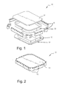
- FIGURES 1 and 2 illustrate a precision coil form 10 used for fabricating high temperature superconducting (HTS) coil.
- the HTS coil is typically layer wound with HTS tape under tension on the coil form and is epoxy-impregnated and compressed to attain close dimensional tolerances.
- HTS tape Several types of HTS tape are known, and any suitable HTS tape could be used in the manufacture of the HTS coil of the invention.
- the coil form 10 includes a racetrack-shaped bobbin 12 with substantially straight sides as shown and two side plates 14 that are disposed in facing relation surrounding the bobbin 12.
- the plates 14 may include impregnation holes (not shown) to effect post-compression epoxy impregnation of the HTS tape winding.
- a series of blocks 16 are assembled on an outer edge of the side plates 14 and are displaceable toward and away from the bobbin 12 via bolts or the like.
- the HTS tape winding is shown in FIGURE 1 at 18.
- a start lead of the coil is soldered to a lead terminal, such as a copper lead terminal or the like, that is secured to one of the side plates 14 near the center line axis of the coil.
- a layer of binder such as pre-preg filament plies or a thermoplastic material such as polyester is applied on the bobbin 12, then a first layer of the HTS tape is wound.
- the blocks 16 are bolted on the side plates 14, particularly at least the straight blocks, to compress the straight sections of the first layer against the bobbin 12 so that the first layer of tape, the pre-preg layer, and the bobbin 12 all stick together.
- a second layer of binder material (pre-preg filament plies) is applied on top of the first tape layer, then a second layer of HTS tape is wound.
- the same series of straight blocks 16 is used to compress the winding 18 against the bobbin 12 so that all the layers stick together.
- the layer winding process continues until the last odd number layer is complete, and a finish lead is soldered to a copper lead terminal that is secured to the other of the side plates 14 near the center line axis of the coil.
- a layer of pre-preg filament plies is then applied on the outside surface of the complete winding followed by a layer of copper foil with a rectangular cooling heat exchanger tube bonded on the outside surface.
- a series of straight blocks and corner blocks 16 are assembled to the outside surface of the copper foil via the side plates 16 to compress the complete coil as moderate heat is applied to precision shape the coil outside surface.
- the finished coil form and winding assembly is baked at uniform temperature to cure the pre-preg. The temperature varies according to a curing temperature of the particular material.
- the resulting coil structure is a strong winding composite built to close tolerance dimensions.
- the bolts that secure the blocks 16 to the side plates 14 may be sized to effect stepwise compression of the layers of HTS tape.
- the plurality of blocks may include blocks of different thicknesses for selective compressing according to a number of layers of the HTS tape.
- the blocks may additionally include a plurality of final blocks that are shaped according to a desired outside diameter of the superconducting coils (as shown in FIGURE 2) to effect a precisely sized coil form.
- a pre-preg coating on the HTS tape insulation is used, thereby eliminating the interlayer pre-preg filament plies.
- the resulting coil structure has higher packing factor of HTS tapes, resulting in higher winding current density.
- glass insulated HTS tape can be used with a fast curing adhesive to bond and compress each layer to the one before at discrete locations.
- the complete winding is epoxy-impregnated by a vacuum pressure impregnation process.
- the vacuum pressure impregnation process is known, and details thereof will not be provided.
- each layer of wound HTS tape can be bonded and compressed with the one before so that spring back of the tape on at least the straight sections is eliminated, thus preventing poor packing factor, reduced current density and inferior strength properties of the winding composite.
- the HTS coil fabricated with the apparatus and method of the invention results in a precision coil form that prevents high strains and potential damage to the coil during loading.
Landscapes
- Engineering & Computer Science (AREA)
- Power Engineering (AREA)
- Manufacturing & Machinery (AREA)
- Superconductive Dynamoelectric Machines (AREA)
- Manufacture Of Motors, Generators (AREA)
- Superconductors And Manufacturing Methods Therefor (AREA)
- Manufacturing Cores, Coils, And Magnets (AREA)
Abstract
Description
- The present invention relates generally to a superconductive coil in a synchronous rotating machine. More particularly, the present invention relates to an apparatus and method for manufacturing superconducting field windings in the rotor of a synchronous machine.
- Synchronous electrical machines having field coil windings include, but are not limited to, rotary generators, rotary motors, and linear motors. These machines generally comprise a stator and rotor that are electro-magnetically coupled. The rotor may include a multi-pole rotor core and coil windings mounted on the rotor core. The rotor cores may include a magnetically-permeable solid material, such as an iron-core rotor.
- Conventional copper windings are commonly used in the rotors of synchronous electrical machines. Electrical resistance of copper windings, however, is sufficient (although low by conventional measures) to contribute to substantial heating of the rotor and to diminish the power efficiency of the machine. Recently, superconducting coil windings have been developed for rotors, which have effectively no resistance and are highly advantageous rotor coil windings.
- High temperature superconducting coils used as the rotor field windings of the electrical machine must be designed as rigid structures made with precise dimensional tolerances so that the structural support can fit to the coil without excessive clearances that may result in high strain and potential damage to the coil during loading. The spring back of the tape conductor as it is wound on the straight sections of a racetrack coil form results in poor packing factor and lower strength of the composite compared to the circular sections.
- Typical superconductor rotor windings are made from saddle-shaped coils that are assembled around cylindrical shells for structural support. These saddle-shaped coils are complex winding structures that may result in overstraining the high temperature superconducting (HTS) tape conductor by the winding operation as a result of tight bend diameters, twisting of leads, and differential thermal strain of the winding relative to the support structure during cool down.
- In an exemplary embodiment of the invention, an apparatus for manufacturing HTS coils includes two side plates disposed in facing relation, a preferably racetrack-shaped bobbin disposed between the side plates that receives layers of HTS tape interposed with a binder, and a plurality of blocks assembled adjacent an outer edge of the side plates. The blocks are displaceable toward the bobbin to compress the layers of HTS tape on the bobbin. The plurality of blocks may be assembled on the outer edge of the side plates via bolts. In this context, the bolts are sized to stepwise compress the layers of HTS tape. Alternatively, the blocks may include blocks of different thicknesses for selective compressing according to a number of layers of the HTS tape. Still further, the plurality of blocks may include a plurality of final blocks that are shaped according to desired outside dimensions of the superconducting coils. The binder may be any suitable material and preferably includes pre-preg filament-ply interlayer insulation or a thermoplastic material.
- In another exemplary embodiment of the invention, a method of manufacturing HTS coils is performed with the apparatus of the invention. The method includes the steps of (a) winding HTS tape onto the bobbin, (b) applying a binder to the wound HTS tape, (c) compressing the HTS tape and the binder against the bobbin with the plurality of blocks, and (d) baking the compressed HTS tape and the binder to thereby cure the binder. Steps (a), (b) and (c) may be practiced for each layer of HTS tape. Alternatively, steps (b) and (c) may be practiced after winding multiple layers of the HTS tape. In this context, step (b) may be practiced by epoxy-impregnating the wound multiple layers of the HTS tape by a vacuum pressure impregnation process. Still further, step (a) in this context may be practiced using HTS tape with a pre-preg coating.
- The method may further include, prior to step (a), the step of securing a start lead of the coil to a lead terminal on one of the two side plates and applying a binder layer to the bobbin. In this context, prior to step (d), the method may additionally include the step of securing a finished lead of the coil to a lead terminal on the other of the two side plates, applying a layer of copper foil to the coil with a rectangular cooling heat exchanger tube bonded thereto, and repeating step (c) under heat.
- The invention will now be described in greater detail, by way of example, with reference to the drawings, in which:-
- FIGURE 1 is an assembly drawing showing the apparatus and method for manufacturing HTS racetrack coil of the invention; and
- FIGURE 2 is a perspective view of the apparatus.
-
- FIGURES 1 and 2 illustrate a
precision coil form 10 used for fabricating high temperature superconducting (HTS) coil. The HTS coil is typically layer wound with HTS tape under tension on the coil form and is epoxy-impregnated and compressed to attain close dimensional tolerances. Several types of HTS tape are known, and any suitable HTS tape could be used in the manufacture of the HTS coil of the invention. - The
coil form 10 includes a racetrack-shaped bobbin 12 with substantially straight sides as shown and twoside plates 14 that are disposed in facing relation surrounding thebobbin 12. Theplates 14 may include impregnation holes (not shown) to effect post-compression epoxy impregnation of the HTS tape winding. A series ofblocks 16 are assembled on an outer edge of theside plates 14 and are displaceable toward and away from thebobbin 12 via bolts or the like. The HTS tape winding is shown in FIGURE 1 at 18. - In manufacturing the HTS coil, a start lead of the coil is soldered to a lead terminal, such as a copper lead terminal or the like, that is secured to one of the
side plates 14 near the center line axis of the coil. A layer of binder such as pre-preg filament plies or a thermoplastic material such as polyester is applied on thebobbin 12, then a first layer of the HTS tape is wound. Theblocks 16 are bolted on theside plates 14, particularly at least the straight blocks, to compress the straight sections of the first layer against thebobbin 12 so that the first layer of tape, the pre-preg layer, and thebobbin 12 all stick together. A second layer of binder material (pre-preg filament plies) is applied on top of the first tape layer, then a second layer of HTS tape is wound. The same series ofstraight blocks 16 is used to compress the winding 18 against thebobbin 12 so that all the layers stick together. The layer winding process continues until the last odd number layer is complete, and a finish lead is soldered to a copper lead terminal that is secured to the other of theside plates 14 near the center line axis of the coil. - A layer of pre-preg filament plies is then applied on the outside surface of the complete winding followed by a layer of copper foil with a rectangular cooling heat exchanger tube bonded on the outside surface. A series of straight blocks and corner blocks 16 (as shown in FIGURE 1) are assembled to the outside surface of the copper foil via the
side plates 16 to compress the complete coil as moderate heat is applied to precision shape the coil outside surface. The finished coil form and winding assembly is baked at uniform temperature to cure the pre-preg. The temperature varies according to a curing temperature of the particular material. The resulting coil structure is a strong winding composite built to close tolerance dimensions. - In the manufacturing process, the bolts that secure the
blocks 16 to theside plates 14 may be sized to effect stepwise compression of the layers of HTS tape. In this manner, only one production set ofblocks 16 is required as the bolts enable stepwise compression of the HTS tape as the layers are formed. Alternatively, the plurality of blocks may include blocks of different thicknesses for selective compressing according to a number of layers of the HTS tape. The blocks may additionally include a plurality of final blocks that are shaped according to a desired outside diameter of the superconducting coils (as shown in FIGURE 2) to effect a precisely sized coil form. - In a variation of the winding fabrication process, a pre-preg coating on the HTS tape insulation is used, thereby eliminating the interlayer pre-preg filament plies. The resulting coil structure has higher packing factor of HTS tapes, resulting in higher winding current density. In another alternative, glass insulated HTS tape can be used with a fast curing adhesive to bond and compress each layer to the one before at discrete locations. Subsequently, the complete winding is epoxy-impregnated by a vacuum pressure impregnation process. The vacuum pressure impregnation process is known, and details thereof will not be provided.
- With the structure and method of the present invention, each layer of wound HTS tape can be bonded and compressed with the one before so that spring back of the tape on at least the straight sections is eliminated, thus preventing poor packing factor, reduced current density and inferior strength properties of the winding composite. The HTS coil fabricated with the apparatus and method of the invention results in a precision coil form that prevents high strains and potential damage to the coil during loading.
- For the sake of good order, various aspects of the invention are set out in the following clauses: -
- 1. An apparatus for manufacturing high temperature superconducting
(HTS) coils, the apparatus comprising:
- two side plates (14) disposed in facing relation;
- a bobbin (12) disposed between the side plates, the bobbin receiving layers of HTS tape (18) interposed with a binder; and a plurality of blocks (16) assembled adjacent an outer edge of the side plates, the blocks being displaceable toward the bobbin to compress the layers of HTS tape on the bobbin.
- 2. An apparatus according to clause 1, wherein the plurality of blocks (16) are assembled on the outer edge of the side plates (14) via bolts.
- 3. An apparatus according to clause 2, wherein the bolts are sized to stepwise compress the layers of HTS tape (18).
- 4. An apparatus according to clause 2, wherein the plurality of blocks (16) comprise blocks of different thicknesses for selective compressing according to a number of layers of the HTS tape (18).
- 5. An apparatus according to clause 2, wherein the plurality of blocks (16) comprise a plurality of final blocks that are shaped according to desired outside dimensions of the superconducting coils.
- 6. An apparatus according to clause 1, wherein the binder comprises pre-preg filament-ply interlayer insulation.
- 7. An apparatus according to clause 1, wherein the binder comprises a thermoplastic material.
- 8. An apparatus according to clause 1, wherein the bobbin (12) is racetrack shaped with substantially straight sides.
- 9. A method of manufacturing high temperature superconducting (HTS)
coils with an apparatus including two side plates (14) disposed in facing
relation, a bobbin (12) disposed between the side plates, and a plurality of
blocks (16) assembled adjacent an outer edge of the side plates, the blocks
being displaceable toward and away from the bobbin, the method comprising
- (a) winding HTS tape (18) onto the bobbin (12);
- (b) applying a binder to the wound HTS tape (18);
- (c) compressing the HTS tape and the binder against the bobbin (12) with the plurality of blocks (16); and
- (d) baking the compressed HTS tape and the binder to thereby cure the binder.
- 10. A method according to clause 9, wherein steps (a), (b) and (c) are practiced for each layer of the HTS tape (18).
- 11. A method according to clause 9, wherein steps (b) and (c) are practiced after winding multiple layers of the HTS tape (18).
- 12. A method according to clause 11, wherein step (b) is practiced by epoxy-impregnating the wound multiple layers of the HTS tape (18) by a vacuum pressure impregnation process.
- 13. A method according to clause 11, wherein step (a) is practiced using HTS tape (18) with a pre-preg coating.
- 14. A method according to clause 9, further comprising, prior to step (a), the step of securing a start lead of the coil to a lead terminal on one of the two side plates, and applying a binder layer to the bobbin (12).
- 15. A method according to
clause 14, further comprising, prior to step (d), the step of securing a finish lead of the coil to a lead terminal on the other of the two side plates (14), applying a layer of copper foil to the coil with a rectangular cooling heat exchanger tube bonded thereto, and repeating step (c) under heat. - 16. A method according to clause 9, wherein the bobbin (12) is racetrack shaped with substantially straight sides, and wherein step (c) is practiced by compressing the HTS tape (18) and the binder against the straight sides of the bobbin.
- 17. A method of manufacturing high temperature superconducting (HTS)
coils, the method comprising:
- (a) winding HTS tape (18) onto a bobbin (12);
- (b) applying a binder to the wound HTS tape;
- (c) compressing the HTS tape and the binder; and
- (d) baking the compressed HTS tape and the binder to thereby cure the binder.
-
Claims (10)
- An apparatus for manufacturing high temperature superconducting (HTS) coils, the apparatus comprising:two side plates (14) disposed in facing relation;a bobbin (12) disposed between the side plates, the bobbin receiving layers of HTS tape (18) interposed with a binder; and
a plurality of blocks (16) assembled adjacent an outer edge of the side plates, the blocks being displaceable toward the bobbin to compress the layers of HTS tape on the bobbin. - An apparatus according to claim 1, wherein the plurality of blocks (16) are assembled on the outer edge of the side plates (14) via bolts.
- An apparatus according to claim 2, wherein the bolts are sized to stepwise compress the layers of HTS tape (18).
- An apparatus according to claim 2, wherein the plurality of blocks (16) comprise blocks of different thicknesses for selective compressing according to a number of layers of the HTS tape (18).
- An apparatus according to claim 2, wherein the plurality of blocks (16) comprise a plurality of final blocks that are shaped according to desired outside dimensions of the superconducting coils.
- A method of manufacturing high temperature superconducting (HTS) coils with an apparatus including two side plates (14) disposed in facing relation, a bobbin (12) disposed between the side plates, and a plurality of blocks (16) assembled adjacent an outer edge of the side plates, the blocks being displaceable toward and away from the bobbin, the method comprising(a) winding HTS tape (18) onto the bobbin (12);(b) applying a binder to the wound HTS tape (18);(c) compressing the HTS tape and the binder against the bobbin (12) with the plurality of blocks (16); and(d) baking the compressed HTS tape and the binder to thereby cure the binder.
- A method according to claim 6, wherein steps (a), (b) and (c) are practiced for each layer of the HTS tape (18).
- A method according to claim 6, wherein steps (b) and (c) are practiced after winding multiple layers of the HTS tape (18).
- A method according to claim 8, wherein step (b) is practiced by epoxy-impregnating the wound multiple layers of the HTS tape (18) by a vacuum pressure impregnation process.
- A method of manufacturing high temperature superconducting (HTS) coils, the method comprising:(a) winding HTS tape (18) onto a bobbin (12);(b) applying a binder to the wound HTS tape;(c) compressing the HTS tape and the binder; and(d) baking the compressed HTS tape and the binder to thereby cure the binder.
Applications Claiming Priority (2)
| Application Number | Priority Date | Filing Date | Title |
|---|---|---|---|
| US854464 | 1997-05-12 | ||
| US09/854,464 US6922885B2 (en) | 2001-05-15 | 2001-05-15 | High temperature superconducting racetrack coil |
Publications (2)
| Publication Number | Publication Date |
|---|---|
| EP1261112A2 true EP1261112A2 (en) | 2002-11-27 |
| EP1261112A3 EP1261112A3 (en) | 2004-03-03 |
Family
ID=25318765
Family Applications (1)
| Application Number | Title | Priority Date | Filing Date |
|---|---|---|---|
| EP02253375A Withdrawn EP1261112A3 (en) | 2001-05-15 | 2002-05-14 | Method and apparatus for manufacturing a high temperature superconducting coil |
Country Status (11)
| Country | Link |
|---|---|
| US (1) | US6922885B2 (en) |
| EP (1) | EP1261112A3 (en) |
| JP (1) | JP4111745B2 (en) |
| KR (1) | KR100897651B1 (en) |
| CN (1) | CN1311617C (en) |
| BR (1) | BR0201804B1 (en) |
| CA (1) | CA2384593C (en) |
| CZ (1) | CZ20021669A3 (en) |
| MX (1) | MXPA02004839A (en) |
| NO (1) | NO331254B1 (en) |
| PL (1) | PL199881B1 (en) |
Cited By (2)
| Publication number | Priority date | Publication date | Assignee | Title |
|---|---|---|---|---|
| WO2004075383A1 (en) * | 2003-02-14 | 2004-09-02 | American Superconductor Corporation | A rotor assembly |
| WO2017042543A1 (en) * | 2015-09-09 | 2017-03-16 | Tokamak Energy Ltd | Hts magnet sections |
Families Citing this family (16)
| Publication number | Priority date | Publication date | Assignee | Title |
|---|---|---|---|---|
| US7547999B2 (en) | 2003-04-28 | 2009-06-16 | General Electric Company | Superconducting multi-pole electrical machine |
| DE102004043988B3 (en) * | 2004-09-11 | 2006-05-11 | Bruker Biospin Gmbh | Superconductive magnet coil arrangement |
| KR100723236B1 (en) * | 2006-02-13 | 2007-05-29 | 두산중공업 주식회사 | Superconducting Coil Assembly with Improved Cooling Performance |
| JP2009177103A (en) * | 2008-01-28 | 2009-08-06 | Sumitomo Electric Ind Ltd | Superconducting coil and superconducting coil winding frame |
| CN101692367B (en) * | 2009-09-28 | 2011-07-27 | 西部超导材料科技有限公司 | Preparation method of Nb3Sn superconducting magnet with improved fracture resistance |
| CN102412640B (en) * | 2011-12-05 | 2014-04-02 | 中国东方电气集团有限公司 | Offshore type superconducting wind power generator |
| KR101445034B1 (en) * | 2013-05-02 | 2014-10-30 | 두산엔진주식회사 | Super conducting electric power generation system |
| KR101501478B1 (en) * | 2013-05-14 | 2015-03-18 | 두산중공업 주식회사 | Superconducting coil assembly, manufacturing method thereof, and rotor of superconducting rorating machine having the same |
| CN103295719B (en) * | 2013-06-26 | 2016-06-15 | 南京梅山冶金发展有限公司 | A kind of strong magnetomechanical magnetizing coil and preparation method thereof |
| KR101649291B1 (en) | 2014-10-20 | 2016-08-18 | 고려대학교 산학협력단 | Superconducting coils using partial insulation winding technique and manufacturing method thereof |
| KR101681414B1 (en) | 2015-04-24 | 2016-11-30 | 두산중공업 주식회사 | Method of winding a superconducting coil |
| RU2632474C2 (en) * | 2016-03-24 | 2017-10-05 | Российская Федерация, от имени которой выступает Государственная корпорация по атомной энергии "Росатом" | Method for manufacturing racetrack winding from current-conducting tape |
| RU169041U1 (en) * | 2016-09-09 | 2017-03-02 | Федеральное государственное бюджетное образовательное учреждение высшего образования "Московский авиационный институт (национальный исследовательский университет)" | SUPERCONDUCTIVE SYNCHRONOUS ELECTRIC MACHINE |
| CN108461248B (en) * | 2018-02-08 | 2022-10-25 | 中国电力科学研究院有限公司 | Composite superconductor coil |
| CN113257515B (en) * | 2021-07-12 | 2021-09-28 | 四川大学 | High-temperature superconducting double-pancake coil and winding and fixing method thereof |
| JP2024042587A (en) * | 2022-09-15 | 2024-03-28 | 株式会社東芝 | Superconducting rotating electric machine coil and its manufacturing method |
Citations (1)
| Publication number | Priority date | Publication date | Assignee | Title |
|---|---|---|---|---|
| JPH05284730A (en) * | 1992-04-01 | 1993-10-29 | Mitsubishi Electric Corp | Assembling method of superconducting coil device |
Family Cites Families (29)
| Publication number | Priority date | Publication date | Assignee | Title |
|---|---|---|---|---|
| US3665595A (en) * | 1968-10-31 | 1972-05-30 | Tohoku University The | Method of manufacturing superconductive materials |
| US3713211A (en) * | 1971-05-03 | 1973-01-30 | Union Carbide Corp | Method of fabricating a superconducting magnet |
| US4279944A (en) | 1978-12-26 | 1981-07-21 | General Electric Company | Epoxy impregnated ventilated winding |
| US5102483A (en) * | 1989-02-27 | 1992-04-07 | Jgc Corporation | Method for production of elongated ceramic sheets |
| US5187859A (en) * | 1990-08-23 | 1993-02-23 | The United States Of America As Represented By The United States Department Of Energy | Method of preloading superconducting coils by using materials with different thermal expansion coefficients |
| US5173678A (en) * | 1990-09-10 | 1992-12-22 | Gte Laboratories Incorporated | Formed-to-shape superconducting coil |
| US5293524A (en) * | 1992-10-15 | 1994-03-08 | The United States Of America As Represented By The Department Of Energy | Uniformly wound superconducting coil and method of making same |
| EP0631331B1 (en) * | 1993-05-10 | 1998-03-11 | Sumitomo Electric Industries, Limited | Method of preparing high-temperature superconducting wire |
| US5434129A (en) * | 1993-09-23 | 1995-07-18 | Advanced Superconductors, Inc. | Method for manufacturing high tc superconductor coils |
| US5504984A (en) * | 1993-12-13 | 1996-04-09 | Sumitomo Electric Industries, Ltd. | Methods of manufacturing Nb3 Al superconducting wire and coil |
| US5531015A (en) | 1994-01-28 | 1996-07-02 | American Superconductor Corporation | Method of making superconducting wind-and-react coils |
| US5548168A (en) | 1994-06-29 | 1996-08-20 | General Electric Company | Superconducting rotor for an electrical machine |
| US5625548A (en) | 1994-08-10 | 1997-04-29 | American Superconductor Corporation | Control circuit for cryogenically-cooled power electronics employed in power conversion systems |
| US5672921A (en) | 1995-03-13 | 1997-09-30 | General Electric Company | Superconducting field winding assemblage for an electrical machine |
| US5532663A (en) | 1995-03-13 | 1996-07-02 | General Electric Company | Support structure for a superconducting coil |
| US5758405A (en) * | 1995-04-28 | 1998-06-02 | American Superconductor Corporation | Consumable mandrel for superconducting magnetic coils |
| JP3658844B2 (en) * | 1996-03-26 | 2005-06-08 | 住友電気工業株式会社 | Oxide superconducting wire, manufacturing method thereof, and oxide superconducting stranded wire and conductor using the same |
| US5777420A (en) | 1996-07-16 | 1998-07-07 | American Superconductor Corporation | Superconducting synchronous motor construction |
| US6173577B1 (en) | 1996-08-16 | 2001-01-16 | American Superconductor Corporation | Methods and apparatus for cooling systems for cryogenic power conversion electronics |
| US5774032A (en) | 1996-08-23 | 1998-06-30 | General Electric Company | Cooling arrangement for a superconducting coil |
| US6397454B1 (en) * | 1996-09-26 | 2002-06-04 | American Superconductor Corp. | Decoupling of superconducting elements in high temperature superconducting composites |
| KR100276003B1 (en) * | 1998-09-30 | 2000-12-15 | 윤덕용 | Apparatus for forming thin film on a tape-type substrate and method for forming the same |
| US6066906A (en) | 1999-02-17 | 2000-05-23 | American Superconductor Corporation | Rotating machine having superconducting windings |
| US6140719A (en) | 1999-02-17 | 2000-10-31 | American Superconductor Corporation | High temperature superconducting rotor for a synchronous machine |
| US6509819B2 (en) * | 1999-07-23 | 2003-01-21 | American Superconductor Corporation | Rotor assembly including superconducting magnetic coil |
| US6444917B1 (en) * | 1999-07-23 | 2002-09-03 | American Superconductor Corporation | Encapsulated ceramic superconductors |
| DE19943783A1 (en) | 1999-09-13 | 2001-03-29 | Siemens Ag | Superconducting device with a multi-pole winding arrangement |
| US6169353B1 (en) | 1999-09-28 | 2001-01-02 | Reliance Electric Technologies, Llc | Method for manufacturing a rotor having superconducting coils |
| US6420842B1 (en) | 2000-01-11 | 2002-07-16 | American Superconductor Corporation | Exciter and electronic regulator for rotating machinery |
-
2001
- 2001-05-15 US US09/854,464 patent/US6922885B2/en not_active Expired - Lifetime
-
2002
- 2002-05-02 CA CA2384593A patent/CA2384593C/en not_active Expired - Fee Related
- 2002-05-14 CZ CZ20021669A patent/CZ20021669A3/en unknown
- 2002-05-14 EP EP02253375A patent/EP1261112A3/en not_active Withdrawn
- 2002-05-14 KR KR1020020026320A patent/KR100897651B1/en not_active Expired - Fee Related
- 2002-05-14 NO NO20022299A patent/NO331254B1/en not_active IP Right Cessation
- 2002-05-14 BR BRPI0201804-7A patent/BR0201804B1/en not_active IP Right Cessation
- 2002-05-14 MX MXPA02004839A patent/MXPA02004839A/en active IP Right Grant
- 2002-05-15 CN CNB02120117XA patent/CN1311617C/en not_active Expired - Fee Related
- 2002-05-15 JP JP2002139398A patent/JP4111745B2/en not_active Expired - Fee Related
- 2002-05-15 PL PL353914A patent/PL199881B1/en unknown
Patent Citations (1)
| Publication number | Priority date | Publication date | Assignee | Title |
|---|---|---|---|---|
| JPH05284730A (en) * | 1992-04-01 | 1993-10-29 | Mitsubishi Electric Corp | Assembling method of superconducting coil device |
Cited By (6)
| Publication number | Priority date | Publication date | Assignee | Title |
|---|---|---|---|---|
| WO2004075383A1 (en) * | 2003-02-14 | 2004-09-02 | American Superconductor Corporation | A rotor assembly |
| CN100574061C (en) * | 2003-02-14 | 2009-12-23 | 美国超导体公司 | Rotor assembly |
| WO2017042543A1 (en) * | 2015-09-09 | 2017-03-16 | Tokamak Energy Ltd | Hts magnet sections |
| RU2686524C1 (en) * | 2015-09-09 | 2019-04-29 | Токемек Энерджи Лтд | Hts-magnetic sections |
| US10930837B2 (en) | 2015-09-09 | 2021-02-23 | Tokamak Energy Ltd | HTS magnet sections |
| US11575078B2 (en) | 2015-09-09 | 2023-02-07 | Tokamak Energy Ltd | HTS magnet sections |
Also Published As
| Publication number | Publication date |
|---|---|
| KR20020090861A (en) | 2002-12-05 |
| CA2384593A1 (en) | 2002-11-15 |
| PL353914A1 (en) | 2002-11-18 |
| JP2003037970A (en) | 2003-02-07 |
| CA2384593C (en) | 2011-12-13 |
| MXPA02004839A (en) | 2004-12-13 |
| NO331254B1 (en) | 2011-11-07 |
| CZ20021669A3 (en) | 2003-02-12 |
| US20020170166A1 (en) | 2002-11-21 |
| US6922885B2 (en) | 2005-08-02 |
| CN1311617C (en) | 2007-04-18 |
| KR100897651B1 (en) | 2009-05-14 |
| JP4111745B2 (en) | 2008-07-02 |
| EP1261112A3 (en) | 2004-03-03 |
| BR0201804B1 (en) | 2013-02-19 |
| NO20022299L (en) | 2002-11-18 |
| NO20022299D0 (en) | 2002-05-14 |
| BR0201804A (en) | 2003-03-11 |
| PL199881B1 (en) | 2008-11-28 |
| CN1385951A (en) | 2002-12-18 |
Similar Documents
| Publication | Publication Date | Title |
|---|---|---|
| CA2384593C (en) | High temperature superconducting racetrack coil | |
| JP3953813B2 (en) | Rotor assembly with superconducting magnetic coil | |
| US20100181860A1 (en) | Method for making electrical windings for electrical machines and winding obtained by said method | |
| US7863795B2 (en) | Method for producing a conductor bar of transposed stranded conductors | |
| JP2001525653A (en) | High voltage rotating electric machine | |
| JP4376869B2 (en) | Rotor assembly | |
| US6912773B2 (en) | Method of forming a winding disc for an axial field electrical machine | |
| ZA200108545B (en) | Improvements in electrical machines. | |
| US12278535B2 (en) | Slotless rotating electric machine | |
| WO2011040982A1 (en) | "brushless motor-generator" | |
| CN212784942U (en) | Coil transposition structure for permanent magnet motor and permanent magnet motor with same | |
| US12395053B1 (en) | High voltage conductor and methods of fabrication | |
| Goldstein et al. | Design of a Compact Stator Winding in an Axial-Flux Permanent Magnet Machine for Aerospace Applications | |
| CN119602548A (en) | A method for manufacturing a slotless magnetic component and a slotless magnetic component | |
| CN121663843A (en) | A stator structure and method for a shielded electric motor | |
| JP2025153326A (en) | Insulating tape and rotating electrical machines | |
| JPH02288309A (en) | Superconducting coil | |
| JPH09312218A (en) | Conductor winding | |
| JPS58207603A (en) | Resin-mold coil |
Legal Events
| Date | Code | Title | Description |
|---|---|---|---|
| PUAI | Public reference made under article 153(3) epc to a published international application that has entered the european phase |
Free format text: ORIGINAL CODE: 0009012 |
|
| AK | Designated contracting states |
Kind code of ref document: A2 Designated state(s): AT BE CH CY DE DK ES FI FR GB GR IE IT LI LU MC NL PT SE TR |
|
| AX | Request for extension of the european patent |
Free format text: AL;LT;LV;MK;RO;SI |
|
| PUAL | Search report despatched |
Free format text: ORIGINAL CODE: 0009013 |
|
| AK | Designated contracting states |
Kind code of ref document: A3 Designated state(s): AT BE CH CY DE DK ES FI FR GB GR IE IT LI LU MC NL PT SE TR |
|
| AX | Request for extension of the european patent |
Extension state: AL LT LV MK RO SI |
|
| 17P | Request for examination filed |
Effective date: 20040903 |
|
| AKX | Designation fees paid |
Designated state(s): AT BE CH CY DE DK ES FI FR GB GR IE IT LI LU MC NL PT SE TR |
|
| 17Q | First examination report despatched |
Effective date: 20100610 |
|
| GRAP | Despatch of communication of intention to grant a patent |
Free format text: ORIGINAL CODE: EPIDOSNIGR1 |
|
| INTG | Intention to grant announced |
Effective date: 20190219 |
|
| STAA | Information on the status of an ep patent application or granted ep patent |
Free format text: STATUS: THE APPLICATION IS DEEMED TO BE WITHDRAWN |
|
| 18D | Application deemed to be withdrawn |
Effective date: 20190702 |