EP1261099A2 - Low-energy storage fast-start uninterruptible power supply system and method - Google Patents
Low-energy storage fast-start uninterruptible power supply system and method Download PDFInfo
- Publication number
- EP1261099A2 EP1261099A2 EP02253516A EP02253516A EP1261099A2 EP 1261099 A2 EP1261099 A2 EP 1261099A2 EP 02253516 A EP02253516 A EP 02253516A EP 02253516 A EP02253516 A EP 02253516A EP 1261099 A2 EP1261099 A2 EP 1261099A2
- Authority
- EP
- European Patent Office
- Prior art keywords
- alternator
- flywheel
- motion transmitting
- power grid
- heat engine
- Prior art date
- Legal status (The legal status is an assumption and is not a legal conclusion. Google has not performed a legal analysis and makes no representation as to the accuracy of the status listed.)
- Granted
Links
Images
Classifications
-
- H—ELECTRICITY
- H02—GENERATION; CONVERSION OR DISTRIBUTION OF ELECTRIC POWER
- H02J—ELECTRIC POWER NETWORKS; CIRCUIT ARRANGEMENTS OR SYSTEMS FOR SUPPLYING OR DISTRIBUTING ELECTRIC POWER; SYSTEMS FOR STORING ELECTRIC ENERGY
- H02J3/00—Circuit arrangements for AC mains or AC distribution networks
- H02J3/28—Arrangements for balancing of the load in networks by storage of energy
- H02J3/30—Arrangements for balancing of the load in networks by storage of energy using dynamo-electric machines coupled to flywheels
-
- H—ELECTRICITY
- H02—GENERATION; CONVERSION OR DISTRIBUTION OF ELECTRIC POWER
- H02J—ELECTRIC POWER NETWORKS; CIRCUIT ARRANGEMENTS OR SYSTEMS FOR SUPPLYING OR DISTRIBUTING ELECTRIC POWER; SYSTEMS FOR STORING ELECTRIC ENERGY
- H02J9/00—Circuit arrangements for emergency or stand-by power supply, e.g. for emergency lighting
-
- H—ELECTRICITY
- H02—GENERATION; CONVERSION OR DISTRIBUTION OF ELECTRIC POWER
- H02J—ELECTRIC POWER NETWORKS; CIRCUIT ARRANGEMENTS OR SYSTEMS FOR SUPPLYING OR DISTRIBUTING ELECTRIC POWER; SYSTEMS FOR STORING ELECTRIC ENERGY
- H02J9/00—Circuit arrangements for emergency or stand-by power supply, e.g. for emergency lighting
- H02J9/04—Circuit arrangements for emergency or stand-by power supply, e.g. for emergency lighting in which the distribution system is disconnected from the normal source and connected to a standby source
- H02J9/06—Circuit arrangements for emergency or stand-by power supply, e.g. for emergency lighting in which the distribution system is disconnected from the normal source and connected to a standby source with automatic change-over, e.g. UPS systems
- H02J9/08—Circuit arrangements for emergency or stand-by power supply, e.g. for emergency lighting in which the distribution system is disconnected from the normal source and connected to a standby source with automatic change-over, e.g. UPS systems requiring starting of a prime-mover
-
- Y—GENERAL TAGGING OF NEW TECHNOLOGICAL DEVELOPMENTS; GENERAL TAGGING OF CROSS-SECTIONAL TECHNOLOGIES SPANNING OVER SEVERAL SECTIONS OF THE IPC; TECHNICAL SUBJECTS COVERED BY FORMER USPC CROSS-REFERENCE ART COLLECTIONS [XRACs] AND DIGESTS
- Y02—TECHNOLOGIES OR APPLICATIONS FOR MITIGATION OR ADAPTATION AGAINST CLIMATE CHANGE
- Y02B—CLIMATE CHANGE MITIGATION TECHNOLOGIES RELATED TO BUILDINGS, e.g. HOUSING, HOUSE APPLIANCES OR RELATED END-USER APPLICATIONS
- Y02B70/00—Technologies for an efficient end-user side electric power management and consumption
- Y02B70/30—Systems integrating technologies related to power network operation and communication or information technologies for improving the carbon footprint of the management of residential or tertiary loads, i.e. smart grids as climate change mitigation technology in the buildings sector, including also the last stages of power distribution and the control, monitoring or operating management systems at local level
-
- Y—GENERAL TAGGING OF NEW TECHNOLOGICAL DEVELOPMENTS; GENERAL TAGGING OF CROSS-SECTIONAL TECHNOLOGIES SPANNING OVER SEVERAL SECTIONS OF THE IPC; TECHNICAL SUBJECTS COVERED BY FORMER USPC CROSS-REFERENCE ART COLLECTIONS [XRACs] AND DIGESTS
- Y02—TECHNOLOGIES OR APPLICATIONS FOR MITIGATION OR ADAPTATION AGAINST CLIMATE CHANGE
- Y02E—REDUCTION OF GREENHOUSE GAS [GHG] EMISSIONS, RELATED TO ENERGY GENERATION, TRANSMISSION OR DISTRIBUTION
- Y02E60/00—Enabling technologies; Technologies with a potential or indirect contribution to GHG emissions mitigation
- Y02E60/16—Mechanical energy storage, e.g. flywheels or pressurised fluids
-
- Y—GENERAL TAGGING OF NEW TECHNOLOGICAL DEVELOPMENTS; GENERAL TAGGING OF CROSS-SECTIONAL TECHNOLOGIES SPANNING OVER SEVERAL SECTIONS OF THE IPC; TECHNICAL SUBJECTS COVERED BY FORMER USPC CROSS-REFERENCE ART COLLECTIONS [XRACs] AND DIGESTS
- Y04—INFORMATION OR COMMUNICATION TECHNOLOGIES HAVING AN IMPACT ON OTHER TECHNOLOGY AREAS
- Y04S—SYSTEMS INTEGRATING TECHNOLOGIES RELATED TO POWER NETWORK OPERATION, COMMUNICATION OR INFORMATION TECHNOLOGIES FOR IMPROVING THE ELECTRICAL POWER GENERATION, TRANSMISSION, DISTRIBUTION, MANAGEMENT OR USAGE, i.e. SMART GRIDS
- Y04S20/00—Management or operation of end-user stationary applications or the last stages of power distribution; Controlling, monitoring or operating thereof
- Y04S20/20—End-user application control systems
Definitions
- the present invention generally relates to a backup system for a utility power grid and, more particularly, is concerned with an uninterruptible power supply (UPS) system and method having a fast-start capability and a low-energy storage requirement.
- UPS uninterruptible power supply
- a conventional UPS system normally includes a DC-AC inverter, transfer switches, an energy storage unit, oftentimes using massive lead acid batteries, and, in many cases, an alternator driven by a heat engine.
- DC power from the energy storage unit usually batteries
- the transfer switches During a fault in the dual-fed grid source, DC power from the energy storage unit (usually batteries) is converted to the proper AC voltage, current, and frequency and connected to the critical loads via the transfer switches.
- many of the conventional UPS systems rated to provide critical power for long periods of time, have a heat engine and an alternator in addition to the battery energy storage unit. In these conventional UPS systems, the battery energy storage unit is required to provide the electrical power to the critical load until the heat engine is cranked and started and the alternator has achieved a stabilized output.
- the present invention provides an uninterruptible power supply (UPS) system and method designed to satisfy the aforementioned need.
- UPS uninterruptible power supply
- the UPS system of the present invention has a fast-start capability that greatly reduces the duration of rated power required to be supplied by an energy storage unit and thus eliminates the need to use massive lead acid batteries in the energy storage unit of the UPS system.
- an uninterruptible power supply system having a standby mode of operation and a backup mode of operation which includes a heat engine having a crankshaft, an alternator having an input shaft and an output electrically connected to an electrical power grid, a flywheel disposed between the heat engine crankshaft and alternator input shaft, a first motion transmitting mechanism disposed between the flywheel and heat engine crankshaft and actuatable between engaged and disengaged conditions for correspondingly drivingly coupling and decoupling the flywheel to and from the heat engine crankshaft, a second motion transmitting mechanism providing a one-way drive coupling between the flywheel and alternator input shaft, a third motion transmitting mechanism disposed between the flywheel and alternator input shaft and actuatable between engaged and disengaged conditions for correspondingly drivingly coupling and decoupling the flywheel to and from the alternator input shaft, a source of AC electrical energy connected to the electrical power grid, and an uninterruptible power supply system control connected to the electrical power grid and to the heat engine
- the second motion transmitting mechanism provides the one-way drive coupling such that in a first direction (a first polarity of torque) from the alternator to flywheel the second motion transmitting mechanism operates in an overrun mode in which the alternator input shaft can rotate at a speed faster than that of the flywheel whereas in a second direction (a second polarity of torque), opposite the first direction, from the flywheel to alternator the second motion transmitting mechanism is operates in a locked mode in which the flywheel can rotate up to the same speed as that of the alternator input shaft.
- a first direction a first polarity of torque
- the second motion transmitting mechanism When the third motion transmitting mechanism is in the disengaged condition the second motion transmitting mechanism permits the alternator input shaft to overrun the flywheel such that no driving motion is transmitted from the alternator input shaft to the flywheel whereas when the third motion transmitting mechanism is in the engaged condition drive torque can be transmitted in either direction between the flywheel and alternator input shaft so that the alternator input shaft and flywheel can rotate at the same speed.
- a method of operating an uninterruptible power supply system comprising the steps of operating the system in a standby mode by maintaining the system electrically connected to a power grid in a state of readiness to change to a backup mode in response to detecting a fault in the power grid, and operating the system in the backup mode by supplying electrical power to the power grid sufficient to overcome the power loss caused by the detected fault and to rotate a heat engine of the system up to a speed where the heat engine can be started and accelerated to full operation by introduction of a fuel energy source independent of the power grid.
- UPS uninterruptible power supply
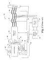
- the prior art UPS system 10 of FIG. 1 includes a heat engine 12, an alternator 14, a flywheel 16 mounted on a crankshaft 18 of the heat engine 12, a motion transmitting mechanism 20 disposed between the flywheel 16 and an alternator input shaft 22 and actuatable for coupling the flywheel to and from the input shaft 22 of the alternator 14, a starter or cranking motor 24, gearing 26 drivingly coupling the cranking motor 24 to the flywheel 16 and a cranking battery 28 connected to the cranking motor 24.
- the cranking battery 28 for example, can be a 12V or 24V battery.
- the prior art UPS system 10 also includes an energy storage unit 30, a DC-AC inverter 32 connected to the energy storage unit 30, and first and second transfer switches 34, 36, such as 3-phase contactors.
- the transfer switches 34, 36 are operable for connecting and disconnecting the alternator 14 and/or the DC-AC inverter 32 to and from a utility grid 38.
- the prior art UPS system 10 further includes a UPS system control 40 for detecting a fault in response to a given loss of power on the utility grid 38. In response to detection of the fault, the UPS system control 40 controls the operation of the first and second transfer switches 34, 36, the cranking motor 24 and a fuel injector 42 of the heat engine 12.
- the UPS system control 40 immediately issues a command to the energy storage unit 30 to input DC electrical energy to the DC-AC inverter 32 and also closes the second transfer switch 36 which connects only the inverter 32, and not the alternator 14, to the utility grid 38.
- An alternate technique is for the inverter 32 to be connected to the energy storage unit 30 , prior to the fault, i.e., maintaining the energy storage unit 30 at a full state of charge which thereby allows the second transfer switch 36 to be closed prior to the detection of the fault.
- the inverter 32 converts DC electrical energy from the energy storage unit 30 to AC electrical energy of the proper voltage, current and frequency to supply power to the utility grid 38 via the second transfer switch 36.
- the UPS system control 40 also issues a command to the cranking motor 24 to crank the flywheel 16 via gearing 26 and thus crank the crankshaft 18 of the heat engine 12.
- the electrical energy to rotate the flywheel 16 via the cranking motor 24 and gearing 26 is provided to the cranking motor 24 by the cranking battery 28.
- the UPS system control 40 enables the fuel injector 42 to start the heat engine 12.
- the fuel to the heat engine 12 is regulated to continue to accelerate the heat engine 12 and thus the alternator 14 to the speed that is required to generate the proper frequency for the critical load of the utility grid 38. For example, if a 4-pole synchronous alternator 14 is used, the synchronous speed is 1800 rpm. Alternators of alternate configuration also are in use. These include different numbers of poles, synchronous machines (wound field, permanent magnet, etc.), asynchronous or induction machines, and high speed alternators coupled to the heat engine 12 via a speed multiplier or reducer.
- a time duration of at least fifteen seconds is disadvantageously required to start the heat engine driven alternator 14 and stabilize the electrical output of the alternator 14 prior to connecting the alternator 14 to the utility grid 38 via the first and second transfer switches 34, 36.
- the energy storage unit 30 supplies all of the electrical energy to the utility grid 38.
- the first transfer switch 34 is closed and the heat engine driven alternator 14 supplies the critical load.
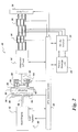
- the low energy storage fast-start UPS system 44 there is illustrated one embodiment of the low energy storage fast-start UPS system of the present invention, generally designated 44.
- Many components of the low energy storage fast-start UPS system 44 are generally similar to those of the prior art UPS system 10 which have been described above. These components, identified by the same reference numerals, are the heat engine 12, alternator 14, DC-AC inverter 32, first and second transfer switches 34, 36, UPS system control 40 and fuel injector 42.
- the low energy storage fast-start UPS system 44 does not employ the cranking motor 24, gearing 26 and cranking battery 28 and does not have a flywheel 16 attached directly to the crankshaft 18 of the heat engine 12.
- the low energy storage fast-start UPS system 44 includes a relatively large inertial flywheel 46, first, second and third motion transmitting mechanisms 48, 50, 52 associated with the flywheel 46, and an energy storage unit 54 with similar peak power rating as the energy storage unit 30 of FIG. 1 but with a significant lower value of stored electrical energy.
- first and third motion transmitting mechanisms 48, 52 are friction clutches 48, 52 while the second motion transmitting mechanism 50 is a one-way overrun clutch 50.
- the motion transmitting mechanisms 48, 50, 52 can be any other suitable devices which will perform functions that are substantially the same as those performed by the first, second and third clutches 48, 50, 52 which will now be described.
- the first clutch 48 is actuatable between engaged and disengaged conditions for correspondingly drivingly coupling and decoupling the flywheel 46 to and from the crankshaft 18 of the heat engine 12.
- the first clutch 48 in the engaged condition is capable of transmitting drive torque in either direction between the flywheel 46 and heat engine 12. More particularly, the first clutch 48 is disposed between the flywheel 46 and the crankshaft 18 of the heat engine 12 and includes a low inertial disk part 56 which is attached to the crankshaft 18 of the heat engine 12 and a pressure plate part 58 which is attached to the inertial flywheel 46.
- the flywheel 46 is coupled to and decoupled from the crankshaft 18 of the heat engine 12 when the disk part 56 and pressure plate part 58 of the first clutch 48 are respectively engaged with and disengaged from one another in the corresponding engaged and disengaged conditions of the first clutch 48.
- Engagement and disengagement of clutches 48 and 52 include conventional methods incorporating either mechanical springs and actuators or electrical clutching techniques.
- the second clutch 50 provides a one-way drive coupling between the flywheel 46 and the input shaft 22 of the alternator 14.
- the second clutch 50 In the alternator-to-flywheel direction, the second clutch 50 is operable in an overrun mode in which the input shaft 22 of the alternator 14 is permitted to rotate faster than the flywheel 46 whereas when torque is applied to increase the speed of the flywheel 46, with respect to the alternator 14, the second clutch 50 is operable in a locked mode in which the flywheel 46 rotates at the same speed as that of the input shaft 22 of the alternator 14.
- the second clutch 50 can only transmit drive torque in the flywheel-to-alternator direction and when in the locked mode.
- the second clutch 50 is disposed between the flywheel 46 and the input shaft 22 of the alternator 14 and includes an outer annular part 60 attached to the flywheel 46 and an inner annular part 62 attached to the alternator input shaft 22.
- the one-way drive coupling between the outer annular part 60 and inner annular part 62 of the second clutch 50 is provided such that the inner annular part 62 of the second clutch 50 rotating with the input shaft 22 of the alternator 14 can rotate faster than the outer annular part 62 of the second clutch 50 rotating with the flywheel 46 but the outer annular part 60 of the second clutch 50 cannot rotate faster than the inner annular part 62 of the second clutch 50.
- the third clutch 52 is actuatable between engaged and disengaged conditions for correspondingly drivingly coupling and decoupling the flywheel 46 (via the outer annular part 60 of the second clutch 52) to and from the input shaft 22 of the alternator 14.
- the third clutch 52 in the engaged condition is capable of transmitting drive torque in either direction between the flywheel 46 and alternator 14. More particularly, the third clutch 52 is disposed between the flywheel 46 and the input shaft 22 of the alternator 14 and includes a disk part 64 attached to the alternator shaft 22.
- the outer annular part 60 of the second clutch 50 and a pressure plate part 66 are attached to the flywheel 46.
- the third clutch 52 When the third clutch 52 is in the disengaged condition, its disk part 64 and pressure plate part 66 are disengaged from one another and thus the second clutch 50 provides the only coupling between the flywheel 46 and the alternator input shaft 22 as described previously.
- the third clutch 52 When the third clutch 52 is in an engaged condition, its disk part 64 and pressure plate part 66 are engaged with one another and thus the third clutch 52 couples the flywheel 46 and input shaft 22 of the alternator 14 to one another such that drive torque can be transmitted in either.
- the third clutch 52 in effect, overrides the overrun mode of operation of second clutch 50 in which the second clutch 50 by itself cannot transmit drive torque from the input shaft 22 of the alternator 14 to the flywheel 46.
- the low energy storage fast-start system 44 of the present invention is normally in a standby mode of operation in the absence of the detection of a power failure or fault and is changed to a backup mode of operation only by detection of a grid power failure or fault.
- the first and second transfer switches 34, 36 are both closed.
- the output of the alternator 14 is electrically connected to the utility grid 38 and AC electrical energy from the utility grid 38 is applied to the alternator 14, causing rotation of the input shaft 22 thereof at the desired synchronous speed, that being 1800 rpm in the case of a 4-pole synchronous alternator and a 60 Hz utility grid.
- the 60 Hz AC electrical power from the utility grid 38 is applied to the DC-AC (3-phase) inverter 32.
- the inverter 32 and UPS system control 40 are operational to keep the energy storage unit 54 at a prescribed relatively high state of charge.
- the third clutch 52 is closed during the standby mode, overriding the overrun mode of the second clutch 50, such that the flywheel 46 is driven by the input shaft 22 of the alternator 14 to rotate at the synchronous speed of 1800 rpm also.
- the first clutch 48 is in the disengaged condition and thus the heat engine 12 is stationary and thereby its crankshaft is not rotating as no torque is being transmitted by the first clutch 48 from the synchronously rotating flywheel 46 to the crankshaft 18 of the heat engine 12.
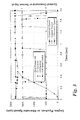
- FIG. 3 there is illustrated a graph of a timing sequence of the UPS system 44 for understanding the operation thereof.
- a "Grid Power OK" signal transitions from a logic level 1 to a logic level 0, changing the UPS system 44 from the standby mode to backup mode.
- Uninterrupted power flows to a critical load on the utility grid 38 from the DC-AC inverter 32 using the power provided by the energy storage unit 54.
- the third clutch (C3) 52 is actuated to a disengaged condition by a command signal (logic level 1 to logic level 0 transition) received from the UPS system control 40, followed by actuation of the first clutch (C1) 48 to an engaged condition by another command signal (logic level 0 to logic level 1 transition) received from the UPS system control 40.
- the first clutch (C1) 48 transmits drive torque from the relatively high inertia flywheel 46 to the low inertia crankshaft 18 of the heat engine 12 such that the rotational speed of the crankshaft 18 of the heat engine 12 accelerates rapidly as the rotational speed of the flywheel 46 decreases below the speed of the input shaft 22 of the alternator 14, causing the inner annular part 62 of the second clutch 50 to overrun the outer annular part 60 thereof because during the entire starting sequence of the heat engine 12 the alternator 14 continues to rotate at the synchronous speed which is faster than the now decreasing speed of the flywheel 46.
- the fuel injector 42 is enabled by a command signal (logic level 0 to logic level 1 transition) received from the UPS system control 40 and the heat engine 12 starts and continues to accelerate toward the synchronous speed.
- a command signal logic level 0 to logic level 1 transition
- the second clutch 50 assumes its locked mode in which the outer annular part 60 of the second clutch 50 locks up with the inner annular part 62 thereof such that the outer annular part 60 is transmitting drive torque to the inner annular part 62 and thus they rotate in unison with one another.
- the third clutch (C3) 52 is actuated to the engaged condition by receipt of a command signal (logic level 0 to logic level 1 transition) from the UPS system control 40 and the heat engine 12 is thus also drivingly coupled by the third clutch (C3) 52 to the input shaft 22 of the alternator 14 and the heat engine driven alternator 14 thereby provides the critical power to the utility grid 38.
- the UPS system 44 changes back to the standby mode in which the fuel injector 42 is disabled by a command signal (logic level 1 to logic level 0 transition) received from the UPS system control 40, followed by the UPS system control 40 sending a command signal (logic level 1 to logic level 0 transition) to the first clutch (C1) 48 to actuate it to the disengaged condition, causing the heat engine 12 to stop abruptly.
- FIG. 3 also shows that the heat engine driven alternator 14 of the UPS system 44 provides the needed power output to the utility grid 38 in less than one second. When compared to the fifteen seconds in the case of the prior art UPS system 10, this is at least a factor of ten reduction in response time. Thus, for a one MW UPS system, the required energy storage is only approximately 417 W-h.
- the low energy storage fast-start system 44 of the present invention is normally is in a standby mode of operation and is changed to a backup mode of operation only by detection of a grid power failure or fault.
- the alternator 14 is constantly electrically connected to the grid 38 and rotating at the synchronous speed (1800 rpm, for example) so that the backup mode capability is in a constant state of readiness in the event of a grid failure.
- the inverter 32 and energy storage unit 54 remain electrically coupled to the utility grid 38 in the standby mode of operation of the system 44 so that the energy storage unit 54 maintains its charge and is ready to immediately supply the necessary power when the system 44 is changed to the backup mode of operation.
- the transfer switches 34, 36 between the utility grid 38 and the alternator 14 are closed during both standby and backup modes of operation and only are opened during testing of the system 44.
- the first clutch 48 is in the disengaged condition and the flywheel 46 is thus decoupled from the heat engine 12.
- the third clutch 52 is actuated to the engaged condition and the input shaft 22 of the alternator 14 thus rotatably drives the flywheel 46 via the third clutch 52.
- the third clutch 52 is actuated to the disengaged condition and following disengagement of clutch 52, the first clutch 48 is actuated to the engaged condition coupling the flywheel 46 to the crankshaft 18 of the heat engine 12 which permits the second clutch 50 to allow the flywheel 46 to decrease in speed as the flywheel 46 transfers torque via the engaged first clutch 48 to the crankshaft 18 of the heat engine 12 to initiate and cause an increase of its speed of rotation up to the level where the heat engine 12 is started.
- UPS system 44 can include those in emerging mission-critical power systems industry.
- Alternate environmentally friendly energy storage devices which can be used include high specific power ultracapacitors, high specific power flywheels, and high specific power batteries.
Landscapes
- Engineering & Computer Science (AREA)
- Power Engineering (AREA)
- Business, Economics & Management (AREA)
- Emergency Management (AREA)
- Stand-By Power Supply Arrangements (AREA)
- Control Of Vehicle Engines Or Engines For Specific Uses (AREA)
- Control Of Eletrric Generators (AREA)
Abstract
Description
Claims (10)
- An uninterruptible power supply system (44) having a standby mode of operation and a backup mode of operation, said system (44) comprising:a heat engine (12) having a crankshaft (18);an alternator (14) having an input shaft (22) and an output electrically connected to an electrical power grid (38);a flywheel (46) disposed between said crankshaft (18) of said heat engine (12) and said input shaft (22) of said alternator (14);a first motion transmitting mechanism (48) disposed between said flywheel (46) and said crankshaft (18) of said heat engine (12) and actuatable between engaged and disengaged conditions for correspondingly drivingly coupling and decoupling said flywheel (46) to and from said crankshaft (18) of said heat engine (12);a second motion transmitting mechanism (50) providing a one-way drive coupling between said flywheel (46) and said input shaft (22) of said alternator (14) such that in a first direction from said alternator (14) to said flywheel (46) said second motion transmitting mechanism (50) operates in an overrun mode in which said input shaft (22) of said alternator (14) can rotate at a speed faster than that of said flywheel (46) whereas in a second direction, opposite said first direction, from said flywheel (46) to said alternator (14) said second motion transmitting mechanism (50) operates in a locked mode in which said flywheel (46) can rotate up to the same speed as that of said input shaft (22) of the alternator (14) so as to transmit drive torque from said flywheel (46) to said alternator (14);a third motion transmitting mechanism (52) disposed between said flywheel (46) and said input shaft (22) of said alternator (14) and actuatable between engaged and disengaged conditions for correspondingly drivingly coupling and decoupling said flywheel (46) to and from said input shaft (22) of said alternator (14) such that when said third motion transmitting mechanism (52) is in said disengaged condition said second motion transmitting mechanism (50) permits said input shaft (22) of said alternator (14) to overrun said flywheel (46) such that no driving torque is transmitted from said input shaft (22) of said alternator (14) to said flywheel (46) whereas when said third motion transmitting mechanism (52) is in said engaged condition said input shaft (22) of said alternator (14) and said flywheel (46) are drivingly coupled to one another such that said drive torque can be transmitted in either direction between said flywheel (46) and input shaft (22) of said alternator (14) so that said input shaft (22) of said alternator 914) and said flywheel (46) can rotate at the same speed;a source (54, 32) of AC electrical energy connected to the electrical power grid (38); andan uninterruptible power supply system control (40) connected to the electrical power grid (38) and to said heat engine (12) and said first and third motion transmitting mechanisms (48, 52) for controlling operation of said heat engine (12) and said first and third motion transmitting mechanisms (48, 52) so as to change said system (44) from a standby mode of operation to a backup mode of operation such that in said standby mode said source (54, 32) of AC electrical energy is charging and ready to supply power to the power grid (38) and said first and third motion transmitting mechanisms (48, 52) are respectively in disengaged and engaged conditions so as to transmit alternator rotary motion to said flywheel (46) but not therefrom to said heat engine (12), whereas in said backup mode said source (54, 32) of AC electrical energy is supplying power to the power grid (38) in response to said control (40) detecting of a fault in the power grid (38) and said first and third motion transmitting mechanisms (48, 52) are respectively in engaged and disengaged conditions so as to permit said alternator (14), via said second motion transmitting mechanism (50), to overrun said flywheel (46) and allow transmitting of flywheel torque to accelerate said heat engine (12) to a starting speed for driving said alternator (14) to supply the power to the power grid (38).
- The system (44) of claim 1 in which in absence of said control (40) detecting a fault in the power grid (38), said control (40) is operable to maintain said system (44) in said standby mode of operation such that said alternator (14) rotates at said predetermined speed so as to be in a constant state of readiness for facilitating starting of said heat engine (12) in response to said control (40) changing said system (44) from said standby mode to said backup mode.
- The system (44) of claim 1 in which in absence of said control (40) detecting a fault in the power grid (38), said source (54, 32) of AC electrical energy remains coupled to the power grid (38) to receive electrical energy therefrom so as to be charged and ready to supply electrical energy to the power grid (38) upon said control (40) changing said system (44) from said standby mode to said backup mode.
- The system (44) of claim 1 in which in absence of said control (40) detecting a fault in the power grid (38), said control (40) is operable to maintain said system (44) in said standby mode of operation in which said first motion transmitting mechanism (48) is maintained in said disengaged condition such that said flywheel (46) is decoupled from said heat engine (12).
- The system (44) of claim 1 in which in absence of said control (40) detecting a fault in the power grid (38), said control (40) is operable to maintain said system (44) in said standby mode of operation in which said third motion transmitting mechanism (52) is maintained in said engaged condition such that said input shaft (22) of said alternator (14) rotatably drives said flywheel (46) via said third motion transmitting mechanism (52).
- The system (44) of claim 1 in which in response to said control (40) detecting a fault in the power grid (38), said control (40) is operable to change said system (44) from said standby mode of operation to said backup mode of operation in which said control (40) actuates said third motion transmitting mechanism (52) to said disengaged condition.
- The system (44) of claim 1 in which said first and third motion transmitting mechanisms (48, 52) are friction clutches and said second motion transmitting mechanism (50) is a one-way overrun clutch.
- A method of operating an uninterruptible power supply system (44), comprising the steps of:operating an uninterruptible power supply system in a standby mode by maintaining the system (44) electrically connected to a power grid (38) in a state of readiness to change to a backup mode in response to detecting a fault in the power grid (38); andoperating the system (44) in the backup mode by supplying electrical power to the power grid (38) sufficient to overcome the power loss caused by the detected fault and to rotate a heat engine (12) of the system (44) up to a speed where the heat engine (12) can be started and accelerated to full operation by introduction of a fuel energy from a source (42) independent of the power grid (38).
- The method of claim 8 in which operating the system (44) in the standby mode includes charging a source (54, 32) of AC electrical energy by applying electrical energy to the source (54, 32) from the power grid (38).
- The method of claim 8 in which operating the system (44) in the standby mode includes connecting an alternator (14) to the power grid (38) and applying power to the alternator (14) so as to cause rotation thereof at synchronous speed.
Applications Claiming Priority (2)
| Application Number | Priority Date | Filing Date | Title |
|---|---|---|---|
| US09/681,697 US6507128B2 (en) | 2001-05-23 | 2001-05-23 | Low-energy storage fast-start uninterruptible power supply system and method |
| US681697 | 2001-05-23 |
Publications (3)
| Publication Number | Publication Date |
|---|---|
| EP1261099A2 true EP1261099A2 (en) | 2002-11-27 |
| EP1261099A3 EP1261099A3 (en) | 2005-08-17 |
| EP1261099B1 EP1261099B1 (en) | 2007-12-19 |
Family
ID=24736388
Family Applications (1)
| Application Number | Title | Priority Date | Filing Date |
|---|---|---|---|
| EP02253516A Expired - Lifetime EP1261099B1 (en) | 2001-05-23 | 2002-05-20 | Low-energy storage fast-start uninterruptible power supply system and method |
Country Status (5)
| Country | Link |
|---|---|
| US (2) | US6507128B2 (en) |
| EP (1) | EP1261099B1 (en) |
| JP (1) | JP3872720B2 (en) |
| KR (1) | KR100687988B1 (en) |
| CA (1) | CA2385706C (en) |
Cited By (3)
| Publication number | Priority date | Publication date | Assignee | Title |
|---|---|---|---|---|
| EP2790291A1 (en) * | 2013-04-08 | 2014-10-15 | Siemens Aktiengesellschaft | Uninterruptable power supply and emergency standby power system |
| EP3416885A4 (en) * | 2016-02-18 | 2019-10-16 | National Oilwell Varco Norway AS | SYSTEM OF REGENERATION AND DISTRIBUTION OF ENERGY |
| IT201800010232A1 (en) * | 2018-11-12 | 2020-05-12 | Pr Ind S R L | Hybrid generator set. |
Families Citing this family (64)
| Publication number | Priority date | Publication date | Assignee | Title |
|---|---|---|---|---|
| DE10047755B4 (en) * | 2000-09-27 | 2011-03-31 | Daimler Ag | Starter-generator apparatus for internal combustion engines and method for operating the device |
| US6777823B1 (en) * | 2001-05-21 | 2004-08-17 | Active Power, Inc. | Integrated continuous power system assemblies having multiple nozzle block segments |
| US6507128B2 (en) * | 2001-05-23 | 2003-01-14 | General Electric Company | Low-energy storage fast-start uninterruptible power supply system and method |
| US7786616B2 (en) * | 2003-02-07 | 2010-08-31 | Cummins Power Generation Inc. | Generator with DC boost and split bus bidirectional DC-to-DC converter for uninterruptible power supply system or for enhanced load pickup |
| US20040155527A1 (en) * | 2003-02-10 | 2004-08-12 | Bryde Jan Henrik | Distributed power generation, conversion, and storage system |
| US20060017328A1 (en) * | 2003-02-10 | 2006-01-26 | Bryde Jan H | Control system for distributed power generation, conversion, and storage system |
| US7088011B2 (en) * | 2003-11-21 | 2006-08-08 | Smith Raymond W | Motor-generator system with a current control feedback loop |
| US7042108B2 (en) * | 2004-02-06 | 2006-05-09 | Otto Farkas | Backup power system |
| US7504737B2 (en) | 2004-02-18 | 2009-03-17 | Linda A. Vasilovich | Method and apparatus for converting human power to electrical power |
| CA2555673A1 (en) * | 2004-02-18 | 2005-09-01 | Guy W. Vasilovich | Method and apparatus for converting human power to electrical power |
| US20050184594A1 (en) * | 2004-02-20 | 2005-08-25 | Fredette Steven J. | Electric storage augmentation of fuel cell response to AC system transients |
| CA2617922C (en) * | 2005-08-05 | 2015-05-12 | Power Group International, Inc. | Batteryless starter for ups |
| DE102005039461A1 (en) * | 2005-08-20 | 2007-03-15 | Daimlerchrysler Ag | Hybrid powertrain of a motor vehicle and method of operating a hybrid powertrain |
| US7568537B2 (en) * | 2006-01-09 | 2009-08-04 | General Electric Company | Vehicle propulsion system |
| US7489048B2 (en) | 2006-01-09 | 2009-02-10 | General Electric Company | Energy storage system for electric or hybrid vehicle |
| US7780562B2 (en) * | 2006-01-09 | 2010-08-24 | General Electric Company | Hybrid vehicle and method of assembling same |
| US7595597B2 (en) * | 2006-01-18 | 2009-09-29 | General Electric Comapany | Vehicle propulsion system |
| US20080054827A1 (en) * | 2006-08-29 | 2008-03-06 | Derek States | Power system rating converter |
| US7710081B2 (en) * | 2006-10-27 | 2010-05-04 | Direct Drive Systems, Inc. | Electromechanical energy conversion systems |
| US7750518B1 (en) | 2006-11-29 | 2010-07-06 | Active Power, Inc. | Transient energy systems and methods for use of the same |
| US7425807B1 (en) | 2006-11-29 | 2008-09-16 | Active Power, Inc. | Transient energy systems and methods for use of the same |
| US7400052B1 (en) * | 2006-11-29 | 2008-07-15 | Active Power, Inc. | Transient energy systems and methods for use of the same |
| US7642664B1 (en) | 2006-11-29 | 2010-01-05 | Active Power, Inc. | Transient energy systems and methods for use of the same |
| US20080297120A1 (en) * | 2006-12-12 | 2008-12-04 | Honeywell International, Inc. | Electronically redundant spacecraft power and attitude control system |
| US20080143302A1 (en) * | 2006-12-18 | 2008-06-19 | Regen Technologies, Inc. | Electrical power generation system |
| DE102006061889B3 (en) * | 2006-12-28 | 2008-03-27 | Siemens Ag | Method for detection of optimum emergency operation function for engine of vehicle, involves forming engine with device, where torque or rotational speed of engine is limited by developing error indication |
| JP5231745B2 (en) * | 2007-02-19 | 2013-07-10 | 本田技研工業株式会社 | Cogeneration equipment |
| KR100778892B1 (en) * | 2007-02-23 | 2007-11-22 | 성신전기공업(주) | Power supply method of uninterruptible power supply and uninterruptible power supply |
| CN101765959B (en) * | 2007-05-08 | 2015-04-15 | 美国电力转换有限公司 | AC Power Energy Management |
| DE102007030055B4 (en) * | 2007-06-29 | 2010-01-28 | Enocean Gmbh | Energy converter, counter with energy converter, device with counter, method for converting mechanical into electrical energy, and counting method |
| US7573144B1 (en) * | 2008-02-07 | 2009-08-11 | Direct Drive Systems, Inc. | Reconfigurable power system using multiple phase-set electric machines |
| EP2245518A4 (en) * | 2008-02-15 | 2013-04-17 | Hewlett Packard Development Co | Changing power states of data handling devices to meet redundancy criterion |
| US7961449B2 (en) * | 2008-03-17 | 2011-06-14 | Robert Bosch Gmbh | Extended controller keep alive system and method |
| US20090323256A1 (en) | 2008-06-25 | 2009-12-31 | Errera Michael R | Interface for system for generating electric power |
| US8040007B2 (en) * | 2008-07-28 | 2011-10-18 | Direct Drive Systems, Inc. | Rotor for electric machine having a sleeve with segmented layers |
| US8013548B2 (en) * | 2008-10-14 | 2011-09-06 | General Electric Company | System, vehicle and related method |
| US8203316B2 (en) * | 2008-12-18 | 2012-06-19 | Hamilton Sundstrand Corporation | Eddy current torsional damper for generator |
| US20100304920A1 (en) * | 2009-05-28 | 2010-12-02 | Bernard Joseph Simon | Hybrid Assembly , A Hybrid Power-Train , And A Method For Operating A Selectively Movable Assembly |
| CN101902056B (en) * | 2009-06-01 | 2015-06-17 | Ge医疗系统环球技术有限公司 | Uninterruptable power supply and method for saving electricity of same |
| US8287078B2 (en) | 2010-07-23 | 2012-10-16 | Xerox Corporation | Inkjet printing system having environmentally responsive thermal control mode |
| EP2640594A2 (en) * | 2010-11-17 | 2013-09-25 | BRUSA Elektronik AG | Energy supply unit for an electric vehicle and electric vehicle |
| US9118213B2 (en) | 2010-11-24 | 2015-08-25 | Kohler Co. | Portal for harvesting energy from distributed electrical power sources |
| FR2969424B1 (en) * | 2010-12-21 | 2015-01-02 | Ge Energy Products France Snc | ELECTRIC PRODUCTION SYSTEM |
| EP2555141A1 (en) * | 2011-08-03 | 2013-02-06 | Alcatel Lucent | A method, a system, a server, a control element, a computer program and a computer program product for operating a power grid having decentralized control elements |
| US8627914B2 (en) | 2011-11-10 | 2014-01-14 | Arc Energy Recovery, Inc. | Energy recovery drive system and vehicle with energy recovery drive system |
| CN102562285B (en) * | 2012-01-28 | 2017-02-22 | 蒙国宁 | Practical, simple and reliable grid-connected power generation unit utilizing small-size oilfield associated gas |
| US9020721B2 (en) * | 2012-12-04 | 2015-04-28 | Fca Us Llc | Real time modeling of engine load addition due to alternator with an over-run clutch |
| TWI478468B (en) * | 2013-01-28 | 2015-03-21 | Jun Dong Power Corp | Power generator |
| EP2818649B1 (en) * | 2013-06-27 | 2017-09-06 | Enrichment Technology Company Ltd. | Combination power plant |
| US20150115902A1 (en) * | 2013-10-29 | 2015-04-30 | General Electric Company | Power generation system and method with fault ride through capability |
| US9577471B2 (en) * | 2014-02-13 | 2017-02-21 | Power Group International Corporation | Power system for providing an uninterruptible power supply to an external load |
| CN105337542B (en) * | 2014-08-07 | 2018-07-10 | 上海得司能源科技发展有限公司 | Strong magnetic alternation wind energy tidal time difference machine system and electricity-generating method |
| US10135293B2 (en) | 2015-04-01 | 2018-11-20 | Isolated Parallel Inc | Direct current isolated-parallel uninterruptible power supply system |
| CN104821607B (en) * | 2015-05-15 | 2017-03-15 | 东北大学 | A kind of photovoltaic micro Power balance control method based on three end Collaborative Control |
| KR101663976B1 (en) | 2015-07-21 | 2016-10-11 | 주식회사 지오닉스 | power supply with 3dimension seismic isolator |
| US20170203666A1 (en) * | 2016-01-19 | 2017-07-20 | Ford Global Technologies, Llc | Battery charging system and servicing method |
| US12362566B2 (en) * | 2016-09-19 | 2025-07-15 | Flexgen Power Systems, Llc | Systems and methods for rapid activation and synchronization of dispatchable power sources |
| CN106992533A (en) * | 2017-05-20 | 2017-07-28 | 吴钦发 | A kind of voltage stabilization and frequency stabilization no-break power unit and the power supply method for realizing uninterrupted power source voltage stabilization and frequency stabilization |
| US11770047B2 (en) | 2018-03-09 | 2023-09-26 | Alexey TYSHKO | Power grid stabilization system utilizing two generators mechanically linked via continuous variable transmission |
| BE1026574B1 (en) * | 2018-08-28 | 2020-03-30 | Euro Diesel S A | Method of supplying an electrical appliance with direct current and accumulator of electrical energy |
| US10900540B1 (en) | 2019-11-01 | 2021-01-26 | Phos Global Energy Solutions, Inc. | Mechanical renewable green energy production |
| US10749372B1 (en) * | 2019-11-01 | 2020-08-18 | 3B Energy, Llc | Mechanical renewable green energy production |
| CN111591304B (en) * | 2020-05-31 | 2021-09-03 | 北京泓慧国际能源技术发展有限公司 | Health monitoring system and method of UPS power supply vehicle |
| CN119030166B (en) * | 2024-08-30 | 2025-02-25 | 国家能源集团江苏电力有限公司 | A gravity energy storage system based on mechanically coupled flywheel |
Family Cites Families (40)
| Publication number | Priority date | Publication date | Assignee | Title |
|---|---|---|---|---|
| GB679831A (en) * | 1949-05-20 | 1952-09-24 | Standard Telephones Cables Ltd | Improvements in or relating to electrical power supply equipment |
| DE1143220B (en) * | 1960-01-13 | 1963-02-07 | Voith Gmbh J M | Method for operating a gearbox with overrunning clutches, especially for rail locomotives |
| US3558901A (en) * | 1969-02-24 | 1971-01-26 | Charles J Jacobus | Standby power system |
| US3675112A (en) * | 1970-07-09 | 1972-07-04 | Dynamics Corp America | Standby power system |
| DE2153464A1 (en) * | 1971-10-27 | 1973-05-03 | Kloeckner Humboldt Deutz Ag | IMMEDIATE RESERVE AGGREGATE |
| US4233858A (en) * | 1976-12-27 | 1980-11-18 | The Garrett Corporation | Flywheel drive system having a split electromechanical transmission |
| SE424232B (en) * | 1979-02-14 | 1982-07-05 | Sab Ind Ab | SET TO MUTE CABLES WITH A ROTATING SYSTEM |
| US4309620A (en) * | 1979-12-03 | 1982-01-05 | Calspan Corporation | Flywheel electric transmission apparatus |
| WO1982000928A1 (en) * | 1980-09-02 | 1982-03-18 | P Jefferies | Electric drive train for a vehicle |
| US4439720A (en) * | 1981-01-23 | 1984-03-27 | Societe Aman | Units for generating constant-frequency alternating electric energy with substitute driving means |
| US4460834A (en) * | 1983-08-29 | 1984-07-17 | Power Group International Corp. | Uninterruptible power system |
| US4629947A (en) * | 1985-04-03 | 1986-12-16 | Hammerslag Julius G | Electric vehicle drive system |
| US4857755A (en) * | 1988-09-27 | 1989-08-15 | Comstock W Kenneth | Constant power system and method |
| US5267110A (en) * | 1991-03-19 | 1993-11-30 | International Business Machines Corporation | Rotary actuator for a direct access storage device |
| US5285111A (en) * | 1993-04-27 | 1994-02-08 | General Motors Corporation | Integrated hybrid transmission with inertia assisted launch |
| PT101400A (en) * | 1993-11-08 | 1995-06-30 | Fab Apare Precisao Electro Pot | POWER SUPPLY WITHOUT HYBRID ALTERNATE CURRENT INTERRUPTING |
| US6177734B1 (en) * | 1998-02-27 | 2001-01-23 | Isad Electronic Systems Gmbh & Co. Kg | Starter/generator for an internal combustion engine, especially an engine of a motor vehicle |
| SE505214C2 (en) * | 1995-09-04 | 1997-07-14 | Chandur Sadarangani | hybrid Drive |
| US5821630A (en) * | 1995-11-13 | 1998-10-13 | Schutten; Herman P. | Flywheel-speed sensing for control of an emergency-power engine |
| JP3454036B2 (en) * | 1995-11-13 | 2003-10-06 | トヨタ自動車株式会社 | Hybrid drive |
| US5646458A (en) * | 1996-02-22 | 1997-07-08 | Atlas Energy Systems, Inc. | Uninterruptible power system with a flywheel-driven source of standby power |
| ES2113314B1 (en) * | 1996-04-12 | 1999-01-01 | Hart Monetic S A | UNINTERRUPTED ELECTRIC POWER SUPPLY SYSTEM. |
| US5982045A (en) * | 1996-04-19 | 1999-11-09 | Toyota Jidosha Kabushiki Kaisha | Hybrid vehicle drive system adapted to prevent concurrent mode change and transmission shifting or torque distribution ratio change |
| US5767637A (en) * | 1996-05-02 | 1998-06-16 | Chrysler Corporation | Controller for turboal ternator |
| DE19645943A1 (en) * | 1996-11-07 | 1998-05-14 | Bosch Gmbh Robert | Starter unit for an internal combustion engine |
| DE19715468C1 (en) * | 1997-04-14 | 1998-10-01 | Piller Gmbh | System for stabilizing a power supply network |
| US5994794A (en) * | 1997-05-09 | 1999-11-30 | Active Power, Inc. | Methods and apparatus for providing protection to batteries in an uninterruptible power supply |
| US6020657A (en) * | 1997-08-27 | 2000-02-01 | Perfect Power Inc. | Power supply for providing instantaneous energy during utility power outages |
| JP3775012B2 (en) * | 1997-08-29 | 2006-05-17 | アイシン・エィ・ダブリュ株式会社 | Hybrid drive device for vehicle |
| US6133716A (en) * | 1998-10-23 | 2000-10-17 | Statordyne, Inc. | High-efficiency high-power uninterrupted power system |
| US6255743B1 (en) * | 1999-05-26 | 2001-07-03 | Active Power, Inc. | Method and apparatus for providing an uninterruptible supply of electric power to a critical load |
| WO2001028065A1 (en) * | 1999-10-08 | 2001-04-19 | Piller Gmbh | Device for providing an uninterrupted supply of power comprising an electrical machine and a flywheel |
| US6239513B1 (en) * | 2000-02-24 | 2001-05-29 | Design Power Solutions International | Emergency supplemental power supply for outage protection of critical electric loads |
| US6281595B1 (en) | 2000-09-25 | 2001-08-28 | General Electric Company | Microturbine based power generation system and method |
| DE10047755B4 (en) * | 2000-09-27 | 2011-03-31 | Daimler Ag | Starter-generator apparatus for internal combustion engines and method for operating the device |
| US7071581B2 (en) * | 2001-01-31 | 2006-07-04 | Satcon Technology Corp. | Uninterruptible power supply system using a slip-ring, wound-rotor-type induction machine and a method for flywheel energy storage |
| US6563229B2 (en) * | 2001-04-18 | 2003-05-13 | Otto Farkas | Standby power system |
| US6507128B2 (en) * | 2001-05-23 | 2003-01-14 | General Electric Company | Low-energy storage fast-start uninterruptible power supply system and method |
| US6437533B1 (en) | 2001-08-08 | 2002-08-20 | Buehler Motor, Inc. | Actuator position control with inductive sensing |
| US6844706B2 (en) * | 2002-08-30 | 2005-01-18 | Active Power, Inc. | Multiple path variable speed constant frequency device having automatic power path selection capability |
-
2001
- 2001-05-23 US US09/681,697 patent/US6507128B2/en not_active Expired - Lifetime
-
2002
- 2002-05-09 CA CA002385706A patent/CA2385706C/en not_active Expired - Fee Related
- 2002-05-20 EP EP02253516A patent/EP1261099B1/en not_active Expired - Lifetime
- 2002-05-22 JP JP2002146988A patent/JP3872720B2/en not_active Expired - Fee Related
- 2002-05-22 KR KR1020020028291A patent/KR100687988B1/en not_active Expired - Fee Related
- 2002-11-06 US US10/287,869 patent/US7129593B2/en not_active Expired - Lifetime
Cited By (4)
| Publication number | Priority date | Publication date | Assignee | Title |
|---|---|---|---|---|
| EP2790291A1 (en) * | 2013-04-08 | 2014-10-15 | Siemens Aktiengesellschaft | Uninterruptable power supply and emergency standby power system |
| EP3416885A4 (en) * | 2016-02-18 | 2019-10-16 | National Oilwell Varco Norway AS | SYSTEM OF REGENERATION AND DISTRIBUTION OF ENERGY |
| US11453297B2 (en) | 2016-02-18 | 2022-09-27 | National Oilwell Vareo Norway AS | System for energy regeneration and distribution |
| IT201800010232A1 (en) * | 2018-11-12 | 2020-05-12 | Pr Ind S R L | Hybrid generator set. |
Also Published As
| Publication number | Publication date |
|---|---|
| EP1261099A3 (en) | 2005-08-17 |
| KR20020090142A (en) | 2002-11-30 |
| CA2385706A1 (en) | 2002-11-23 |
| US6507128B2 (en) | 2003-01-14 |
| US20020175660A1 (en) | 2002-11-28 |
| JP3872720B2 (en) | 2007-01-24 |
| KR100687988B1 (en) | 2007-02-27 |
| JP2003009429A (en) | 2003-01-10 |
| CA2385706C (en) | 2008-12-16 |
| US7129593B2 (en) | 2006-10-31 |
| EP1261099B1 (en) | 2007-12-19 |
| US20030102672A1 (en) | 2003-06-05 |
Similar Documents
| Publication | Publication Date | Title |
|---|---|---|
| EP1261099B1 (en) | Low-energy storage fast-start uninterruptible power supply system and method | |
| JPS61500099A (en) | continuous power supply system | |
| US5811960A (en) | Battery-less uninterruptable sequel power supply | |
| US9577471B2 (en) | Power system for providing an uninterruptible power supply to an external load | |
| US7071581B2 (en) | Uninterruptible power supply system using a slip-ring, wound-rotor-type induction machine and a method for flywheel energy storage | |
| US8598722B2 (en) | Electrical generator | |
| US7566990B2 (en) | Power systems and methods using an induction generator in cooperation with an uninterruptible power supply | |
| US20020167234A1 (en) | Standby power system | |
| US20080143302A1 (en) | Electrical power generation system | |
| US10855141B2 (en) | Power supply system for providing power to a load and for start-up of an internal combustion engine that provides power to such load | |
| JPH01313626A (en) | Driving device for turbocharger equipped with rotary electric machine | |
| CN112290659A (en) | A flywheel energy storage system front power automatic switching system and method | |
| WO2025208939A1 (en) | Engine starting method and system, controller, storage medium and hybrid electric vehicle | |
| US11788499B2 (en) | Uninterruptible power supply system with engine start-up | |
| JP7742451B1 (en) | Engine-driven power generating device and engine-driven power generating system | |
| EP3939142B1 (en) | Power supply system and system for providing start-up of engines used in such power supply system | |
| US12294238B2 (en) | Uninterruptible power supply system with engine start-up | |
| JP2006067670A (en) | Control method of flywheel type uninterruptible power supply and uninterruptible power supply using the same | |
| Finehout | An uninterruptible, stable power supply for critical loads | |
| JPH0734903A (en) | Turbine starting device and starting method | |
| CN1051466A (en) | Uninterrupted power supply(ups) with gas turbine as power | |
| WO2022015617A1 (en) | Uninterruptible power supply system with engine start-up | |
| JPH1169894A (en) | Emergency gas turbine starter | |
| JPS62196027A (en) | Service interruption free electric source | |
| JPS63290136A (en) | Remote monitoring system for power generation equipment |
Legal Events
| Date | Code | Title | Description |
|---|---|---|---|
| PUAI | Public reference made under article 153(3) epc to a published international application that has entered the european phase |
Free format text: ORIGINAL CODE: 0009012 |
|
| AK | Designated contracting states |
Kind code of ref document: A2 Designated state(s): AT BE CH CY DE DK ES FI FR GB GR IE IT LI LU MC NL PT SE TR |
|
| AX | Request for extension of the european patent |
Free format text: AL;LT;LV;MK;RO;SI |
|
| RIC1 | Information provided on ipc code assigned before grant |
Ipc: 7H 02J 9/06 B Ipc: 7H 02J 9/08 A |
|
| PUAL | Search report despatched |
Free format text: ORIGINAL CODE: 0009013 |
|
| AK | Designated contracting states |
Kind code of ref document: A3 Designated state(s): AT BE CH CY DE DK ES FI FR GB GR IE IT LI LU MC NL PT SE TR |
|
| AX | Request for extension of the european patent |
Extension state: AL LT LV MK RO SI |
|
| 17P | Request for examination filed |
Effective date: 20060217 |
|
| AKX | Designation fees paid |
Designated state(s): CH FR GB IT LI |
|
| REG | Reference to a national code |
Ref country code: DE Ref legal event code: 8566 |
|
| GRAP | Despatch of communication of intention to grant a patent |
Free format text: ORIGINAL CODE: EPIDOSNIGR1 |
|
| GRAS | Grant fee paid |
Free format text: ORIGINAL CODE: EPIDOSNIGR3 |
|
| GRAA | (expected) grant |
Free format text: ORIGINAL CODE: 0009210 |
|
| AK | Designated contracting states |
Kind code of ref document: B1 Designated state(s): CH FR GB IT LI |
|
| REG | Reference to a national code |
Ref country code: GB Ref legal event code: FG4D |
|
| REG | Reference to a national code |
Ref country code: CH Ref legal event code: EP |
|
| REG | Reference to a national code |
Ref country code: CH Ref legal event code: NV Representative=s name: SERVOPATENT GMBH Ref country code: CH Ref legal event code: PFA Owner name: GENERAL ELECTRIC COMPANY Free format text: GENERAL ELECTRIC COMPANY#1 RIVER ROAD#SCHENECTADY, NY 12345 (US) -TRANSFER TO- GENERAL ELECTRIC COMPANY#1 RIVER ROAD#SCHENECTADY, NY 12345 (US) |
|
| ET | Fr: translation filed | ||
| PLBE | No opposition filed within time limit |
Free format text: ORIGINAL CODE: 0009261 |
|
| STAA | Information on the status of an ep patent application or granted ep patent |
Free format text: STATUS: NO OPPOSITION FILED WITHIN TIME LIMIT |
|
| 26N | No opposition filed |
Effective date: 20080922 |
|
| PGFP | Annual fee paid to national office [announced via postgrant information from national office to epo] |
Ref country code: FR Payment date: 20120607 Year of fee payment: 11 Ref country code: GB Payment date: 20120525 Year of fee payment: 11 |
|
| GBPC | Gb: european patent ceased through non-payment of renewal fee |
Effective date: 20130520 |
|
| REG | Reference to a national code |
Ref country code: FR Ref legal event code: ST Effective date: 20140131 |
|
| PG25 | Lapsed in a contracting state [announced via postgrant information from national office to epo] |
Ref country code: GB Free format text: LAPSE BECAUSE OF NON-PAYMENT OF DUE FEES Effective date: 20130520 |
|
| PG25 | Lapsed in a contracting state [announced via postgrant information from national office to epo] |
Ref country code: FR Free format text: LAPSE BECAUSE OF NON-PAYMENT OF DUE FEES Effective date: 20130531 |
|
| REG | Reference to a national code |
Ref country code: CH Ref legal event code: PCAR Free format text: NEW ADDRESS: WANNERSTRASSE 9/1, 8045 ZUERICH (CH) |
|
| PGFP | Annual fee paid to national office [announced via postgrant information from national office to epo] |
Ref country code: IT Payment date: 20210527 Year of fee payment: 20 |
|
| PGFP | Annual fee paid to national office [announced via postgrant information from national office to epo] |
Ref country code: CH Payment date: 20210519 Year of fee payment: 20 |
|
| REG | Reference to a national code |
Ref country code: CH Ref legal event code: PL |