EP1260876A1 - A platen cover, image scanning device and image forming apparatus with the cover - Google Patents
A platen cover, image scanning device and image forming apparatus with the cover Download PDFInfo
- Publication number
- EP1260876A1 EP1260876A1 EP02011558A EP02011558A EP1260876A1 EP 1260876 A1 EP1260876 A1 EP 1260876A1 EP 02011558 A EP02011558 A EP 02011558A EP 02011558 A EP02011558 A EP 02011558A EP 1260876 A1 EP1260876 A1 EP 1260876A1
- Authority
- EP
- European Patent Office
- Prior art keywords
- frame
- cover plate
- pressing portion
- document
- glass platen
- Prior art date
- Legal status (The legal status is an assumption and is not a legal conclusion. Google has not performed a legal analysis and makes no representation as to the accuracy of the status listed.)
- Granted
Links
- 239000011521 glass Substances 0.000 claims abstract description 84
- 230000003287 optical effect Effects 0.000 claims description 2
- 230000003746 surface roughness Effects 0.000 claims 3
- 239000002390 adhesive tape Substances 0.000 description 6
- 238000012423 maintenance Methods 0.000 description 5
- 238000000034 method Methods 0.000 description 5
- 238000005452 bending Methods 0.000 description 4
- 230000002452 interceptive effect Effects 0.000 description 3
- 229920000139 polyethylene terephthalate Polymers 0.000 description 3
- 239000005020 polyethylene terephthalate Substances 0.000 description 3
- 229920002799 BoPET Polymers 0.000 description 2
- 239000005041 Mylar™ Substances 0.000 description 2
- 239000000853 adhesive Substances 0.000 description 2
- 230000001070 adhesive effect Effects 0.000 description 2
- 239000013013 elastic material Substances 0.000 description 2
- 239000000463 material Substances 0.000 description 2
- 239000011347 resin Substances 0.000 description 2
- 229920005989 resin Polymers 0.000 description 2
- 238000010276 construction Methods 0.000 description 1
- 239000000428 dust Substances 0.000 description 1
- 230000005611 electricity Effects 0.000 description 1
- 238000005516 engineering process Methods 0.000 description 1
- 230000013011 mating Effects 0.000 description 1
- 238000012986 modification Methods 0.000 description 1
- 230000004048 modification Effects 0.000 description 1
- -1 polyethylene terephthalate Polymers 0.000 description 1
- 230000002787 reinforcement Effects 0.000 description 1
- 230000000284 resting effect Effects 0.000 description 1
- 238000000926 separation method Methods 0.000 description 1
- 230000035939 shock Effects 0.000 description 1
- 230000003068 static effect Effects 0.000 description 1
Images



Classifications
-
- G—PHYSICS
- G03—PHOTOGRAPHY; CINEMATOGRAPHY; ANALOGOUS TECHNIQUES USING WAVES OTHER THAN OPTICAL WAVES; ELECTROGRAPHY; HOLOGRAPHY
- G03G—ELECTROGRAPHY; ELECTROPHOTOGRAPHY; MAGNETOGRAPHY
- G03G15/00—Apparatus for electrographic processes using a charge pattern
- G03G15/60—Apparatus which relate to the handling of originals
- G03G15/605—Holders for originals or exposure platens
-
- H—ELECTRICITY
- H04—ELECTRIC COMMUNICATION TECHNIQUE
- H04N—PICTORIAL COMMUNICATION, e.g. TELEVISION
- H04N1/00—Scanning, transmission or reproduction of documents or the like, e.g. facsimile transmission; Details thereof
- H04N1/04—Scanning arrangements, i.e. arrangements for the displacement of active reading or reproducing elements relative to the original or reproducing medium, or vice versa
- H04N1/10—Scanning arrangements, i.e. arrangements for the displacement of active reading or reproducing elements relative to the original or reproducing medium, or vice versa using flat picture-bearing surfaces
-
- H—ELECTRICITY
- H04—ELECTRIC COMMUNICATION TECHNIQUE
- H04N—PICTORIAL COMMUNICATION, e.g. TELEVISION
- H04N2201/00—Indexing scheme relating to scanning, transmission or reproduction of documents or the like, and to details thereof
- H04N2201/04—Scanning arrangements
- H04N2201/0402—Arrangements not specific to a particular one of the scanning methods covered by groups H04N1/04 - H04N1/207
- H04N2201/0422—Media holders, covers, supports, backgrounds; Arrangements to facilitate placing of the medium
Definitions
- the present invention relates to a cover plate mounted on a copier, facsimile apparatus, image scanner or similar image forming apparatus, an image scanning device, and an image forming apparatus.
- a cover plate for the above application includes a frame configured to cover a glass platen, a hinge openably connecting the frame to the body of an image scanning device, an elastic member affixed to the frame by, e.g., adhesive tapes, and a pressing portion (including a white sheet) adhered to the surface of the elastic member expected to face the glass platen.
- the cover plate is so adjusted as to bring the pressing portion into close contact with the glass platen at the time when the hinge is mounted the body.
- a problem with the above configuration is that if the hinge is even slightly dislocated relative to the body, then the pressing portion fails to closely contact the glass platen over its entire area and interferes with scales mounted on the edges of the glass platen. As a result, the scales are not fully pressed at the edges of a document laid on the glass platen and cause the document to rise above the glass platen. This not only prevents the scanning device to accurately read the edges of the document, but also allows external light to enter via the resulting gaps. Such portions are printed in black in an output image.
- Japanese Patent Laid-Open Publication No. 10-153889 discloses a cover plate including an elastic member formed of, e.g., sponge and a frame to both of which planar fasteners MAGIC TAPE (trade name) available from KURARAY CO., LTD are adhered.
- the fasteners are positioned at four corners of the elastic member. Only if the elastic member and pressing portion are removed, the cover plate can be easily adjusted such that the pressing portion closely contact a glass platen over its entire area without interfering with scales.
- Such a cover plate has the following problems left unsolved.
- the pressing portion and glass platen contact each other over a large area with the result that adhesion to act therebetween during scanning due to static electricity increases. Consequently, the pressing portion and contact glass remain in close contact with each other even when the cover plate is opened after scanning, so that a force is necessary for opening the cover plate.
- the cover plate When the cover plate is opened by a force, it lifts the document adhering to the pressing portion. If the document is shifted toward the hinge, then it is likely to be nipped between the cover plate and the body of the image scanning device and damaged thereby.
- the above adhesion exerts a stress on the interface between the frame and the pressing portion adhered to each other because the planar fasteners are affixed to the sponge portions. The stress is apt to damage the adhered surfaces of the sponge portions.
- the glass platen is usually affixed to the body of the image scanning device by, e.g., adhesive tapes.
- the scales are mounted to the body by screws or similar fastening means such that they are pressed by the glass platen so as to interfere with the edges of the glass platen. Therefore, if the degree of adhesion between the cover plate and the glass platen is high, then the portion of the glass platen adjoining the operator is apt to slightly rise and allows dust to enter via the resulting gap. Moreover, if the above portion of the glass platen noticeably rises, then a heavy impact is apt to act on the glass platen.
- Japanese Utility Model Publication No. 07-034425 teaches a step member positioned on a glass platen at a side opposite to a side where a fulcrum for the glass platen is positioned, thereby reducing the degree of adhesion between the glass platen and a cover plate.
- the step member forms a space between the glass platen and the cover plate for allowing the cover plate to be easily opened.
- Japanese Patent Laid-Open Publication No. 7-128932 proposes to use a conductive sheet having a rough surface as a white sheet customarily included in the pressing portion of a cover plate.
- the conductive sheet protects a book document from bending and damage ascribable to the charging of the pressing portion.
- a problem with the step member stated above is that it prevents the sheet from fully contacting the glass platen and makes pressure to act on a document uneven. Further, light entering via the gap between the glass platen and the cover plate, causing the corresponding portion to be printed in black in an output image. On the other hand, the conductive sheet intervenes between a carriage and a device frame and rolled on a take-up roller, making the construction sophisticated and increases the cost.
- a cover plate for a document scanning device or an image forming apparatus of the present invention includes a frame connected to the body the image scanning device or that of the image forming apparatus.
- the frame is openable away from a glass platen and divided in a direction perpendicular to the opening/closing direction.
- a pressing portion presses the document laid on the glass platen.
- Mounting/dismounting members allow the pressing portion to be selectively mounted to or dismounted from the frame.
- An elastic member is included in the pressing portion and includes a sheet member mounted thereon and divided into a plurality of parts and configured to contact the document.
- An image scanning device and an image forming apparatus each using the above cover plate are also disclosed.
- an image scanning device embodying the present invention includes a cover plate.
- the cover plate includes a pressing portion 9 generally made up of a frame 8, a sheet member 18, an elastic member 11 sandwiched between the frame 8 and the sheet member 18, a plurality of flexible films 17, positioned between the elastic member 11 and the frame 8, and a plurality of planar fasteners (MAGIC TAPE) 12 and 19.
- MAGIC TAPE planar fasteners
- FIG. 2 the sheet member 18 contacts a document 1 laid on a glass platen 20.
- the flexible films 17 extend perpendicularly to a direction indicated by an arrow A.
- the planar fasteners 12 and 19 removably fasten the flexible films 17 and frame 8.
- the fasteners 12 are implemented as loop portions or pile portions while the other fasteners 19 are implemented as hook portions.
- a lamp 2 illuminates the document 1 laid on the glass platen 20.
- the resulting imagewise reflection from the document 1 is incident to a CCD (Charge Coupled Device) array 7 via a first mirror 3, a second mirror 4, a third mirror 5, and a lens 6.
- CCD Charge Coupled Device
- the mirrors 4 and 5 move by a distance of "1/2" in the same direction in order to maintain the optical path length of the lens 6 constant.
- the cover plate is positioned above the glass platen 20 and openable via a hinge or similar connecting member.
- the pressing portion 9 of the cover plate is removably mounted to the frame 8.
- a hinge 10 connects the frame 8 and the body of an image forming apparatus, so that the cover plate is openable away from the glass platen 20, i.e., the document 1.
- the operator of the apparatus can lay the document 1 on the glass platen 20 or remove it from the glass platen 20.
- the frame 8 is pressed against the glass platen 20 when closed.
- the frame 8 and pressing portion 9 may be implemented as a single part or a plurality of parts, as desired. While the frame 8 and pressing member 9 are shown as being bendable, they may not be bendable.
- the elastic member 11 has a smaller area than the sheet member 18 by a preselected amount.
- the loop portions 12 are positioned on the flexible films 17.
- the sheet member 18 is formed of PET (polyethylene terephthalate) or similar resin and colored in white in order to prevent the edges of the document 1 from being printed in black on a sheet.
- the elastic member 11 is formed of sponge or similar highly elastic material and connected to the sheet member 18 by, e.g., a two-sided adhesive tape.
- the elastic films 17 are formed of Mylar or similar material less elastic than the elastic member 11 with respect to the vertical pressure of the frame 8. The elastic films 17 are separate from each other in the direction perpendicular to the direction A in which the frame 8 is openable.
- the elastic films 17 are connected to the elastic member 11 by two-sided adhesive tapes at a preselected distance from each other.
- the flexible films 17 are implemented as a single film sheet adhered to the entire surface of the elastic member 11. Then, when a force for removing the elastic member 11 from the frame 8 is exerted, as indicated by arrows in FIGS. 5A and 5B, a force tending to return the single film sheet toward the frame 8 acts in the direction opposite to the above direction, obstructing the removal of the elastic member 11. Further, if the mating force acting between the loop portions 12 and hook portions 19 is greater than the elastic force of the single film sheet, then a force exerted to remove the film sheet causes the film sheet to bend. This prevents the cover plate from evenly pressing the document 1 laid on the glass platen 20.
- the flexible films 17 are separate from each other in the direction perpendicular to the direction A, as sated earlier. Therefore, the loop portions 12 positioned on the individual films 17 can be easily, sequentially removed from the side opposite to the hinge 10.
- the loop portions 12 positioned on the films 17 correspond in position to the hook portion s19 positioned on the frame 8.
- Each hook portion 19 may have the same size as each loop portion 12. Alternatively, one of the hook portion 19 and loop portion 12 may be sized greater than the other in consideration of a possible positional error.
- the hook portion 19 and loop portion 12 may, of course, be replaced with each other.
- the loop portions 12 are evenly distributed with respect to the pressing portion 9 in order to scatter a setting force acting between the frame 8 and the pressing portion 9. Therefore, the pressing portion 9 is prevented from locally coming off even when subjected to a shock ascribable to, e.g., the opening or closing of the frame 8. Further, the pressing member 9 is free from local, intense stresses when removed. In addition, even when the pressing portion 9 is repeated attached and detached for maintenance, it does not damage the elastic member 11 and can be surely attached or detached without any localized adhesive force.
- FIGS. 4 and 5 How the frame 8 and pressing portion 9 are mounted to or dismounted from each other will be described with reference to FIGS. 4 and 5.
- a procedure for mounting the pressing portion 9 will be described.
- the operator lays the pressing portion 9 on the glass platen 20 and then moves the pressing portion 9 in directions A and B to thereby position the pressing portion 9 while guaranteeing spaces between it and scales 13.
- the operator lowers the frame 8 from the position shown in FIG. 4 toward the glass platen 20 while pressing the front portion (right portion in FIG. 4) of the pressing portion 9 with one hand.
- the operator releases the front portion of the pressing member 9 and then further lowers the frame portion 8 until all the fasteners fully fasten the frame 8 and pressing portion 9 (closed position).
- Such a procedure brings about a minimum of dislocation of the pressing portion 9, compared to a case wherein the pressing member 9 is directly fastened to the frame 8.
- the cover plate can be closed without the pressing member 9 interfering with the scales 13 and allows the pressing portion 9 to press the glass platen 20 without any gap between it and the scale 13.
- the surfaces of the films 17 can receive the frame 8.
- FIG. 5A A procedure for dismounting the pressing portion 9 from the frame 8 will be described hereinafter.
- the operator opens the cover plate and then pulls down the front end portion of the pressing portion 9 where the top loop portions 12 are positioned, as indicated by an arrow.
- the pressing portion 9 easily comes off because of the flexible films 17 arranged on the elastic member 11.
- the sheet member 18 does not bend because the sheet member 18 is elastic enough to withstand the bending of the pressing portion 9.
- the flexible films 17 prevent the loop portions 12 from coming off the films 17 in the conditions described above. Moreover, because the films 17 are strips extending in the direction perpendicular to the direction A, a tension evenly acts not only on the loop portions 12 but also on the entire films 17, preventing the films 17 from coming off the elastic members 11.
- the pressing portion 9 can evenly contact the glass platen 20.
- a minimum of stress acts between the interface between the elastic member 11 and the frame 8 and reduces the impact of the glass platen 20 to thereby facilitate the opening of the cover plate.
- this embodiment differs from the previous embodiment in that it includes a sheet member 18 having a roughened surface and expected to contact the glass platen 20 or the document 1.
- the elastic sheet 11 is positioned between the sheet member 18 and the frame 8.
- the roughened surface of the sheet member 18 forms air gaps 21 between it and the glass platen 20 and allows adhesion between the glass platen 20 and the pressing portion 9 to be suitably reduced, so that the cover platen can be easily opened.
- the entire surface of the sheet member 18 expected to contact the glass platen 20 is ground to form the air gaps 21.
- Air entering the air gaps 21 when the cover plate is opened prevents the sheet member 18 from adhering to the glass platen 20.
- the air gaps 21 would form shadows during scanning if excessively large or would obstruct the entry of air in the air gaps 21 if excessively small. Therefore, the above surface of the sheet member 18 should preferably be ground to such a degree that the air gaps 21 would not form shadows during scanning.
- the sheet member 18 obviates a force that would cause the pressing portion 9 to adhere to the glass platen 20 and would thereby leave the loop portions 12 on the frame 8.
- the illustrative therefore allows the cover plate to be easily opened without resorting to the flexible film 17 of the previous embodiment, thereby making the cover plate highly reliable.
- the loop portions 12 may be directly adhered to the elastic member 11.
- the previous embodiment pays attention to the adhesion and elasticity of the pressing portion 9 and frame 8, so that the cover plate can be easily opened away from the glass platen 20.
- the flexible film 17 of the previous embodiment may be applied to the illustrative embodiment also so as to cause the document 1 to surely contact the glass platen 20 during scanning.
- part of the glass platen 20 corresponding to the end portion of the frame 8 opposite to the hinge 10 does not lie in a scanning range. Therefore, part of the sheet member 18 corresponding to such part of the glass platen 20 may be roughened more than the other part of the sheet member 18, which lies in the scanning range. This reduces a load to act at the beginning of opening of the cover plate for thereby further facilitating the opening of the cover plate.
- FIGS. 7A and 7B for describing another alternative embodiment of the present invention.
- this embodiment differs from the embodiment described first in that it includes divided, elastic members 11a and 11b positioned on the pressing portion 9.
- the sheet member 18 expected to contact the glass platen 20 is attached to the elastic members 11a and 11b.
- the sheet members 11a and 11b follow the thickness and configuration of the document being pressed by the sheet member 18. The sheet can therefore be evenly, closely pressed against the glass platen 20.
- the pressing portion 9 for pressing the document is removably mounted to the frame 8 as in the embodiment described first.
- the cover plate is mounted to the apparatus body via the hinge 10 in such a manner as to be openable away from the glass platen 20.
- the frame 8 is made up of a first frame portion 8a and a second frame portion 8b hinged or otherwise connected to each other.
- the first frame portion 8a is angularly movable about fulcrums 32 relative to the second frame portion 8b in directions a and b.
- the fulcrums 32 about which the first frame portion 8a is movable are positioned closer to the fulcrum of the hinge 10 (connected end) than to the intermediate between the opening end of the frame 8 (left end in FIG. 8).
- the second frame portion 8b bends and makes the pressure acting on the document lower at the fulcrum side than at the opening end side.
- the cover plate can therefore evenly press such a document in accordance with the configuration of the document.
- Ribs for reinforcement are formed on the bottom of the frame 8 that faces the glass platen when the cover plate presses the document.
- Cubic elastic members 31 formed of, e.g., sponge are adhered to the bottom of the frame 8 in such a manner as to face the loop portions 12 of the pressing portion 9. At least one face of each elastic member 31 contacts one of the ribs.
- the hook portions 19 each are adhered to the face of one elastic member 31 that faces one loop portion 12.
- the hook portion 19 is equal in area to the above face of the elastic member, but greater in area than the loop portion 12 by a preselected amount.
- the hook portions 19 are attached to the frame 8 because the hook portions 19 are more durable than the loop portions 12 and because the hook portions 19 are replaced at the time of maintenance.
- each elastic member 31 is selected such that when the hook portion 19 is adhered to the member 31, the hook protrudes above the top of the rib adjoining it. This prevents contact pressure to act when the hook portions 19 and loop portions 12 contact from becoming excessively high.
- the sheet member 16 is formed of PET or similar resin and colored white in order to prevent the edges of the document from being printed in black on a sheet.
- the elastic members 11a and lib each have a smaller area than the sheet member 18 by a preselected amount and is adhered to the sheet member 18. More specifically, the elastic members 11a and 11b are formed of sponge or similar highly elastic material and adhered to the sheet member 18 by two-sided adhesive tapes. The position where the elastic members 11a and 11b are divided corresponds to the fulcrums 32 about which the frame 8a is movable, so that the elastic members 11a and 11b follow the bending movement of the frame portions 8a and 8b (directions a and b, FIG. 8).
- the distance or length L1 is selected to be greater than the distance or length L2.
- Flexible strips 17 implemented by film sheets are adhered to the other surfaces of the elastic members 11a and 11b not adhered to the sheet member 18, i.e., facing the frame 8.
- Each strip 17 has an area smaller than the area of the elastic member 11a or 11b by a preselected amount.
- the strips 17 extend perpendicularly to the direction in which the frame 8 is openable although they may extend in parallel to the above direction.
- the strips 17 may even be so arranged as to adjoin each other in both of the directions perpendicular to and parallel to the opening direction of the frame 8.
- the strips 17 are formed of Mylar or similar material such that their elastic force is weaker than the elastic force of the elastic members 11a and 11b in the direction perpendicular to the surface of the frame 8.
- the strips 17 are adhered to the elastic members 11a and 11b by two-sided adhesive tapes or adhesive at preselected intervals.
- the loop portions 12 are adhered to the strips 17, and each is smaller in area than each strip 17 by a preselected amount and smaller in area than each hook portion 19 by a preselected amount.
- the loop portions 12 so supported by the strips 17 are protected from peeling or damage when removed from the hook portions 19. If the loop portions 12 are directly adhered to the elastic member 11 softer than the elastic strips 17, then it is likely that the elastic member 11 is damaged when the loop portions 12 are removed from the hook portions 19.
- the loop portions 12 that easily wear and deteriorate are attached to the pressing portion 9, which is replaced more frequently than the frame 8. This, coupled with the fact that the loop portions 12 are smaller in area than the hook portions 19, reduces maintenance cost.
- the loop portions 12 on each strip 17 are positioned closer to the center of the strip 17 than the four corners of the same. This prevents, when the cover plate is opened in the direction d, FIG. 8, or when the frame 8a is opened in the direction b, FIG. 8, the four sides or the elastic member 11, i.e., the edges of the strips 17 from being pulled away from the member 11 by adhesion acting between the glass platen 20 and the pressing portion 9.
- the loop portions 12 are positioned closer to the center of the elastic member 11 than the four corners of the same in order to obviate local, heavy stresses ascribable to the opening and closing of the cover plate. Also, such positions of the loop portions 12 protect the elastic member 11 from damage when the pressing portion is dismounted from the frame 8 for maintenance, while insuring mounting and dismounting free from localized adhesion.
- the pressing portion 9 is mounted to or dismounted from the frame 8 in substantially the same manner as in the embodiment described first. Specifically, to mount the pressing portion 9 to the frame 8, the operator lays the pressing portion 9 on the glass platen 20 and positions the pressing portion 9 while guaranteeing spaces between it and scales 13. Subsequently, the operator lowers the frame 8. After the hook portions 19 have mated with the loop portions 12, the operator further lowers the frame 8a until the frame 8 and pressing portion 9 fully contact each other (closed position) . Such a procedure allows the cover plate to be closed without the pressing member 9 interfering with the scales 13 and allows the edges of the scales 13 and pressing portion 9 to contact each other without any gap.
- the operator opens the cover plate and then sequentially removes the loop portions 12 from the hook portions 19 from the top to the bottom.
- the loop portions 12 easily separate from the hook portions 19 because the flexible strips 17 are positioned on the separate elastic members 11a and 11b.
- the sheet member 18 does not bend because it is elastic enough to withstand the bending of the pressing portion 9.
- the flexible strips 17 prevent the loop portions 12 from coming off the pressing portion 9 and dropping.
- the loop portions 17 adhered to the strips 17 are pressed against the hook portions 19, which protrude above the ribs of the frame 8, so that the pressing portion 9 has the same height.
- the frame 8 and pressing portion 9 may be implemented as a single part or a plurality of parts, as desired. While the frame 8 and pressing member 9 are shown as being bendable, they may not be bendable.
- the hardness H1 may be selected to be greater than the hardness H2 in order to achieve the same advantages as achievable with the previously stated relation of L1 > L2. While any suitable hardness tester may be used to determine such hardness, the illustrative embodiment uses a spring type hardness tester prescribed by SRIS 0101 standards of The Society of Rubber Industry, Japan.
- the present invention is similarly applicable to a conventional image forming apparatus of the type including a photoconductive drum, a charger, a writing unit, a developing unit, an image transfer charger, and a separation charger.
- the flexible member includes the flexible strips 17 or the sheet member 18 while the mounting/dismounting means includes the planar fasteners (loop portions 12 and hook portions 19).
- the present invention provides a cover plate capable of evenly pressing a document against a glass platen. This is also true when the document is a document cut and pasted or a book document. Further, the cover plate is easy to open away from the glass platen and reduces maintenance cost.
Landscapes
- Engineering & Computer Science (AREA)
- Multimedia (AREA)
- Signal Processing (AREA)
- Physics & Mathematics (AREA)
- General Physics & Mathematics (AREA)
- Facsimile Scanning Arrangements (AREA)
- Holders For Sensitive Materials And Originals (AREA)
- Exposure Or Original Feeding In Electrophotography (AREA)
Abstract
Description
- The present invention relates to a cover plate mounted on a copier, facsimile apparatus, image scanner or similar image forming apparatus, an image scanning device, and an image forming apparatus.
- Generally, a cover plate for the above application includes a frame configured to cover a glass platen, a hinge openably connecting the frame to the body of an image scanning device, an elastic member affixed to the frame by, e.g., adhesive tapes, and a pressing portion (including a white sheet) adhered to the surface of the elastic member expected to face the glass platen. The cover plate is so adjusted as to bring the pressing portion into close contact with the glass platen at the time when the hinge is mounted the body.
- A problem with the above configuration is that if the hinge is even slightly dislocated relative to the body, then the pressing portion fails to closely contact the glass platen over its entire area and interferes with scales mounted on the edges of the glass platen. As a result, the scales are not fully pressed at the edges of a document laid on the glass platen and cause the document to rise above the glass platen. This not only prevents the scanning device to accurately read the edges of the document, but also allows external light to enter via the resulting gaps. Such portions are printed in black in an output image.
- In light of the above, Japanese Patent Laid-Open Publication No. 10-153889, for example, discloses a cover plate including an elastic member formed of, e.g., sponge and a frame to both of which planar fasteners MAGIC TAPE (trade name) available from KURARAY CO., LTD are adhered. The fasteners are positioned at four corners of the elastic member. Only if the elastic member and pressing portion are removed, the cover plate can be easily adjusted such that the pressing portion closely contact a glass platen over its entire area without interfering with scales. Such a cover plate, however, has the following problems left unsolved.
- As for a document of relatively small size, for example, the pressing portion and glass platen contact each other over a large area with the result that adhesion to act therebetween during scanning due to static electricity increases. Consequently, the pressing portion and contact glass remain in close contact with each other even when the cover plate is opened after scanning, so that a force is necessary for opening the cover plate. When the cover plate is opened by a force, it lifts the document adhering to the pressing portion. If the document is shifted toward the hinge, then it is likely to be nipped between the cover plate and the body of the image scanning device and damaged thereby. Further, the above adhesion exerts a stress on the interface between the frame and the pressing portion adhered to each other because the planar fasteners are affixed to the sponge portions. The stress is apt to damage the adhered surfaces of the sponge portions.
- The glass platen is usually affixed to the body of the image scanning device by, e.g., adhesive tapes. The scales are mounted to the body by screws or similar fastening means such that they are pressed by the glass platen so as to interfere with the edges of the glass platen. Therefore, if the degree of adhesion between the cover plate and the glass platen is high, then the portion of the glass platen adjoining the operator is apt to slightly rise and allows dust to enter via the resulting gap. Moreover, if the above portion of the glass platen noticeably rises, then a heavy impact is apt to act on the glass platen.
- To solve the problems described above, Japanese Utility Model Publication No. 07-034425 teaches a step member positioned on a glass platen at a side opposite to a side where a fulcrum for the glass platen is positioned, thereby reducing the degree of adhesion between the glass platen and a cover plate. The step member forms a space between the glass platen and the cover plate for allowing the cover plate to be easily opened.
- Japanese Patent Laid-Open Publication No. 7-128932 proposes to use a conductive sheet having a rough surface as a white sheet customarily included in the pressing portion of a cover plate. The conductive sheet protects a book document from bending and damage ascribable to the charging of the pressing portion.
- Technologies relating to the image scanning device of the type described are also disclosed in, e.g., Japanese Utility Model Publication No. 4-22346 and Japanese Patent Laid-Open Publication Nos. 6-313930, 7-95368, 7-191419, 8-201935 and 10-153889.
- A problem with the step member stated above is that it prevents the sheet from fully contacting the glass platen and makes pressure to act on a document uneven. Further, light entering via the gap between the glass platen and the cover plate, causing the corresponding portion to be printed in black in an output image. On the other hand, the conductive sheet intervenes between a carriage and a device frame and rolled on a take-up roller, making the construction sophisticated and increases the cost.
- It is an object of the present invention to provide a cover plate capable of bringing its pressing portion into close contact with a glass platen over the entire area and reducing a stress to act on the interface between the pressing portion and a frame during opening, an image scanning device, and an image forming apparatus.
- It is another object of the present invention to provide a cover plate capable being easily opened while reducing an impact to act on a glass platen, an image scanning device, and an image forming apparatus.
- A cover plate for a document scanning device or an image forming apparatus of the present invention includes a frame connected to the body the image scanning device or that of the image forming apparatus. The frame is openable away from a glass platen and divided in a direction perpendicular to the opening/closing direction. A pressing portion presses the document laid on the glass platen. Mounting/dismounting members allow the pressing portion to be selectively mounted to or dismounted from the frame. An elastic member is included in the pressing portion and includes a sheet member mounted thereon and divided into a plurality of parts and configured to contact the document.
- An image scanning device and an image forming apparatus each using the above cover plate are also disclosed.
- The above and other objects, features and advantages of the present invention will become more apparent from the following detailed description taken with the accompanying drawings in which:
- FIG. 1 is an exploded view showing a cover plate embodying the present invention;
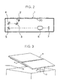
- FIG. 2 is a fragmentary, sectional side elevation showing an image scanning device embodying the present invention;
- FIG. 3 is a fragmentary isometric view of the image scanning device shown in FIG. 2;
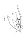
- FIG. 4 is an isometric view demonstrating how a cover plate is mounted to the image scanning device;
- FIGS. 5A through 5C show a procedure for removing a pressing portion included in the cover plate of the illustrative embodiment;
- FIG. 6 is a fragmentary, sectional side elevation showing an alternative embodiment of the present invention;
- FIG. 7 is a fragmentary isometric view showing still another alternative embodiment of the present invention; and
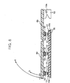
- FIG. 8 is a fragmentary, sectional side elevation showing the embodiment of FIGS. 7A and 7B.
-
- Referring to FIG. 1 of the drawings, an image scanning device embodying the present invention is shown and includes a cover plate. The cover plate includes a
pressing portion 9 generally made up of aframe 8, asheet member 18, anelastic member 11 sandwiched between theframe 8 and thesheet member 18, a plurality offlexible films 17, positioned between theelastic member 11 and theframe 8, and a plurality of planar fasteners (MAGIC TAPE) 12 and 19. As shown in FIG. 2, thesheet member 18 contacts a document 1 laid on aglass platen 20. Theflexible films 17 extend perpendicularly to a direction indicated by an arrow A. Theplanar fasteners flexible films 17 andframe 8. Thefasteners 12 are implemented as loop portions or pile portions while theother fasteners 19 are implemented as hook portions. - As shown in FIG. 2, a
lamp 2 illuminates the document 1 laid on theglass platen 20. The resulting imagewise reflection from the document 1 is incident to a CCD (Charge Coupled Device)array 7 via afirst mirror 3, asecond mirror 4, athird mirror 5, and alens 6. To scan the document 1 in the subscanning direction, while thelamp 2 andmirror 3 move by a distance of "1" to the right, as viewed in FIG. 2, themirrors lens 6 constant. The cover plate is positioned above theglass platen 20 and openable via a hinge or similar connecting member. - More specifically, as shown in FIG. 3, the
pressing portion 9 of the cover plate is removably mounted to theframe 8. Ahinge 10 connects theframe 8 and the body of an image forming apparatus, so that the cover plate is openable away from theglass platen 20, i.e., the document 1. By opening theframe 8 away from theglass platen 20, the operator of the apparatus can lay the document 1 on theglass platen 20 or remove it from theglass platen 20. Theframe 8 is pressed against theglass platen 20 when closed. Theframe 8 andpressing portion 9 may be implemented as a single part or a plurality of parts, as desired. While theframe 8 and pressingmember 9 are shown as being bendable, they may not be bendable. - Referring again to FIG. 1, the
elastic member 11 has a smaller area than thesheet member 18 by a preselected amount. Theloop portions 12 are positioned on theflexible films 17. Thesheet member 18 is formed of PET (polyethylene terephthalate) or similar resin and colored in white in order to prevent the edges of the document 1 from being printed in black on a sheet. Theelastic member 11 is formed of sponge or similar highly elastic material and connected to thesheet member 18 by, e.g., a two-sided adhesive tape. Theelastic films 17 are formed of Mylar or similar material less elastic than theelastic member 11 with respect to the vertical pressure of theframe 8. Theelastic films 17 are separate from each other in the direction perpendicular to the direction A in which theframe 8 is openable. Theelastic films 17 are connected to theelastic member 11 by two-sided adhesive tapes at a preselected distance from each other. - Assume that the
flexible films 17 are implemented as a single film sheet adhered to the entire surface of theelastic member 11. Then, when a force for removing theelastic member 11 from theframe 8 is exerted, as indicated by arrows in FIGS. 5A and 5B, a force tending to return the single film sheet toward theframe 8 acts in the direction opposite to the above direction, obstructing the removal of theelastic member 11. Further, if the mating force acting between theloop portions 12 andhook portions 19 is greater than the elastic force of the single film sheet, then a force exerted to remove the film sheet causes the film sheet to bend. This prevents the cover plate from evenly pressing the document 1 laid on theglass platen 20. - In the illustrative embodiment, the
flexible films 17 are separate from each other in the direction perpendicular to the direction A, as sated earlier. Therefore, theloop portions 12 positioned on theindividual films 17 can be easily, sequentially removed from the side opposite to thehinge 10. Theloop portions 12 positioned on thefilms 17 correspond in position to the hook portion s19 positioned on theframe 8. Eachhook portion 19 may have the same size as eachloop portion 12. Alternatively, one of thehook portion 19 andloop portion 12 may be sized greater than the other in consideration of a possible positional error. Thehook portion 19 andloop portion 12 may, of course, be replaced with each other. - The
loop portions 12 are evenly distributed with respect to thepressing portion 9 in order to scatter a setting force acting between theframe 8 and thepressing portion 9. Therefore, thepressing portion 9 is prevented from locally coming off even when subjected to a shock ascribable to, e.g., the opening or closing of theframe 8. Further, the pressingmember 9 is free from local, intense stresses when removed. In addition, even when thepressing portion 9 is repeated attached and detached for maintenance, it does not damage theelastic member 11 and can be surely attached or detached without any localized adhesive force. - How the
frame 8 andpressing portion 9 are mounted to or dismounted from each other will be described with reference to FIGS. 4 and 5. First, a procedure for mounting thepressing portion 9 will be described. As shown in FIG. 4, the operator lays thepressing portion 9 on theglass platen 20 and then moves thepressing portion 9 in directions A and B to thereby position thepressing portion 9 while guaranteeing spaces between it and scales 13. Subsequently, the operator lowers theframe 8 from the position shown in FIG. 4 toward theglass platen 20 while pressing the front portion (right portion in FIG. 4) of thepressing portion 9 with one hand. After the fasteners of the frame 8 (inclusive of the hook portions 19) at thehinge 10 side have mated with the fasteners of the pressing portion 9 (inclusive of the loop portions 12), the operator releases the front portion of thepressing member 9 and then further lowers theframe portion 8 until all the fasteners fully fasten theframe 8 and pressing portion 9 (closed position). Such a procedure brings about a minimum of dislocation of thepressing portion 9, compared to a case wherein thepressing member 9 is directly fastened to theframe 8. Further, the cover plate can be closed without thepressing member 9 interfering with thescales 13 and allows thepressing portion 9 to press theglass platen 20 without any gap between it and thescale 13. - Particularly, because the
loop portions 12 are adhered to theelastic member 11 via theflexible films 17, the surfaces of thefilms 17 can receive theframe 8. - Assume that the
loop portions 12 are directly adhered to theelastic member 11 as conventional. Then, when theframe 8 is pressed against theloop portions 12, theindividual loop portions 12 are pressed toward theglass platen 20. At this instant, the force of theelastic member 11 tending to return theloop portions 12 toward theframe 8 is too weak to allow theloop portions 12 to surely mate with thehook portions 19. This requires the operator to press theentire frame 8 against thepressing portion 9, then open the cover plate, and then press thepressing portion 9 toward theframe 8 from thesheet 18 side. - A procedure for dismounting the
pressing portion 9 from theframe 8 will be described hereinafter. First, as shown in FIG. 5A, the operator opens the cover plate and then pulls down the front end portion of thepressing portion 9 where thetop loop portions 12 are positioned, as indicated by an arrow. Thepressing portion 9 easily comes off because of theflexible films 17 arranged on theelastic member 11. Thesheet member 18 does not bend because thesheet member 18 is elastic enough to withstand the bending of thepressing portion 9. - Subsequently, the
successive loop portions 12 following thetop loop portions 12 are surely, stably peeled off, so that thepressing portion 9 is surely removed from thepressing portion 9. - It has been customary to directly adhere, e.g., the
loop portions 12 to theelastic member 11. In this configuration, when theloop portions 12 are removed, they are apt to leave theelastic member 11 and remain on thehook portions 19 because the elastic force of theelastic member 11 is weaker than the retaining force of theloop portions 12. Further, when the operator opens the cover plate away from theglass platen 20, thepressing portion 9 is pulled toward theglass platen 20 by adhesion acting between theglass platen 20 and the pressing portion, but theframe 8 moves away from theglass platen 20. As a result, a stress acts on thehook portions 19 and also causes theloop portions 12 to come off and remain on thehook portions 19. - By contrast, in the illustrative embodiment, the
flexible films 17 prevent theloop portions 12 from coming off thefilms 17 in the conditions described above. Moreover, because thefilms 17 are strips extending in the direction perpendicular to the direction A, a tension evenly acts not only on theloop portions 12 but also on theentire films 17, preventing thefilms 17 from coming off theelastic members 11. - As stated above, in the illustrative embodiment, the
pressing portion 9 can evenly contact theglass platen 20. When the cover plate is opened, a minimum of stress acts between the interface between theelastic member 11 and theframe 8 and reduces the impact of theglass platen 20 to thereby facilitate the opening of the cover plate. - An alternative embodiment of the present invention will be described with reference to FIG. 6. As shown, this embodiment differs from the previous embodiment in that it includes a
sheet member 18 having a roughened surface and expected to contact theglass platen 20 or the document 1. Theelastic sheet 11 is positioned between thesheet member 18 and theframe 8. The roughened surface of thesheet member 18forms air gaps 21 between it and theglass platen 20 and allows adhesion between theglass platen 20 and thepressing portion 9 to be suitably reduced, so that the cover platen can be easily opened. - More specifically, the entire surface of the
sheet member 18 expected to contact theglass platen 20 is ground to form theair gaps 21. Air entering theair gaps 21 when the cover plate is opened prevents thesheet member 18 from adhering to theglass platen 20. Theair gaps 21 would form shadows during scanning if excessively large or would obstruct the entry of air in theair gaps 21 if excessively small. Therefore, the above surface of thesheet member 18 should preferably be ground to such a degree that theair gaps 21 would not form shadows during scanning. - In the above configuration, when the cover plate is opened, the
sheet member 18 obviates a force that would cause thepressing portion 9 to adhere to theglass platen 20 and would thereby leave theloop portions 12 on theframe 8. The illustrative therefore allows the cover plate to be easily opened without resorting to theflexible film 17 of the previous embodiment, thereby making the cover plate highly reliable. For example, theloop portions 12 may be directly adhered to theelastic member 11. - The previous embodiment pays attention to the adhesion and elasticity of the
pressing portion 9 andframe 8, so that the cover plate can be easily opened away from theglass platen 20. Theflexible film 17 of the previous embodiment may be applied to the illustrative embodiment also so as to cause the document 1 to surely contact theglass platen 20 during scanning. - Usually, part of the
glass platen 20 corresponding to the end portion of theframe 8 opposite to thehinge 10 does not lie in a scanning range. Therefore, part of thesheet member 18 corresponding to such part of theglass platen 20 may be roughened more than the other part of thesheet member 18, which lies in the scanning range. This reduces a load to act at the beginning of opening of the cover plate for thereby further facilitating the opening of the cover plate. - Reference will be made to FIGS. 7A and 7B for describing another alternative embodiment of the present invention. As shown, this embodiment differs from the embodiment described first in that it includes divided,
elastic members pressing portion 9. Thesheet member 18 expected to contact theglass platen 20 is attached to theelastic members sheet members sheet member 18. The sheet can therefore be evenly, closely pressed against theglass platen 20. - As shown in FIG. 8 as well as in FIGS. 7A and 7B, the
pressing portion 9 for pressing the document is removably mounted to theframe 8 as in the embodiment described first. The cover plate is mounted to the apparatus body via thehinge 10 in such a manner as to be openable away from theglass platen 20. Theframe 8 is made up of a first frame portion 8a and asecond frame portion 8b hinged or otherwise connected to each other. The first frame portion 8a is angularly movable aboutfulcrums 32 relative to thesecond frame portion 8b in directions a and b. By opening theframe 8 away from the glass platen, the operator of the apparatus can lay the document on the glass platen or remove it from the glass platen. - The
fulcrums 32 about which the first frame portion 8a is movable are positioned closer to the fulcrum of the hinge 10 (connected end) than to the intermediate between the opening end of the frame 8 (left end in FIG. 8). In this configuration, when a document cut and pasted or a book document is pressed against the glass platen, thesecond frame portion 8b bends and makes the pressure acting on the document lower at the fulcrum side than at the opening end side. The cover plate can therefore evenly press such a document in accordance with the configuration of the document. - Ribs for reinforcement are formed on the bottom of the
frame 8 that faces the glass platen when the cover plate presses the document. Cubicelastic members 31 formed of, e.g., sponge are adhered to the bottom of theframe 8 in such a manner as to face theloop portions 12 of thepressing portion 9. At least one face of eachelastic member 31 contacts one of the ribs. Thehook portions 19 each are adhered to the face of oneelastic member 31 that faces oneloop portion 12. Thehook portion 19 is equal in area to the above face of the elastic member, but greater in area than theloop portion 12 by a preselected amount. Thehook portions 19 are attached to theframe 8 because thehook portions 19 are more durable than theloop portions 12 and because thehook portions 19 are replaced at the time of maintenance. The area of thehook portions 19 greater than the area of theloop portions 12 is successful to absorb irregularity in parts. The thickness of eachelastic member 31 is selected such that when thehook portion 19 is adhered to themember 31, the hook protrudes above the top of the rib adjoining it. This prevents contact pressure to act when thehook portions 19 andloop portions 12 contact from becoming excessively high. - The sheet member 16 is formed of PET or similar resin and colored white in order to prevent the edges of the document from being printed in black on a sheet. The
elastic members 11a and lib each have a smaller area than thesheet member 18 by a preselected amount and is adhered to thesheet member 18. More specifically, theelastic members sheet member 18 by two-sided adhesive tapes. The position where theelastic members fulcrums 32 about which the frame 8a is movable, so that theelastic members frame portions 8a and 8b (directions a and b, FIG. 8). Assume that the distance between the fulcrum 10a of theframe 8 and the position where theframe 8b is bendable is L2, and that the distance between the above position of theframe 8b and the opening end of theframe 8 is L1. Then, in the illustrative embodiment, the distance or length L1 is selected to be greater than the distance or length L2. - In the above configuration, assume that while the
pressing portion 9 mounted to theframe 8 is resting on a document, the operator lifts the frame 8a in the direction b in order to shift the document. Then, air enters the gap between theglass platen 20 and thesheet member 18 little by little from the opening end side of theframe 8. As a result, adhesion acting between theglass platen 20 and thepressing portion 9 is adequately reduced, facilitating the shift of the document. -
Flexible strips 17 implemented by film sheets are adhered to the other surfaces of theelastic members sheet member 18, i.e., facing theframe 8. Eachstrip 17 has an area smaller than the area of theelastic member strips 17 extend perpendicularly to the direction in which theframe 8 is openable although they may extend in parallel to the above direction. Thestrips 17 may even be so arranged as to adjoin each other in both of the directions perpendicular to and parallel to the opening direction of theframe 8. Thestrips 17 are formed of Mylar or similar material such that their elastic force is weaker than the elastic force of theelastic members frame 8. Thestrips 17 are adhered to theelastic members - The
loop portions 12 are adhered to thestrips 17, and each is smaller in area than eachstrip 17 by a preselected amount and smaller in area than eachhook portion 19 by a preselected amount. Theloop portions 12 so supported by thestrips 17 are protected from peeling or damage when removed from thehook portions 19. If theloop portions 12 are directly adhered to theelastic member 11 softer than theelastic strips 17, then it is likely that theelastic member 11 is damaged when theloop portions 12 are removed from thehook portions 19. - In the illustrative embodiment, the
loop portions 12 that easily wear and deteriorate are attached to thepressing portion 9, which is replaced more frequently than theframe 8. This, coupled with the fact that theloop portions 12 are smaller in area than thehook portions 19, reduces maintenance cost. Theloop portions 12 on eachstrip 17 are positioned closer to the center of thestrip 17 than the four corners of the same. This prevents, when the cover plate is opened in the direction d, FIG. 8, or when the frame 8a is opened in the direction b, FIG. 8, the four sides or theelastic member 11, i.e., the edges of thestrips 17 from being pulled away from themember 11 by adhesion acting between theglass platen 20 and thepressing portion 9. Further, theloop portions 12 are positioned closer to the center of theelastic member 11 than the four corners of the same in order to obviate local, heavy stresses ascribable to the opening and closing of the cover plate. Also, such positions of theloop portions 12 protect theelastic member 11 from damage when the pressing portion is dismounted from theframe 8 for maintenance, while insuring mounting and dismounting free from localized adhesion. - The
pressing portion 9 is mounted to or dismounted from theframe 8 in substantially the same manner as in the embodiment described first. Specifically, to mount thepressing portion 9 to theframe 8, the operator lays thepressing portion 9 on theglass platen 20 and positions thepressing portion 9 while guaranteeing spaces between it and scales 13. Subsequently, the operator lowers theframe 8. After thehook portions 19 have mated with theloop portions 12, the operator further lowers the frame 8a until theframe 8 andpressing portion 9 fully contact each other (closed position) . Such a procedure allows the cover plate to be closed without thepressing member 9 interfering with thescales 13 and allows the edges of thescales 13 andpressing portion 9 to contact each other without any gap. - To dismount the
pressing portion 9 from theframe 8, the operator opens the cover plate and then sequentially removes theloop portions 12 from thehook portions 19 from the top to the bottom. At this instant, theloop portions 12 easily separate from thehook portions 19 because theflexible strips 17 are positioned on the separateelastic members sheet member 18 does not bend because it is elastic enough to withstand the bending of thepressing portion 9. Further, theflexible strips 17 prevent theloop portions 12 from coming off thepressing portion 9 and dropping. Moreover, tension evenly acts on theentire strips 17 when thepressing portion 9 is dismounted, because thestrips 17 extend vertically to the opening and closing direction of theframe 8. This prevents thestrips 17 from coming off theelastic member 11. In addition, theloop portions 17 adhered to thestrips 17 are pressed against thehook portions 19, which protrude above the ribs of theframe 8, so that thepressing portion 9 has the same height. - Again, the
frame 8 andpressing portion 9 may be implemented as a single part or a plurality of parts, as desired. While theframe 8 and pressingmember 9 are shown as being bendable, they may not be bendable. - Assume that the
elastic member 11a has hardness H2 while theelastic member 11b has hardness H1. Then, the hardness H1 may be selected to be greater than the hardness H2 in order to achieve the same advantages as achievable with the previously stated relation of L1 > L2. While any suitable hardness tester may be used to determine such hardness, the illustrative embodiment uses a spring type hardness tester prescribed by SRIS 0101 standards of The Society of Rubber Industry, Japan. - While the illustrative embodiments shown and described have concentrated on an image scanning device, the present invention is similarly applicable to a conventional image forming apparatus of the type including a photoconductive drum, a charger, a writing unit, a developing unit, an image transfer charger, and a separation charger.
- It is to be noted that the flexible member includes the
flexible strips 17 or thesheet member 18 while the mounting/dismounting means includes the planar fasteners (loop portions 12 and hook portions 19). - In summary, it will be seen that the present invention provides a cover plate capable of evenly pressing a document against a glass platen. This is also true when the document is a document cut and pasted or a book document. Further, the cover plate is easy to open away from the glass platen and reduces maintenance cost.
- Various modifications will become possible for those skilled in the art after receiving the teachings of the present disclosure without departing from the scope thereof.
Claims (26)
- A cover plate for pressing a document against a glass platen, said cover plate comprising:a frame connectable to a body of an image forming apparatus or image scanning device in such a manner as to be openable away from the glass platen and divided in a direction perpendicular to an opening/closing direction;a pressing portion for pressing the document laid on the glass platen;at least one mounting/dismounting means for allowing said pressing portion to be selectively mounted to or dismounted from said frame; andan elastic member included in said pressing portion and having a sheet member mounted thereon, said sheet member being divided into a plurality of parts and configured to contact the document.
- The cover plate as claimed in claim 1, wherein said elastic member is divided at a position corresponding to a position where said frame is divided.
- The cover plate as claimed in claim 1 or 2, wherein said elastic member is divided in a direction perpendicular to an opening/closing direction of said frame.
- The cover plate as claimed in claim 1, 2, or 3, wherein a distance between an end of said frame connected to the body and the position where said frame is divided is smaller than a distance between said position and an opening/closing end of said frame.
- The cover plate as claimed in one of claims 1 to 4, wherein one part of said frame between an end of said frame connected to the body and the position where said frame is divided has hardness lower than the other part between said position and an opening/closing end of said frame.
- The cover plate as claimed in one of claims 1 to 5, wherein a surface of said sheet member to contact the glass platen is roughened.
- The cover plate as claimed in one of claims 1 to 6, wherein surface roughness of said sheet member differs from a portion adjoining an end of said frame connected to the body to a portion adjoining an opening/closing end of said frame.
- A cover plate, in particular in accordance with one of claims 1 to 7 for pressing a document against a glass platen, said cover plate comprising:wherein said pressing portion comprises a sheet member configured to contact the document, an elastic member intervening between said sheet member and said frame, and a plurality of flexible members intervening between said elastic member and said frame; anda frame connectable to a body of an image forming apparatus in such a manner as to be openable away from the glass platen and divided in a direction perpendicular to an opening/closing direction;a pressing portion for pressing the document laid on the glass platen; anda plurality of mounting/dismounting means for allowing said pressing portion to be selectively mounted to or dismounted from said frame;said plurality of mounting/dismounting means each are attached to a respective flexible member.
- The cover plate as claimed in claim 8, wherein said flexible member is divided at a position corresponding to a position where said frame is divided.
- The cover plate as claimed in claim 9 or 10, wherein said flexible member is divided in a direction perpendicular to an opening/closing direction of said frame.
- The cover plate as claimed in claim 8, 9, or 10 wherein a surface of said sheet member to contact the glass platen is roughened.
- The cover plate as claimed in claim 11, wherein surface roughness of said sheet member differs from a portion adjoining a side where said frame is connected to the body to a portion adjoining an opening/closing end of said frame.
- A cover plate in paticular in accordance with one of claims 1 to 12 for pressing a document against a glass platen, said cover plate comprising:a frame connectable to a body of an image forming apparatus in such a manner as to be openable away from the glass platen and divided in a direction perpendicular to an opening/closing direction;a pressing portion for pressing the document laid on the glass platen; anda plurality of mounting/dismounting means for allowing said pressing portion to be selectively mounted to or dismounted from said frame, said plurality of mounting/dismounting means being arranged at at least six positions on said pressing portion other than four corners.
- The cover plate as claimed in claiml 13, wherein said mounting/dismounting means are arranged at a center portion other than the four corners.
- The cover plate as claimed in claim 13 or 14, wherein said mounting/dismounting means comprise planar fasteners made up of hook portions adhered to said frame and loop portions adhered to said pressing portion, and each of said hook portions and each of said loop portions have a same area as each other.
- The cover plate as claimed in one of claims 13 to 15, wherein said pressing portion comprises:a sheet member configured to contact the document;a plurality of elastic members intervening between said sheet member and said frame and divided in a direction perpendicular to an opening/closing direction of said frame at a position corresponding to a position where said frame is divided; anda plurality of flexible members intervening between said plurality of elastic members and said frame and divided in the direction perpendicular to the opening/closing direction of said frame at the position where said frame is divided, said loop portions each being attached to a respective flexible member.
- The cover plate as claimed in claim 16, wherein said loop portions each have a smaller area than each of said flexible members, and said loop portions are arranged at a center portion other than four corners of the flexible member.
- The cover plate as claimed in one of claims 15 to 17, wherein a plurality of elastic members each having a respective hook portion thereon are mounted on a bottom of said frame facing said pressing portion.
- The cover plate as claimed in claim 18, wherein said elastic members have such a height that said hook portions protrude above ends of ribs, which are mounted on said frame.
- The cover plate as claimed in one of claims 13 to 19, wherein a surface of said sheet member to contact the glass platen is roughened.
- The cover plate as claimed in claim 20, wherein surface roughness of said sheet member differs from a portion adjoining an end of said frame connected to the body and an opening/closing end of said frame.
- An image scanning device or image forming apparater including a cover plate as claimed in are of claims 1 to 21, wherein the frame is connected to the body.
- An image scanning device or image forming apparatus in particular in accordance with claim 22 comprising:wherein said mounting/dismounting means comprises planar fasteners made up of hook portions mounted on hook support members and loop portions mounted on loop support members.reading means comprising a light-sensitive device array extending in a main scanning direction;a light source for illuminating a document;optical means for focusing a reflection from the document on said reading means;drive means for causing the document and said reading means to move relative to each other in a subscanning direction; anddocument pressing means openable away from a casing and comprising a hinge, a frame, a pressing portion for pressing the document, and mounting/dismounting means for allowing said pressing portion to be selectively mounted to or dismounted from said frame;
- The device as claimed in claim 23, wherein said hook support members and said loop support members are mounted on said frame and said pressing portion, respectively.
- The device as claimed in claim 23 or 24, wherein said hook support members are mounted on said frame via an elastic member.
- The device as claimed in claim 23, 24, or 25, wherein said hook support members and said loop support members each have a particular area.
Applications Claiming Priority (6)
| Application Number | Priority Date | Filing Date | Title |
|---|---|---|---|
| JP2001157179 | 2001-05-25 | ||
| JP2001157179A JP2002350997A (en) | 2001-05-25 | 2001-05-25 | Image reading device |
| JP2001179750 | 2001-06-14 | ||
| JP2001179750 | 2001-06-14 | ||
| JP2002118264 | 2002-04-19 | ||
| JP2002118264A JP4108358B2 (en) | 2001-06-14 | 2002-04-19 | Document pressure plate, image reading apparatus, and image forming apparatus |
Publications (2)
| Publication Number | Publication Date |
|---|---|
| EP1260876A1 true EP1260876A1 (en) | 2002-11-27 |
| EP1260876B1 EP1260876B1 (en) | 2013-05-22 |
Family
ID=27346785
Family Applications (1)
| Application Number | Title | Priority Date | Filing Date |
|---|---|---|---|
| EP02011558.0A Expired - Lifetime EP1260876B1 (en) | 2001-05-25 | 2002-05-24 | A platen cover, image scanning device and image forming apparatus with the cover |
Country Status (2)
| Country | Link |
|---|---|
| US (1) | US6697600B2 (en) |
| EP (1) | EP1260876B1 (en) |
Cited By (2)
| Publication number | Priority date | Publication date | Assignee | Title |
|---|---|---|---|---|
| GB2400516A (en) * | 2003-03-26 | 2004-10-13 | Hewlett Packard Development Co | Apparatus and method for limiting media movement on an imaging apparatus |
| KR100753189B1 (en) * | 2004-01-12 | 2007-08-30 | 삼성전자주식회사 | Image reading apparatus having improved cover apparatus |
Families Citing this family (19)
| Publication number | Priority date | Publication date | Assignee | Title |
|---|---|---|---|---|
| US8450302B2 (en) * | 2002-08-02 | 2013-05-28 | Ab Science | 2-(3-aminoaryl) amino-4-aryl-thiazoles and their use as c-kit inhibitors |
| DE60316810T2 (en) | 2002-08-02 | 2008-07-17 | Ab Science | 2- (3-AMINOARYL) AMINO-4-ARYL-THIAZOLE AND THEIR USE AS C-KIT INHIBITORS |
| JP2006121658A (en) * | 2004-09-27 | 2006-05-11 | Brother Ind Ltd | Multifunction printer, print system, and image forming apparatus |
| JP4331668B2 (en) * | 2004-11-11 | 2009-09-16 | シャープ株式会社 | Document reader |
| US7453055B2 (en) * | 2005-04-28 | 2008-11-18 | Brother Kogyo Kabushiki Kaisha | Image reading apparatus |
| TWI278223B (en) * | 2005-09-20 | 2007-04-01 | Benq Corp | Scanner |
| JP4345831B2 (en) * | 2007-03-12 | 2009-10-14 | ブラザー工業株式会社 | Image reading device |
| JP5130166B2 (en) * | 2008-09-10 | 2013-01-30 | 京セラドキュメントソリューションズ株式会社 | Document holding device and image forming apparatus equipped with the same |
| US8199374B2 (en) * | 2009-05-08 | 2012-06-12 | Hewlett-Packard Development Company, L.P. | Apparatus and method for retaining a document during imaging |
| JP5721402B2 (en) * | 2010-11-17 | 2015-05-20 | キヤノン株式会社 | Image reading apparatus and image forming apparatus |
| JP5921522B2 (en) * | 2013-11-21 | 2016-05-24 | 京セラドキュメントソリューションズ株式会社 | Image reading apparatus and image forming apparatus |
| US10855861B2 (en) | 2016-09-09 | 2020-12-01 | Hewlett-Packard Development Company, L.P. | Reflective sheet coupling |
| TWM546063U (en) * | 2017-04-20 | 2017-07-21 | Kinpo Elect Inc | Scanner gland |
| JP7196644B2 (en) | 2019-01-30 | 2022-12-27 | 株式会社リコー | TILT DETECTION DEVICE, READING DEVICE, IMAGE PROCESSING DEVICE, AND TILT DETECTION METHOD |
| JP7131415B2 (en) | 2019-01-31 | 2022-09-06 | 株式会社リコー | TILT DETECTION DEVICE, READING DEVICE, IMAGE PROCESSING DEVICE, AND TILT DETECTION METHOD |
| US11463601B2 (en) | 2019-07-12 | 2022-10-04 | Seiko Epson Corporation | Image reading apparatus with a document feeder with a pressing layer |
| DE202021103737U1 (en) | 2021-07-12 | 2021-07-28 | ColorDigital GmbH | Device attachment for a flatbed scanner |
| JP2023101098A (en) * | 2022-01-07 | 2023-07-20 | セイコーエプソン株式会社 | Image reader |
| JP2025067392A (en) * | 2023-10-13 | 2025-04-24 | セイコーエプソン株式会社 | Image reading device |
Citations (4)
| Publication number | Priority date | Publication date | Assignee | Title |
|---|---|---|---|---|
| US1144014A (en) | 1914-12-14 | 1915-06-22 | Ernest Williams | Printing-frame. |
| US3685905A (en) | 1971-04-22 | 1972-08-22 | Xerox Corp | Combined document feed and book copying apparatus |
| US4157222A (en) | 1977-04-29 | 1979-06-05 | Minolta Camera Kabushiki Kaisha | Document hold-down cover for use in copying apparatus |
| JPH10153889A (en) * | 1996-11-22 | 1998-06-09 | Sharp Corp | Document feeder |
Family Cites Families (7)
| Publication number | Priority date | Publication date | Assignee | Title |
|---|---|---|---|---|
| JPH0422346A (en) | 1990-05-17 | 1992-01-27 | Toshiba Corp | Body motion correcting system for x-ray ct |
| JPH06313930A (en) | 1993-04-28 | 1994-11-08 | Copyer Co Ltd | Original holding device for image forming device |
| JPH0795368A (en) | 1993-09-24 | 1995-04-07 | Canon Inc | Document reader and copier |
| JPH07191419A (en) | 1993-12-27 | 1995-07-28 | Copyer Co Ltd | Original holding device for image forming device |
| JPH08201935A (en) | 1995-01-25 | 1996-08-09 | Ricoh Co Ltd | Image reader |
| US5574542A (en) * | 1996-02-14 | 1996-11-12 | Agfa Division, Bayer Corporation | Scanner cover |
| JP3608646B2 (en) | 1997-07-18 | 2005-01-12 | 株式会社リコー | Image forming apparatus and intermediate transfer unit used in the apparatus |
-
2002
- 2002-05-24 EP EP02011558.0A patent/EP1260876B1/en not_active Expired - Lifetime
- 2002-05-28 US US10/155,090 patent/US6697600B2/en not_active Expired - Lifetime
Patent Citations (4)
| Publication number | Priority date | Publication date | Assignee | Title |
|---|---|---|---|---|
| US1144014A (en) | 1914-12-14 | 1915-06-22 | Ernest Williams | Printing-frame. |
| US3685905A (en) | 1971-04-22 | 1972-08-22 | Xerox Corp | Combined document feed and book copying apparatus |
| US4157222A (en) | 1977-04-29 | 1979-06-05 | Minolta Camera Kabushiki Kaisha | Document hold-down cover for use in copying apparatus |
| JPH10153889A (en) * | 1996-11-22 | 1998-06-09 | Sharp Corp | Document feeder |
Non-Patent Citations (1)
| Title |
|---|
| PATENT ABSTRACTS OF JAPAN vol. 1998, no. 11 30 September 1998 (1998-09-30) * |
Cited By (4)
| Publication number | Priority date | Publication date | Assignee | Title |
|---|---|---|---|---|
| GB2400516A (en) * | 2003-03-26 | 2004-10-13 | Hewlett Packard Development Co | Apparatus and method for limiting media movement on an imaging apparatus |
| US6990311B2 (en) | 2003-03-26 | 2006-01-24 | Hewlett-Packard Development Company, L.P. | Apparatus and method for limiting media movement on an imaging apparatus |
| KR100753189B1 (en) * | 2004-01-12 | 2007-08-30 | 삼성전자주식회사 | Image reading apparatus having improved cover apparatus |
| US7676189B2 (en) | 2004-01-12 | 2010-03-09 | Samsung Electronics Co., Ltd. | Image reading apparatus having improved cover device |
Also Published As
| Publication number | Publication date |
|---|---|
| US6697600B2 (en) | 2004-02-24 |
| US20020191996A1 (en) | 2002-12-19 |
| EP1260876B1 (en) | 2013-05-22 |
Similar Documents
| Publication | Publication Date | Title |
|---|---|---|
| US6697600B2 (en) | Cover plate, image scanning device and image forming apparatus | |
| US6968138B2 (en) | Developer seal member and developing apparatus using the seal | |
| CA2147938A1 (en) | Image Forming Apparatus | |
| US7616353B2 (en) | Image reading unit and image forming apparatus comprising the same | |
| CN102377904B (en) | Image reader and image forming apparatus | |
| JP2003131159A (en) | Image forming device | |
| JP4108358B2 (en) | Document pressure plate, image reading apparatus, and image forming apparatus | |
| US20220394148A1 (en) | Image reading apparatus | |
| JP2024043483A (en) | Image reading device and image forming device | |
| CN112180706B (en) | Image forming apparatus | |
| JP2001022010A (en) | Document holding device and document reading device | |
| US12256048B2 (en) | Image reading apparatus and image forming apparatus comprising a reading portion, the reading portion includes an image sensor, casing, transparent member and a shield member between the transparent member and casing, and electrically grounded | |
| US7738144B2 (en) | Document reading device and image forming apparatus using the same | |
| JP3612230B2 (en) | Image scanning device | |
| JP2000314992A (en) | Automatic document feeder | |
| JP3816411B2 (en) | Image reading device | |
| JP2012054458A (en) | Retainer (fixture) for holding flexible flat cable, and image forming apparatus using the same | |
| JP2002131990A (en) | Image reading device | |
| EP0480418B1 (en) | Image reading device | |
| JP4108377B2 (en) | Document pressure plate and image reading apparatus | |
| JP3594773B2 (en) | Image input device | |
| JPH08289099A (en) | Image reader | |
| JP3558888B2 (en) | Image reading device | |
| JPH0545572A (en) | Mirror holding device for image forming device | |
| JPH04217282A (en) | Image forming device |
Legal Events
| Date | Code | Title | Description |
|---|---|---|---|
| PUAI | Public reference made under article 153(3) epc to a published international application that has entered the european phase |
Free format text: ORIGINAL CODE: 0009012 |
|
| 17P | Request for examination filed |
Effective date: 20020524 |
|
| AK | Designated contracting states |
Kind code of ref document: A1 Designated state(s): AT BE CH CY DE DK ES FI FR GB GR IE IT LI LU MC NL PT SE TR |
|
| AX | Request for extension of the european patent |
Free format text: AL;LT;LV;MK;RO;SI |
|
| AKX | Designation fees paid |
Designated state(s): DE FR GB |
|
| 17Q | First examination report despatched |
Effective date: 20090522 |
|
| R17C | First examination report despatched (corrected) |
Effective date: 20090525 |
|
| GRAP | Despatch of communication of intention to grant a patent |
Free format text: ORIGINAL CODE: EPIDOSNIGR1 |
|
| GRAS | Grant fee paid |
Free format text: ORIGINAL CODE: EPIDOSNIGR3 |
|
| GRAA | (expected) grant |
Free format text: ORIGINAL CODE: 0009210 |
|
| AK | Designated contracting states |
Kind code of ref document: B1 Designated state(s): DE FR GB |
|
| REG | Reference to a national code |
Ref country code: GB Ref legal event code: FG4D |
|
| REG | Reference to a national code |
Ref country code: DE Ref legal event code: R096 Ref document number: 60244980 Country of ref document: DE Effective date: 20130718 |
|
| PLBE | No opposition filed within time limit |
Free format text: ORIGINAL CODE: 0009261 |
|
| STAA | Information on the status of an ep patent application or granted ep patent |
Free format text: STATUS: NO OPPOSITION FILED WITHIN TIME LIMIT |
|
| 26N | No opposition filed |
Effective date: 20140225 |
|
| REG | Reference to a national code |
Ref country code: DE Ref legal event code: R097 Ref document number: 60244980 Country of ref document: DE Effective date: 20140225 |
|
| REG | Reference to a national code |
Ref country code: FR Ref legal event code: PLFP Year of fee payment: 15 |
|
| REG | Reference to a national code |
Ref country code: FR Ref legal event code: PLFP Year of fee payment: 16 |
|
| PGFP | Annual fee paid to national office [announced via postgrant information from national office to epo] |
Ref country code: DE Payment date: 20170523 Year of fee payment: 16 Ref country code: GB Payment date: 20170519 Year of fee payment: 16 Ref country code: FR Payment date: 20170523 Year of fee payment: 16 |
|
| REG | Reference to a national code |
Ref country code: DE Ref legal event code: R119 Ref document number: 60244980 Country of ref document: DE |
|
| GBPC | Gb: european patent ceased through non-payment of renewal fee |
Effective date: 20180524 |
|
| PG25 | Lapsed in a contracting state [announced via postgrant information from national office to epo] |
Ref country code: GB Free format text: LAPSE BECAUSE OF NON-PAYMENT OF DUE FEES Effective date: 20180524 Ref country code: FR Free format text: LAPSE BECAUSE OF NON-PAYMENT OF DUE FEES Effective date: 20180531 Ref country code: DE Free format text: LAPSE BECAUSE OF NON-PAYMENT OF DUE FEES Effective date: 20181201 |