EP1260760A2 - Controlled-luminance lighting device - Google Patents
Controlled-luminance lighting device Download PDFInfo
- Publication number
- EP1260760A2 EP1260760A2 EP02010656A EP02010656A EP1260760A2 EP 1260760 A2 EP1260760 A2 EP 1260760A2 EP 02010656 A EP02010656 A EP 02010656A EP 02010656 A EP02010656 A EP 02010656A EP 1260760 A2 EP1260760 A2 EP 1260760A2
- Authority
- EP
- European Patent Office
- Prior art keywords
- another
- elements
- light source
- reflector
- fins
- Prior art date
- Legal status (The legal status is an assumption and is not a legal conclusion. Google has not performed a legal analysis and makes no representation as to the accuracy of the status listed.)
- Granted
Links
Images

Classifications
-
- F—MECHANICAL ENGINEERING; LIGHTING; HEATING; WEAPONS; BLASTING
- F21—LIGHTING
- F21V—FUNCTIONAL FEATURES OR DETAILS OF LIGHTING DEVICES OR SYSTEMS THEREOF; STRUCTURAL COMBINATIONS OF LIGHTING DEVICES WITH OTHER ARTICLES, NOT OTHERWISE PROVIDED FOR
- F21V7/00—Reflectors for light sources
- F21V7/005—Reflectors for light sources with an elongated shape to cooperate with linear light sources
-
- F—MECHANICAL ENGINEERING; LIGHTING; HEATING; WEAPONS; BLASTING
- F21—LIGHTING
- F21S—NON-PORTABLE LIGHTING DEVICES; SYSTEMS THEREOF; VEHICLE LIGHTING DEVICES SPECIALLY ADAPTED FOR VEHICLE EXTERIORS
- F21S2/00—Systems of lighting devices, not provided for in main groups F21S4/00 - F21S10/00 or F21S19/00, e.g. of modular construction
- F21S2/005—Systems of lighting devices, not provided for in main groups F21S4/00 - F21S10/00 or F21S19/00, e.g. of modular construction of modular construction
-
- F—MECHANICAL ENGINEERING; LIGHTING; HEATING; WEAPONS; BLASTING
- F21—LIGHTING
- F21S—NON-PORTABLE LIGHTING DEVICES; SYSTEMS THEREOF; VEHICLE LIGHTING DEVICES SPECIALLY ADAPTED FOR VEHICLE EXTERIORS
- F21S8/00—Lighting devices intended for fixed installation
- F21S8/02—Lighting devices intended for fixed installation of recess-mounted type, e.g. downlighters
-
- F—MECHANICAL ENGINEERING; LIGHTING; HEATING; WEAPONS; BLASTING
- F21—LIGHTING
- F21S—NON-PORTABLE LIGHTING DEVICES; SYSTEMS THEREOF; VEHICLE LIGHTING DEVICES SPECIALLY ADAPTED FOR VEHICLE EXTERIORS
- F21S8/00—Lighting devices intended for fixed installation
- F21S8/04—Lighting devices intended for fixed installation intended only for mounting on a ceiling or the like overhead structures
- F21S8/06—Lighting devices intended for fixed installation intended only for mounting on a ceiling or the like overhead structures by suspension
-
- F—MECHANICAL ENGINEERING; LIGHTING; HEATING; WEAPONS; BLASTING
- F21—LIGHTING
- F21V—FUNCTIONAL FEATURES OR DETAILS OF LIGHTING DEVICES OR SYSTEMS THEREOF; STRUCTURAL COMBINATIONS OF LIGHTING DEVICES WITH OTHER ARTICLES, NOT OTHERWISE PROVIDED FOR
- F21V11/00—Screens not covered by groups F21V1/00, F21V3/00, F21V7/00 or F21V9/00
- F21V11/02—Screens not covered by groups F21V1/00, F21V3/00, F21V7/00 or F21V9/00 using parallel laminae or strips, e.g. of Venetian-blind type
-
- F—MECHANICAL ENGINEERING; LIGHTING; HEATING; WEAPONS; BLASTING
- F21—LIGHTING
- F21V—FUNCTIONAL FEATURES OR DETAILS OF LIGHTING DEVICES OR SYSTEMS THEREOF; STRUCTURAL COMBINATIONS OF LIGHTING DEVICES WITH OTHER ARTICLES, NOT OTHERWISE PROVIDED FOR
- F21V13/00—Producing particular characteristics or distribution of the light emitted by means of a combination of elements specified in two or more of main groups F21V1/00 - F21V11/00
- F21V13/02—Combinations of only two kinds of elements
- F21V13/10—Combinations of only two kinds of elements the elements being reflectors and screens
-
- F—MECHANICAL ENGINEERING; LIGHTING; HEATING; WEAPONS; BLASTING
- F21—LIGHTING
- F21Y—INDEXING SCHEME ASSOCIATED WITH SUBCLASSES F21K, F21L, F21S and F21V, RELATING TO THE FORM OR THE KIND OF THE LIGHT SOURCES OR OF THE COLOUR OF THE LIGHT EMITTED
- F21Y2103/00—Elongate light sources, e.g. fluorescent tubes
Definitions
- the present invention relates to lighting devices, for example ones used in residential, commercial and industrial environments, of the kind comprising at least one fluorescent light source of a linear type, which extends longitudinally between a reflector that is formed by an elongated body having a curved surface, and a set of transverse fins, which are set at a distance apart from one another and which define a grill for directional control of the light emitted by the light source.
- Light sources of the above sort consist, in practice, of a reflecting optical system designed to control the direction of the outcoming light, guaranteeing limits of luminance below dazzling.
- transverse fins are generally made up of simple extruded metallic elements having a parabolic profile in the direction perpendicular to the direction of extrusion
- angular control of the outcoming light is effective only in the planes that are, respectively, perpendicular and parallel to the axis of the lamp. In the remaining directions, this control is normally ineffective, and, in any case, insufficient.
- the purpose of the present invention is precisely to solve the above problem and to provide a lighting device of the type defined above, which is designed to enable control of the luminance in all directions.
- the above purpose is achieved basically thanks to the fact that, in a lighting device of the type defined at the beginning of this description, the reflector defines, together with said transverse fins, a plurality of elements set alongside one another having a generally parabolic shape.
- Each of said elements set alongside one another conveniently has a bottom wall formed with a cusp in a position corresponding to the light source.
- the reflector is made up of two separable units, one of which includes said fins and the other includes the bottom walls of said elements set alongside one another.
- the lighting device illustrated by way of example in the drawings is made up of a reflecting-optical system designed to control the outcoming light beam angularly in its longitudinal plane and in its transverse plane, as well as in all the intermediate planes comprised between the above planes, so guaranteeing limits of luminance below dazzling.
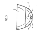
- the lighting device comprises a reflector, designated as a whole by 1, formed by an elongated body having its internal surface generally curved.
- Said elongated body 1 is, in effect, defined by a set of tray-like elements 2 having a parabolic shape, which are separated from one another by transverse fins 3 set apart from each other, the said fins having a shaped profile.
- each element 2 is formed with a cusp 4, above which there extends a fluorescent light source 5 of a linear type, the length of which substantially corresponds to the length of the elongated body 1.
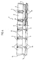
- the transverse fins 3, which define a grid for directional control of the light emitted by the source 5, have a three-dimensional profile with curved sides and are conveniently hollow so as to define compartments 6 between each pair of adjacent elements 2.
- the elongated body 1 can advantageously be made up of two longitudinal portions, which can be separated from one another in order to facilitate positioning of the light source 5 and which are then assembled together using any suitable system.
- the above longitudinal portions include a lower portion 1a, forming the lower portions of the elements 2 with the corresponding bottom walls 2a and cusps 4, and an upper portion 1b, which includes the upper areas of the elements 2 and the transverse fins 3.
- the lighting device enables angular control of the light beam generated by the source 5, not only in the plane perpendicular to the axis of the source 5 and in the plane parallel to the axis of the source 5, but also in all the planes that are intermediate between the above planes.
- the device according to the invention can be set into a wall or ceiling (obviously, in a position upside down with respect to the one illustrated in the drawings) or it can be set suspended.
- the device may conveniently be formed with openings or slits in positions corresponding to the bottom walls 2a of the elements 2.
- the device described above is modular, in the sense that it can be made up of similar devices in order to obtain the widest possible range of configurations.
Landscapes
- Engineering & Computer Science (AREA)
- General Engineering & Computer Science (AREA)
- Non-Portable Lighting Devices Or Systems Thereof (AREA)
- Light Sources And Details Of Projection-Printing Devices (AREA)
- Manufacture, Treatment Of Glass Fibers (AREA)
- Road Signs Or Road Markings (AREA)
- Endoscopes (AREA)
- Circuit Arrangement For Electric Light Sources In General (AREA)
Abstract
Description
- Figure 1 is a schematic perspective plan view from underneath of a controlled-luminance lighting device according to the invention;
- Figure 2 is a view similar to that of Figure 1, in which, however, the light source has been suppressed in order to highlight the structure of the device better;
- Figure 3 is a cross-sectional view at an enlarged scale taken along the line III-III of Figure 1; and
- Figure 4 is a side elevation and partially sectioned longitudinal view of Figure 1.
Claims (7)
- A controlled-luminance lighting device, comprising at least one fluorescent light source of a linear type (5), which extends longitudinally between a reflector (1) that is formed by an elongated body having a curved surface, and a set of transverse fins (3), which are set at a distance apart from one another and which define a grill for directional control of the light emitted by said light source (5), characterized in that the reflector (1) defines, together with said transverse fins (3), a plurality of elements (2), set alongside one another, of a generally parabolic shape.
- The device according to Claim 1, characterized in that said fins (3) have a three-dimensional profile.
- The device according to Claim 2, characterized in that said fins (3) are hollow.
- The device according to any one of the preceding claims, characterized in that each of said elements (2) set alongside one another has a bottom wall (2a) formed with a cusp (4), in a position corresponding to the light source (5).
- The device according to Claim 4, characterized in that said reflector (1) is made up of two separable units (la, 1b) one of which includes the bottom walls (2a) of said elements (2) set alongside one another, and the other of which includes said transverse fins (3).
- The device according to Claim 4 or Claim 5, characterized in that the bottom wall (2a) of said elements (2) set alongside one another is formed with openings.
- The device according to one or more of the preceding claims, characterized in that it is usable set in or suspended.
Applications Claiming Priority (2)
| Application Number | Priority Date | Filing Date | Title |
|---|---|---|---|
| ITTO20010460 | 2001-05-18 | ||
| IT2001TO000460A ITTO20010460A1 (en) | 2001-05-18 | 2001-05-18 | CONTROLLED LUMINANCE LIGHTING DEVICE. |
Publications (3)
| Publication Number | Publication Date |
|---|---|
| EP1260760A2 true EP1260760A2 (en) | 2002-11-27 |
| EP1260760A3 EP1260760A3 (en) | 2005-10-19 |
| EP1260760B1 EP1260760B1 (en) | 2007-09-12 |
Family
ID=11458861
Family Applications (1)
| Application Number | Title | Priority Date | Filing Date |
|---|---|---|---|
| EP02010656A Expired - Lifetime EP1260760B1 (en) | 2001-05-18 | 2002-05-13 | Controlled-luminance lighting device |
Country Status (5)
| Country | Link |
|---|---|
| US (1) | US6705746B2 (en) |
| EP (1) | EP1260760B1 (en) |
| AT (1) | ATE373201T1 (en) |
| DE (1) | DE60222321T2 (en) |
| IT (1) | ITTO20010460A1 (en) |
Cited By (5)
| Publication number | Priority date | Publication date | Assignee | Title |
|---|---|---|---|---|
| FR2862124A1 (en) * | 2003-11-06 | 2005-05-13 | Sli France | Light fixture, has blades with concave and convex surfaces having transversal section in horizontal plane, where section divides light flow and reduces vertical plane illumination along longitudinal axis of linear fluorescent lamp |
| DE102004005917A1 (en) * | 2004-02-06 | 2005-08-25 | Zumtobel Staff Gmbh | Reflector arrangement for a luminaire with a plurality of reflector chambers arranged in series |
| WO2005090854A1 (en) * | 2004-03-12 | 2005-09-29 | Honeywell International Inc. | Luminaires for artificial lighting |
| US7195374B2 (en) | 2004-03-12 | 2007-03-27 | Honeywell International, Inc. | Luminaires for artificial lighting |
| EP3366993A1 (en) * | 2017-02-28 | 2018-08-29 | Zumtobel Lighting GmbH | Lamp with reflector element and reflector element |
Families Citing this family (10)
| Publication number | Priority date | Publication date | Assignee | Title |
|---|---|---|---|---|
| US6789914B1 (en) | 2003-05-29 | 2004-09-14 | Hubbell Incorporated | Luminaire providing direct and indirect lighting |
| US20060176701A1 (en) * | 2005-02-04 | 2006-08-10 | Shemit Sylvan R | Reflector-baffle for luminaires |
| USD615696S1 (en) * | 2008-02-04 | 2010-05-11 | Electronic Controls Company | Reflector |
| USD667987S1 (en) * | 2011-07-20 | 2012-09-25 | Ningbo Yinzhou Self Photoelectron Technology Co., Ltd. | LED lighthead |
| USD668378S1 (en) * | 2011-08-22 | 2012-10-02 | Ningbo Yinzhou Self Photoelectron Technology Co., Ltd. | LED reflector |
| USD702872S1 (en) * | 2011-09-16 | 2014-04-15 | Ningbo Yinzhou Self Photoelectron Technology Co., Ltd. | Reflex plate |
| US9616811B2 (en) * | 2012-07-10 | 2017-04-11 | Emergency Technology, Inc. | Emergency vehicle light fixture with reflective surface having alternating linear and revolved parabolic segments |
| USD718487S1 (en) * | 2013-08-08 | 2014-11-25 | Emergency Technology, Inc. | Reflector |
| USD707384S1 (en) * | 2013-08-09 | 2014-06-17 | Soundoff Signal, Inc. | Reflector |
| DE102014115823A1 (en) * | 2014-10-30 | 2016-05-04 | Itz Innovations- Und Technologiezentrum Gmbh | LED glare grid with fins |
Family Cites Families (10)
| Publication number | Priority date | Publication date | Assignee | Title |
|---|---|---|---|---|
| FR2554549B1 (en) * | 1983-11-03 | 1988-03-11 | Sabir | ANTI-GLARE DEVICE FOR LUMINAIRES WITH LINEAR SOURCES |
| US4729075A (en) * | 1985-05-29 | 1988-03-01 | Brass John R | Constant zone reflector for luminaires and method |
| US4751626A (en) * | 1987-05-28 | 1988-06-14 | Columbia Lighting, Inc. | Reflector system for a luminaire |
| JPH04133205A (en) | 1990-09-25 | 1992-05-07 | Toshiba Lighting & Technol Corp | Lighting fixture |
| DE9017372U1 (en) * | 1990-12-22 | 1991-04-04 | Großkinsky, Wilfried, 5000 Köln | Luminaire, especially ceiling or wall light |
| SE469804B (en) * | 1991-12-09 | 1993-09-13 | Fagerhults Ab | Reflector for an electric radiation luminaire and an electric radiation luminaire provided with such a reflector |
| ATE147493T1 (en) * | 1993-11-08 | 1997-01-15 | Branka Agabekov | LIGHT BAR |
| FR2734044B1 (en) * | 1995-05-11 | 1997-08-01 | Vial Henri Noel | SCREEN GRID FOR FLUORESCENT LIGHTING |
| EP1113219B1 (en) * | 1999-12-27 | 2008-01-02 | Ludwig Leuchten KG | Lamp |
| US6231212B1 (en) * | 1999-12-28 | 2001-05-15 | Aced Designs, Inc. | Fluorescent lamp baffle |
-
2001
- 2001-05-18 IT IT2001TO000460A patent/ITTO20010460A1/en unknown
-
2002
- 2002-05-13 EP EP02010656A patent/EP1260760B1/en not_active Expired - Lifetime
- 2002-05-13 AT AT02010656T patent/ATE373201T1/en not_active IP Right Cessation
- 2002-05-13 DE DE60222321T patent/DE60222321T2/en not_active Expired - Lifetime
- 2002-05-16 US US10/145,886 patent/US6705746B2/en not_active Expired - Lifetime
Cited By (5)
| Publication number | Priority date | Publication date | Assignee | Title |
|---|---|---|---|---|
| FR2862124A1 (en) * | 2003-11-06 | 2005-05-13 | Sli France | Light fixture, has blades with concave and convex surfaces having transversal section in horizontal plane, where section divides light flow and reduces vertical plane illumination along longitudinal axis of linear fluorescent lamp |
| DE102004005917A1 (en) * | 2004-02-06 | 2005-08-25 | Zumtobel Staff Gmbh | Reflector arrangement for a luminaire with a plurality of reflector chambers arranged in series |
| WO2005090854A1 (en) * | 2004-03-12 | 2005-09-29 | Honeywell International Inc. | Luminaires for artificial lighting |
| US7195374B2 (en) | 2004-03-12 | 2007-03-27 | Honeywell International, Inc. | Luminaires for artificial lighting |
| EP3366993A1 (en) * | 2017-02-28 | 2018-08-29 | Zumtobel Lighting GmbH | Lamp with reflector element and reflector element |
Also Published As
| Publication number | Publication date |
|---|---|
| US6705746B2 (en) | 2004-03-16 |
| ITTO20010460A0 (en) | 2001-05-18 |
| ITTO20010460A1 (en) | 2002-11-18 |
| ATE373201T1 (en) | 2007-09-15 |
| EP1260760B1 (en) | 2007-09-12 |
| EP1260760A3 (en) | 2005-10-19 |
| DE60222321T2 (en) | 2007-12-27 |
| US20020172044A1 (en) | 2002-11-21 |
| DE60222321D1 (en) | 2007-10-25 |
Similar Documents
| Publication | Publication Date | Title |
|---|---|---|
| EP1260760B1 (en) | Controlled-luminance lighting device | |
| US6641282B2 (en) | Controlled-luminance lighting device | |
| KR101207324B1 (en) | A luminaire comprising leds | |
| US3532876A (en) | Light fitting having at least one tubular lamp and a transparent covering of synthetic resin glass with a prismatic surface | |
| WO2014001484A1 (en) | Lens for led illumination | |
| ES2345538T3 (en) | LUMINARY. | |
| JP2008171685A (en) | lighting equipment | |
| DE60223066D1 (en) | LIGHT AND LIGHT GRID FOR SUCH LUMINAIRE | |
| GB2199129A (en) | Reflector for roadway lighting luminaire | |
| US6764199B2 (en) | Light distributor, lighting device comprising at least one light distributor and method for the production of a light distributor | |
| US6513942B2 (en) | Luminaire | |
| US3257553A (en) | Luminaire | |
| EP0469031B1 (en) | Improvement in fixtures for luminous tubes | |
| CN107533186B (en) | Optical system and device for light output | |
| US4053762A (en) | Twin-beam luminaire lens | |
| AU2004225784A1 (en) | Light influencing element | |
| US10378730B2 (en) | Cyc light | |
| CA2509302A1 (en) | Industrial up light reflector | |
| EP0260478A2 (en) | Wall mounted luminaire | |
| DK144304B (en) | WIDE-RIGHT LIGHTING LIGHT WITH HIGH-PRESSURE DISPLAY LAMPS WITH CLEAR GLASS FLAVOR AND STICK LIGHTING SYSTEM | |
| JP4410636B2 (en) | lighting equipment | |
| RU2566816C2 (en) | Optical system and surface lighting method | |
| JPS6310567Y2 (en) | ||
| JP5740568B2 (en) | lighting equipment | |
| ATE83547T1 (en) | LUMINAIRE WITH AT LEAST ONE BAR-SHAPED FLUORESCENT LAMP. |
Legal Events
| Date | Code | Title | Description |
|---|---|---|---|
| PUAI | Public reference made under article 153(3) epc to a published international application that has entered the european phase |
Free format text: ORIGINAL CODE: 0009012 |
|
| AK | Designated contracting states |
Kind code of ref document: A2 Designated state(s): AT BE CH CY DE DK ES FI FR GB GR IE IT LI LU MC NL PT SE TR |
|
| AX | Request for extension of the european patent |
Free format text: AL;LT;LV;MK;RO;SI |
|
| PUAL | Search report despatched |
Free format text: ORIGINAL CODE: 0009013 |
|
| AK | Designated contracting states |
Kind code of ref document: A3 Designated state(s): AT BE CH CY DE DK ES FI FR GB GR IE IT LI LU MC NL PT SE TR |
|
| AX | Request for extension of the european patent |
Extension state: AL LT LV MK RO SI |
|
| RIC1 | Information provided on ipc code assigned before grant |
Ipc: 7F 21V 7/00 B Ipc: 7F 21S 8/00 B Ipc: 7F 21S 8/06 B Ipc: 7F 21V 13/10 A Ipc: 7F 21S 8/02 B Ipc: 7F 21S 8/04 B Ipc: 7F 21V 11/02 B Ipc: 7F 21S 2/00 B |
|
| 17P | Request for examination filed |
Effective date: 20060330 |
|
| AKX | Designation fees paid |
Designated state(s): AT BE CH CY DE DK ES FI FR GB GR IE IT LI LU MC NL PT SE TR |
|
| 17Q | First examination report despatched |
Effective date: 20060824 |
|
| GRAP | Despatch of communication of intention to grant a patent |
Free format text: ORIGINAL CODE: EPIDOSNIGR1 |
|
| GRAS | Grant fee paid |
Free format text: ORIGINAL CODE: EPIDOSNIGR3 |
|
| GRAA | (expected) grant |
Free format text: ORIGINAL CODE: 0009210 |
|
| AK | Designated contracting states |
Kind code of ref document: B1 Designated state(s): AT BE CH CY DE DK ES FI FR GB GR IE IT LI LU MC NL PT SE TR |
|
| REG | Reference to a national code |
Ref country code: GB Ref legal event code: FG4D |
|
| REG | Reference to a national code |
Ref country code: CH Ref legal event code: EP |
|
| REF | Corresponds to: |
Ref document number: 60222321 Country of ref document: DE Date of ref document: 20071025 Kind code of ref document: P |
|
| REG | Reference to a national code |
Ref country code: IE Ref legal event code: FG4D |
|
| PG25 | Lapsed in a contracting state [announced via postgrant information from national office to epo] |
Ref country code: FI Free format text: LAPSE BECAUSE OF FAILURE TO SUBMIT A TRANSLATION OF THE DESCRIPTION OR TO PAY THE FEE WITHIN THE PRESCRIBED TIME-LIMIT Effective date: 20070912 |
|
| ET | Fr: translation filed | ||
| PG25 | Lapsed in a contracting state [announced via postgrant information from national office to epo] |
Ref country code: CH Free format text: LAPSE BECAUSE OF FAILURE TO SUBMIT A TRANSLATION OF THE DESCRIPTION OR TO PAY THE FEE WITHIN THE PRESCRIBED TIME-LIMIT Effective date: 20070912 Ref country code: AT Free format text: LAPSE BECAUSE OF FAILURE TO SUBMIT A TRANSLATION OF THE DESCRIPTION OR TO PAY THE FEE WITHIN THE PRESCRIBED TIME-LIMIT Effective date: 20070912 Ref country code: LI Free format text: LAPSE BECAUSE OF FAILURE TO SUBMIT A TRANSLATION OF THE DESCRIPTION OR TO PAY THE FEE WITHIN THE PRESCRIBED TIME-LIMIT Effective date: 20070912 |
|
| NLV1 | Nl: lapsed or annulled due to failure to fulfill the requirements of art. 29p and 29m of the patents act | ||
| PG25 | Lapsed in a contracting state [announced via postgrant information from national office to epo] |
Ref country code: BE Free format text: LAPSE BECAUSE OF FAILURE TO SUBMIT A TRANSLATION OF THE DESCRIPTION OR TO PAY THE FEE WITHIN THE PRESCRIBED TIME-LIMIT Effective date: 20070912 |
|
| REG | Reference to a national code |
Ref country code: CH Ref legal event code: PL |
|
| PG25 | Lapsed in a contracting state [announced via postgrant information from national office to epo] |
Ref country code: GR Free format text: LAPSE BECAUSE OF FAILURE TO SUBMIT A TRANSLATION OF THE DESCRIPTION OR TO PAY THE FEE WITHIN THE PRESCRIBED TIME-LIMIT Effective date: 20071213 Ref country code: ES Free format text: LAPSE BECAUSE OF FAILURE TO SUBMIT A TRANSLATION OF THE DESCRIPTION OR TO PAY THE FEE WITHIN THE PRESCRIBED TIME-LIMIT Effective date: 20071223 Ref country code: NL Free format text: LAPSE BECAUSE OF FAILURE TO SUBMIT A TRANSLATION OF THE DESCRIPTION OR TO PAY THE FEE WITHIN THE PRESCRIBED TIME-LIMIT Effective date: 20070912 |
|
| PG25 | Lapsed in a contracting state [announced via postgrant information from national office to epo] |
Ref country code: PT Free format text: LAPSE BECAUSE OF FAILURE TO SUBMIT A TRANSLATION OF THE DESCRIPTION OR TO PAY THE FEE WITHIN THE PRESCRIBED TIME-LIMIT Effective date: 20080212 |
|
| PG25 | Lapsed in a contracting state [announced via postgrant information from national office to epo] |
Ref country code: SE Free format text: LAPSE BECAUSE OF FAILURE TO SUBMIT A TRANSLATION OF THE DESCRIPTION OR TO PAY THE FEE WITHIN THE PRESCRIBED TIME-LIMIT Effective date: 20071212 |
|
| PLBE | No opposition filed within time limit |
Free format text: ORIGINAL CODE: 0009261 |
|
| STAA | Information on the status of an ep patent application or granted ep patent |
Free format text: STATUS: NO OPPOSITION FILED WITHIN TIME LIMIT |
|
| PG25 | Lapsed in a contracting state [announced via postgrant information from national office to epo] |
Ref country code: DK Free format text: LAPSE BECAUSE OF FAILURE TO SUBMIT A TRANSLATION OF THE DESCRIPTION OR TO PAY THE FEE WITHIN THE PRESCRIBED TIME-LIMIT Effective date: 20070912 |
|
| 26N | No opposition filed |
Effective date: 20080613 |
|
| PG25 | Lapsed in a contracting state [announced via postgrant information from national office to epo] |
Ref country code: MC Free format text: LAPSE BECAUSE OF NON-PAYMENT OF DUE FEES Effective date: 20080531 |
|
| GBPC | Gb: european patent ceased through non-payment of renewal fee |
Effective date: 20080513 |
|
| PG25 | Lapsed in a contracting state [announced via postgrant information from national office to epo] |
Ref country code: IE Free format text: LAPSE BECAUSE OF NON-PAYMENT OF DUE FEES Effective date: 20080513 |
|
| PG25 | Lapsed in a contracting state [announced via postgrant information from national office to epo] |
Ref country code: GB Free format text: LAPSE BECAUSE OF NON-PAYMENT OF DUE FEES Effective date: 20080513 |
|
| PG25 | Lapsed in a contracting state [announced via postgrant information from national office to epo] |
Ref country code: CY Free format text: LAPSE BECAUSE OF FAILURE TO SUBMIT A TRANSLATION OF THE DESCRIPTION OR TO PAY THE FEE WITHIN THE PRESCRIBED TIME-LIMIT Effective date: 20070912 |
|
| PG25 | Lapsed in a contracting state [announced via postgrant information from national office to epo] |
Ref country code: LU Free format text: LAPSE BECAUSE OF NON-PAYMENT OF DUE FEES Effective date: 20080513 |
|
| PG25 | Lapsed in a contracting state [announced via postgrant information from national office to epo] |
Ref country code: TR Free format text: LAPSE BECAUSE OF FAILURE TO SUBMIT A TRANSLATION OF THE DESCRIPTION OR TO PAY THE FEE WITHIN THE PRESCRIBED TIME-LIMIT Effective date: 20070912 |
|
| PG25 | Lapsed in a contracting state [announced via postgrant information from national office to epo] |
Ref country code: IT Free format text: LAPSE BECAUSE OF NON-PAYMENT OF DUE FEES Effective date: 20090513 |
|
| PGRI | Patent reinstated in contracting state [announced from national office to epo] |
Ref country code: IT Effective date: 20110616 |
|
| REG | Reference to a national code |
Ref country code: FR Ref legal event code: PLFP Year of fee payment: 14 |
|
| PGFP | Annual fee paid to national office [announced via postgrant information from national office to epo] |
Ref country code: DE Payment date: 20150506 Year of fee payment: 14 |
|
| PGFP | Annual fee paid to national office [announced via postgrant information from national office to epo] |
Ref country code: IT Payment date: 20150504 Year of fee payment: 14 Ref country code: FR Payment date: 20150508 Year of fee payment: 14 |
|
| REG | Reference to a national code |
Ref country code: DE Ref legal event code: R231 Ref document number: 60222321 Country of ref document: DE |
|
| PG25 | Lapsed in a contracting state [announced via postgrant information from national office to epo] |
Ref country code: DE Free format text: LAPSE BECAUSE OF THE APPLICANT RENOUNCES Effective date: 20160507 |
|
| PG25 | Lapsed in a contracting state [announced via postgrant information from national office to epo] |
Ref country code: IT Free format text: LAPSE BECAUSE OF NON-PAYMENT OF DUE FEES Effective date: 20160513 |
|
| REG | Reference to a national code |
Ref country code: FR Ref legal event code: ST Effective date: 20170131 |
|
| PG25 | Lapsed in a contracting state [announced via postgrant information from national office to epo] |
Ref country code: FR Free format text: LAPSE BECAUSE OF NON-PAYMENT OF DUE FEES Effective date: 20160531 |