EP1260736A1 - Hypoid gear design method - Google Patents
Hypoid gear design method Download PDFInfo
- Publication number
- EP1260736A1 EP1260736A1 EP01906338A EP01906338A EP1260736A1 EP 1260736 A1 EP1260736 A1 EP 1260736A1 EP 01906338 A EP01906338 A EP 01906338A EP 01906338 A EP01906338 A EP 01906338A EP 1260736 A1 EP1260736 A1 EP 1260736A1
- Authority
- EP
- European Patent Office
- Prior art keywords
- gear
- contact
- coordinate system
- point
- action
- Prior art date
- Legal status (The legal status is an assumption and is not a legal conclusion. Google has not performed a legal analysis and makes no representation as to the accuracy of the status listed.)
- Granted
Links
Images
















Classifications
-
- F—MECHANICAL ENGINEERING; LIGHTING; HEATING; WEAPONS; BLASTING
- F16—ENGINEERING ELEMENTS AND UNITS; GENERAL MEASURES FOR PRODUCING AND MAINTAINING EFFECTIVE FUNCTIONING OF MACHINES OR INSTALLATIONS; THERMAL INSULATION IN GENERAL
- F16H—GEARING
- F16H55/00—Elements with teeth or friction surfaces for conveying motion; Worms, pulleys or sheaves for gearing mechanisms
- F16H55/02—Toothed members; Worms
- F16H55/08—Profiling
- F16H55/0853—Skewed-shaft arrangement of the toothed members
-
- F—MECHANICAL ENGINEERING; LIGHTING; HEATING; WEAPONS; BLASTING
- F16—ENGINEERING ELEMENTS AND UNITS; GENERAL MEASURES FOR PRODUCING AND MAINTAINING EFFECTIVE FUNCTIONING OF MACHINES OR INSTALLATIONS; THERMAL INSULATION IN GENERAL
- F16H—GEARING
- F16H1/00—Toothed gearings for conveying rotary motion
- F16H1/02—Toothed gearings for conveying rotary motion without gears having orbital motion
- F16H1/04—Toothed gearings for conveying rotary motion without gears having orbital motion involving only two intermeshing members
- F16H1/12—Toothed gearings for conveying rotary motion without gears having orbital motion involving only two intermeshing members with non-parallel axes
- F16H1/14—Toothed gearings for conveying rotary motion without gears having orbital motion involving only two intermeshing members with non-parallel axes comprising conical gears only
- F16H1/145—Toothed gearings for conveying rotary motion without gears having orbital motion involving only two intermeshing members with non-parallel axes comprising conical gears only with offset axes, e.g. hypoïd gearings
-
- F—MECHANICAL ENGINEERING; LIGHTING; HEATING; WEAPONS; BLASTING
- F16—ENGINEERING ELEMENTS AND UNITS; GENERAL MEASURES FOR PRODUCING AND MAINTAINING EFFECTIVE FUNCTIONING OF MACHINES OR INSTALLATIONS; THERMAL INSULATION IN GENERAL
- F16H—GEARING
- F16H57/00—General details of gearing
- F16H2057/0087—Computer aided design [CAD] specially adapted for gearing features; Analysis of gear systems
Definitions
- the present invention relates to a hypoid gear tooth surface design method.
- the applicant of the application concerned has proposed a method for uniformly describing a tooth surface of a pair of gears in Japanese Patent Laid-Open Publication No. Hei 9-53702. That is, a method for describing a tooth surface, which can uniformly be used in various situations including for a pair of parallel axes gears, which is the most widely used configuration, and a pair of gears whose axes do not intersect and are not parallel with each other (skew position), has been shown. Furthermore, it has been shown that, in power transmission gearing, it is necessary that the path of contact of the tooth surfaces should be a straight line in order to reduce a fluctuation of a load applied to bearings supporting shafts of gears.
- An object of the present invention is to provide a method for designing a gear set, in particular a gear set comprising a pair of gears whose axes do not intersect and which are not parallel with each other.
- hypoid gears include a pair of gears in which a pinion is a cylindrical gear having its teeth formed on a cylinder and a large gear is a so-called face gear having teeth on a surface perpendicular to an axis of a disk.
- Tooth surfaces of a hypoid gear can be described by a method disclosed in Japanese Patent Laid-Open Publication No. Hei 9-53702 described above.
- a path of contact of a pair of tooth surfaces of the gear and the mating gear which are engaging with each other during the rotation of the gears and an inclination angle of the common normal which is a normal at each point of contact for the pair of tooth surfaces are described in terms of a first function, in which a rotation angle of the gear is used as a parameter.
- the path of contact and the inclination angle of the common normal are described respectively in terms of a second function, in which a rotation angle of the gear is used as a parameter, based on the first function and the relationship between the relative positions of the stationary coordinate system and the parameter coordinate system.
- the path of contact and the inclination angle of the common normal in the stationary coordinate system are acquired, respectively, and in the rotary coordinate system, a tooth profile is obtained by describing the path of contact and the inclination angle of the common normal, respectively, in terms of a third function, in which a rotation angle of the gear is used as a parameter, based on the second function and the relationship between the relative positions of the rotary coordinate system and the stationary coordinate system.
- the surface of action for the pair of tooth surfaces is obtained.
- a gear pair wherein a tooth surface of one gear (first gear) is an involute helicoid and the other gear (second gear) has a tooth surface conjugated with the tooth surface of the first gear
- a zone where effective contact of a pair of tooth surfaces is realized (hereinafter, referred to as an effective surface of action) is limited to a part of the obtained surface of action.
- the effective surface of action must exist between action limit curves which are orthogonal projections of the axes of the two gears on the surface of action.
- the effective surface of action must exist on the root side of a surface generated by the top of the gear, that is, a trajectory surface of the top of the gear due to the rotation of the gear. Therefore, the effective surface of action must exist between the line of intersection of the face surface formed by the rotation of the top of the gear and the surface of action (hereinafter, referred to as a tip line) and the action limit curves. Therefore, it is preferable that the area enclosed by the action limit curves and the tip line (that is, the effective surface of action) exists at least over the whole facewidth of the gear. When the effective surface of action exists on only a part of the facewidth, the residual facewidth is not useful as a gear, and such a design is nonsensical, or at least wasteful.
- a required thickness must be given to a tooth surface of a drive side and a tooth surface of a coast side, and a root must be thicker than a top in a normal cross section profile of a tooth.
- a root In order to make the root sufficiently thick, it is necessary to properly select an intersection angle of the respective paths of contact for the tooth surface of the drive side and the tooth surface of the coast side. It is empirically appropriate that the intersection angle of the respective paths of contact for the tooth surface of the drive side and the tooth surface of the coast side is selected to be in the range from 38°to 40°, which corresponds to the vertex angle in conventional racks. Furthermore, it is empirically appropriate that the line of contact in the drive side is selected so as to nearly coincide with one of the limiting paths of contact (g 2z , g t, g 1K ) described below.
- the equivalent rack is a generalized rack for involute spur gears.
- the tip lines for both normal and coast sides are obtained and the distance between both tip lines can be obtained; a small distance indicates that the face surface width of the second gear is narrow.
- the effective surface of action is likely to be insufficient at a small end of a large gear, and the distance between both tip lines of the second gear (face surface width) is likely to be insufficient at a large end.
- a design reference point is shifted toward the small end side of the gear, and acquisition of the tooth profile and the effective surface of action are carried out again.
- a design reference point is shifted toward the large end side of the large gear, and acquisition of the tooth profile and the effective surface of action is carried out.
- the effective surface of action is insufficient at a small end side, and at the same time, the distance between both tip lines is insufficient at the large end side, the facewidth is reduced.
- the above design processes can be executed using a computer by describing the processes by a predetermined computer program.
- Input means for receiving specifications of gears and selection of variables and output means for outputting design results or calculated results until a midterm stage of the design processes are connected to the computer.
- Fig. 1 shows a state of tooth surfaces I, II contacting each other at point P i .
- the tooth surfaces I, II rotate at angular velocities ⁇ 1i , ⁇ 2i (being vectors having normal directions shown in the figure), respectively, and respectively transmit certain input and output torque T 1 , T 2 (having normal vectors in the same directions as those of the angular velocities ⁇ 1i and ⁇ 2i , respectively) at a certain instance.
- the tooth surface II receives a normal force F N2i of a concentrated load
- a common normal of the tooth surfaces I, II at the point of contact P i is expressed by a unit vector n i , the n i , on the other hand, indicates a line of action (directed) of the normal force of the concentrated load.
- the path of contact P i P j and the common normals n i , n j are transformed into a space rotating with each gear, the path of contact P i P j is defined as a space curve on which the tooth profiles I, II transmit quite the same motion as those of the tooth surfaces I, II, and the path of contact P i P j expresses a path of movement (tooth bearing) of the concentrated load on the tooth surface.
- the tooth profiles I, II are tooth profiles in the new tooth profile theory, and the tooth profiles I, II are space curves having a normal (or a microplane) at each point.
- the tooth surfaces I, II transmitting quite the same mechanical motions may be a pair of curved surfaces including the tooth profiles I, II and not interfering with each other, with the pair of tooth surfaces being conjugate to each other being only one possible configuration.
- the concentrated load and its point of action refer to a resultant force of a distributed load (forming an osculating ellipse) of an arbitrary pair of tooth surfaces and its point of action. Consequently, the point of contact is the point of action of the concentrated load on the other hand, and the point of contact includes a deflection according to the concentrated load. Furthermore, because each of the pair of tooth surfaces is the same curved surface having one pitch of a phase difference from each other, the pair of tooth surfaces draws the same path of contact (including a deflection) in a static space according to its loaded state. In a case wherein a plurality of tooth surfaces are engaged with each other, concentrated loads borne by an adjoining pair of tooth surfaces at arbitrary rotation angles are in a row on the path of contact in the state of their phases being shifted from each other by pitches.
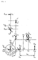
- FIG. 2 shows the point P, normal forces F N2 , F N1 of the concentrated loads at the point P, and a common normal n (a line of action of the concentrated load) at the point P by means of coordinate systems C 1 , C 2 and coordinate systems C q1 , C q2 .
- a shaft angle ⁇ , an offset E ( ⁇ 0, a distance between a point C 1 and a point C 2 ), and the directions of angular velocities ⁇ 1 , ⁇ 2 of two axes I, II are given. It is supposed that, when a common perpendicular of the two axes I, II is made to have a direction in which the direction of ⁇ 2 ⁇ ⁇ 1 is positive to be a directed common perpendicular v c , the intersection points of the two axes I, II and the common perpendicular v c are designated by C 1 , C 2 and a situation wherein the C 2 is on the C 1 with respect to the v c axis will be considered in the following. A case wherein the C 2 is under the C 1 would be very similar.
- Planes including the normal force F N2 (common normal n) of the concentrated load and parallel to each of the gear axes I, II are defined as planes of action G 1 , G 2 . Consequently, the F N2 (common normal n) exists on the line of intersection of the planes of action G 1 , G 2 .
- Cylinders being tangent to the planes of action G 1 , G 2 and having axes being the axis of each gear are defined as base cylinders, and their radii are designated by reference marks R b1 , R b2 .
- the coordinate systems C 2 , C q2 of a gear II are defined as follows.
- the origin of the coordinate system C 2 (u 2c , v 2c , z 2c ) is set at C 2
- its z 2c axis is set to extend into the ⁇ 2 direction on a II axis
- its v 2c axis is set as the common perpendicular v c in the same direction as that of the common perpendicular v c
- its u 2c axis is set to be perpendicular to both the axes to form a right-handed coordinate system.
- the plane of action G 2 is a plane tangent to the base cylinder (radius R b2 ).
- the common normal n is defined to be on the plane of action G 2 and also defined such that the common normal n is directed in the direction in which the q 2c axis component is positive
- an inclination angle of the common normal n from the q 2c axis can be expressed by ⁇ b2 (the direction shown in the figure is positive)
- the inclination angle of the common normal n in the coordinate system C 2 is defined to be expressed by the form of n 2c ( ⁇ 2 , ⁇ b2 ) by means of the inclination angles ⁇ 2 (the complementary angle of the ⁇ 2 ) of the plane of action G 2 to the directed common perpendicular v c , and the ⁇ b2 .
- the positive direction of the normal force F N2 of the concentrated load is the direction of the n and the q 2c axis direction component, and the z 2c axis direction component of the F N2 are designated by F q2 , F z2 , respectively.
- coordinate systems C 1 u 1C , v 1c , z 1c ), C q1 (q 1C , v q1c , z 1c ), a plane of action G 1 , a radius R b1 of the base cylinder, and the inclination angle n 1c ( ⁇ 1 , ⁇ b1 ) of the common normal n
- the relationship between the coordinate systems C 1 and C q1 can also be expressed by the following expressions (2).
- the coordinate systems C 1 and C 2 , and the coordinate systems C q1 and C q2 , all defined above, are the basic coordinate systems of the new tooth profile theory proposed newly by the inventor of the present invention.
- the basic coordinate systems make it possible that the application scope of the present invention can be considered to include a hypoid gear and a bevel gear as well as cylindrical gears.
- n( ⁇ 1 , ⁇ b1 ) and n ( ⁇ 2 , ⁇ b2 ) of the common normal n can be obtained as follows because the n exists on the line of intersection of the planes of actions G 1 , G 2 .
- Each axis direction component of the coordinate system C 2 of the n can be expressed as follows.
- each axis direction component of the coordinate system C 1 is expressed by each axis direction component of the coordinate system C 2 , it can be expressed as follows by means of the expressions (3).
- Fig. 3 shows the relationships among the point P on a path of contact, the common normal n, and a tangential plane W (shown by a line of intersection w with the plane of action G 2 ), and a point of contact P d , a common normal nd, and a tangential plane W d after the rotation of the former set by a minute angle ⁇ 2 in the coordinate systems C 2 and C q2 .
- the inclination angles of an arbitrary point of contact P and the common normal n at the point of contact P are expressed as follows by the coordinate system C 2 using the rotation angle ⁇ 2 of the gear II as a parameter.
- ⁇ 2 ( ⁇ 2 ) ⁇ /2 - ⁇ 2 ( ⁇ 2 )
- the point P When the point P is expressed by means of the aforesaid expressions (1) by the use of the coordinate system C q2 , the point P can be expressed as follows. P ⁇ q 2c ( ⁇ 2 ), -R b2 ( ⁇ 2 ), z 2c ( ⁇ 2 ) ⁇
- P d and n d can be expressed as follows.
- a plane of action passing through the point P d is designated by G 2d
- the gear II has been rotated by ⁇ 2 such that the G 2d has become parallel to the plane of action G 2
- the plane of action G 2d has moved to G 2de and the point P d has moved to P de
- the orthogonal projection of the point P de to the plane of action G 2 is designated by P df .
- the line of intersection of the plane of action G 2d and the tangential plane W d at the point P d is designated by w d
- the wd is expressed by w d ' passing at the point P df by being projected on the plane of action G 2 as a result of the aforesaid movement.
- n d is designated by n d '.
- the intersection point of the w d ' and a plane of rotation passing at the point P is designated by P dg .
- the w d ' is located at a position where the w d ' has rotated to the w by ⁇ 2 - ⁇ 2 on the plane of action G 2 as a result of the rotation by ⁇ 2 .
- the wd' inclines to the w by ⁇ b2 at the point P df . Consequently, the amount of movement PP dg of the w d ' to the w in the q 2c axis direction can be expressed as follows.
- ⁇ z 2c R b2 ( ⁇ 2 ) ( ⁇ 2 - ⁇ 2 )/ ⁇ tan ⁇ b2 ( ⁇ 2 ) + 1/tan ⁇ b2 ( ⁇ 2 ) ⁇
- ⁇ q 2c R b2 ( ⁇ 2 ) ( ⁇ 2 - ⁇ 2 )/ ⁇ tan ⁇ b2 ( ⁇ 2 )tan ⁇ b2 ( ⁇ 2 ) + 1 ⁇
- ⁇ R b2 (dR b2 /d ⁇ 2 ) ⁇ 2
- ⁇ b2 (d ⁇ b2 /d ⁇ 2 ) ⁇ 2
- ⁇ 2 (d ⁇ 2 /d ⁇ 2 ) ⁇ 2
- ⁇ b2 (d ⁇ b2 /d ⁇ 2 ) ⁇ 2
- the expressions (7) are basic expressions of the new tooth profile theory for describing a tooth profile. Furthermore, the expressions (7) are a first function of the present invention.
- the expressions (8) are a second function of the present invention.
- the point of contact P and the inclination angle of the common normal n at the point of contact P can be expressed by the following expressions (9), by means of the coordinate systems C 1 and C q1 by the use of the ⁇ 2 as a parameter.
- Fig. 4 shows point P in a coordinate system C r2 (u r2c , v r2c , z r2c ) rotating along with the gear II.
- the coordinate system C r2 has an origin C 2 and z 2c axis in common with the coordinate system C 2 and rotates around the z 2c axis by the ⁇ 2 .
- the expressions (12) is a third function of the present invention.
- the aforesaid expressions (12) and (13) generally express a tooth profile the ratio of angular velocity of which varies.
- the three-dimensional tooth profile theory described above directly defines the basic specifications (paths of contacts) of a pair of gears in a static space determined by the two rotation axes and the angular velocities of the pair of gears without the medium of a pitch body of revolution (a pitch cylinder or a pitch cone).
- Fig. 5 shows relationships among the normal force F N2 of the concentrated load of the gear II at the point of contact P shown in Fig. 2 and bearing loads B z2 , B vq2f , B vq2r , B q2f , B q2r by means of the coordinate system C q2 .
- the gear II is rigidly supported by bearings b 2a , b 2f and b 2r in both of its axis direction and its radius direction and the rigidity of the axis is sufficiently large.
- " ' " and """ indicate the orthogonal projection of a point or a vector, respectively, to an object plane.
- the positive directions of load directions are respective axis directions of the coordinate system C q2 .
- the situation of the gear I is the same.
- the aforesaid expressions (16) are simultaneous equations including unknown quantities ⁇ 1 , ⁇ 2 , F q1 , F q2 , and the expressions (16) are basic expressions for describing motions of a pair of gears the tooth profiles of which are given.
- the expressions (16) can only be applied to an area in which a path of contact is continuous and differentiable. Accordingly, if an area includes a point at which a path of contact is nondifferentiable (such as a point where a number of engaging teeth changes), it is necessary to obtain expressions for describing the motion in the vicinity of the point. It is not generally possible to describe a steady motion of a pair of gears only by the aforesaid expressions (16).
- Fluctuations of a load generated in the gear II because of the rotation of a pair of gears can be understood as fluctuations of the loads of the bearings b 2a , b 2f and b 2r to the stationary coordinate system C 2 . Accordingly, if each bearing load expressed in the coordinate system C q2 is transformed into an axis direction component in the coordinate system C 2 , the result can be expressed by the following expressions (17).
- B z2c B z2 (the z 2c axis direction load of the bearing b 2a )
- B u2cf B q2f cos ⁇ 2 - B vq2f sin ⁇ 2 (the u 2c axis direction load of the bearing b 2f )
- B v2cf B q2f sin ⁇ 2 + B vq2f cos ⁇ 2 (the v 2c axis direction load of the bearing b 2f )
- B u2cr B q2r cos ⁇ 2 - B vq2r sin ⁇ 2 (the u 2c axis direction load of the bearing b 2r )
- B v2cr B q2r sin ⁇ 2 + B vq2r cos ⁇ 2 (the v 2c axis direction load of the bearing b 2r )
- Fluctuation components of the bearing load can be expressed as follows by differentiation of the above expressions (17).
- the fluctuation components of the bearing load of the gear II at an arbitrary rotation angle ⁇ 2 can be expressed as fluctuation components of the following six variables.
- t designates a time hereupon.
- Each item of the aforesaid (1)-(5) is described in order.
- R b2 ( ⁇ 2 ) The base cylinder radius R b2 ( ⁇ 2 ) to which the common normal at a point of contact is tangent is constant (the constant value is designated by R b20 ). That is, the following expression is obtained.
- the ratio of angular velocity is constant (designated by i 0 ).
- the ratio of angular velocity i 0 of a pair of gears should be a given torque ratio (being constant owing to the supposition of the input and the output).
- Fig. 6 shows relationships among a plane of action G 20 on which fluctuations of a bearing load are zero, a base cylinder (radius R b20 ), a path of contact (common normal n) and the normal force F N2 of the concentrated load in the coordinate systems C 2 and C q2 . If the path of contact is the same straight line in all of the surfaces of action (including a zone in which a plurality of contacts are included), the path of contact is continuous and differentiable in all of the zones. Consequently, a steady motion having no fluctuations of a bearing load can be realized.
- a tooth profile II having no fluctuation of its bearing load can be obtained in accordance with the following expressions (21) by transforming the aforesaid expressions (19) into the coordinate system C r2 .
- the u r2c axis is supposed to coincide with the u 2c axis when the rotation angle ⁇ 2 is zero.
- a coordinate system rotating around the z 1c axis by the ⁇ 1 is assumed to the coordinate system C r1 (u r1c , v r1c , z r1c ) to the coordinate system C 1 .
- a tooth profile I having no fluctuations of bearing load can be obtained in accordance with the following expressions (22) by transforming the straight line into the coordinate system C r1 .
- a u r1c axis is supposed to coincide with a u 1c axis when the rotation angle ⁇ 1 is zero.
- the expressions (21), (23) show that the tooth profiles I, II are curves corresponding to the paths of contact on an involute helicoid. It is possible to use curved surfaces that include the tooth profiles I, II and do not interfere with each other as tooth surfaces. However, because the curved surfaces other than the involute helicoid or a tooth surface being an amended involute helicoid are difficult to realize the aforesaid path of contact and the common normal, those curved surfaces are not suitable for power transmission gearing.
- a pair of gears being objects having no fluctuation of a bearing load is defined as follows as described above.
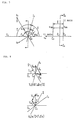
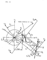
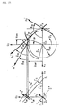
- Fig. 7 shows a relationship between a relative rotation axis and a coordinate system C S . If a positional relationship between two axes I and II and their angular velocities ⁇ 10 , ⁇ 20 are given, it is supposed that the intersection points of the common perpendicular v c (the positive direction thereof is the direction of ⁇ 20 ⁇ ⁇ 10 ) of the two axes with each of the axes I, II are designated by C 1 , C 2 , respectively, and the C 1 is located under the C 2 with respect to the v c .
- the I s is in a zone of 0 ⁇ ⁇ ⁇ ⁇ (the positive direction of the angle ⁇ is the counterclockwise direction) to the II S in accordance with the definition of ⁇ 20 ⁇ ⁇ 10 .
- the positive directions are shown in the figure.
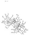
- Fig. 8 shows a relative velocity V s (vector) of the point C s .
- V s vector
- the expression is effective within a range of 0 ⁇ ⁇ s ⁇ ⁇ , and the location of the C s changes together with the ⁇ s , and the location of the point C s is located above the C 1 in case of 0 ⁇ ⁇ s ⁇ ⁇ /2, and the location of the point C s is located under the C 1 in case of ⁇ /2 ⁇ ⁇ s ⁇ ⁇ .
- the coordinate system C S (u c , v c , z c ) is composed of C s as its origin, the directed common perpendicular v c as its v c axis, the relative rotation axis S as its z c axis (the positive direction thereof is the direction of ⁇ r ), and its u c axis taken to be perpendicular to both the axes as a right-handed coordinate system.
- the coordinate system C s becomes a coordinate system fixed in the static space.
- the coordinate system C s is a basic coordinate system in case of treating a pair of gears performing the transmission of the motion of constant ratio of angular velocity together with the previously defined coordinate Systems C 1 , C 2 and their derivative coordinate systems.
- the relationships among the coordinate system C s and the coordinate systems C 1 , C 2 is schematically shown in Fig. 9.
- Fig. 18 shows a relationship between the given path of contact g 0 and a relative velocity V rs (vector) at an arbitrary point P on the g 0 .
- V rs vector
- V s vector
- [C 1 C s ] indicates a vector having the C 1 as its starting point and the C s as its end point
- [C 2 C s ] indicates a vector having the C 2 as its starting point and the C s as its end point.
- the relative velocity V rs exists on a tangential plane of the surface of a cylinder having the relative rotation axis S as an axis, and an inclination angle ⁇ to the V s on the tangential plane can be expressed by the following expression (33).
- Cos ⁇
- the g 0 is a directed straight line on a plane N perpendicular to V rs at the point P. If the line of intersection of the plane N and the plane S H is designated by H n , the H n is normally a straight line intersecting with the relative rotation axis S, through and the g 0 necessarily passing through the H n if an infinite intersection point is included. If the intersection point of the g 0 with the plane S H is designated by P 0 , then P 0 is located on the line of intersection H n , and the g 0 and P 0 become as follows according to the kinds of pairs of gears.
- the V rs simply means a peripheral velocity around the relative rotation axis S. Consequently, the plane N includes the S axis. Hence, H n coincides with the S, and the path of contact g 0 always passes through the relative rotation axis S. That is, the point P 0 is located on the relative rotation axis S. Consequently, as for these pairs of gears, the path of contact g 0 is an arbitrary directed straight line passing at the arbitrary point P 0 on the relative rotation axis.
- pairs of gears with an identical path contacts g 0 have an identical tooth profile corresponding to g 0 , with the only difference between them being which part of the tooth profile is used effectively. Consequently, in a design of a pair of gears, it is important at which position in a static space determined by the two axes the path of contact g 0 is disposed. Further, because a design reference point is only a point for defining the path of contact g 0 in the static space, it does not cause any essential difference at which position on the path of contact g 0 the design reference point is selected.
- the g 0 When an arbitrary path of contact g 0 is given, the g 0 necessarily intersects with a plane S H with the case where the intersection point is located at an infinite point. Accordingly, even when the intersection point is set as a design reference point, generality is not lost.
- it is designed to give the arbitrary point P 0 on the plane S H (on a relative rotation axis in case of cylindrical gears and a bevel gear) as the design reference point.
- Fig. 11 shows the design reference point P 0 and the path of contact g 0 by the use of the coordinate system C s .
- P 0 u c0 , v c0 , z c0
- each coordinate value can be expressed as follows.
- u c0 O s
- v c0 0
- z c0 C s O s
- u c0 0.
- the point O s is the intersection point of a plane S s , passing at the design reference point P 0 and being perpendicular to the relative rotation axis S, and the relative rotation axis S.
- V rs0 ⁇ r ⁇ [u c0 ] + V s
- [u c0 ] indicates a vector having the O s as its starting point and the P 0 as its end point.
- the ⁇ 0 is supposed to be positive when u c0 ⁇ 0, and the direction thereof is shown in Fig. 10.
- a plane passing at the point P 0 and being perpendicular to V rs0 is designated by S n
- the plane S n is a plane inclining to the plane S s by the ⁇ 0
- the path of contact g 0 is an arbitrary directed straight line passing at the point P 0 and located on the plane S n .
- the inclination angle of the g 0 in the coordinate system C s can be defined with the inclination angle ⁇ 0 of the plane S n from the plane S s (or the v c axis) and the inclination angle ⁇ n0 from the plane S p on the plane S n , and the defined inclination angle is designated by g 0 ( ⁇ 0 , ⁇ n0 ).
- the positive direction of the ⁇ n0 is the direction shown in Fig. 11.
- Fig. 9 shows relationships among the coordinate system C s , the planes S H , S s , S p and S n , P 0 and g 0 ( ⁇ 0 , ⁇ n 0 ).
- the plane S H defined here corresponds to a pitch plane in case of cylindrical gears and an axis plane in case of a bevel gear according to the conventional theory.
- the plane S s is a transverse plane, and the plane S p corresponds to the axis plane of the cylindrical gears and the pitch plane of the bevel gear.
- the plane S n is a normal plane expanded to a general gear
- the ⁇ n0 and the ⁇ 0 also a normal pressure angle and a helical angle expanded to a general gear, respectively.
- pressure angles and helical angles of ordinary pairs of gears can be expressed uniformly to static spaces as inclination angles to each plane of common normals (the g 0 's in this case) of points of contact.
- the planes S n , ⁇ n0 , ⁇ 0 defined here coincide with those of a bevel gear of the conventional theory, and differ for other gears because the conventional theory takes pitch planes of individual gears as standards, and then the standards change to a static space according to the kinds of gears.
- the path of contact g 0 is determined in a static space by the selections of the independent variables of two of (the z c0 ), the ⁇ n0 and the ⁇ 0 in case of cylindrical gears because the z c0 has no substantial meaning, three of the z c0 , the ⁇ n0 and the ⁇ 0 in case of a bevel gear, or three of the z c0 , the ⁇ n0 and the ⁇ 0 (or the u c0 ) in case of a hypoid gear, a worm gear or a crossed helical gear.
- Fig. 12 shows the path of contact g 0 in coordinate systems O 2 , O q2 , O 1 , O q1 .
- the coordinate systems O 2 (u 2 , v 2 , z 2 ), O q2 (q 2 , v q2 , z 2 ) are coordinate systems having an origin at the intersection point O 2 of a plane of rotation Z 20 of the axis of the gear II passing at the design reference point P 0 with the axis of the gear II, and the coordinate systems O 2 and O q2 are the coordinate systems C 2 , C q2 displaced by C 2 O 2 in the z 2c axis direction in parallel.
- the coordinate systems O 1 (u 1 , v 1 , z 1 ), O q1 (q 1 , v q1 , z 1 ) are similarly coordinate systems having an origin being an intersection point O 1 of a plane Z 10 lying immediately under the axis of the gear I passing at the point P 0 with the axis of the gear I, and the coordinate systems O 1 and O q1 are the coordinate systems C 1 and C q1 displaced by C 1 O 1 in the z 1c axis direction in parallel.
- the inclination angle of the g 0 on the coordinate system O 2 can be expressed as g 0 ( ⁇ 20 , ⁇ b20 ) by means of the inclination angle ⁇ 20 (the complementary angle of the ⁇ 20 ) from the v 2 axis of the plane of action G 20 and the inclination angle ⁇ b20 from the q 2 axis on the plane of action G 20 .
- the plane of action G 10 is defined, and the inclination angle of the g 0 can be expressed as g 0 ( ⁇ 10 , ⁇ b10 ) by means of the coordinate system O 1 .
- Each axis direction component of the coordinate system O 2 can be expressed as follows by means of expressions (31) using each axis direction component of the coordinate system C s .
- the g 0 ( ⁇ 20 , ⁇ b20 ) is concluded as follows.
- the g 0 ( ⁇ 10 , ⁇ b10 ) is concluded as follows.
- a design reference point is given at P 0 (u c0 , 0, z c0 ) by the coordinate system C s .
- z c0 ⁇ 0 and u c0 0 especially in case of cylindrical gears and a bevel gear. Consequently, if the design reference point expressed by the coordinate system O 2 is designated by P 0 (u 2p0 , -v cs2 , 0), u 2P0 can be expressed as follows by means of the expressions (31).
- u 2p0 O 2s
- P 0 -u c0 cos ⁇ s + z c0 sin ⁇ s
- the g 0 ( ⁇ 20 , ⁇ b20 ) is given by the aforesaid expressions (35) and (36), if the P 0 (u 2p0 , -v cs2 , 0) is expressed by the P 0 (q 2p0 , -R b20 , 0) by transforming the P 0 (u 2p0 , -v cs2 , 0) into the coordinate system O q2 , the q 2p0 and the R b20 are as follows.
- q 2p0 u 2p0 cos ⁇ 20 - v cs2 sin ⁇ 20
- Fig. 15 shows the path of contact g 0 and the corresponding tooth profile I. Because g 0 ( ⁇ 10 , ⁇ b10 ) is given by the aforesaid expressions (37) and (38), if the design reference point P 0 (u c0 , 0, z c0 ) is transformed into the coordinate systems O 1 and O q1 to be expressed by P 0 (u 1p0 , -v cs1 , 0) and P 0 (q 1p0 , -R b10 , 0) quite similarly to the case of coordinate system O 2 , u 1p0 , q 1p0 and R b10 are concluded as follows by means of the aforesaid expressions (30).
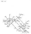
- Fig. 14 shows a tooth profile II using a coordinate system O r2 (u r2 , v r2 , z r2 ) rotating at the ⁇ 2 together with the gear II.
- Fig. 15 shows a tooth profile I in a coordinate system O r1 (u r1 , v r1 , z r1 ) rotating at ⁇ 1 together with the gear I and the coordinate system O1.
- an involute pair of gears being objects of the invention is defined as follows. If the tooth profiles corresponding to the path of contact g 0 are severally supposed to be the tooth profiles I, II, an involute helicoid including the tooth profile II is given as the tooth surface II, and a curved surface generated by the tooth surface II at the constant ratio of angular velocity i 0 is supposed to be the tooth surface I (consequently including the tooth profile I). If the tooth surfaces of the involute pair of gears defined in such a way are made to contact with each other along the tooth profiles I, II, fluctuations of a bearing load become zero.
- the involute pair of gears becomes the most advantageous pair of gears as a pair of gears for power transmission in view of the fluctuations of a load.
- the relational expression of the involute pair of gears i.e. equations of the involute helicoid, the surface of action thereof and the conjugate tooth surface I thereof, are described.
- the line of intersection of the tangential plane W 0 and the G 20 at the point P 0 is shown as a straight line w 0 . It is assumed that the point of contact P 0 has moved to the P and the w 0 has moved to the w when the gear II has rotated by ⁇ 2 .
- the tooth surface normal n of an arbitrary point on the w is located on the plane of action G 20 and the inclination angle ⁇ b20 of the tooth surface normal n from the q 2 axis is constant in accordance with the definition of the involute helicoid, the tooth surface normal n is a straight line passing at the point P on the g 0 and perpendicular to g 0 .
- the involute helicoid can be defined to be a trajectory surface drawn by the line of intersection w, moving on the G 20 in the q 2 axis direction by R b20 ⁇ 2 in parallel together with the rotation of the gear II (rotation angle is ⁇ 2 ), in a rotating space (the coordinate system O r2 ) fixed to the gear II. Then, if an arbitrary point on the straight line w is designated by Q and the point Q is expressed by the coordinate system O r2 , the involute helicoid to be obtained can be expressed as a set of Q values.
- the Q(u 2 , v 2 , z 2 ) is found as follows.
- the locus of the straight line w draws an involute helicoid (the base cylinder radius thereof: R b20 , the helical angle thereof: ⁇ b20 ). Accordingly, it is supposed that the locus of the straight line w is given as the tooth surface II. At this point, the directed straight line n at the point Q is the tooth surface normal n.
- Fig. 17 shows an arbitrary point P m on an involute helicoid (the tooth surface II) passing at the straight line w at the rotation angle ⁇ 2 in the coordinate system O 2 . If it is supposed that the w is at w m when the tooth surface II has further rotated from the w by ⁇ 2 , the intersection point Q m of the w m and the n can be expressed as follows.
- a rotary coordinate system O r2m is a coordinate system that coincides with the coordinate system O 2 when the rotation angle ⁇ 2 and rotates by the ⁇ 2 around the z 2 axis
- Q m (u r2m , v r2m , z r2m ) can be expressed by the coordinate system O r2m as follows.
- the Q m moves to the P m . Because the point Q m on the coordinate system O r2m is the point P m on the coordinate system O 2 and both of points have the same coordinate values, the P m (u 2m ,v 2m ,z 2m ) becomes as follows if the point P m is expressed by the coordinate system O 2 .
- the expressions (55) are equations of the involute helicoid (the tooth surface II) passing at the point P on the path of contact g 0 at the arbitrary rotation angle ⁇ 2 and using the z 20 and the ⁇ 2 as parameters by the coordinate system O 2 .
- supposing z 20 0, the expressions (55) become the expressions (50), i.e. the tooth profile II passing at the point P 0 .
- the expressions (55) can be considered as the equations of the point P m on a plane G 2m , being the point Q m on the plane of action G 20 rotated by the ⁇ 2 into the reverse direction of the ⁇ 2 , by the coordinate system O 2 .
- the involute helicoid passing at the point P is examined on the coordinate system O 2 , the latter interpretation simplifies analysis.
- the line of contact passing at the point P is a combination of the z 20 and the ⁇ 2 , both satisfying the requirement for contact when the ⁇ 2 is fixed. Consequently, the line of contact can be obtained as follows by the use of the ⁇ 2 as a parameter.
- Fig. 18 shows a line of contact PP m and a common normal n m (P m0 P m ) at the point of contact P m . It is assumed that the gear II has rotated by the ⁇ 2 and the point of contact is positioned at the point P on the path of contact g 0 .
- the point of contact P m other than the P is set on the tooth surface II, and the relative velocity of the point of contact P m is designated by V rsm , and the common normal of the point of contact P m is designated by n m (
- 1).
- an inclination angle on the plane S pm to the plane S H is designated by ⁇ m0 .
- S nm a plane passing at the point P m0 and being perpendicular to the V rsm0
- the plane S nm includes the n m (P m0 P m ). Consequently, the plane S nm is a normal plane (the helical angle thereof: ⁇ m0 ) at the point P m .
- the inclination angle of the n m expressed by the coordinate system O 2 is given by n m ( ⁇ 20 + ⁇ 2 , ⁇ b20 ).
- the helical angle ⁇ m0 of the plane S nm can be expressed as follows by the use of the transformation expression (40) of the inclination angle between the coordinate system C s and the coordinate system O 2 .
- the expression (58) indicates the locus P 0 P m0 of the common normal n m of the point of contact on the plane S H . Because P m0 is an intersection point of the locus P 0 P m0 (the aforesaid expression (58)) and the line of intersection H g2m of the plane of action G 2m and the plane S H , P m0 can be expressed as follows by the coordinate system O 2 by the use of ⁇ 2 as a parameter.
- u 2m0 R b20 /cos( ⁇ 20 + ⁇ 2 ) - v cs2 tan( ⁇ 20 + ⁇ 2 )
- the common normal n m can be expressed on the plane of action G 2m by the use of ⁇ 2 as a parameter as a directed straight line passing at the point P m0 and having an inclination angle of n m ( ⁇ 20 + ⁇ 2 , ⁇ b20 ).
- Fig. 19 shows relationships among points Q m0 (P m0 ), Q m (P m ), Q and the point P on the plane of action G 20 .
- the P m0 and the P m are expressed by a rotary coordinate system O r2m
- the plane of action G 2m rotates by the phase difference ⁇ 2 to be superposed on the plane of action G 20 .
- the n m moves to the n
- the P m0 moves to the Q m0
- the P m moves to the Q m .
- z 2m0 - ⁇ q 2 ( ⁇ 2 , ⁇ 2 ) - q 2m0 ⁇ tan ⁇ b20 + ⁇ q 2p - q 2 ( ⁇ 2 , ⁇ 2 ) ⁇ /tan ⁇ b20 + z 2p
- the point Q m can be expressed as follows by means of the coordinate system O q2 by the use of the ⁇ 2 as a parameter.
- q 2m ( ⁇ 2 , ⁇ 2 ) q 2 ( ⁇ 2 , ⁇ 2 ) + R b20 ⁇ 2 cos 2 ⁇ b20
- z 2m ( ⁇ 2 , ⁇ 2 ) z 2 ( ⁇ 2 , ⁇ 2 ) + R b20 ⁇ 2 cos ⁇ b20 sin ⁇ b20
- the expressions (61) are the equations of the line of contact (PP m ) at the arbitrary rotation angle ⁇ 2 in the coordinate system O 2 using ⁇ 2 as a parameter.
- the parameter z 20 of the aforesaid expressions (55) is a function of ⁇ 2 from the requirement for contact. Consequently, by changing ⁇ 2 , the surface of action can be expressed as a set of lines of contact.
- the expressions (61) can express the surface of action as a set of the common normals n m by changing ⁇ 2 .
- the surface of action is a distorted curved surface drawn by the directed straight line (P m0 P m ) of the helical angle ⁇ b20 on the plane of action by changing the inclination angle ⁇ 20 + ⁇ 2 of the directed straight line with the displacement of the gear II in the axis direction.
- Fig. 20 shows the point of contact P m and the common normal n m (P m0 P m ) in the coordinate systems O 1 and O q1 .
- the point of contact P m given by the aforesaid expressions (61) is expressed by the coordinate systems O 1 , O q1 to be transformed into the coordinate system O r1 , the transformed point of contact P m expresses the tooth surface I.
- each coordinate value can be expressed as follows by coordinate transformation expressions of the coordinate systems O 2 and O 1 .
- the n m ( ⁇ 1m , ⁇ b1m ) can be obtained as follows by means of the aforesaid expressions (41) and (42), which are transformation expressions of the inclination angles between the coordinate systems O 2 and O 1 .
- the point P 0 and the normal n 0 thereof can be expressed as follows by means of the coordinate system O 2 .
- E can be obtained by giving the shaft angle ⁇ and the ratio of angular velocity i 0 (or a shaft angle ⁇ s of a relative rotation axis), and the relative rotation axis S and the mating gear axis I, i.e. a pair of gears, are determined.
- Fig. 21 a conceptual drawing of an involute gear group in the case where the gear II is rotated and the point P 0 and the normal n 0 thereof are selected to be fixed at an appropriate position of the coordinate system O 2 to be a design reference point and a path of contact.
- S designates a relative rotation axis of a helical gear and a worm gear (or a crossed helical gear)
- S b designates a relative rotation axis of a bevel gear
- S hy designates a relative rotation axis of a hypoid gear.
- the involute gear group changes as follows in accordance with the locations of the point P 0 .
- Japanese Patent Laid-Open Publication No. Hei 9-53702 proposes a method for describing a design method of gears uniformly from a gear having parallel two axes such as a spur gear, a helical gear or the like, which is the most popular gear type, to a hyperboloidal gear having two axes not intersecting with each other and not being parallel to each other such as a hypoid gear.
- a gear having parallel two axes such as a spur gear, a helical gear or the like, which is the most popular gear type
- a hyperboloidal gear having two axes not intersecting with each other and not being parallel to each other such as a hypoid gear.
- the hyperboloidal gear especially, there are often cases where sufficient surface of action cannot be obtained with some combinations of selected variables.
- An involute face gear is a pair of gears having a pinion being an involute spur gear and a large gear forming a pinion tooth surface and a conjugate tooth surface thereof on a side face of a disk (a plane perpendicular to the axis of the disk).
- the involute face gear is conventionally well known, and can be designed and manufactured relatively easily to be used as a gear for light loads.
- Some of the involute face gears use a helical gear in place of the spur gear. However, the use of the helical gear makes the design and the manufacturing of the involute face gear difficult. Consequently, the involute face gear using the helical gear is less popular than that using the spur gear.
- a reference pinion cone (or a reference pinion cylinder) is given.
- a tooth curve being tangent to a relative velocity on a curve (pitch contact locus) being tangent to the body of revolution of a mating gear being tangent to the reference pinion cone is set to be a pinion surface line.
- the pinion tooth surface is formed as a screw helicoid, unlike the involute hypoid gear of the present invention. If an involute tooth surface is employed in a pinion in the design method, there are cases where an effective tooth surface of a gear cannot,be obtained to a gear having a small gear ratio, i.e. having a small pinion diameter.
- a Gleason type hypoid gear uses a conical surface, and both of its pinion and its gear form their teeth in a conical surface state.
- the helical angle ⁇ 0p (being different from the helical angle ⁇ 0 according to the present invention strictly) of its pinion is fixed at about 50°.
- a gear ratio, an offset, a gear width, all empirically effective nearby the fixed helical angle ⁇ 0p are given as standards. Thereby, specifications are generated such that an almost constant asymmetric pressure angle (e.g. 14°-24°, or 10°-28°) may be effective. That is a method, so to speak, for determining a gear shape geometrically analogous to a reference gear shape.
- involute helicoidal tooth surfaces D and C can be determined when the design reference point P 0 (R 20 , ⁇ 0 ) and two tooth surface normals g 0D ( ⁇ 0 , ⁇ n0D ; C s ) and g 0C ( ⁇ 0 , ⁇ n0C ; C s ) passing at the point P 0 are given.
- the tooth surfaces D and C are a drive side tooth surface and a coast side tooth surface of a pair of gears, and the g 0D and the g 0C are normals of respective tooth surfaces, i.e. paths of contact.
- the shaft angle ⁇ , the offset E, the gear ratio i 0 , the radius R 20 or R 10 of a design reference point are given in the aforesaid design method of a face gear, relationships among a contact state of a tooth surface and three variables of ⁇ 0 , ⁇ n0D and ⁇ n0C are not made to be clear. Consequently, the selection cannot be executed, and there are cases wherein an effective tooth surface cannot be obtained.
- a surface of action of a pair of gears a tooth surface of one of which is an involute helicoid is obtained.
- a selection method of three variables of ⁇ 0 , ⁇ n0D and ⁇ n0C the effective tooth surfaces of which exist in a surface of action given by a pinion and a gear, and the specifications of teeth having no sharpened top or undercut by means of an equivalent rack, which will be described later, are determined.
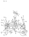
- Fig. 22 and the following show size specifications of a hypoid gear.
- the coordinate systems C s , C 1 and C 2 are determined based on the aforesaid specifications.
- the gear I is supposed to be a pinion
- the gear II is supposed to be a gear.
- the process of determining an involute helicoid surface of a pinion for obtaining the effective gear tooth surfaces D and C in a zone enclosed by a given large end radius and a given small end radius of a gear on a disk in the case where the pinion is formed to be a cylinder shape and the involute helicoid is given to the pinion.
- a rack (equivalent rack) moving on a plane formed by two paths of contact when the paths of contact g 0D and g 0C of the tooth surfaces D and C on the drive side and the coast side are given as the two directed straight lines intersecting at the design reference point.
- teeth effective as the teeth of a gear can be formed in the vicinity of the design reference point.
- the descriptions concerning the equivalent rack in this paragraph can be applied not only to the hypoid gear but also to gears in the other expressions.
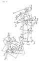
- Fig. 23 conceptually shows relationships among planes S H , S p and S n of a hypoid gear and a plane S t formed by velocities V 10 , V 20 at the point P 0 .
- the plane S n is a plane perpendicular to the relative velocity V rs0 at the P 0 .
- the relative velocity V rs0 is located on the plane S p .
- the plane S t also includes V rs0 , the plane S t and the plane S p intersect with each other with the relative velocity V rs0 as a line of intersection.
- the plane S t and the plane S n cross with each other at right angles, and have a normal velocity V gt0 on the plane S t as the line of intersection g t (positive in the direction of the V gt0 ). That is, the plane S t is a plane formed by the rotation of the plane S p around V rs0 as an axis on the plane S n by ⁇ nt , and corresponds to the conventional pitch plane.
- peripheral velocities V 10 , V 20 of the point P 0 are expressed as follows.
- V 10 ⁇ 10 ⁇ [O 1n P 0 ]
- V 20 ⁇ 20 ⁇ [O 2n P 0 ]
- [AB] indicates a vector having a point A as its starting point and a point B as its end point. Because O 1n P 0 is located on the plane S n , the O 1n P 0 is perpendicular to the relative velocity V rs0 , and is perpendicular to the V 10 owing to the aforesaid expression. Consequently, the O 1n P 0 is perpendicular to the plane S t at the point P 0 . Quite similarly, because O 2n P 0 is perpendicular to the V rs0 and the V 20 , the O 2n P 0 is perpendicular to plane S t at the point P 0 .
- the points O 1n , P 0 and O 2n are located on a straight line.
- the straight line is set to be a design criterion perpendicular C n (positive in the direction from the O 1n to the O 2n ).
- the C n is the line of centres of a pair of gears passing at the point P 0 . The relationship does not depend on the position of the point P 0 .
- an arbitrary plane including the relative velocity V rso can be the tangential plane of a tooth surface passing at the point P 0
- a tooth surface having a tangential plane W N (perpendicular to the plane S t ) including the design criterion perpendicular C n has the g t as its path of contact (contact normal).
- the tangential plane of a tooth surface passing the point P 0 is appropriately inclined to the plane W N formed by the V rso and the C n
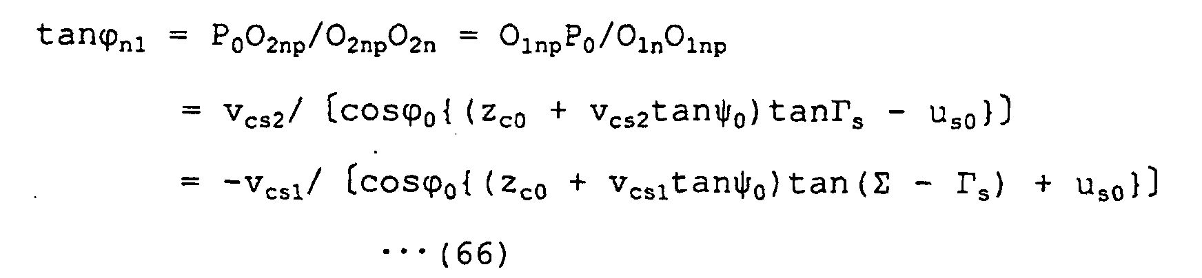
- the path of contact g 0 (contact normal) thereof is inclined on the plane S n on the basis of the g t . Accordingly, if g t is a limiting path g t , the inclination angle g t ( ⁇ 0 , ⁇ nt ; C s ) of the limiting path g t can be obtained as follows.
- Fig. 24 draws the design criterion perpendicular C n on the plane S n and the limiting path g t perpendicular to the C n . If the feet of perpendicular lines drawn from the points O 1n , O 2n to the plane S p (perpendicular to the plane S n ) are designated by O 1np , O 2np , the ⁇ nt can be obtained as follows.
- each directed line segment has its positive direction being the positive direction of the each axis of the coordinate system C s .
- v cs2 , v cs1 , u c0 , z c0 can be expressed as follows by means of the coordinate systems O 1 , O 2 .
- v cs2 Etan ⁇ s / ⁇ tan ⁇ s + tan( ⁇ - ⁇ s ) ⁇
- the changed expressions (66) become as follows.
- the limiting path g t inclines by ⁇ nt to the plane S p on the plane S n .
- the ⁇ nt has its positive direction in the clockwise direction when it is viewed to the positive direction of the z c axis.
- Fig. 25 shows an equivalent rack on the plane S n shown from the positive direction of the relative velocity V rs0 .
- peripheral velocities V 10 , V 20 can be expressed as follows on the plane S t .
- V 10 V gt0 + V s10
- V 20 V gt0 + V s20
- V 10 (V g0D + V WsD ) + V s10
- V 20 (V g0D + V WsD ) + V s20
- V gt0 V g0D + V WsD
- V gt0 V g0C + V WsC
- V g0D V gt0 cos( ⁇ n0D - ⁇ nt )
- V g0C V gt0 cos( ⁇ nt - ⁇ n0C )
- V gt0 R b2gt (d ⁇ 2 /dt) cos ⁇ b2gt
- V g0D R b20D (d ⁇ 2 /dt) cos ⁇ b20D
- V g0C R b20C (d ⁇ 2 /dt)cos ⁇ b20C
- the normal velocities V gt0 , V g0D , V g0C are always constant. Consequently, the normal velocities V g0D , V g0C of the arbitrary points P D , P C on the g 0D and the g 0C can always be expressed by the expressions (67).
- the points of contact on the g 0D , g 0C owing to the rotation of a gear are expressed by the points of contact of a rack having the gt as its reference line and the same paths of contact g 0D , g 0C (having the w sD and the w sC as its tooth profiles) and moving at V gt0 in the direction of the g t .
- the rack is defined as an equivalent rack
- the equivalent rack is a generalized rack of a spur gear having an involute of zero.
- the w sD and the w sC are inclined by ( ⁇ n0D - ⁇ nt ) and ( ⁇ nt - ⁇ n0C ) to the C n (perpendicular to the g t ), respectively.
- the limiting path g t indicates the reference line of an equivalent rack
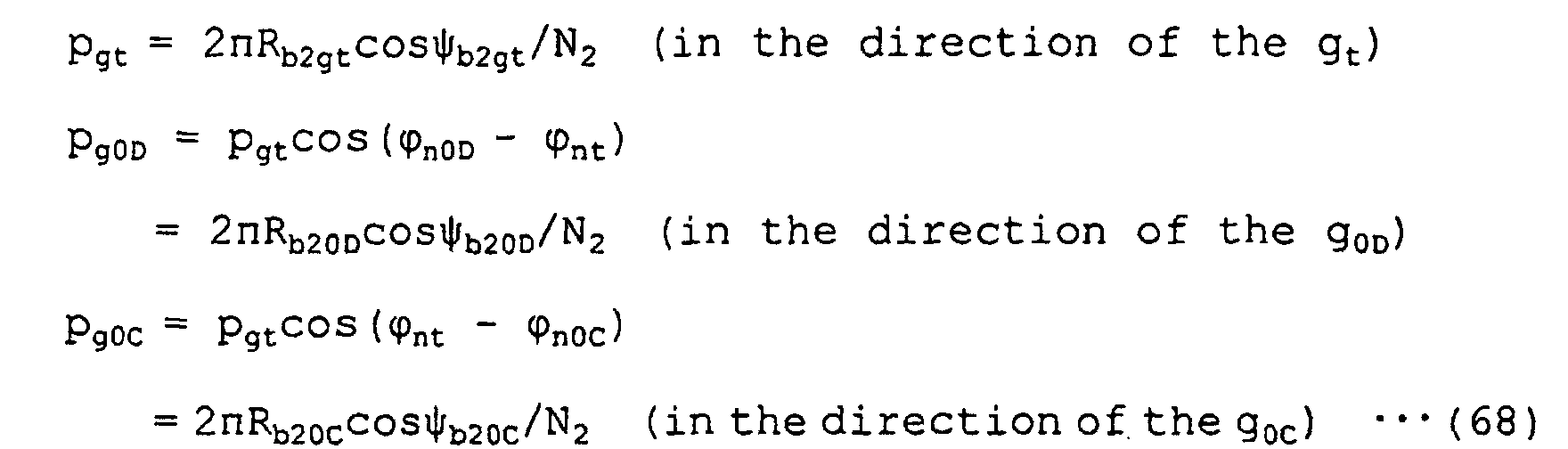
- the reference pitch p gt and the normal pitchs p n0D , p n0C can be expressed as follows.
- N 2 is the number of teeth of the gear II.
- a critical tooth depth h cr (R CD R CDH ), at which the top land of the equivalent rack is zero, can be expressed as follows with attention to the fact that the R CD R CDH crosses with the g t at right angles.
- h k h cr - 2t cn / ⁇ tan( ⁇ n0D - ⁇ nt ) + tan( ⁇ nt - ⁇ n0C ) ⁇ - 2c r
- the point Q 2n is selected in order that both of the paths of contact g 0D , g 0C may be included in an effective zone and the A d2 ⁇ 0 when the Q 2n is located on the O 1n side to the point P 0 .
- P 0 P C - ⁇ A d2 + (h cr - h k )/2 ⁇ sin( ⁇ n0D - ⁇ n0C )/cos( ⁇ n0D - ⁇ nt )
- the positive direction of the P 0 P C is the direction of g 0C .
- the w sC is located at a position delayed by ⁇ 2wsC to the w sD . Thereby, the position of the w sC to the point P 0 (w sD ) has been determined.
- phase angle of the w sC to the w sD is determined by the generalization of the concept of a tooth thickness in the conventional gear design (how to determine the tooth thickness of a rack on the g t ), the phase angle is determined by giving a working depth and an addendum in the present embodiment.
- a tooth profile corresponding to an arbitrarily given path of contact exists mathematically. However, only one tooth profile can actually exist on one radius arc around a gear axis at one time. Consequently, a tooth profile continuing over both the sides of a contact point of a cylinder having the gear axis as its axis with a path of contact does not exist actually. Therefore, the contact point is the action limit point of the path of contact. Furthermore, this fact indicates that the action limit point is the foot of a perpendicular line drawn from the gear axis to the path of contact, i.e. the orthogonal projection of the gear axis.
- R 2 q 2 2 + R b2 2
- an action limit point P 2k concerning the gear II can be obtained.
- the shape of a surface of action is relatively simple, and there is no case where it becomes impossible to form any tooth surface according to the setting way of a design reference point P 0 as long as the design reference point P 0 is located within an ordinary range. Furthermore, even if no tooth surface can be formed by a given design reference point P 0 , amendment of the design reference point P 0 remains relatively easy.
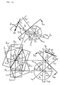
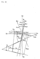
- Fig. 26 shows relationships among limiting paths g 2z , g t , paths of contact g 0D , g 0C and their equivalent rack on the plane S n .
- the limiting path g 2z is a line of intersection of the plane S n with a right side plane Z 20 immediately below the gear axis
- the limiting path g t is a line of intersection of the plane S n with a plane S t forming the line velocity of the point P 0
- the selection of the design reference point P 0 is the selection of a position in a static space where the shape of the equivalent rack is given.
- a pinion has a cylindrical shape and the shape of the teeth of the pinion is constant (only the phase angles thereof change) in the direction of the axis thereof.
- the shape of teeth of a gear changes from the small end thereof to the large end thereof.
- Each ⁇ 0 being inclinations of the plane S n perpendicular to the relative velocity at the design reference point P 0 is selected as follows. Because the line of intersection of the plane S n with the plane of rotation Z 20 of the gear axis passing the point P 0 is the limiting path g 2z , the inclination angles g 2z ( ⁇ 0 , ⁇ n2z ; C s ) and g 2z ( ⁇ 2z , 0; C 2 ) of the limiting path g 2z can be obtained from the following expressions.
- tan ⁇ n2z sin ⁇ 0 /tan ⁇ s
- tan ⁇ 2z tan ⁇ 0 /sin ⁇ s
- the face and root surface of a large gear are formed as planes of rotation of gear in the present embodiment, the tangential planes of tooth surface of a large gear should be inclined mutually in the reverse directions to the plane of rotation of the large gear to each other in order that a tooth of the large gear may have an ordinary shape of a trapezoid. Consequently arbitrary paths of contact g 0D and g 0C should be located in the vicinity of the limiting path g 2z and should be inclined in the mutually reverse directions to the g 2z .
- the tooth surface of the gear should approximately satisfy the following relationships in order that the tooth surface may be effective at a radius equal to the small end radius R 2t of the gear or more.
- ⁇ 20 0 in case of a bevel gear.
- the design reference point P 0 and the limiting paths g 2z , g t are determined on the plane S H by the coordinate system C s as follows.
- u c0 Esin ⁇ s cos ⁇ s tan ⁇ 0
- the R 20 and the ⁇ 0 determined as described above should be regarded as first rank approximates, and there are cases where the R 20 and the ⁇ 0 are adjusted according to the state of the tooth surface obtained as a result of the method described above. Furthermore, if needed values of an offset and a face width of a large gear are too large, there are cases wherein suitable R 20 and ⁇ 0 giving a satisfactory tooth surface do not exist.
- the tangential planes w sD and w sC of a tooth surface of a gear are inclined to the plane of rotation of gear Z 20 in the mutual reverse directions in order that the teeth of the gear may have a necessary strength. Consequently, the paths of contact g 0D , g 0C should be selected to be inclined to the limiting path g 2z in the mutual reverse directions. That is, the inclinations of the paths of contact g 0D , g 0C are selected to satisfy the following expression. ⁇ n0C ⁇ ⁇ n2z ⁇ ⁇ n0D
- ⁇ n0D ⁇ n2z + 38°
- ⁇ n0C ⁇ n2z + 38°
- ⁇ n2z ⁇ n0D
- ⁇ n0C ⁇ n2z - 38°
- ⁇ n0C ⁇ n2z - 19°
- ⁇ n0D ⁇ n2z + 19°
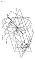
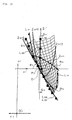
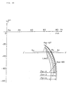
- Figs. 27-30 show surfaces of action in a case where a pinion is given an involute helicoid (the base cylinder radius thereof: R b12z , the plane of action helical angle thereof: ⁇ b12z ) the tooth surface normal of which is the limiting path g 2z .
- Fig. 27 is a sketch map for making the whole shape of a curved surface to be easy to understand.
- the expression of a surface of action is quite similar to that in the case where an involute helicoid is given to a large gear, the expression can be obtained by replacing the suffix 2 in the expressions (61) with 1.
- Only a tooth surface normal that satisfies the requirement for contact among the tooth surface normals of the involute helicoid becomes a contact normal.
- a tooth surface normal can be a contact normal at two positions of the both sides of the contact point to the base cylinder. Consequently, the curved surfaces shown in Figs. 28-30 are drawn.
- Loci of action limit curve (action limit point) of a pinion and a large gear of paths of contact are designated by L 1A (on a pinion base cylinder), L 2AD and L 2AC .
- orthogonal projections (action limit point on the gear axis side) to the surfaces of action of the large gear axis are designated by L 3AD and L 3AC which are the loci of the contact point of a cylinder having the large gear axis as its axis with an intersection line of the surface of action with a plane of rotation Z 2 .
- the orthogonal projection to the surface of action of the pinion axis (the action limit curve on the pinion side) is the L 1A .
- the surface of action becomes a plane, such that consequently the orthogonal projection of the surface of action of a pinion axis and a large gear axis become a simple straight line.
- the orthogonal projections of a pinion axis and a large gear axis do not become a straight line.
- the orthogonal projections generate ramifications.
- a zone enclosed by a action limit curve nearest to the design reference point P 0 is a substantially usable tooth surface.
- the large end of the large gear and the line of intersection of the small end cylinder with the surface of action are designated by R 2h , R 2t , respectively.
- a surface of action including the limiting path g 2z and enclosed by the L 3AD and the L 3AC is limited to a narrow zone near to the P 0 , there is no tooth surface that can substantially be used. Accordingly, an effective surface of action enclosed by the action limit curve, the face surface of the large gear, and large end and small end cylinders are as described in the following.
- Fig. 26 shows the shape of an equivalent rack on the plane S n . If a design reference point P 0 , a reference line (limiting path) g t of the equivalent rack and paths of contact g 0D , g 0C are given, the specifications and a position of the equivalent rack to the design reference point P 0 can be obtained as follows.
- a pinion face surface is supposed to be a cylinder passing the point Q 1n in accordance with the large gear face surface
- the pinion involute helicoid determined as above has the following practical disadvantages in the case where the tooth surfaces D, C severally have leads different from each other.
- the pinion top land may not be constant, and it may be necessary to determine the location of the pinion in the axial direction and to manufacture tooth surfaces separately, and so forth.
- the pinion involute helicoid is somewhat modified as follows for making the leads of the tooth surfaces D and C equal.
- Various methods for making the leads of the tooth surfaces D and C equal can be considered.
- tooth surface D is left to be the given original form, and that tooth surface C is changed to be a tooth surface C c by the adjustment of only its helical angle ⁇ b10C (with base cylinder radius R b10C being left as it is).
- tan ⁇ b10CC R b10C tan ⁇ b10D /R b10D
- the inclination angle thereof can be expressed as follows. g 0CC ( ⁇ 10C , ⁇ b10CC ; O 1 )
- intersection point P 0CC is expressed by the coordinate systems O 1 , O q1 , it can be expressed as follows.
- P 0CC u 1p0 , -v cs1 , z 1p0CC ; O 1
- P 0CC q 1p0C , -R b10C , z 1p0CC ; O q1
- z 1p0CC -u c0CC cos ⁇ s + z c0CC sin ⁇ s - z 1c0
- the rotation angle ⁇ 1 0
- the tooth surface C c has rotated by a phase angle ⁇ 1wsC to the point P 0
- the phase angle ⁇ 1wsCC of the point P wsCC to the point P 0CC can be obtained from the following expressions with respect to g 0CC
- P 0CC P wsCC R b10c ⁇ 1wsC cos ⁇ b10CC - zsin ⁇ b10CC
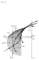
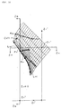
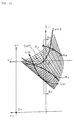
- Fig. 35 and Fig. 36 show an effective surface of action (Fig. 35) drawn by the pinion involute helicoidal tooth surface D determined in such a way as described above and a generated gear conjugate tooth surface D (Fig. 36).
- R 1h designates the radius of the face cylinder of pinion.
- the path of contact on which the contact ratio of the tooth surface D becomes maximum is located on the large end side far from the g 0D , and the value thereof is about 2.1. Consequently, the tooth bearing of the tooth surface D must be formed on the large end side along the path of contact on which the contact ratio becomes maximum.
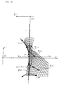
- Fig. 37 and Fig. 38 show an effective surface of action (Fig. 27) drawn by the pinion tooth surface C c and a generated gear conjugate tooth surface C c (Fig. 38). It is known that the effective surface of action and the large gear conjugate tooth surface C c are realized within the zone (R 2t -R 2h ) of the large gear given by the selected pinion tooth surface C c . The contact ratio along the path of contact is 0.9. Consequently, the tooth bearing of the tooth surface C c cannot but be formed on the small end side for the use of the lengthwise engagement. In the tooth surface C c , the conditions of the fluctuation of a bearing load being zero is not satisfied.
- a sharpened top is generated on the large end side of a large gear in a combination of a cylinder pinion and adiskgear.
- the top land becomes somewhat narrower to the large end, but a top land that is substantially allowable for practical use is realized. This fact is based on the following reason.
- the paths of contact g 0D , g 0C are both located at the vicinity of the limiting path g 2z , and incline to the g 2z in the reverse directions mutually. Consequently, the base cylinder radii R b20D , R b20C of the g 0D and the g 0C on the gear side are near to the base cylinder radius R b2z of the g 2z , and the difference between them is small. Then, by modification of the tooth surface C to the tooth surface C c (point P 0C is changed to the point P 0CC ), the difference becomes still smaller as a result.
- the ⁇ b10 is large, and the changes of the inclination angle ⁇ 2m of the path of contact is small as shown in Figs. 28-30. Consequently, the changes of the ⁇ b2m becomes further smaller from the expressions (92).
- the large gear tooth surfaces D, C c can be considered as involute helicoids having base cylinders R b20D and R b20C whose cross sections of rotation are approximate involute curves. Because the difference between R b20D and R b20C is small, the two approximate involute curves are almost parallel with each other, and the top land of the large gear is almost constant from the small end to the large end.
- a computer support design system shown in Fig. 40 performs design support.
- the CAD system is provided with a computer 3 including a processor 1 and a memory 2, an input unit 4, an output unit 5 and an external memory 6.
- a gear design program for implementing the gear design method mentioned above is recorded in the recording medium in advance. As the occasion demands, the program is read out from the recording medium to be executed by the computer 3.
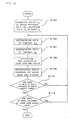
- Fig. 41 shows the outline of the operation flow.
- the radius R 20 of the design reference point P 0 and the inclination angle ⁇ 0 of the plane S n are determined on the basis of requirement values of the design of a hypoid gear (S100).
- the normal (path of contact) g 0D of the tooth surface D passing at the design reference point P 0 is determined from the limiting path g 2z (S102).
- the normal (path of contact) g 0C of the tooth surface C passing at the design reference point P 0 is determined (S104).
- the face surface of the gear and the face surface of the pinion are determined on the basis of the paths of contact g 0D , g 0C (S106).
- One of either the pinion side or the large gear side of the involute helicoid having the paths of contact g 0D , g 0C as its tooth surface normal is given, and the other side is then determined (S108).
- Whether the formed tooth surfaces C, D of the pinion have almost the same leads or not is then judged (S110). If the tooth surfaces C, D do not have almost the same leads, the system returns to the step S102 and obtains the path of contact again.
- Table 1 shows an example of calculated specifications of a hypoid gear.
Landscapes
- Engineering & Computer Science (AREA)
- General Engineering & Computer Science (AREA)
- Mechanical Engineering (AREA)
- Gears, Cams (AREA)
Abstract
Description



- 2: a rotation angle of the gear II;
- q2c(0), z2c(0): q2c and z2c coordinates of the point of contact when the 2 is zero;
- χ20: the inclination angle of the plane of action G20 of the gear II;
- ψb20: the inclination angle of the g0 on the plane of action G20; and
- Rb20: the radius of a base cylinder being tangent with the plane of action G20.
| shaft angle Σ | 90° |
| gear ratio i0 | 4.1 |
| instantaneous axis angle Γs | 76.29° |
| offset E | 35mm under the center positions of axes I and II to instantaneous axis |
| vcs1 | -1.965mm |
| vcs2 | 33.035mm |
| large end radius of gear R2h | 95mm |
| small end radius of gear R2t | 67mm |

- 22p: the angular pitch of the large gear.


Claims (12)
- A method for designing a hypoid gear consisting of a pair of gears including a pinion and a large gear, either of said gears being a first gear having an involute helicoid as a tooth surface, the other of said gears being a second gear having a tooth surface conjugate to the former tooth surface, said method comprising the steps of:assigning to said gears (a) a stationary coordinate system in which one of three mutually orthogonal coordinate axes coincides with a rotation axis of the gear and one of other two coordinate axes coincides with a common perpendicular for the rotation axis of the gear and a rotation axis of a mating gear to be engaged with the gear, (b) a rotary coordinate system in which one of three mutually orthogonal coordinate axes coincides with the axis of said stationary coordinate system that coincides with the rotation axis of the gear among the three coordinate axes of said stationary coordinate system, said rotary coordinate system rotating about the coincided coordinate axis together with the gear, the other two coordinate axes of the three orthogonal axes coinciding with the other two axes of said stationary coordinate system respectively when a rotation angle of the gear is zero, and (c) a parameter coordinate system in which said stationary coordinate system is rotated and transformed about the rotation axis of the gear so that one of the other two coordinate axes of said stationary coordinate system becomes parallel with the plane of action of the gear, respectively;describing a path of contact of a pair of tooth surfaces of the gear and the mating gear which engage with each other during the rotation of the gears and an inclination angle of a common normal which is a normal at each point of contact for the pair of tooth surfaces respectively in terms of a first function, in which a rotation angle of the gear is used as a parameter, in said parameter coordinate system;describing the path of contact and the inclination angle of the common normal respectively in terms of a second function, in which a rotation angle of the gear is used as a parameter, based on the first function and a relationship between relative positions of said stationary coordinate system and said parameter coordinate system, in said stationary coordinate system;acquiring the path of contact and the inclination angle of the common normal in the stationary coordinate system, respectively, and acquiring a tooth profile by describing the path of contact and the inclination angle of the common normal, respectively, in terms of a third function, in which the rotation angle of the gear is used as a parameter, based on the second function and the relationship between the relative positions of said rotary coordinate system and said stationary coordinate system, in said rotary coordinate system;acquiring a surface of action for the pair of tooth surfaces having the tooth profile;acquiring action limit curves which are orthogonal projections of axes of the two gears on the surface of action, and acquiring a tip line of the second gear in the surface of action, based on the tooth surface of the second gear, and further acquiring an effective surface of action existing between the action limit curves and the tip line; andjudging whether or note the effective surface of action exists over a whole facewidth of the gear.
- A hypoid gear design method according to claim 1, said method further comprising the step of:acquiring an angle between paths of contact for the tooth surface of a drive side of the first gear and the tooth surface of a coast side of the first gear such that the teeth of the first gear have an appropriate strength.
- A hypoid gear design method according to claim 2, said method further comprising the steps of:acquiring specifications of an equivalent rack including a tooth surface based on the path of contact of the respective tooth surfaces of the drive side and the coast side; andacquiring a distance of the respective tip lines of the tooth surface of the drive side and the tooth surface of the coast side of the second gear, based on the specifications of the equivalent rack, and judging whether the acquired distance is equal to or greater than a predetermined value.
- A hypoid gear design method according to claim 1, wherein at the acquiring of the pair of tooth surfaces a design reference point is set near a center of the face width of the gear, and
when the effective surface of action is insufficient at a small end side of the face width of the gear, the design reference point is shifted toward the small end side of the face width of the gear, and the effective surface of action is acquired again. - A hypoid gear design method according to claim 3, wherein at the acquiring of the pair of tooth surfaces a design reference point is set near a center of the face width of the gear, and
when the distance of the tip line is insufficient at a large end side, the design reference point is shifted toward the large end side of the face width of the gear, and the effective surface of action is acquired again. - A hypoid gear design method according to claim 3, wherein at the acquiring of the pair of tooth surfaces a design reference point is set near a center of the face width of the gear, and
when the effective surface of action is insufficient at a small end side of the face width of the gear and the distance of the tip line is insufficient at a large end side, the face width of the gear is reduced. - A program for executing a hypoid gear design method according to any one of claims 1-6 with a computer.
- A hypoid gear in which a tooth surface of one gear of a pair of gears is an involute helicoid, wherein, in said hypoid gear, a radius of a base circle of the gear having the involute helicoidal tooth surface differs at a drive side and a coast side.
- A hypoid gear according to claim 8, wherein leads of tooth surfaces on the drive side and the coast side of the gear provided with the involute helicoid are almost the same.
- A hypoid gear according to claim 8, wherein a ratio of an offset E being the shortest distance between each axis of a pinion and a gear constituting said hypoid gear and a radius R20 at a design point of the gear (E/R20) is larger than 0.25.
- A hypoid gear according to claim 8, a gear ratio i0 thereof is within a range of 2.5 to 5.
- A hypoid gear according to claim 8, wherein a helical angle ψ0 thereof is within a range of 35° to 70°.
Applications Claiming Priority (3)
| Application Number | Priority Date | Filing Date | Title |
|---|---|---|---|
| JP2000054886 | 2000-02-29 | ||
| JP2000054886 | 2000-02-29 | ||
| PCT/JP2001/001450 WO2001065148A1 (en) | 2000-02-29 | 2001-02-27 | Hypoid gear design method |
Publications (3)
| Publication Number | Publication Date |
|---|---|
| EP1260736A1 true EP1260736A1 (en) | 2002-11-27 |
| EP1260736A4 EP1260736A4 (en) | 2004-03-17 |
| EP1260736B1 EP1260736B1 (en) | 2005-09-07 |
Family
ID=18576084
Family Applications (1)
| Application Number | Title | Priority Date | Filing Date |
|---|---|---|---|
| EP01906338A Expired - Lifetime EP1260736B1 (en) | 2000-02-29 | 2001-02-27 | Hypoid gear design method |
Country Status (4)
| Country | Link |
|---|---|
| EP (1) | EP1260736B1 (en) |
| JP (1) | JP3733908B2 (en) |
| DE (1) | DE60113239T2 (en) |
| WO (1) | WO2001065148A1 (en) |
Cited By (4)
| Publication number | Priority date | Publication date | Assignee | Title |
|---|---|---|---|---|
| WO2010008096A1 (en) * | 2008-07-18 | 2010-01-21 | Kabushiki Kaisha Toyota Chuo Kenkyusho | Hypoid gear design method and hypoid gear |
| US7707879B2 (en) | 2005-04-15 | 2010-05-04 | Fuji Jukogyo Kabushiki Kaisha | Gear pair evaluation apparatus, gear pair evaluation program, and gear pair whose tooth surfaces are evaluated using the apparatus and program |
| WO2010068412A1 (en) * | 2008-11-25 | 2010-06-17 | The Gleason Works | Hypoid gears with low shaft angles |
| CN104121350A (en) * | 2014-05-16 | 2014-10-29 | 清华大学 | Hypoid gear bending geometric coefficient setting method |
Families Citing this family (5)
| Publication number | Priority date | Publication date | Assignee | Title |
|---|---|---|---|---|
| JP6220264B2 (en) * | 2013-12-24 | 2017-10-25 | 株式会社Subaru | Final reduction gear |
| CN110889194B (en) * | 2019-10-28 | 2023-06-06 | 南京高精齿轮集团有限公司 | Modeling method for NX involute deflection helical gear |
| CN113111463B (en) * | 2021-04-21 | 2024-04-19 | 华中科技大学 | Cycloid gear tooth profile design method |
| CN113419488B (en) * | 2021-06-08 | 2022-07-08 | 湖北工业大学 | A method for eliminating overcutting of non-circular tooth sector deformation and modification |
| CN116275302B (en) * | 2023-02-27 | 2025-08-01 | 天津理工大学 | Design method of rake face of multi-head double-conical-surface secondary enveloping ring surface worm gear hob |
Family Cites Families (7)
| Publication number | Priority date | Publication date | Assignee | Title |
|---|---|---|---|---|
| FR1230462A (en) * | 1957-10-01 | 1960-09-15 | ||
| JP3102204B2 (en) * | 1993-05-31 | 2000-10-23 | 日産自動車株式会社 | Tooth profile structure of spiral bevel gear |
| JPH07208582A (en) * | 1994-01-26 | 1995-08-11 | Nissan Motor Co Ltd | Spiral tooth bevel gear pinion |
| JPH0828659A (en) * | 1994-07-22 | 1996-02-02 | Shigeyoshi Osada | Line contact crossed helical gear |
| JP3484879B2 (en) | 1995-06-05 | 2004-01-06 | 株式会社豊田中央研究所 | Gear design method, gear and gear measurement method |
| JP3543431B2 (en) * | 1995-07-17 | 2004-07-14 | 日産自動車株式会社 | Bevel gear tooth profile design method |
| JPH10331957A (en) * | 1997-05-30 | 1998-12-15 | Toyota Central Res & Dev Lab Inc | Gear pair and tooth surface shape setting method |
-
2001
- 2001-02-27 JP JP2001563814A patent/JP3733908B2/en not_active Expired - Lifetime
- 2001-02-27 DE DE60113239T patent/DE60113239T2/en not_active Expired - Lifetime
- 2001-02-27 WO PCT/JP2001/001450 patent/WO2001065148A1/en not_active Ceased
- 2001-02-27 EP EP01906338A patent/EP1260736B1/en not_active Expired - Lifetime
Cited By (14)
| Publication number | Priority date | Publication date | Assignee | Title |
|---|---|---|---|---|
| US7707879B2 (en) | 2005-04-15 | 2010-05-04 | Fuji Jukogyo Kabushiki Kaisha | Gear pair evaluation apparatus, gear pair evaluation program, and gear pair whose tooth surfaces are evaluated using the apparatus and program |
| EP2514995A3 (en) * | 2008-07-18 | 2013-04-24 | Kabushiki Kaisha Toyota Chuo Kenkyusho | Hypoid gear design method and hypoid gear |
| CN102099598A (en) * | 2008-07-18 | 2011-06-15 | 株式会社丰田中央研究所 | Hypoid gear design method and hypoid gear |
| EP2514995A2 (en) | 2008-07-18 | 2012-10-24 | Kabushiki Kaisha Toyota Chuo Kenkyusho | Hypoid gear design method and hypoid gear |
| WO2010008096A1 (en) * | 2008-07-18 | 2010-01-21 | Kabushiki Kaisha Toyota Chuo Kenkyusho | Hypoid gear design method and hypoid gear |
| CN102099598B (en) * | 2008-07-18 | 2013-12-25 | 株式会社丰田中央研究所 | Hypoid gear design method and hypoid gear |
| US8881401B2 (en) | 2008-07-18 | 2014-11-11 | Kabushiki Kaisha Toyota Chuo Kenkysho | Hypoid gear design method and hypoid gear |
| US10578192B2 (en) | 2008-07-18 | 2020-03-03 | Kabushiki Kaisha Toyota Chuo Kenkyusho | Hypoid gear design method and hypoid gear |
| WO2010068412A1 (en) * | 2008-11-25 | 2010-06-17 | The Gleason Works | Hypoid gears with low shaft angles |
| CN102224360A (en) * | 2008-11-25 | 2011-10-19 | 格里森工场 | Hypoid gears with low shaft angles |
| US8573087B2 (en) | 2008-11-25 | 2013-11-05 | The Gleason Works | Hypoid gears with low shaft angles |
| CN102224360B (en) * | 2008-11-25 | 2014-04-02 | 格里森工场 | Hypoid gears with low shaft angles |
| CN104121350A (en) * | 2014-05-16 | 2014-10-29 | 清华大学 | Hypoid gear bending geometric coefficient setting method |
| CN104121350B (en) * | 2014-05-16 | 2016-06-15 | 清华大学 | A kind of method to set up of hypoid gear bending geometrical factor |
Also Published As
| Publication number | Publication date |
|---|---|
| JP3733908B2 (en) | 2006-01-11 |
| DE60113239D1 (en) | 2005-10-13 |
| WO2001065148A1 (en) | 2001-09-07 |
| DE60113239T2 (en) | 2006-06-29 |
| EP1260736B1 (en) | 2005-09-07 |
| EP1260736A4 (en) | 2004-03-17 |
Similar Documents
| Publication | Publication Date | Title |
|---|---|---|
| US7665380B2 (en) | Hypoid gear design method | |
| US8967012B2 (en) | Double involute pinion-face gear drive system | |
| JP3484879B2 (en) | Gear design method, gear and gear measurement method | |
| JP4355451B2 (en) | Gear finishing method and gear | |
| CN1007449B (en) | Face gear transmissons | |
| EP1260736B1 (en) | Hypoid gear design method | |
| WO2011093744A1 (en) | Eccentrically cycloidal engagement of toothed profiles having curved teeth | |
| CN103270344A (en) | Load-carrying optimized bevel gear toothing | |
| US3881364A (en) | Low noise gearing | |
| US6205879B1 (en) | Helical and spur gear drive with double crowned pinion tooth surfaces and conjugated gear tooth surfaces | |
| Zheng et al. | Investigation on the wear of spur gears generated by modified cutter | |
| CN101725690A (en) | Discrete tooth harmonic transmission | |
| US20240401685A1 (en) | Herringbone Gear Pair With Constant Meshing Characteristics Constructed Tooth Pair | |
| Buckingham | Spur gears: design, operation, and production | |
| Vullo | Gears: General Concepts, Definitions and Some Basic Quantities | |
| Bo¨ rner et al. | Development of conical involute gears (beveloids) for vehicle transmissions | |
| Song et al. | Loaded tooth contact analysis of intersected beveloid and cylindrical involute gear pair with small shaft angle | |
| JPWO2001065148A1 (en) | How to design a hypoid gear | |
| Volkov et al. | Grinding of the inner thread without tilt of the tool spindle | |
| Park et al. | The spherical involute bevel gear: its geometry, kinematic behavior and standardization | |
| Vullo | The geometry of involute spur gears | |
| US4794811A (en) | Helical gearsets | |
| Ye et al. | Loaded tooth contact analysis of power-split gear drives considering shaft deformation and assembly errors | |
| Suzuki et al. | Design of high-reduction hypoid gears meshing in plane of action | |
| Hlebanja et al. | Optimization of Planocentric Gear Train Characteristics with CA-Tools |
Legal Events
| Date | Code | Title | Description |
|---|---|---|---|
| PUAI | Public reference made under article 153(3) epc to a published international application that has entered the european phase |
Free format text: ORIGINAL CODE: 0009012 |
|
| 17P | Request for examination filed |
Effective date: 20020827 |
|
| AK | Designated contracting states |
Kind code of ref document: A1 Designated state(s): AT BE CH CY DE DK ES FI FR GB GR IE IT LI LU MC NL PT SE TR |
|
| A4 | Supplementary search report drawn up and despatched |
Effective date: 20040203 |
|
| RIC1 | Information provided on ipc code assigned before grant |
Ipc: 7F 16H 55/08 B Ipc: 7F 16H 55/22 A |
|
| RBV | Designated contracting states (corrected) |
Designated state(s): DE FR GB |
|
| 17Q | First examination report despatched |
Effective date: 20040708 |
|
| GRAP | Despatch of communication of intention to grant a patent |
Free format text: ORIGINAL CODE: EPIDOSNIGR1 |
|
| GRAS | Grant fee paid |
Free format text: ORIGINAL CODE: EPIDOSNIGR3 |
|
| GRAA | (expected) grant |
Free format text: ORIGINAL CODE: 0009210 |
|
| AK | Designated contracting states |
Kind code of ref document: B1 Designated state(s): DE FR GB |
|
| REG | Reference to a national code |
Ref country code: GB Ref legal event code: FG4D |
|
| REF | Corresponds to: |
Ref document number: 60113239 Country of ref document: DE Date of ref document: 20051013 Kind code of ref document: P |
|
| ET | Fr: translation filed | ||
| PLBE | No opposition filed within time limit |
Free format text: ORIGINAL CODE: 0009261 |
|
| STAA | Information on the status of an ep patent application or granted ep patent |
Free format text: STATUS: NO OPPOSITION FILED WITHIN TIME LIMIT |
|
| 26N | No opposition filed |
Effective date: 20060608 |
|
| REG | Reference to a national code |
Ref country code: FR Ref legal event code: PLFP Year of fee payment: 16 |
|
| REG | Reference to a national code |
Ref country code: FR Ref legal event code: PLFP Year of fee payment: 17 |
|
| REG | Reference to a national code |
Ref country code: FR Ref legal event code: PLFP Year of fee payment: 18 |
|
| PGFP | Annual fee paid to national office [announced via postgrant information from national office to epo] |
Ref country code: GB Payment date: 20180221 Year of fee payment: 18 Ref country code: DE Payment date: 20180214 Year of fee payment: 18 |
|
| PGFP | Annual fee paid to national office [announced via postgrant information from national office to epo] |
Ref country code: FR Payment date: 20180111 Year of fee payment: 18 |
|
| REG | Reference to a national code |
Ref country code: DE Ref legal event code: R119 Ref document number: 60113239 Country of ref document: DE |
|
| GBPC | Gb: european patent ceased through non-payment of renewal fee |
Effective date: 20190227 |
|
| PG25 | Lapsed in a contracting state [announced via postgrant information from national office to epo] |
Ref country code: DE Free format text: LAPSE BECAUSE OF NON-PAYMENT OF DUE FEES Effective date: 20190903 Ref country code: GB Free format text: LAPSE BECAUSE OF NON-PAYMENT OF DUE FEES Effective date: 20190227 |
|
| PG25 | Lapsed in a contracting state [announced via postgrant information from national office to epo] |
Ref country code: FR Free format text: LAPSE BECAUSE OF NON-PAYMENT OF DUE FEES Effective date: 20190228 |