EP1260722A2 - Linear motion guide bearing device and ball screw device - Google Patents
Linear motion guide bearing device and ball screw device Download PDFInfo
- Publication number
- EP1260722A2 EP1260722A2 EP02010843A EP02010843A EP1260722A2 EP 1260722 A2 EP1260722 A2 EP 1260722A2 EP 02010843 A EP02010843 A EP 02010843A EP 02010843 A EP02010843 A EP 02010843A EP 1260722 A2 EP1260722 A2 EP 1260722A2
- Authority
- EP
- European Patent Office
- Prior art keywords
- retainer
- retainer pieces
- pieces
- rolling elements
- rolling
- Prior art date
- Legal status (The legal status is an assumption and is not a legal conclusion. Google has not performed a legal analysis and makes no representation as to the accuracy of the status listed.)
- Granted
Links
Images




Classifications
-
- F—MECHANICAL ENGINEERING; LIGHTING; HEATING; WEAPONS; BLASTING
- F16—ENGINEERING ELEMENTS AND UNITS; GENERAL MEASURES FOR PRODUCING AND MAINTAINING EFFECTIVE FUNCTIONING OF MACHINES OR INSTALLATIONS; THERMAL INSULATION IN GENERAL
- F16C—SHAFTS; FLEXIBLE SHAFTS; ELEMENTS OR CRANKSHAFT MECHANISMS; ROTARY BODIES OTHER THAN GEARING ELEMENTS; BEARINGS
- F16C29/00—Bearings for parts moving only linearly
- F16C29/04—Ball or roller bearings
- F16C29/06—Ball or roller bearings in which the rolling bodies circulate partly without carrying load
- F16C29/0633—Ball or roller bearings in which the rolling bodies circulate partly without carrying load with a bearing body defining a U-shaped carriage, i.e. surrounding a guide rail or track on three sides
- F16C29/0635—Ball or roller bearings in which the rolling bodies circulate partly without carrying load with a bearing body defining a U-shaped carriage, i.e. surrounding a guide rail or track on three sides whereby the return paths are provided as bores in a main body of the U-shaped carriage, e.g. the main body of the U-shaped carriage is a single part with end caps provided at each end
- F16C29/0638—Ball or roller bearings in which the rolling bodies circulate partly without carrying load with a bearing body defining a U-shaped carriage, i.e. surrounding a guide rail or track on three sides whereby the return paths are provided as bores in a main body of the U-shaped carriage, e.g. the main body of the U-shaped carriage is a single part with end caps provided at each end with balls
- F16C29/0642—Ball or roller bearings in which the rolling bodies circulate partly without carrying load with a bearing body defining a U-shaped carriage, i.e. surrounding a guide rail or track on three sides whereby the return paths are provided as bores in a main body of the U-shaped carriage, e.g. the main body of the U-shaped carriage is a single part with end caps provided at each end with balls with four rows of balls
-
- F—MECHANICAL ENGINEERING; LIGHTING; HEATING; WEAPONS; BLASTING
- F16—ENGINEERING ELEMENTS AND UNITS; GENERAL MEASURES FOR PRODUCING AND MAINTAINING EFFECTIVE FUNCTIONING OF MACHINES OR INSTALLATIONS; THERMAL INSULATION IN GENERAL
- F16C—SHAFTS; FLEXIBLE SHAFTS; ELEMENTS OR CRANKSHAFT MECHANISMS; ROTARY BODIES OTHER THAN GEARING ELEMENTS; BEARINGS
- F16C33/00—Parts of bearings; Special methods for making bearings or parts thereof
- F16C33/30—Parts of ball or roller bearings
- F16C33/37—Loose spacing bodies
- F16C33/3706—Loose spacing bodies with concave surfaces conforming to the shape of the rolling elements, e.g. the spacing bodies are in sliding contact with the rolling elements
-
- F—MECHANICAL ENGINEERING; LIGHTING; HEATING; WEAPONS; BLASTING
- F16—ENGINEERING ELEMENTS AND UNITS; GENERAL MEASURES FOR PRODUCING AND MAINTAINING EFFECTIVE FUNCTIONING OF MACHINES OR INSTALLATIONS; THERMAL INSULATION IN GENERAL
- F16H—GEARING
- F16H25/00—Gearings comprising primarily only cams, cam-followers and screw-and-nut mechanisms
- F16H25/18—Gearings comprising primarily only cams, cam-followers and screw-and-nut mechanisms for conveying or interconverting oscillating or reciprocating motions
- F16H25/20—Screw mechanisms
- F16H25/22—Screw mechanisms with balls, rollers, or similar members between the co-operating parts; Elements essential to the use of such members
- F16H25/2204—Screw mechanisms with balls, rollers, or similar members between the co-operating parts; Elements essential to the use of such members with balls
- F16H25/2233—Screw mechanisms with balls, rollers, or similar members between the co-operating parts; Elements essential to the use of such members with balls with cages or means to hold the balls in position
- F16H25/2238—Screw mechanisms with balls, rollers, or similar members between the co-operating parts; Elements essential to the use of such members with balls with cages or means to hold the balls in position using ball spacers, i.e. spacers separating the balls, e.g. by forming a chain supporting the balls
-
- F—MECHANICAL ENGINEERING; LIGHTING; HEATING; WEAPONS; BLASTING
- F16—ENGINEERING ELEMENTS AND UNITS; GENERAL MEASURES FOR PRODUCING AND MAINTAINING EFFECTIVE FUNCTIONING OF MACHINES OR INSTALLATIONS; THERMAL INSULATION IN GENERAL
- F16C—SHAFTS; FLEXIBLE SHAFTS; ELEMENTS OR CRANKSHAFT MECHANISMS; ROTARY BODIES OTHER THAN GEARING ELEMENTS; BEARINGS
- F16C2240/00—Specified values or numerical ranges of parameters; Relations between them
- F16C2240/40—Linear dimensions, e.g. length, radius, thickness, gap
-
- Y—GENERAL TAGGING OF NEW TECHNOLOGICAL DEVELOPMENTS; GENERAL TAGGING OF CROSS-SECTIONAL TECHNOLOGIES SPANNING OVER SEVERAL SECTIONS OF THE IPC; TECHNICAL SUBJECTS COVERED BY FORMER USPC CROSS-REFERENCE ART COLLECTIONS [XRACs] AND DIGESTS
- Y10—TECHNICAL SUBJECTS COVERED BY FORMER USPC
- Y10T—TECHNICAL SUBJECTS COVERED BY FORMER US CLASSIFICATION
- Y10T74/00—Machine element or mechanism
- Y10T74/19—Gearing
- Y10T74/19642—Directly cooperating gears
- Y10T74/19698—Spiral
- Y10T74/19702—Screw and nut
- Y10T74/19744—Rolling element engaging thread
- Y10T74/19749—Recirculating rolling elements
- Y10T74/19777—Interconnected or cooperating rollers or roller structure
Definitions
- the present invention relates to a linear motion device used in, for example, the machine tool. More particularly, the present invention relates to a linear motion guide bearing device in which retainer pieces are each interposed.between adjacent rolling elements which circulatingly roll in the longitudinal direction of a guide rail. In addition, the present invention relates to a ball screw device in which retainer pieces are each interposed between adjacent rolling elements which circulatingly roll along an element rolling groove, spirally shaped, defined by a thread groove of a ball screw shaft and a thread groove of a nut.
- the present invention relates to retainer pieces each disposedbetween adjacent balls in order to secure good operation of a ball screw.
- the term "the thickness of the retainer piece” or the “thickness” on the retainer piece does not means the thickness of the whole retainer piece, but means the thickness of the retainer piece to separate the surface of a ball from the surface of another ball adjacent to the former.
- the "thickness" on the retainer piece means that the thickness of the retainer piece at a position with respect to a position defined a line connected centers of adjacent rolling elements, when two rolling elements are arranged on a collinear.
- a linear motion guide bearing device 10 as shown in Fig. 9 is known for a device for linearly guiding a work table of, for example, a machine tool.
- the linear motion guide bearing device 10 is provided with a guide rail 11 being rectangular in cross section.
- Rolling grooves 12 for the rolling elements are formed on both side surfaces of the guide rail 11, and from one end to the other end of the guide rail 11.
- a plurality of spherical rolling elements 13 are engaged with each other in the rolling grooves 12. When the rolling elements 13 roll along the rolling element grooves 12, a slider 14 is relatively moved in the longitudinal direction of the guide rail 11.
- the slider 14 have a slider body 15 straddling the guide rail 11, and end caps 16 provided at the front end and the rear end of the slider body 15.
- Rolling grooves 17 for the rolling elements are arcuate in cross section and are formed in the inner side walls of the each of sleeves 15a of the slider body 15 of the slider 14, respectively.
- the spherical rolling elements 13 roll in and along a rolling-element passage which is formed between the rolling grooves 17 and the rolling grooves 12.
- a passage hole for the rolling elements 18 is provided within each of the sleeves 15a of the slider body 15 and extends parallel to the rolling grooves 17.
- the rolling grooves 17 and the passage holes 18 form an endless circulating raceway 20 of the rolling elements 13 together with rolling-element return passages 19 formed in the end caps 16.
- the retainer pieces which are each interposed between adjacent rolling elements in the rolling element series, are all different in their pieces having different thicknesses must be prepared. This brings about cost increase in the manufacturing of the retainer pieces and assembling of them into between the adjacent rolling elements.
- balls(rolling elements) are arranged in the ball screw to support a load. Those balls roll in a circulating manner, and through the ball rolling, a good rotation-to-linear motion conversion is secured while maintaining load capacity and rigidity. Since the rolling of the balls occurs randomly, sometimes adjacent balls act to mutually impart compression forces to each other, and the slipping state often occurs. As a result, the balls exhibit great resistance to impede the rolling of other balls, so that a torque variation occurs and causes operation trouble.
- a ball screw which, to solve such a problem, retainer pieces are each disposed between adjacent balls, and resistance acting to impede the rolling of other balls is not generated by avoiding the mutual ball contact.
- the balls are arranged at substantially regular spatial intervals by use of the retainer pieces, and the following new problems arise.
- an object of the present invention is to provide a linear motion device such as a linear motion guide bearing device and a ball screw, which reduce the vibrations and noises, which are ascribed to the periodical passing vibration of rolling elements, without increasing the manufacturing cost.
- a first aspect of the present invention provides a linear motion guide bearing device comprising: a guide rail having rolling grooves extending in an axial direction of the linear motion guide bearing device and formed on the outer surface thereof; a slider engaged with the guide rail so as to move in the axial direction of the guide rail; a plurality of rolling elements interposed between the slider and the rolling grooves of the guide rail; and a plurality of retainer pieces each interposed between adjacent rolling elements, the retainer pieces including a plurality kinds of retainer pieces having different thicknesses, and the number of kinds of the retainer pieces is smaller than the number of the rolling elements of the rolling element series.
- a second aspect of the present invention provides a ball screw device comprising: a screw shaft having a first thread groove spirally formed in an outer peripheral surface thereof; a nut having a second thread groove in the inner peripheral surface thereof and being fitted to the screw shaft, the second thread groove corresponding to the first thread groove of the screw shaft; a plurality of rolling elements rollably received in a space defined between the first and second thread grooves; a circulating member fixed to the nut so as to form a circulating passage through which the rolling elements rolling along the space defined between the first and second thread grooves endlessly circulate; and a plurality of retainer pieces each interposed between adjacent rolling elements, the retainer pieces including a plurality kinds of retainer pieces having different thicknesses, and the number of kinds of the retainer pieces are smaller than the number of the rolling elements of the rolling element series.
- the linear motion device is capable of reducing the vibrations and noises, which are ascribed to the periodical passing vibration of the rolling elements, without increasing the cost.
- the retainer pieces are two to five number of kinds of retainer pieces. If the number of retainer pieces is so selected, the retainer pieces preparation is well balanced with the retainer pieces assembling.
- the rolling element series is formed using different kinds of retainer pieces having different thicknesses, it is preferable that every kinds of retainer pieces having different thicknesses are sorted by colors, and each retainer piece has an identifying mark every kind of retainer piece.
- the significant difference of the element-to-element pitches is preferably 1% to 10% of the diameter of the rolling element.
- the retainer pieces have each an elastic structure or are each made of elastic material.
- a method of controlling a distance of the center-to-center distance between the adjacent balls or the number of the balls by making different the thicknesses of the retainer pieces each located between the adjacent balls.
- FIG. 1 A first embodiment of a linear motion guide bearing device according to the present invention is shown in Fig. 1.
- reference numerals 21A, 21B, 21C, and 21D indicate retainer pieces each located between adjacent rolling elements 13. Those retainer pieces 21A to 21D are designed such that their thicknesses T A , T B , T C , and T D each measured between adjacent rolling elements are different as follows: T A > T B > T C > T D .
- pitches among rolling elements of a rolling element series 22 consisting of the retainer pieces 21A to 21D and the rolling elements 13 are given by A > B > C > D where A is a distance measured between two spherical rolling elements 13, inclusive of the retainer piece 21A, B is a distance measured between two spherical rolling elements 13, inclusive of the retainer piece 21B, C is a distance measured between two spherical rolling elements 13, inclusive of the retainer piece 21C, and D is a distance measured between two spherical rolling elements 13, inclusive of the retainer piece 21D.
- retainer pieces 21A to 21D are colored every kind of retainer piece: for example, the retainer piece 21A is colored red; the retainer piece 21B is coloredblue; the retainer piece 21C is colored yellow; and the retainer piece 21D is colored white.
- marks ⁇ indicate noise levels in the case where the rolling element series consists of four kinds of retainer pieces 21A to 21D
- marks ⁇ indicate noise levels in the case where the rolling element series consists of one kind of retainer pieces.
- the abscissa represents a feeding speed (m/s) of the slider, and the ordinate represents noise levels (dB).
- the noise level is lower than the noise level in the case where the rolling element series consists of one kind of retainer pieces.
- the reason for this maybe considered as follows. Where four kinds of retainer pieces 21A to 21D having different thicknesses T A , T B , T C , and T D are used, the element-to-element pitches of the rolling element series 22 are not uniform. As a result, the periodical passing vibration of the rolling element having due to rolling motion of the rolling elements 13, is reduced.
- the vibration and noise, which are ascribed to the periodical passing vibration of the rolling elements maybe reducedwithout making all the element-to-element pitches of the rolling element series different. Therefore, there is no need of using many kinds of retainer pieces having different element-to-element thicknesses. Accordingly, the periodical passing vibration due to rolling motion of the spherical rolling elements is reduced.
- the retainer pieces 21A to 21D are sorted by different colors every kind of retainer pieces. Accordingly, the retainer pieces having different thicknesses may readily be discriminated. It is prevented that the retainer pieces are each assembled to between adjacent rolling elements erroneously. The management and discrimination of the retainer pieces are easy.
- the rolling element series is formed by assembling each of individual retainer pieces to between adjacent rolling elements.
- a series of rolling elements formed by connected retainer pieces each other one after another may be used to form the rolling element series.
- the rolling element series 22 is formed by assembling the four kinds of retainer pieces 21A to 21D to between adjacent spherical rolling elements 13 regularly. If required, the four kinds of retainer pieces 21A to 21D may be assembled to between adjacent rolling elements 13 irregularly, for the same purpose. In this way, the periodical passing vibration of the rolling elements due to rolling motion of the rolling elements, is further reduced.
- the rolling element series 22 is formed by using four kinds of retainer pieces 21A to 21D which are substantially equal in number.
- the rolling element series 22 may also be formed by using those kinds of retainer pieces which are different in number, for example, two pieces of retainer pieces 21A, four pieces of retainer pieces 21b, eight pieces of retainer pieces 21C, and eight pieces of retainer pieces 21D.
- the retainer pieces 21A to 21D are sorted by colors. Those retainer pieces 21A to 21D may be marked with colored identifying marks, respectively. The identifying marks may be symbols and so on. The following method may be used for assembling the retainer pieces to between the rolling elements.
- the numbers of those kinds of retainer pieces necessary for forming one rolling element series are extracted (e.g., X 1 is a plurality of retainer pieces 21A, X 2 is a plurality of retainer pieces 21B, X 3 is a plurality of retainer pieces 21C, and X 4 number of retainer pieces 21D), and then those are put in a container and agitated to thereby array retainer pieces randomly.
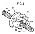
- a ball screw device as one form of a screw device is shown in Fig. 4.
- a ball nut 46 having a spiral thread groove 44 formed in the inner peripheral surface thereof is loosely fit to a screw shaft 43 having a spiral thread groove 42 in the outer peripheral surface thereof and extending in the axial direction.
- the spiral thread groove 44 of the ball nut 46 are disposed facing the thread groove 42 of the screw shaft 43 so as to form a spiral passage therebetween.
- a plurality of balls 45 as rolling elements are rollably put in the spiral passage.
- the ball. nut 46 linearly moves through the rolling of the balls 45 by rotation of the screw shaft 43.
- the ball nut 46 linearly moves while the balls 45 roll along the circulating passage formed by both of the thread grooves 42 and 44. To continuously move the ball nut 46, it is necessary to circulate the balls 45 endlessly.
- a part of the outer peripheral surface of the ball nut 46 is flattened, and a couple of holes 51 communicating with both the thread screws 42 and 44 are formed in the flat part of the ball nut 46 so as to straddle the screw shaft 43.
- Both ends of a U-shaped ball tube 50A as a ball circulating member are fit into the holes 51, thereby forming a ball circulating passage 52.
- Circulation piece, end cap and others may be used for forming the circulating path, in addition to the ball tube.
- retainer pieces 40 are each interposed between adjacent balls 45 of a plurality of balls 45.
- the number of balls 45 are rollably put in a spiral passage defined between a thread groove 44 of a ball nut 46 and a thread groove 42 of a screw shaft 43.
- the retainer pieces 40 are each cylindrical or columnar, and both ends of the retainer piece are each concave shape corresponding in a shape of the ball 45.
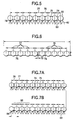
- the retainer pieces 74 and 75 are arranged as in the above embodiment, however it is different from an arrangement of those retainer pieces 74 and 75, not alternately.
- balls may be arranged to have a part where only the retainer pieces 74 are arranged while spacing adjacent balls by a distance 76, and a part where only the retainer pieces 75 are arranged while spacing adjacent balls by a distance 77.
- a remaining gap 79 may be selected to have such a size as to prevent the retainer pieces from falling down. In design, there is no need of considering the filling factor of balls.
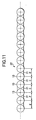
- the thickness of the retainer piece may be determined in the following manner.
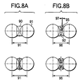
- a distance between the center points of adjacent balls is a distance 86 when the pitch of the process-waving is coincident with the ball-to-ball distance.
- a related retainer piece 90 as shown in Fig. 8A, has concave surfaces each configured so as to conform to the outer peripheral surface of a ball 91.
- the ball-to-ball distances 91 are almost equal to one another.
- a ball-to-ball distance 96 is varied by an amount of compression thickness 97 (one side) by the pressures of the balls which mutually act. This feature increases the freedom of selection of the ball-to-ball distance.
- Fig. 8A A related retainer piece 90, as shown in Fig. 8A, has concave surfaces each configured so as to conform to the outer peripheral surface of a ball 91.
- the ball-to-ball distances 91 are almost equal to one another.
- a ball-to-ball distance 96 is varied by an amount of compression thickness 97 (one side) by the pressures of the balls which mutually act. This feature increases the freedom of selection of the ball-to-ball distance.
- the retainer piece is made of metal material, and is designed to have a structure having a slit 92, thereby making the structure elastic.
- the retainer piece is made of elastic material, such as plastics or hard rubber, whereby elasticity is given to the retainer piece.
- the linear motion device in the linear motion device, there is no need of using many kinds of retainer pieces when those pieces are each assembled to between adjacent rolling elements. Therefore, the linear motion device is capable of reducing the vibrations and noises, which are ascribed to the periodical passing vibration of the rolling elements, without increasing the cost.
- the freedom of selection of retainer pieces is large, there is no need of considering the process-waving as a precondition for design, and the fitting rate of balls may easily be changed.
- the part where the pitch of the process-waving coincides with the ball-to-ball distance may easily be adjusted without changing the filling factor of balls.
Landscapes
- Engineering & Computer Science (AREA)
- General Engineering & Computer Science (AREA)
- Mechanical Engineering (AREA)
- Transmission Devices (AREA)
- Bearings For Parts Moving Linearly (AREA)
Abstract
Description
In addition to the above-mentioned effects, the following effects may also be produced.
B : distance measured between two
C : distance measured between two
D : distance measured between two
Da : diameter of the
Further, those
Claims (10)
- A linear motion guide bearing device comprising:a guide rail having rolling grooves extending in an axial direction of the linear motion guide bearing device and formed on the outer surface thereof;a slider engaged with the guide rail so as to move in the axial direction of the guide rail;a plurality of rolling elements interposed between the slider and the rolling grooves of the guide rail; anda plurality of retainer pieces each interposed between adjacent rolling elements, the retainer pieces including a plurality kinds of retainer pieces having different thicknesses, and the number of kinds of the retainer pieces is smaller than the number of the rolling elements of the rolling element series.
- The linear motion guide bearing device according to claim 1, wherein the retainer pieces are two to five kinds of retainer pieces.
- The linear motion guide bearing device according to claim 1 or 2, wherein the retainerpieces are differently colored for each of the kinds of retainer pieces having different thicknesses.
- The linear motion guide bearing device according to any of claims 1 to 3, wherein the retainer piece has an identifying mark every kind of retainer piece.
- A ball screw device comprising:a screw shaft having a first thread groove spirally formed in an outer peripheral surface thereof;a nut having a second thread groove in the inner peripheral surface thereof and being fitted to the screw shaft, the second thread groove corresponding to the first thread groove of the screw shaft;a plurality of rolling elements rollably received in a space defined between the first and second thread grooves;a circulating member fixed to the nut so as to form a circulating passage through which the rolling elements rolling along the space defined between the first and second thread grooves endlessly circulate; anda plurality of retainer pieces each interposed between adjacent rolling elements, the retainer pieces including a plurality kinds of retainer pieces having different thicknesses, and the number of kinds of the retainer pieces are smaller than the number of the rolling elements of the rolling element series.
- The ball screw device according to claim 5, wherein the retainer pieces are two to five kinds of retainer pieces.
- The ball screw device according to claim 5 or 6, wherein the retainer pieces are differently colored for each of the kinds of retainer pieces having different.
- The ball screw device according to any of claims 5 to 7, wherein the retainer piece has an identifying mark every kind of retainer piece.
- The ball screw according to claim 5, wherein the retainer pieces have each an elastic structure or are each made of elastic material.
- A method of controlling a distance of the center-to-center distance between the adjacent balls or the number of the balls by making different the thicknesses of the retainer pieces each located between the adjacent balls.
Applications Claiming Priority (2)
| Application Number | Priority Date | Filing Date | Title |
|---|---|---|---|
| JP2001144783 | 2001-05-15 | ||
| JP2001144783A JP2002339967A (en) | 2001-05-15 | 2001-05-15 | Linear motion bearing device |
Publications (3)
| Publication Number | Publication Date |
|---|---|
| EP1260722A2 true EP1260722A2 (en) | 2002-11-27 |
| EP1260722A3 EP1260722A3 (en) | 2004-01-28 |
| EP1260722B1 EP1260722B1 (en) | 2006-02-15 |
Family
ID=18990684
Family Applications (1)
| Application Number | Title | Priority Date | Filing Date |
|---|---|---|---|
| EP02010843A Expired - Lifetime EP1260722B1 (en) | 2001-05-15 | 2002-05-15 | Linear motion guide bearing device and ball screw device |
Country Status (4)
| Country | Link |
|---|---|
| US (1) | US6779419B2 (en) |
| EP (1) | EP1260722B1 (en) |
| JP (1) | JP2002339967A (en) |
| DE (1) | DE60209163T2 (en) |
Cited By (2)
| Publication number | Priority date | Publication date | Assignee | Title |
|---|---|---|---|---|
| EP1677016A4 (en) * | 2003-10-21 | 2012-05-09 | Nsk Ltd | Linear guide device |
| DE102011012889A1 (en) * | 2011-03-03 | 2012-09-06 | Neumayer Tekfor Holding Gmbh | Rolling body cage for displacement unit e.g. longitudinal shaft, in drive train of motor car, has pair of adjacent recesses exhibiting axial spacing, which is different from another axial spacing between another pair of adjacent recesses |
Families Citing this family (12)
| Publication number | Priority date | Publication date | Assignee | Title |
|---|---|---|---|---|
| JP2003269563A (en) * | 2002-03-18 | 2003-09-25 | Nsk Ltd | Ball screw |
| EP1573231B1 (en) | 2002-12-18 | 2007-04-04 | Schaeffler KG | Ball screw |
| DE10332879A1 (en) * | 2003-07-19 | 2005-02-17 | Nexpress Solutions Llc | Method for controlling a sensor device and sensor device for a printing machine |
| US7578620B2 (en) | 2003-10-21 | 2009-08-25 | Nsk Ltd. | Linear guide device |
| US7171868B2 (en) * | 2004-07-20 | 2007-02-06 | Sikorsky Aircraft Corporation | Bearing assembly |
| JP2006046530A (en) * | 2004-08-05 | 2006-02-16 | Nsk Ltd | Ball screw device |
| US7703981B2 (en) * | 2007-04-11 | 2010-04-27 | Hiwin Technologies Corp. | Linear guideway with a synchronous connector |
| US20130199314A1 (en) * | 2012-01-26 | 2013-08-08 | Roller Bearing Company Of America, Inc. | Flywheel assembly for gyroscopic applications having ball bearing slug separators |
| US9303689B2 (en) * | 2014-04-29 | 2016-04-05 | Roller Bearing Company Of America, Inc. | Non-rhythmically spaced rolling elements for reduction in bearing non-repeatable run-out |
| DE102016101811A1 (en) * | 2016-02-02 | 2017-08-03 | Accuride International Gmbh | ball cage |
| CN114346735B (en) * | 2022-01-17 | 2022-11-18 | 清华大学 | Linear feeding device |
| WO2023195713A1 (en) * | 2022-04-07 | 2023-10-12 | 주식회사 엘지에너지솔루션 | Secondary battery module and secondary battery pack comprising same |
Family Cites Families (5)
| Publication number | Priority date | Publication date | Assignee | Title |
|---|---|---|---|---|
| JP3950511B2 (en) | 1997-04-04 | 2007-08-01 | 日本トムソン株式会社 | Linear motion rolling guide unit |
| JPH11351253A (en) * | 1998-06-12 | 1999-12-24 | Nippon Seiko Kk | Ball retainer for linear motion guide device |
| JP3656440B2 (en) * | 1998-11-30 | 2005-06-08 | 日本精工株式会社 | Top ball screw |
| US6113274A (en) * | 1999-04-15 | 2000-09-05 | Tsubaki Nakashima Co., Ltd. | Linear guideway having spacers and spacer ball |
| US6415676B1 (en) * | 1999-10-26 | 2002-07-09 | Tsubaki Nakashima Co., Ltd. | Ball screw device having spacers |
-
2001
- 2001-05-15 JP JP2001144783A patent/JP2002339967A/en active Pending
-
2002
- 2002-05-14 US US10/143,978 patent/US6779419B2/en not_active Expired - Lifetime
- 2002-05-15 EP EP02010843A patent/EP1260722B1/en not_active Expired - Lifetime
- 2002-05-15 DE DE60209163T patent/DE60209163T2/en not_active Expired - Lifetime
Cited By (2)
| Publication number | Priority date | Publication date | Assignee | Title |
|---|---|---|---|---|
| EP1677016A4 (en) * | 2003-10-21 | 2012-05-09 | Nsk Ltd | Linear guide device |
| DE102011012889A1 (en) * | 2011-03-03 | 2012-09-06 | Neumayer Tekfor Holding Gmbh | Rolling body cage for displacement unit e.g. longitudinal shaft, in drive train of motor car, has pair of adjacent recesses exhibiting axial spacing, which is different from another axial spacing between another pair of adjacent recesses |
Also Published As
| Publication number | Publication date |
|---|---|
| EP1260722A3 (en) | 2004-01-28 |
| US20020178852A1 (en) | 2002-12-05 |
| DE60209163D1 (en) | 2006-04-20 |
| JP2002339967A (en) | 2002-11-27 |
| US6779419B2 (en) | 2004-08-24 |
| EP1260722B1 (en) | 2006-02-15 |
| DE60209163T2 (en) | 2006-11-16 |
Similar Documents
| Publication | Publication Date | Title |
|---|---|---|
| US6779419B2 (en) | Linear motion guide bearing device and ball screw device | |
| US7146869B2 (en) | Ball screw device and linear motion device | |
| JPH10281154A (en) | Linear motion rolling guide unit | |
| KR102466323B1 (en) | ball screw device | |
| US6619845B2 (en) | Roller retainer, direct-acting guide device and roller screw using the roller retainer | |
| EP2055990A2 (en) | Ball spline | |
| JP7194794B2 (en) | Linear guide unit | |
| JP3964926B2 (en) | Rolling device and manufacturing method thereof | |
| US6776063B2 (en) | Ball screw | |
| JP5103057B2 (en) | Roller type linear motion guide unit | |
| WO2015146811A1 (en) | Angular ball bearing | |
| US20030039414A1 (en) | Rolling element spacer in rolling guide device | |
| US6941831B2 (en) | Ball screw apparatus | |
| EP1158190A1 (en) | Linear bearing | |
| US20060016284A1 (en) | Ball screw apparatus | |
| JP2003329036A (en) | Linear motion guidance unit | |
| JP2003239964A (en) | Linear motion device | |
| US6869220B2 (en) | Linear guide device | |
| EP1318331B1 (en) | Ball screw apparatus | |
| EP1677016B1 (en) | Linear guide device | |
| US7578620B2 (en) | Linear guide device | |
| WO2006068201A1 (en) | Ball screw | |
| JP2004019860A (en) | Ball screw | |
| JP2003184985A (en) | Ball screw | |
| GB2397628A (en) | Rolling element spacer in rolling guide device |
Legal Events
| Date | Code | Title | Description |
|---|---|---|---|
| PUAI | Public reference made under article 153(3) epc to a published international application that has entered the european phase |
Free format text: ORIGINAL CODE: 0009012 |
|
| 17P | Request for examination filed |
Effective date: 20020515 |
|
| AK | Designated contracting states |
Kind code of ref document: A2 Designated state(s): AT BE CH CY DE DK ES FI FR GB GR IE IT LI LU MC NL PT SE TR |
|
| AX | Request for extension of the european patent |
Free format text: AL;LT;LV;MK;RO;SI |
|
| PUAL | Search report despatched |
Free format text: ORIGINAL CODE: 0009013 |
|
| AK | Designated contracting states |
Kind code of ref document: A3 Designated state(s): AT BE CH CY DE DK ES FI FR GB GR IE IT LI LU MC NL PT SE TR |
|
| AX | Request for extension of the european patent |
Extension state: AL LT LV MK RO SI |
|
| RIC1 | Information provided on ipc code assigned before grant |
Ipc: 7F 16C 29/06 A Ipc: 7F 16C 33/38 B Ipc: 7F 16H 25/22 B |
|
| 17Q | First examination report despatched |
Effective date: 20040607 |
|
| AKX | Designation fees paid |
Designated state(s): DE FR GB |
|
| GRAP | Despatch of communication of intention to grant a patent |
Free format text: ORIGINAL CODE: EPIDOSNIGR1 |
|
| GRAS | Grant fee paid |
Free format text: ORIGINAL CODE: EPIDOSNIGR3 |
|
| GRAA | (expected) grant |
Free format text: ORIGINAL CODE: 0009210 |
|
| AK | Designated contracting states |
Kind code of ref document: B1 Designated state(s): DE FR GB |
|
| REG | Reference to a national code |
Ref country code: GB Ref legal event code: FG4D |
|
| REF | Corresponds to: |
Ref document number: 60209163 Country of ref document: DE Date of ref document: 20060420 Kind code of ref document: P |
|
| ET | Fr: translation filed | ||
| PLBE | No opposition filed within time limit |
Free format text: ORIGINAL CODE: 0009261 |
|
| STAA | Information on the status of an ep patent application or granted ep patent |
Free format text: STATUS: NO OPPOSITION FILED WITHIN TIME LIMIT |
|
| 26N | No opposition filed |
Effective date: 20061116 |
|
| REG | Reference to a national code |
Ref country code: FR Ref legal event code: PLFP Year of fee payment: 15 |
|
| REG | Reference to a national code |
Ref country code: FR Ref legal event code: PLFP Year of fee payment: 16 |
|
| REG | Reference to a national code |
Ref country code: FR Ref legal event code: PLFP Year of fee payment: 17 |
|
| PGFP | Annual fee paid to national office [announced via postgrant information from national office to epo] |
Ref country code: DE Payment date: 20190430 Year of fee payment: 18 |
|
| PGFP | Annual fee paid to national office [announced via postgrant information from national office to epo] |
Ref country code: FR Payment date: 20190410 Year of fee payment: 18 |
|
| PGFP | Annual fee paid to national office [announced via postgrant information from national office to epo] |
Ref country code: GB Payment date: 20190515 Year of fee payment: 18 |
|
| REG | Reference to a national code |
Ref country code: DE Ref legal event code: R119 Ref document number: 60209163 Country of ref document: DE |
|
| GBPC | Gb: european patent ceased through non-payment of renewal fee |
Effective date: 20200515 |
|
| PG25 | Lapsed in a contracting state [announced via postgrant information from national office to epo] |
Ref country code: GB Free format text: LAPSE BECAUSE OF NON-PAYMENT OF DUE FEES Effective date: 20200515 Ref country code: FR Free format text: LAPSE BECAUSE OF NON-PAYMENT OF DUE FEES Effective date: 20200531 |
|
| PG25 | Lapsed in a contracting state [announced via postgrant information from national office to epo] |
Ref country code: DE Free format text: LAPSE BECAUSE OF NON-PAYMENT OF DUE FEES Effective date: 20201201 |