EP1260713A2 - Scroll compressor with Oldham coupling - Google Patents
Scroll compressor with Oldham coupling Download PDFInfo
- Publication number
- EP1260713A2 EP1260713A2 EP02250589A EP02250589A EP1260713A2 EP 1260713 A2 EP1260713 A2 EP 1260713A2 EP 02250589 A EP02250589 A EP 02250589A EP 02250589 A EP02250589 A EP 02250589A EP 1260713 A2 EP1260713 A2 EP 1260713A2
- Authority
- EP
- European Patent Office
- Prior art keywords
- key
- clearance
- slot
- oldham coupling
- accordance
- Prior art date
- Legal status (The legal status is an assumption and is not a legal conclusion. Google has not performed a legal analysis and makes no representation as to the accuracy of the status listed.)
- Granted
Links
- 230000008878 coupling Effects 0.000 title claims abstract description 47
- 238000010168 coupling process Methods 0.000 title claims abstract description 47
- 238000005859 coupling reaction Methods 0.000 title claims abstract description 47
- 239000012530 fluid Substances 0.000 description 4
- 238000007667 floating Methods 0.000 description 3
- 238000006073 displacement reaction Methods 0.000 description 2
- 230000001050 lubricating effect Effects 0.000 description 2
- 239000003921 oil Substances 0.000 description 2
- 238000005192 partition Methods 0.000 description 2
- 239000003507 refrigerant Substances 0.000 description 2
- 238000004378 air conditioning Methods 0.000 description 1
- 230000004075 alteration Effects 0.000 description 1
- 238000004891 communication Methods 0.000 description 1
- 238000001816 cooling Methods 0.000 description 1
- 239000010687 lubricating oil Substances 0.000 description 1
- 238000005461 lubrication Methods 0.000 description 1
- 230000004048 modification Effects 0.000 description 1
- 238000012986 modification Methods 0.000 description 1
- 238000005057 refrigeration Methods 0.000 description 1
- 238000007789 sealing Methods 0.000 description 1
- 238000004804 winding Methods 0.000 description 1
Images

Classifications
-
- F—MECHANICAL ENGINEERING; LIGHTING; HEATING; WEAPONS; BLASTING
- F04—POSITIVE - DISPLACEMENT MACHINES FOR LIQUIDS; PUMPS FOR LIQUIDS OR ELASTIC FLUIDS
- F04C—ROTARY-PISTON, OR OSCILLATING-PISTON, POSITIVE-DISPLACEMENT MACHINES FOR LIQUIDS; ROTARY-PISTON, OR OSCILLATING-PISTON, POSITIVE-DISPLACEMENT PUMPS
- F04C18/00—Rotary-piston pumps specially adapted for elastic fluids
- F04C18/02—Rotary-piston pumps specially adapted for elastic fluids of arcuate-engagement type, i.e. with circular translatory movement of co-operating members, each member having the same number of teeth or tooth-equivalents
-
- F—MECHANICAL ENGINEERING; LIGHTING; HEATING; WEAPONS; BLASTING
- F16—ENGINEERING ELEMENTS AND UNITS; GENERAL MEASURES FOR PRODUCING AND MAINTAINING EFFECTIVE FUNCTIONING OF MACHINES OR INSTALLATIONS; THERMAL INSULATION IN GENERAL
- F16D—COUPLINGS FOR TRANSMITTING ROTATION; CLUTCHES; BRAKES
- F16D3/00—Yielding couplings, i.e. with means permitting movement between the connected parts during the drive
- F16D3/50—Yielding couplings, i.e. with means permitting movement between the connected parts during the drive with the coupling parts connected by one or more intermediate members
- F16D3/70—Yielding couplings, i.e. with means permitting movement between the connected parts during the drive with the coupling parts connected by one or more intermediate members comprising elastic elements arranged in holes in one coupling part and surrounding pins on the other coupling part
-
- F—MECHANICAL ENGINEERING; LIGHTING; HEATING; WEAPONS; BLASTING
- F01—MACHINES OR ENGINES IN GENERAL; ENGINE PLANTS IN GENERAL; STEAM ENGINES
- F01C—ROTARY-PISTON OR OSCILLATING-PISTON MACHINES OR ENGINES
- F01C17/00—Arrangements for drive of co-operating members, e.g. for rotary piston and casing
- F01C17/06—Arrangements for drive of co-operating members, e.g. for rotary piston and casing using cranks, universal joints or similar elements
- F01C17/066—Arrangements for drive of co-operating members, e.g. for rotary piston and casing using cranks, universal joints or similar elements with an intermediate piece sliding along perpendicular axes, e.g. Oldham coupling
-
- F—MECHANICAL ENGINEERING; LIGHTING; HEATING; WEAPONS; BLASTING
- F16—ENGINEERING ELEMENTS AND UNITS; GENERAL MEASURES FOR PRODUCING AND MAINTAINING EFFECTIVE FUNCTIONING OF MACHINES OR INSTALLATIONS; THERMAL INSULATION IN GENERAL
- F16D—COUPLINGS FOR TRANSMITTING ROTATION; CLUTCHES; BRAKES
- F16D3/00—Yielding couplings, i.e. with means permitting movement between the connected parts during the drive
- F16D3/02—Yielding couplings, i.e. with means permitting movement between the connected parts during the drive adapted to specific functions
- F16D3/04—Yielding couplings, i.e. with means permitting movement between the connected parts during the drive adapted to specific functions specially adapted to allow radial displacement, e.g. Oldham couplings
Definitions
- the present invention relates to scroll machines. More particularly, the present invention relates to a scroll machine having a clearance between the scrolls and the Oldham coupling which allows deflection of the keys of the Oldham coupling.
- a class of machines exists in the art generally known as scroll machines which are used for the displacement of various types of fluid.
- the scroll machines can be configured as an expander, a displacement engine, a pump, a compressor etc. and the features of the present invention are applicable to any one of these machines.
- the disclosed embodiment is in the form of a hermetic refrigerant scroll compressor.
- Scroll compressors are becoming more and more popular for use as compressors in both refrigeration as well as air conditioning applications due primarily to their capability for extremely efficient operation.
- these machines incorporate a pair of intermeshed spiral wraps, one of which is caused to orbit relative to the other so as to define one or more moving chambers which progressively decrease in size as they travel from an outer suction port toward a center discharge port.
- An electric motor is provided which operates to drive the orbiting scroll member via a suitable drive shaft affixed to the motor rotor.
- the bottom of the hermetic shell normally contains an oil sump for lubricating and cooling purposes.
- Relative rotation between the spiral wraps is typically controlled using an Oldham coupling.
- the Oldham coupling can be keyed to the main bearing housing and the orbiting scroll member, or the Oldham coupling can be keyed to both the orbiting and the non-orbiting scroll members.
- the keys of the Oldham coupling are slidingly received within slots of the main bearing housing, the orbiting scroll member or the non-orbiting scroll member. In order to reduce the noise generated during the operation of the scroll compressor, the clearance between the keys of the Oldham coupling and its associated slot should be tightly controlled.
- the present invention addresses this by providing a scroll machine according to claim 1.
- the present invention in a preferred embodiment provides the art with a scroll compressor which includes an Oldham coupling which has both a tight tolerance fit of the keys of the Oldham coupling in their associated slots while simultaneously providing a tapered or stepped surface which provides a clearance between the key and the slot for allowing deflection of the keys of the Oldham coupling.
- the tapered or stepped surface can be located on the keys of the Oldham coupling or the tapered or stepped surface can be located on the sides of the slots within which the keys slide.
- Scroll compressor 10 comprises a generally cylindrical hermetic shell 12 having welded at the upper end thereof a cap 14 and at the lower end thereof a base 16 having a plurality of mounting feet (not shown) integrally formed therewith.
- Cap 14 is provided with a refrigerant discharge fitting 18 which may have the usual discharge valve therein.
- a transversely extending partition 20 is affixed to shell 12 by being welded about its periphery at the same point that cap 14 is welded to shell 12.
- a compressor mounting frame 22 is press fit within shell 12 and is supported by the end of base 16.
- Base 16 is slightly smaller in diameter than shell 12 such that base 16 is received within shell 12 and welded about its periphery as shown in Figure 1.
- compressor 10 Major elements of compressor 10 that are affixed to frame 22 include a two-piece main bearing housing 24, a lower bearing housing 26 and a motor stator 28.
- Crankshaft 30 has at the lower end thereof a relatively large diameter concentric bore 38 which communicates with a radially outwardly positioned smaller diameter bore 40 extending upwardly therefrom to the top of crankshaft 30.
- the lower portion of the interior of shell 12 defines an oil sump 44 which is filled with lubricating oil to a level slightly above the lower end of a rotor 46, and bore 38 acts as a pump to pump lubricating fluid up crankshaft 30 and into bore 40 and ultimately to all of the various portions of compressor 10 which require lubrication.
- Crankshaft 30 is rotatably driven by an electric motor which includes stator 28, winding 48 passing therethrough and rotor 46 press fitted on crankshaft 30.
- An upper counterweight 50 is secured to crankshaft 30 and a lower counterweight 52 is secured to rotor 46.
- the upper surface of two-piece main bearing housing 24 is provided with a flat thrust bearing surface 54 on which is disposed an orbiting scroll member 56 having the usual spiral vane or wrap 58 extending upward from an end plate 60.
- an orbiting scroll member 56 Projecting downwardly from the lower surface of end plate 60 of orbiting scroll member 56 is a cylindrical hub 62 having a journal bearing 64 therein and in which is rotatively disposed a drive bushing 66 having an inner bore in which crank pin 32 is drivingly disposed.
- Crank pin 32 has a flat on one surface which drivingly engages a flat surface formed in a portion of the inner bore of drive bushing 66 to provide a radially compliant driving arrangement, such as shown in assignee's U.S.
- Oldham coupling 68 is also provided positioned between orbiting scroll member 56 and two-piece bearing housing 24. Oldham coupling 68 is keyed to orbiting scroll member 56 and to a non-orbiting scroll member 70 to prevent rotational movement of orbiting scroll member 56.
- Non-orbiting scroll member 70 is also provided with a wrap 72 extending downwardly from an end plate 74 which is positioned in meshing engagement with wrap 58 of orbiting scroll member 56.
- Non-orbiting scroll member 70 has a centrally disposed discharge passage 76 which communicates with an upwardly open recess 78 which is in turn in fluid communication with a discharge muffler chamber 80 defined by cap 14 and partition 20.
- An annular recess 82 is also formed in non-orbiting scroll member 70 within which is disposed a floating seal assembly 84.
- Recesses 78 and 82 and floating seal assembly 84 cooperate to define axial pressure biasing chambers which receive pressurized fluid being compressed by wraps 58 and 72 so as to exert an axial biasing force on non-orbiting scroll member 70 to thereby urge the tips of respective wraps 58 and 72 into sealing engagement with the opposed end plate surfaces of end plates 74 and 60, respectively.
- Floating seal assembly 84 is preferably of the type described in greater detail in assignee's U.S. Patent No. 5,156,539, the disclosure of which is hereby incorporated herein by reference.
- Non-orbiting scroll member 70 is designed to be mounted for limited axial movement to two-piece main bearing housing 24 in a suitable manner such as disclosed in the aforementioned U.S. Patent No. 4,877,382 or assignee's U.S. Patent No. 5,102,316, the disclosure of which is hereby incorporated herein by reference.
- Oldham coupling 68 includes a ring 90, a first pair of keys 92 and a second set of keys 94. Keys 92 are each slidingly received within a slot 96 defined by orbiting scroll member 56. Keys 94 are each slidingly received within a slot 98 defined by non-orbiting scroll member 70.
- FIG. 3 illustrates the relationship between keys 92 and slots 96 and the relationship between keys 94 and slots 98.
- each key 92 and each key 94 includes a loaded surface 100 and a non-loaded surface 102.
- Non-loaded surface 102 is formed as a stepped surface.
- Stepped surface 102 defines a first clearance 104 between the lower portion of key 92 or 94 and the lower portion of slot 96 and 98, respectively.
- Stepped surface 102 also defines a second clearance 106 between the upper portion of key 92 or 94 and the upper portion of slot 96 and 98, respectively.
- First clearance 104 is designed to be a small clearance which is required for quiet operation of compressor 10.
- Second clearance 106 is designed to be larger than first clearance 104 to permit deflection of key 92 or 94 during high loading conditions for key 92 or 94.
- Oldham coupling 168 in accordance with another embodiment of the present invention is illustrated.
- Oldham coupling 168 includes keys 92 and 94 each having loaded surface 100 and a non-loaded surface 202.
- Non-loaded surface 202 is formed as a profiled surface to provide a generally tapered section to keys 92 and 94.
- Profiled surface 202 defines first clearance 104 between the lower portion of keys 92 or 94 and the lower portion of slot 96 and 98, respectively.
- Profiled surface 202 also defines second clearance 106 between the upper portion of key 92 or 94 and the upper portion of slot 96 and 98, respectively.
- first clearance 104 is designed to be a small clearance which is required for quiet operation of compressor 10.
- Second clearance 106 is designed to be larger than first clearance 104 to permit deflection of key 92 or 94 during high loading conditions for key 92 or 94.
- Oldham coupling 268 in accordance with another embodiment of the present invention is illustrated.
- Oldham coupling 268 includes keys 92 and 94 each having loaded surface 100 and a non-loaded surface 302.
- non-loaded surface 302 is designed as a straight surface which provides a generally rectangular cross section to keys 92 and 94.
- slots 96 and 98 each include a loaded surface 308 and a non-loaded surface 310.
- Non-loaded surface 308 is formed as a stepped surface. Stepped surface 308 defines first clearance 104 between the lower portion of key 92 and 94 and the lower portion of slot 96 and 98, respectively.
- Stepped surface 308 also defines second clearance 106 between the upper portion of key 92 or 94 and the upper portion of slot 96 and 98, respectively.
- First clearance 104 is designed to be a small clearance which is required for quiet operation of compressor 10.
- Second clearance 106 is designed to be larger than first clearance 104 to permit deflection of key 92 or 94 during high loading conditions for key 92 or 94. By providing a larger clearance at the upper end of key 92 or 94, deflection of key 92 or 94 within slot 96 and 98, respectively, is eliminated.
- Oldham coupling 268 is illustrated in accordance with another embodiment of the present invention.
- Oldham coupling 268 includes keys 92 and 94 each having loaded surface 100 and non-loaded surface 302.
- slots 96 and 98 each include loaded surface 308 and a non-loaded profiled surface 410.
- Non-loaded surface 308 is a profiled surface.
- Profiled surface 410 defines first clearance 104 between the lower portion of keys 92 or 94 and the lower portion of slot 96 and 98, respectively.
- Profiled surface 410 also defines second clearance 106 between the upper portion of key 92 or 94 and the upper portion of slot 96 and 98, respectively.
- First clearance 104 is designed to be a small clearance which is required for quiet operation of compressor 10.
- Second clearance 106 is designed to be larger than first clearance 104 to permit deflection of key 92 or 94 during high loading conditions for key 92 or 94. By providing a larger clearance at the upper end of key 92 or 94, deflection of key 92 or 94 within slot 96 and 98, respectively, is eliminated.
- Oldham coupling 368 in accordance with another embodiment of the present invention is illustrated.
- Oldham coupling 368 includes keys 92 and 94 each having loaded surface 100 and a non-loaded surface 502.
- Non-loaded surface 502 is formed as a stepped surface having a platform 504 extending from a base surface 506 of keys 92 and 94.
- Platform 504 defines first clearance 104 between key 92 or 94 and slot 96 and 98, respectively.
- Base surface 506 defines second clearance 106 between key 92 or 94 and slot 96 and 98, respectively.
- First clearance 104 is designed to be a small clearance which is required for quiet operation of compressor 10.
- Second clearance 106 is designed to be larger than first clearance 104 to permit deflection of key 92 or 94 during high loading conditions for key 92 or 94.
- Second clearance 106 is designed to be larger than first clearance 104 to permit deflection of key 92 or 94 during high loading conditions for key 92 or 94.
- Oldham coupling 268 is illustrated in accordance with another embodiment of the present invention.
- Oldham coupling 268 includes keys 92 and 94 each having loaded surface 100 and non-loaded surface 302.
- slots 96 and 98 each include loaded surface 308 and a non-loaded surface 510.
- Non-loaded surface 510 is formed as a stepped surface having a platform 512 extending from a base surface 514 of keys 92 and 94.
- Platform 512 defines first clearance 104 between key 92 or 94 and slot 96 and 98, respectively.
- Base surface 514 defines second clearance 106 between key 92 or 94 and slot 96 and 98, respectively.
- First clearance 104 is designed to be a small clearance required for quiet operation of compressor 10.
- Second clearance 106 is designed to be larger than first clearance 104 to permit deflection of key 92 or 94 during high loading for key 92 or 94.
- Second clearance 106 is designed to be larger than first clearance 104 to permit deflection of key 92 or 94 during high loading for key 92 or 94.
- Oldham coupling 468 in accordance with another embodiment of the present invention is illustrated.
- Oldham coupling 468 includes keys 92 and 94 each having loaded surface 100 and a non-loaded surface 602.
- Non-loaded surface 602 is formed as a tapered stepped surface having a platform 604 extending from keys 92 and 94.
- Platform 604 defines first clearance 104 between key 92 or 94 and slot 96 and 98, respectively.
- the tapered portion of platform 604 defines second clearance 106 between key 92 or 94 and slot 96 and 98, respectively.
- First clearance 104 is designed to be a small clearance which is required for quiet operation of compressor 10.
- Second clearance 106 is designed to be larger than first clearance 104 to permit deflection of key 92 or 94 during high loading conditions for key 92 or 94.
- Second clearance 106 is designed to be larger than first clearance 104 to permit deflection of key 92 or 94 during high loading conditions for key 92 or 94.
- Oldham coupling 268 is illustrated in accordance with another embodiment of the present invention.
- Oldham coupling 268 includes keys 92 and 94 each having loaded surface 100 and non-loaded surface 302.
- slots 96 and 98 each include loaded surface 308 and a non-loaded surface 610.
- Non-loaded surface 610 is formed as a tapered stepped surface having a platform 612 extending from keys 92 and 94.
- Platform 612 defines first clearance 104 between key 92 or 94 and slot 96 and 98, respectively.
- the tapered portion of platform 612 defines second clearance 106 between key 92 or 94 and slot 96 and 98, respectively.
- First clearance 104 is designed to be a small clearance required for quiet operation of compressor 10.
- Second clearance 106 is designed to be larger than first clearance 104 to permit deflection of key 92 or 94 during high loading for key 92 or 94.
- Second clearance 106 is designed to be larger than first clearance 104 to permit deflection of key 92 or 94 during high loading for key 92 or 94.
Landscapes
- Engineering & Computer Science (AREA)
- General Engineering & Computer Science (AREA)
- Mechanical Engineering (AREA)
- Rotary Pumps (AREA)
- Applications Or Details Of Rotary Compressors (AREA)
Abstract
Description
- The present invention relates to scroll machines. More particularly, the present invention relates to a scroll machine having a clearance between the scrolls and the Oldham coupling which allows deflection of the keys of the Oldham coupling.
- A class of machines exists in the art generally known as scroll machines which are used for the displacement of various types of fluid. The scroll machines can be configured as an expander, a displacement engine, a pump, a compressor etc. and the features of the present invention are applicable to any one of these machines. For purposes of illustration, however, the disclosed embodiment is in the form of a hermetic refrigerant scroll compressor.
- Scroll compressors are becoming more and more popular for use as compressors in both refrigeration as well as air conditioning applications due primarily to their capability for extremely efficient operation. Generally, these machines incorporate a pair of intermeshed spiral wraps, one of which is caused to orbit relative to the other so as to define one or more moving chambers which progressively decrease in size as they travel from an outer suction port toward a center discharge port. An electric motor is provided which operates to drive the orbiting scroll member via a suitable drive shaft affixed to the motor rotor. In a hermetic compressor, the bottom of the hermetic shell normally contains an oil sump for lubricating and cooling purposes.
- Relative rotation between the spiral wraps is typically controlled using an Oldham coupling. The Oldham coupling can be keyed to the main bearing housing and the orbiting scroll member, or the Oldham coupling can be keyed to both the orbiting and the non-orbiting scroll members. The keys of the Oldham coupling are slidingly received within slots of the main bearing housing, the orbiting scroll member or the non-orbiting scroll member. In order to reduce the noise generated during the operation of the scroll compressor, the clearance between the keys of the Oldham coupling and its associated slot should be tightly controlled.
- When the clearances between the keys of the Oldham coupling and their associated slots is tightly controlled, binding of the keys within their associated slots can occur during times of heavy loading of the Oldham coupling. This binding of the keys within the slots causes excessive loading of the keys as well as generating excessive noise.
- The present invention addresses this by providing a scroll machine according to
claim 1. - The present invention in a preferred embodiment provides the art with a scroll compressor which includes an Oldham coupling which has both a tight tolerance fit of the keys of the Oldham coupling in their associated slots while simultaneously providing a tapered or stepped surface which provides a clearance between the key and the slot for allowing deflection of the keys of the Oldham coupling. The tapered or stepped surface can be located on the keys of the Oldham coupling or the tapered or stepped surface can be located on the sides of the slots within which the keys slide.
- Other advantages and objects of the present invention will become apparent to those skilled in the art from the subsequent detailed description, appended claims and drawings.
- The present invention will now be described, by way of example only, with reference to the accompanying drawings, in which:-
- Figure 1 is a vertical cross section of a hermetic scroll compressor incorporating the unique locating and supporting system of the present invention;
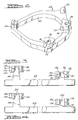
- Figure 2 is a perspective view of the Oldham coupling shown in Figure 1;
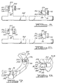
- Figure 3 is a schematic illustration of the relationship between the keys of the Oldham coupling and their associated slot in accordance with the present invention;
- Figure 4 is a schematic illustration of the relationship between the keys of the Oldham coupling and their associated slot in accordance with another embodiment of the present invention;
- Figure 5 is a schematic illustration of the relationship between the keys of the Oldham coupling and their associated slot in accordance with another embodiment of the present invention;
- Figure 6 is a schematic illustration of the relationship between the keys of the Oldham coupling and their associated slot in accordance with another embodiment of the present invention;
- Figure 7 is a perspective view of a key of an Oldham coupling in accordance with another embodiment of the present invention;
- Figure 8 is a schematic illustration of an Oldham coupling key disposed within a slot in accordance with another embodiment of the present invention;
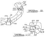
- Figure 9 is a perspective view of a key of an Oldham coupling in accordance with another embodiment of the present invention; and
- Figure 10 is a schematic illustration of an Oldham coupling key disposed within a slot in accordance with another embodiment of the present invention.
-
- Referring now to the drawings in which like reference numerals designate like or corresponding parts throughout the several views, there is shown in Figures 1 and 2 a scroll compressor incorporating the unique Oldham coupling in accordance with the present invention and which is indicated generally by the reference numeral 10. Scroll compressor 10 comprises a generally cylindrical
hermetic shell 12 having welded at the upper end thereof acap 14 and at the lower end thereof a base 16 having a plurality of mounting feet (not shown) integrally formed therewith.Cap 14 is provided with a refrigerant discharge fitting 18 which may have the usual discharge valve therein. A transversely extendingpartition 20 is affixed toshell 12 by being welded about its periphery at the same point thatcap 14 is welded toshell 12. Acompressor mounting frame 22 is press fit withinshell 12 and is supported by the end of base 16. Base 16 is slightly smaller in diameter thanshell 12 such that base 16 is received withinshell 12 and welded about its periphery as shown in Figure 1. - Major elements of compressor 10 that are affixed to
frame 22 include a two-piece main bearinghousing 24, a lower bearinghousing 26 and amotor stator 28. A drive shaft orcrankshaft 30 having aneccentric crank pin 32 at the upper end thereof is rotatably journaled in abearing 34 secured within main bearinghousing 24 and a second bearing 36 secured within lower bearinghousing 26.Crankshaft 30 has at the lower end thereof a relatively large diameterconcentric bore 38 which communicates with a radially outwardly positioned smaller diameter bore 40 extending upwardly therefrom to the top ofcrankshaft 30. The lower portion of the interior ofshell 12 defines anoil sump 44 which is filled with lubricating oil to a level slightly above the lower end of arotor 46, and bore 38 acts as a pump to pump lubricating fluid upcrankshaft 30 and into bore 40 and ultimately to all of the various portions of compressor 10 which require lubrication. -
Crankshaft 30 is rotatably driven by an electric motor which includesstator 28, winding 48 passing therethrough androtor 46 press fitted oncrankshaft 30. Anupper counterweight 50 is secured tocrankshaft 30 and alower counterweight 52 is secured torotor 46. - The upper surface of two-piece main bearing
housing 24 is provided with a flatthrust bearing surface 54 on which is disposed an orbitingscroll member 56 having the usual spiral vane orwrap 58 extending upward from anend plate 60. Projecting downwardly from the lower surface ofend plate 60 of orbitingscroll member 56 is acylindrical hub 62 having a journal bearing 64 therein and in which is rotatively disposed a drive bushing 66 having an inner bore in whichcrank pin 32 is drivingly disposed.Crank pin 32 has a flat on one surface which drivingly engages a flat surface formed in a portion of the inner bore of drive bushing 66 to provide a radially compliant driving arrangement, such as shown in assignee's U.S. Letters Patent 4,877,382, the disclosure of which is hereby incorporated herein by reference. An Oldhamcoupling 68 is also provided positioned between orbitingscroll member 56 and two-piece bearing housing 24. Oldhamcoupling 68 is keyed to orbitingscroll member 56 and to anon-orbiting scroll member 70 to prevent rotational movement of orbitingscroll member 56. -
Non-orbiting scroll member 70 is also provided with a wrap 72 extending downwardly from anend plate 74 which is positioned in meshing engagement withwrap 58 of orbitingscroll member 56.Non-orbiting scroll member 70 has a centrally disposeddischarge passage 76 which communicates with an upwardlyopen recess 78 which is in turn in fluid communication with adischarge muffler chamber 80 defined bycap 14 andpartition 20. An annular recess 82 is also formed innon-orbiting scroll member 70 within which is disposed afloating seal assembly 84. - Recesses 78 and 82 and floating
seal assembly 84 cooperate to define axial pressure biasing chambers which receive pressurized fluid being compressed bywraps 58 and 72 so as to exert an axial biasing force onnon-orbiting scroll member 70 to thereby urge the tips ofrespective wraps 58 and 72 into sealing engagement with the opposed end plate surfaces ofend plates seal assembly 84 is preferably of the type described in greater detail in assignee's U.S. Patent No. 5,156,539, the disclosure of which is hereby incorporated herein by reference.Non-orbiting scroll member 70 is designed to be mounted for limited axial movement to two-piece main bearinghousing 24 in a suitable manner such as disclosed in the aforementioned U.S. Patent No. 4,877,382 or assignee's U.S. Patent No. 5,102,316, the disclosure of which is hereby incorporated herein by reference. - The present invention relates to a unique relationship between the keys of Oldham
coupling 68, the slots defined by orbitingscroll member 56 and the slots defined bynon-orbiting scroll member 70. Referring now to Figure 2, Oldhamcoupling 68 includes aring 90, a first pair ofkeys 92 and a second set ofkeys 94. Keys 92 are each slidingly received within aslot 96 defined by orbitingscroll member 56.Keys 94 are each slidingly received within aslot 98 defined bynon-orbiting scroll member 70. - Figure 3 illustrates the relationship between
keys 92 andslots 96 and the relationship betweenkeys 94 andslots 98. Due to the rotation of the various components of compressor 10, eachkey 92 and eachkey 94 includes a loadedsurface 100 and a non-loadedsurface 102. Non-loadedsurface 102 is formed as a stepped surface. Steppedsurface 102 defines afirst clearance 104 between the lower portion ofkey slot surface 102 also defines asecond clearance 106 between the upper portion ofkey slot First clearance 104 is designed to be a small clearance which is required for quiet operation of compressor 10.Second clearance 106 is designed to be larger thanfirst clearance 104 to permit deflection ofkey key key key key slot - Referring now to Figure 4, an
Oldham coupling 168 in accordance with another embodiment of the present invention is illustrated.Oldham coupling 168 includeskeys surface 100 and anon-loaded surface 202.Non-loaded surface 202 is formed as a profiled surface to provide a generally tapered section tokeys surface 202 definesfirst clearance 104 between the lower portion ofkeys slot surface 202 also definessecond clearance 106 between the upper portion of key 92 or 94 and the upper portion ofslot first clearance 104 is designed to be a small clearance which is required for quiet operation of compressor 10.Second clearance 106 is designed to be larger thanfirst clearance 104 to permit deflection of key 92 or 94 during high loading conditions for key 92 or 94. By providing a larger clearance at the upper end of key 92 or 94, deflection of key 92 or 94 is allowed and binding of key 92 or 94 withinslot - Referring now to Figure 5, an
Oldham coupling 268 in accordance with another embodiment of the present invention is illustrated.Oldham coupling 268 includeskeys surface 100 and anon-loaded surface 302. In this embodimentnon-loaded surface 302 is designed as a straight surface which provides a generally rectangular cross section tokeys slots loaded surface 308 and anon-loaded surface 310.Non-loaded surface 308 is formed as a stepped surface. Steppedsurface 308 definesfirst clearance 104 between the lower portion ofkey slot surface 308 also definessecond clearance 106 between the upper portion of key 92 or 94 and the upper portion ofslot First clearance 104 is designed to be a small clearance which is required for quiet operation of compressor 10.Second clearance 106 is designed to be larger thanfirst clearance 104 to permit deflection of key 92 or 94 during high loading conditions for key 92 or 94. By providing a larger clearance at the upper end of key 92 or 94, deflection of key 92 or 94 withinslot - Referring now to Figure 6, Oldham coupling 268 is illustrated in accordance with another embodiment of the present invention.
Oldham coupling 268 includeskeys surface 100 andnon-loaded surface 302. In this embodiment,slots surface 308 and a non-loaded profiledsurface 410.Non-loaded surface 308 is a profiled surface. Profiledsurface 410 definesfirst clearance 104 between the lower portion ofkeys slot surface 410 also definessecond clearance 106 between the upper portion of key 92 or 94 and the upper portion ofslot First clearance 104 is designed to be a small clearance which is required for quiet operation of compressor 10.Second clearance 106 is designed to be larger thanfirst clearance 104 to permit deflection of key 92 or 94 during high loading conditions for key 92 or 94. By providing a larger clearance at the upper end of key 92 or 94, deflection of key 92 or 94 withinslot - Referring now to Figure 7, an
Oldham coupling 368 in accordance with another embodiment of the present invention is illustrated.Oldham coupling 368 includeskeys surface 100 and anon-loaded surface 502.Non-loaded surface 502 is formed as a stepped surface having aplatform 504 extending from abase surface 506 ofkeys Platform 504 definesfirst clearance 104 between key 92 or 94 andslot Base surface 506 definessecond clearance 106 between key 92 or 94 andslot First clearance 104 is designed to be a small clearance which is required for quiet operation of compressor 10.Second clearance 106 is designed to be larger thanfirst clearance 104 to permit deflection of key 92 or 94 during high loading conditions for key 92 or 94. By providing a larger clearance for a portion of the slot engaging surface of key 92 or 94, deflection of key 92 or 94 is allowed and binding of key 92 or 94 withinslot platform 504 is designed such that enough surface area remains to withstand the reverse loading that is encountered. - Referring now to Figure 8, Oldham coupling 268 is illustrated in accordance with another embodiment of the present invention.
Oldham coupling 268 includeskeys surface 100 andnon-loaded surface 302. In thisembodiment slots surface 308 and anon-loaded surface 510.Non-loaded surface 510 is formed as a stepped surface having a platform 512 extending from abase surface 514 ofkeys first clearance 104 between key 92 or 94 andslot Base surface 514 definessecond clearance 106 between key 92 or 94 andslot First clearance 104 is designed to be a small clearance required for quiet operation of compressor 10.Second clearance 106 is designed to be larger thanfirst clearance 104 to permit deflection of key 92 or 94 during high loading for key 92 or 94. By providing a larger clearance for a portion of the slot engaging surface of key 92 or 94, deflection of key 92 or 94 is allowed and binding of key 92 or 94 withinslot - Referring now to Figure 9, an
Oldham coupling 468 in accordance with another embodiment of the present invention is illustrated.Oldham coupling 468 includeskeys surface 100 and anon-loaded surface 602.Non-loaded surface 602 is formed as a tapered stepped surface having aplatform 604 extending fromkeys Platform 604 definesfirst clearance 104 between key 92 or 94 andslot platform 604 definessecond clearance 106 between key 92 or 94 andslot First clearance 104 is designed to be a small clearance which is required for quiet operation of compressor 10.Second clearance 106 is designed to be larger thanfirst clearance 104 to permit deflection of key 92 or 94 during high loading conditions for key 92 or 94. By providing a larger clearance for a portion of the slot engaging surface of key 92 or 94, deflection of key 92 or 94 is allowed and binding of key 92 or 94 withinslot platform 604 is designed such that enough surface area remains to withstand the reverse loading that is encountered. - Referring now to Figure 10, Oldham coupling 268 is illustrated in accordance with another embodiment of the present invention.
Oldham coupling 268 includeskeys surface 100 andnon-loaded surface 302. In thisembodiment slots surface 308 and anon-loaded surface 610.Non-loaded surface 610 is formed as a tapered stepped surface having aplatform 612 extending fromkeys Platform 612 definesfirst clearance 104 between key 92 or 94 andslot platform 612 definessecond clearance 106 between key 92 or 94 andslot First clearance 104 is designed to be a small clearance required for quiet operation of compressor 10.Second clearance 106 is designed to be larger thanfirst clearance 104 to permit deflection of key 92 or 94 during high loading for key 92 or 94. By providing a larger clearance for a portion of the slot engaging surface of key 92 or 94, deflection of key 92 or 94 is allowed and binding of key 92 or 94 withinslot platform 612 is designed such that enough surface area remains to withstand the reverse loading that is encountered. - While the above detailed description describes the preferred embodiment of the present invention, it should be understood that the present invention is susceptible to modification, variation and alteration without deviating from the scope of the subjoined claims.
Claims (10)
- A scroll machine comprising:an outer shell;a first scroll member disposed within said shell, said first scroll member having a first spiral wrap projecting outwardly from a first end plate;a second scroll member disposed within said shell, said second scroll member having a second spiral wrap projecting outwardly from a second end plate, said second scroll wrap being interleaved with said first spiral wrap to define a plurality of moving chambers therebetween when said second scroll member orbits with respect to said first scroll member;a coupling disposed between said second scroll member and a non-orbiting component of said scroll machine, said coupling having a first key disposed within a first slot defined by said second scroll member, said first key having a first clearance at a first side of said first slot and a second clearance at a second side of said first slot, said second clearance being greater than said first clearance.
- The scroll machine in accordance with Claim 1, wherein said first key includes a stepped surface which defines said first and second clearances.
- The scroll machine in accordance with Claim 1, wherein said first key includes a profiled surface which defines said first and second clearances.
- The scroll machine in accordance with Claim 1, wherein said first slot includes a stepped surface which defines said first and second clearances.
- The scroll machine in accordance with Claim 1, wherein said first slot includes a profiled surface which defines said first and second clearances.
- The scroll machine in accordance with any one of the preceding claims, wherein said coupling has a second key disposed within a second slot defined by said first scroll member, said second key having a third clearance at a first side of said second slot and a fourth clearance at a second side of said second slot, said fourth clearance being greater than said third clearance.
- The scroll machine in accordance with Claim 6, wherein said second key includes a stepped surface which defines said third and fourth clearance.
- The scroll machine in accordance with Claim 6, wherein said second key includes a profiled surface which defines said third and fourth clearances.
- The scroll machine in accordance with Claim 6, wherein said second slot includes a stepped surface which defines said third and fourth clearances.
- The scroll machine in accordance with Claim 6, wherein said second slot includes a profiled surface which defines said third and fourth clearances.
Applications Claiming Priority (2)
| Application Number | Priority Date | Filing Date | Title |
|---|---|---|---|
| US855273 | 2001-05-14 | ||
| US09/855,273 US6439867B1 (en) | 2001-05-14 | 2001-05-14 | Scroll compressor having a clearance for the oldham coupling |
Publications (3)
| Publication Number | Publication Date |
|---|---|
| EP1260713A2 true EP1260713A2 (en) | 2002-11-27 |
| EP1260713A3 EP1260713A3 (en) | 2003-01-02 |
| EP1260713B1 EP1260713B1 (en) | 2009-09-09 |
Family
ID=25320816
Family Applications (1)
| Application Number | Title | Priority Date | Filing Date |
|---|---|---|---|
| EP02250589A Expired - Lifetime EP1260713B1 (en) | 2001-05-14 | 2002-01-29 | Scroll compressor with Oldham coupling |
Country Status (8)
| Country | Link |
|---|---|
| US (1) | US6439867B1 (en) |
| EP (1) | EP1260713B1 (en) |
| KR (1) | KR100916554B1 (en) |
| CN (1) | CN100335792C (en) |
| AU (1) | AU780605B2 (en) |
| BR (1) | BR0201715B1 (en) |
| DE (1) | DE60233614D1 (en) |
| TW (1) | TW539809B (en) |
Cited By (2)
| Publication number | Priority date | Publication date | Assignee | Title |
|---|---|---|---|---|
| KR100916554B1 (en) * | 2001-05-14 | 2009-09-14 | 에머슨 클리메이트 테크놀로지즈 인코퍼레이티드 | Scroll compressor having a clearance for the oldham coupling |
| EP3467312A4 (en) * | 2016-05-24 | 2019-04-10 | Daikin Industries, Ltd. | VOLUME COMPRESSOR |
Families Citing this family (24)
| Publication number | Priority date | Publication date | Assignee | Title |
|---|---|---|---|---|
| US20050025650A1 (en) * | 2003-07-29 | 2005-02-03 | David Hsia | Method for fabricating a semi-hermetic scroll compressor and its structure |
| US20050057094A1 (en) * | 2003-09-16 | 2005-03-17 | Koelzer Robert L. | System for regulating the supply of power to a brake system |
| US20070101737A1 (en) | 2005-11-09 | 2007-05-10 | Masao Akei | Refrigeration system including thermoelectric heat recovery and actuation |
| US7310953B2 (en) | 2005-11-09 | 2007-12-25 | Emerson Climate Technologies, Inc. | Refrigeration system including thermoelectric module |
| US7993117B2 (en) * | 2008-01-17 | 2011-08-09 | Bitzer Scroll Inc. | Scroll compressor and baffle for same |
| US8152500B2 (en) * | 2008-01-17 | 2012-04-10 | Bitzer Scroll Inc. | Scroll compressor build assembly |
| US7963753B2 (en) * | 2008-01-17 | 2011-06-21 | Bitzer Kuhlmaschinenbau Gmbh | Scroll compressor bodies with scroll tip seals and extended thrust region |
| US7878780B2 (en) * | 2008-01-17 | 2011-02-01 | Bitzer Kuhlmaschinenbau Gmbh | Scroll compressor suction flow path and bearing arrangement features |
| US7997877B2 (en) * | 2008-01-17 | 2011-08-16 | Bitzer Kuhlmaschinenbau Gmbh | Scroll compressor having standardized power strip |
| US7878775B2 (en) * | 2008-01-17 | 2011-02-01 | Bitzer Kuhlmaschinenbau Gmbh | Scroll compressor with housing shell location |
| US7967581B2 (en) * | 2008-01-17 | 2011-06-28 | Bitzer Kuhlmaschinenbau Gmbh | Shaft mounted counterweight, method and scroll compressor incorporating same |
| US20090185927A1 (en) * | 2008-01-17 | 2009-07-23 | Bitzer Scroll Inc. | Key Coupling and Scroll Compressor Incorporating Same |
| US7918658B2 (en) * | 2008-01-17 | 2011-04-05 | Bitzer Scroll Inc. | Non symmetrical key coupling contact and scroll compressor having same |
| US9568002B2 (en) | 2008-01-17 | 2017-02-14 | Bitzer Kuehlmaschinenbau Gmbh | Key coupling and scroll compressor incorporating same |
| US8142175B2 (en) * | 2008-01-17 | 2012-03-27 | Bitzer Scroll Inc. | Mounting base and scroll compressor incorporating same |
| US7985140B2 (en) * | 2008-10-03 | 2011-07-26 | Ford Global Technologies | Zero-lash Oldham coupling |
| US8133043B2 (en) * | 2008-10-14 | 2012-03-13 | Bitzer Scroll, Inc. | Suction duct and scroll compressor incorporating same |
| US8167595B2 (en) * | 2008-10-14 | 2012-05-01 | Bitzer Scroll Inc. | Inlet screen and scroll compressor incorporating same |
| US8328543B2 (en) * | 2009-04-03 | 2012-12-11 | Bitzer Kuehlmaschinenbau Gmbh | Contoured check valve disc and scroll compressor incorporating same |
| TWM434837U (en) * | 2012-02-13 | 2012-08-01 | Fu Sheng Ind Co Ltd | Anti rotation mechanism of scroll compressor |
| US9885347B2 (en) | 2013-10-30 | 2018-02-06 | Emerson Climate Technologies, Inc. | Components for compressors having electroless coatings on wear surfaces |
| US10400770B2 (en) | 2016-02-17 | 2019-09-03 | Emerson Climate Technologies, Inc. | Compressor with Oldham assembly |
| FR3054274B1 (en) * | 2016-07-25 | 2020-02-07 | Danfoss Commercial Compressors | OLDHAM SEAL FOR A SPIRAL COMPRESSOR |
| US11136977B2 (en) | 2018-12-31 | 2021-10-05 | Emerson Climate Technologies, Inc. | Compressor having Oldham keys |
Citations (7)
| Publication number | Priority date | Publication date | Assignee | Title |
|---|---|---|---|---|
| US4877382A (en) | 1986-08-22 | 1989-10-31 | Copeland Corporation | Scroll-type machine with axially compliant mounting |
| US5102316A (en) | 1986-08-22 | 1992-04-07 | Copeland Corporation | Non-orbiting scroll mounting arrangements for a scroll machine |
| US5156539A (en) | 1990-10-01 | 1992-10-20 | Copeland Corporation | Scroll machine with floating seal |
| US5516267A (en) | 1993-09-22 | 1996-05-14 | Mitsubishi Denki Kabushiki Kaisha | Scroll compressor having a pressure relief mechanism using an oldham coupling |
| JPH09158864A (en) | 1995-12-06 | 1997-06-17 | Matsushita Electric Ind Co Ltd | Scroll compressor |
| JPH11324943A (en) | 1998-05-08 | 1999-11-26 | Mitsubishi Heavy Ind Ltd | Scroll type compressor |
| JP2001082357A (en) | 1999-09-16 | 2001-03-27 | Hitachi Ltd | Oldham couplings for scroll compressors |
Family Cites Families (12)
| Publication number | Priority date | Publication date | Assignee | Title |
|---|---|---|---|---|
| JPS6075787A (en) * | 1983-09-30 | 1985-04-30 | Toshiba Corp | Compressing device of scroll type |
| EP0479412B1 (en) * | 1990-10-01 | 1994-08-24 | Copeland Corporation | Oldham coupling for scroll compressor |
| JPH04179882A (en) * | 1990-11-09 | 1992-06-26 | Toshiba Corp | Scroll type compressor |
| JPH0610853A (en) * | 1992-06-30 | 1994-01-21 | Mitsubishi Electric Corp | Scroll compressor |
| US5988999A (en) | 1995-05-19 | 1999-11-23 | Mitsubishi Jukogyo Kabushiki Kaisha | Scroll type fluid machine having a reduced Oldham ring gap |
| JPH0932749A (en) * | 1995-07-18 | 1997-02-04 | Mitsubishi Heavy Ind Ltd | Oldham's link and scroll type fluid machine using oldham' s link |
| JPH09112448A (en) | 1995-10-18 | 1997-05-02 | Matsushita Electric Ind Co Ltd | Scroll compressor |
| JPH09158861A (en) * | 1995-12-05 | 1997-06-17 | Hitachi Ltd | Scroll compressor |
| US6027321A (en) | 1996-02-09 | 2000-02-22 | Kyungwon-Century Co. Ltd. | Scroll-type compressor having an axially displaceable scroll plate |
| JPH09250464A (en) | 1996-03-18 | 1997-09-22 | Sanden Corp | Auto-rotation prevension mechanism used for scroll type compressor |
| US5921762A (en) | 1996-06-21 | 1999-07-13 | Industrial Technology Research Institute | Oldham ring system for rotary fluid apparatus |
| US6439867B1 (en) * | 2001-05-14 | 2002-08-27 | Copeland Corporation | Scroll compressor having a clearance for the oldham coupling |
-
2001
- 2001-05-14 US US09/855,273 patent/US6439867B1/en not_active Expired - Lifetime
-
2002
- 2002-01-29 DE DE60233614T patent/DE60233614D1/en not_active Expired - Lifetime
- 2002-01-29 EP EP02250589A patent/EP1260713B1/en not_active Expired - Lifetime
- 2002-02-08 KR KR1020020007335A patent/KR100916554B1/en not_active Expired - Fee Related
- 2002-02-20 TW TW091102935A patent/TW539809B/en not_active IP Right Cessation
- 2002-02-22 CN CNB021051186A patent/CN100335792C/en not_active Expired - Lifetime
- 2002-05-07 AU AU38244/02A patent/AU780605B2/en not_active Ceased
- 2002-05-13 BR BRPI0201715-6A patent/BR0201715B1/en not_active IP Right Cessation
Patent Citations (7)
| Publication number | Priority date | Publication date | Assignee | Title |
|---|---|---|---|---|
| US4877382A (en) | 1986-08-22 | 1989-10-31 | Copeland Corporation | Scroll-type machine with axially compliant mounting |
| US5102316A (en) | 1986-08-22 | 1992-04-07 | Copeland Corporation | Non-orbiting scroll mounting arrangements for a scroll machine |
| US5156539A (en) | 1990-10-01 | 1992-10-20 | Copeland Corporation | Scroll machine with floating seal |
| US5516267A (en) | 1993-09-22 | 1996-05-14 | Mitsubishi Denki Kabushiki Kaisha | Scroll compressor having a pressure relief mechanism using an oldham coupling |
| JPH09158864A (en) | 1995-12-06 | 1997-06-17 | Matsushita Electric Ind Co Ltd | Scroll compressor |
| JPH11324943A (en) | 1998-05-08 | 1999-11-26 | Mitsubishi Heavy Ind Ltd | Scroll type compressor |
| JP2001082357A (en) | 1999-09-16 | 2001-03-27 | Hitachi Ltd | Oldham couplings for scroll compressors |
Cited By (3)
| Publication number | Priority date | Publication date | Assignee | Title |
|---|---|---|---|---|
| KR100916554B1 (en) * | 2001-05-14 | 2009-09-14 | 에머슨 클리메이트 테크놀로지즈 인코퍼레이티드 | Scroll compressor having a clearance for the oldham coupling |
| EP3467312A4 (en) * | 2016-05-24 | 2019-04-10 | Daikin Industries, Ltd. | VOLUME COMPRESSOR |
| US10815992B2 (en) | 2016-05-24 | 2020-10-27 | Daikin Industries, Ltd. | Scroll compressor having Oldham coupling with key portions and different width key gaps |
Also Published As
| Publication number | Publication date |
|---|---|
| EP1260713A3 (en) | 2003-01-02 |
| KR100916554B1 (en) | 2009-09-14 |
| BR0201715B1 (en) | 2011-07-26 |
| CN1385616A (en) | 2002-12-18 |
| AU780605B2 (en) | 2005-04-07 |
| DE60233614D1 (en) | 2009-10-22 |
| AU3824402A (en) | 2002-11-21 |
| US6439867B1 (en) | 2002-08-27 |
| CN100335792C (en) | 2007-09-05 |
| BR0201715A (en) | 2003-03-25 |
| TW539809B (en) | 2003-07-01 |
| EP1260713B1 (en) | 2009-09-09 |
| KR20020087837A (en) | 2002-11-23 |
Similar Documents
| Publication | Publication Date | Title |
|---|---|---|
| US6439867B1 (en) | Scroll compressor having a clearance for the oldham coupling | |
| AU771839B2 (en) | Scroll compressor | |
| EP1122436B1 (en) | Horizontal scroll compressor | |
| EP0066457B1 (en) | Driving support mechanism for an orbiting scroll of a scroll type fluid displacement apparatus | |
| EP0872641A1 (en) | Hermetic scroll compressor | |
| EP0479412A1 (en) | Oldham coupling for scroll compressor | |
| WO2007111903A1 (en) | Scroll machine using floating seal with backer | |
| US7390179B2 (en) | Scroll machine having counterweights with changeable cavity | |
| US6231324B1 (en) | Oldham coupling for scroll machine | |
| AU2006200293A1 (en) | Flanged sleeve guide | |
| US6179591B1 (en) | Conical hub bearing for scroll machine | |
| US5582511A (en) | Scroll machine having discharge port inserts | |
| EP1630421B1 (en) | Lubricant pump of a compressor | |
| US5489198A (en) | Scroll machine sound attenuation | |
| US6135736A (en) | Scroll machine with non-machined anti-thrust surface | |
| US20240318652A1 (en) | Drive assemblies and compressors including the same | |
| AU2012203079A1 (en) | Counterweights for balancing rotary machines |
Legal Events
| Date | Code | Title | Description |
|---|---|---|---|
| PUAI | Public reference made under article 153(3) epc to a published international application that has entered the european phase |
Free format text: ORIGINAL CODE: 0009012 |
|
| PUAL | Search report despatched |
Free format text: ORIGINAL CODE: 0009013 |
|
| AK | Designated contracting states |
Kind code of ref document: A2 Designated state(s): AT BE CH CY DE DK ES FI FR GB GR IE IT LI LU MC NL PT SE TR |
|
| AX | Request for extension of the european patent |
Free format text: AL;LT;LV;MK;RO;SI |
|
| AK | Designated contracting states |
Kind code of ref document: A3 Designated state(s): AT BE CH CY DE DK ES FI FR GB GR IE IT LI LU MC NL PT SE TR |
|
| AX | Request for extension of the european patent |
Free format text: AL;LT;LV;MK;RO;SI |
|
| RIC1 | Information provided on ipc code assigned before grant |
Free format text: 7F 04C 18/02 A, 7F 04C 23/00 B, 7F 01C 17/06 B |
|
| 17P | Request for examination filed |
Effective date: 20030404 |
|
| AKX | Designation fees paid |
Designated state(s): DE FR |
|
| RAP1 | Party data changed (applicant data changed or rights of an application transferred) |
Owner name: EMERSON CLIMATE TECHNOLOGIES, INC. |
|
| 17Q | First examination report despatched |
Effective date: 20080818 |
|
| GRAP | Despatch of communication of intention to grant a patent |
Free format text: ORIGINAL CODE: EPIDOSNIGR1 |
|
| GRAS | Grant fee paid |
Free format text: ORIGINAL CODE: EPIDOSNIGR3 |
|
| GRAA | (expected) grant |
Free format text: ORIGINAL CODE: 0009210 |
|
| AK | Designated contracting states |
Kind code of ref document: B1 Designated state(s): DE FR |
|
| REF | Corresponds to: |
Ref document number: 60233614 Country of ref document: DE Date of ref document: 20091022 Kind code of ref document: P |
|
| PLBE | No opposition filed within time limit |
Free format text: ORIGINAL CODE: 0009261 |
|
| STAA | Information on the status of an ep patent application or granted ep patent |
Free format text: STATUS: NO OPPOSITION FILED WITHIN TIME LIMIT |
|
| 26N | No opposition filed |
Effective date: 20100610 |
|
| REG | Reference to a national code |
Ref country code: FR Ref legal event code: PLFP Year of fee payment: 15 |
|
| REG | Reference to a national code |
Ref country code: FR Ref legal event code: PLFP Year of fee payment: 16 |
|
| REG | Reference to a national code |
Ref country code: FR Ref legal event code: PLFP Year of fee payment: 17 |
|
| PGFP | Annual fee paid to national office [announced via postgrant information from national office to epo] |
Ref country code: FR Payment date: 20201217 Year of fee payment: 20 |
|
| PGFP | Annual fee paid to national office [announced via postgrant information from national office to epo] |
Ref country code: DE Payment date: 20201217 Year of fee payment: 20 |
|
| REG | Reference to a national code |
Ref country code: DE Ref legal event code: R071 Ref document number: 60233614 Country of ref document: DE |