EP1260483A1 - Method and apparatus for electromagnetic irradiation of liquid - Google Patents
Method and apparatus for electromagnetic irradiation of liquid Download PDFInfo
- Publication number
- EP1260483A1 EP1260483A1 EP01906294A EP01906294A EP1260483A1 EP 1260483 A1 EP1260483 A1 EP 1260483A1 EP 01906294 A EP01906294 A EP 01906294A EP 01906294 A EP01906294 A EP 01906294A EP 1260483 A1 EP1260483 A1 EP 1260483A1
- Authority
- EP
- European Patent Office
- Prior art keywords
- liquid
- electromagnetic wave
- cylinder
- wall surface
- retention tank
- Prior art date
- Legal status (The legal status is an assumption and is not a legal conclusion. Google has not performed a legal analysis and makes no representation as to the accuracy of the status listed.)
- Withdrawn
Links
Images


Classifications
-
- B—PERFORMING OPERATIONS; TRANSPORTING
- B01—PHYSICAL OR CHEMICAL PROCESSES OR APPARATUS IN GENERAL
- B01J—CHEMICAL OR PHYSICAL PROCESSES, e.g. CATALYSIS OR COLLOID CHEMISTRY; THEIR RELEVANT APPARATUS
- B01J19/00—Chemical, physical or physico-chemical processes in general; Their relevant apparatus
- B01J19/08—Processes employing the direct application of electric or wave energy, or particle radiation; Apparatus therefor
- B01J19/12—Processes employing the direct application of electric or wave energy, or particle radiation; Apparatus therefor employing electromagnetic waves
- B01J19/122—Incoherent waves
- B01J19/123—Ultraviolet light
-
- B—PERFORMING OPERATIONS; TRANSPORTING
- B01—PHYSICAL OR CHEMICAL PROCESSES OR APPARATUS IN GENERAL
- B01J—CHEMICAL OR PHYSICAL PROCESSES, e.g. CATALYSIS OR COLLOID CHEMISTRY; THEIR RELEVANT APPARATUS
- B01J19/00—Chemical, physical or physico-chemical processes in general; Their relevant apparatus
- B01J19/08—Processes employing the direct application of electric or wave energy, or particle radiation; Apparatus therefor
- B01J19/12—Processes employing the direct application of electric or wave energy, or particle radiation; Apparatus therefor employing electromagnetic waves
- B01J19/122—Incoherent waves
- B01J19/125—X-rays
-
- B—PERFORMING OPERATIONS; TRANSPORTING
- B01—PHYSICAL OR CHEMICAL PROCESSES OR APPARATUS IN GENERAL
- B01J—CHEMICAL OR PHYSICAL PROCESSES, e.g. CATALYSIS OR COLLOID CHEMISTRY; THEIR RELEVANT APPARATUS
- B01J19/00—Chemical, physical or physico-chemical processes in general; Their relevant apparatus
- B01J19/08—Processes employing the direct application of electric or wave energy, or particle radiation; Apparatus therefor
- B01J19/12—Processes employing the direct application of electric or wave energy, or particle radiation; Apparatus therefor employing electromagnetic waves
- B01J19/122—Incoherent waves
- B01J19/127—Sunlight; Visible light
-
- B—PERFORMING OPERATIONS; TRANSPORTING
- B01—PHYSICAL OR CHEMICAL PROCESSES OR APPARATUS IN GENERAL
- B01J—CHEMICAL OR PHYSICAL PROCESSES, e.g. CATALYSIS OR COLLOID CHEMISTRY; THEIR RELEVANT APPARATUS
- B01J19/00—Chemical, physical or physico-chemical processes in general; Their relevant apparatus
- B01J19/08—Processes employing the direct application of electric or wave energy, or particle radiation; Apparatus therefor
- B01J19/12—Processes employing the direct application of electric or wave energy, or particle radiation; Apparatus therefor employing electromagnetic waves
- B01J19/122—Incoherent waves
- B01J19/128—Infrared light
-
- B—PERFORMING OPERATIONS; TRANSPORTING
- B01—PHYSICAL OR CHEMICAL PROCESSES OR APPARATUS IN GENERAL
- B01J—CHEMICAL OR PHYSICAL PROCESSES, e.g. CATALYSIS OR COLLOID CHEMISTRY; THEIR RELEVANT APPARATUS
- B01J19/00—Chemical, physical or physico-chemical processes in general; Their relevant apparatus
- B01J19/08—Processes employing the direct application of electric or wave energy, or particle radiation; Apparatus therefor
- B01J19/12—Processes employing the direct application of electric or wave energy, or particle radiation; Apparatus therefor employing electromagnetic waves
- B01J19/122—Incoherent waves
- B01J19/129—Radiofrequency
-
- B—PERFORMING OPERATIONS; TRANSPORTING
- B01—PHYSICAL OR CHEMICAL PROCESSES OR APPARATUS IN GENERAL
- B01J—CHEMICAL OR PHYSICAL PROCESSES, e.g. CATALYSIS OR COLLOID CHEMISTRY; THEIR RELEVANT APPARATUS
- B01J19/00—Chemical, physical or physico-chemical processes in general; Their relevant apparatus
- B01J19/24—Stationary reactors without moving elements inside
- B01J19/247—Suited for forming thin films
-
- C—CHEMISTRY; METALLURGY
- C02—TREATMENT OF WATER, WASTE WATER, SEWAGE, OR SLUDGE
- C02F—TREATMENT OF WATER, WASTE WATER, SEWAGE, OR SLUDGE
- C02F1/00—Treatment of water, waste water, or sewage
- C02F1/30—Treatment of water, waste water, or sewage by irradiation
- C02F1/32—Treatment of water, waste water, or sewage by irradiation with ultraviolet light
- C02F1/325—Irradiation devices or lamp constructions
-
- C—CHEMISTRY; METALLURGY
- C02—TREATMENT OF WATER, WASTE WATER, SEWAGE, OR SLUDGE
- C02F—TREATMENT OF WATER, WASTE WATER, SEWAGE, OR SLUDGE
- C02F1/00—Treatment of water, waste water, or sewage
- C02F1/38—Treatment of water, waste water, or sewage by centrifugal separation
-
- C—CHEMISTRY; METALLURGY
- C02—TREATMENT OF WATER, WASTE WATER, SEWAGE, OR SLUDGE
- C02F—TREATMENT OF WATER, WASTE WATER, SEWAGE, OR SLUDGE
- C02F1/00—Treatment of water, waste water, or sewage
- C02F1/72—Treatment of water, waste water, or sewage by oxidation
- C02F1/722—Oxidation by peroxides
-
- C—CHEMISTRY; METALLURGY
- C02—TREATMENT OF WATER, WASTE WATER, SEWAGE, OR SLUDGE
- C02F—TREATMENT OF WATER, WASTE WATER, SEWAGE, OR SLUDGE
- C02F1/00—Treatment of water, waste water, or sewage
- C02F1/72—Treatment of water, waste water, or sewage by oxidation
- C02F1/725—Treatment of water, waste water, or sewage by oxidation by catalytic oxidation
-
- C—CHEMISTRY; METALLURGY
- C02—TREATMENT OF WATER, WASTE WATER, SEWAGE, OR SLUDGE
- C02F—TREATMENT OF WATER, WASTE WATER, SEWAGE, OR SLUDGE
- C02F1/00—Treatment of water, waste water, or sewage
- C02F1/72—Treatment of water, waste water, or sewage by oxidation
- C02F1/78—Treatment of water, waste water, or sewage by oxidation with ozone
-
- C—CHEMISTRY; METALLURGY
- C02—TREATMENT OF WATER, WASTE WATER, SEWAGE, OR SLUDGE
- C02F—TREATMENT OF WATER, WASTE WATER, SEWAGE, OR SLUDGE
- C02F2101/00—Nature of the contaminant
- C02F2101/30—Organic compounds
- C02F2101/36—Organic compounds containing halogen
-
- C—CHEMISTRY; METALLURGY
- C02—TREATMENT OF WATER, WASTE WATER, SEWAGE, OR SLUDGE
- C02F—TREATMENT OF WATER, WASTE WATER, SEWAGE, OR SLUDGE
- C02F2103/00—Nature of the water, waste water, sewage or sludge to be treated
- C02F2103/06—Contaminated groundwater or leachate
-
- C—CHEMISTRY; METALLURGY
- C02—TREATMENT OF WATER, WASTE WATER, SEWAGE, OR SLUDGE
- C02F—TREATMENT OF WATER, WASTE WATER, SEWAGE, OR SLUDGE
- C02F2201/00—Apparatus for treatment of water, waste water or sewage
- C02F2201/32—Details relating to UV-irradiation devices
- C02F2201/322—Lamp arrangement
- C02F2201/3223—Single elongated lamp located on the central axis of a turbular reactor
Definitions
- the present invention relates to an apparatus for and a method of applying an electromagnetic wave to a liquid, and more particularly to an apparatus for and a method of applying an electromagnetic wave such as ultraviolet rays or the like to various liquids including water being processed in wastewater treatment plants, industrial drains, water for various uses, sewage, purified water, drinking water, pure water, ultrapure water, etc.
- an electromagnetic wave such as ultraviolet rays or the like
- electromagnetic waves such as ultraviolet rays or the like to liquids is widely used for the purposes of treating or sterilizing trace amounts of contaminants by way of excitation and/or dissociation of molecular bonds of organic substances or oxidizing agents.
- ultraviolet rays and an oxidizing agent such as ozone are used together to generate OH radicals, which decompose underwater contaminants by way of oxidization.
- the process does not produce secondary waste materials and is capable of decomposing dioxins and so on in water.
- the distance between the electromagnetic wave source and the liquid to be treated is reduced and the electromagnetic wave source and the liquid to be treated are positioned closely to each other, then the radiated intensity of the electromagnetic wave can be achieved, but it is difficult to form a stable, high-speed thin film of liquid flowing down a vertical wall surface.
- the amount of the liquid to be treated is small, a thin film of liquid can be formed which can sufficiently be irradiated with an electromagnetic wave.
- the amount of the liquid to be treated is large, however, the thickness of the film of liquid flowing down is increased, and when the speed of the flowing liquid is increased, the thin film of liquid becomes unstable, producing splashes which are scattered and contaminate the electromagnetic wave source.
- the present invention has been made in view of the above drawbacks. It is an object of the present invention to provide an apparatus for and a method of applying an electromagnetic wave to treat a large amount of liquid stably without causing an electromagnetic wave source to be contaminated.
- an electromagnetic wave applying apparatus comprises an electromagnetic wave source, a cylinder surrounding the electromagnetic wave source, a liquid retention tank disposed around the cylinder, and an inlet portion for introducing a liquid overflow from the liquid retention tank as a thin film flowing down an inner wall surface of the cylinder, which is irradiated with an electromagnetic wave from the electromagnetic wave source, wherein the inlet portion has a curved surface joining an overflow portion of the liquid retention tank to the inner wall surface of the cylinder.
- the electromagnetic wave applying apparatus can increase the amount of the liquid treated thereby without contaminating the electromagnetic wave source.
- the electromagnetic wave applying apparatus preferably includes swirling flow forming means for causing the liquid introduced from the inlet portion onto the inner wall surface of the cylinder to flow as a swirling flow down the inner wall surface.
- an electromagnetic wave applying apparatus comprises an electromagnetic wave source, a cylinder surrounding the electromagnetic wave source, a liquid retention tank disposed around the cylinder, an inlet portion for introducing a liquid overflow from the liquid retention tank as a thin film flowing down an inner wall surface of the cylinder, which is irradiated with an electromagnetic wave from the electromagnetic wave source, and swirling flow forming means for causing the liquid introduced from the inlet portion onto the inner wall surface of the cylinder to flow as a swirling flow down the inner wall surface.
- the inner wall surface of the cylinder is preferably slanted such that the diameter thereof is greater upwardly and smaller downwardly. With the slanted inner wall surface, the liquid is not peeled off the inner wall surface of the cylinder, and flows smoothly down the inner wall surface.
- the electromagnetic wave comprises ultraviolet rays and the electromagnetic wave source comprises an ultraviolet lamp.
- a method of applying an electromagnetic wave to a liquid comprises; introducing a liquid along a curved surface to an inner wall surface of a cylinder from an upper end thereof, flowing the liquid to flow as a thin film down the inner wall surface of the cylinder; and applying an electromagnetic wave from an electromagnetic wave source disposed substantially centrally in the cylinder to the liquid.
- the electromagnetic wave is preferably applied to the liquid while the liquid is flowing as a swirling thin film down the inner wall surface of the cylinder from the upper end thereof.
- a method of applying an electromagnetic wave to a liquid comprises; flowing a liquid to flow as a swirling thin film down an inner wall surface of a cylinder from the upper end thereof; and applying an electromagnetic wave to the liquid from an electromagnetic wave source disposed substantially centrally in the cylinder.
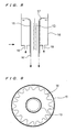
- FIG. 1 shows a cross-sectional structure of an electromagnetic wave applying apparatus according to an embodiment of the present invention
- FIG. 2 shows a plan structure of the electromagnetic wave applying apparatus.
- the electromagnetic wave applying apparatus according to the embodiment of the present invention has an ultraviolet lamp 11 disposed centrally therein for applying ultraviolet rays which are a type of electromagnetic wave and a protective tube 12 of transparent quartz glass or the like surrounding the ultraviolet lamp 11 for protecting the ultraviolet lamp 11 against direct contact with splashes.
- the ultraviolet lamp 11 and the protective tube 12 jointly make up an electromagnetic wave source 13, around which a cylinder 15 is coaxially disposed.
- the electromagnetic wave source 13 applies ultraviolet rays to a thin-film liquid layer W flowing down the inner wall surface of the cylinder 15.
- a liquid retention tank 16 is disposed around the cylinder 15 and stores a liquid which overflows the upper end of the liquid retention tank 16 and flows down the inner wall surface of the cylinder 15. If a plurality of cylinders is employed, then they may share the liquid retention tank disposed therearound.
- the upper end of the liquid retention tank 16 has an inlet portion 17 for introducing the liquid overflow as a thin film flowing down the inner wall surface of the cylinder 15 which is irradiated by the electromagnetic wave source 13.
- the inlet portion 17 is defined by a bell-mouthed surface which is curved so as to be smoothly joined to the inner wall surface of the cylinder 15.
- the electromagnetic wave applying apparatus also has a swirling flow forming means for causing the liquid to flow as a swirling flow down the inner wall surface of the cylinder 15.
- the liquid retention tank 16 has an inflow tube 18 fixedly connected to the bottom thereof for introducing the liquid into the liquid retention tank 16 tangentially to the outer circumferential surface of the liquid retention tank 16, as shown in FIG. 2.
- the introduced liquid is delivered upwardly while swirling around along the inner surface of the outer circumferential wall of the liquid retention tank 16, flows down the curved surface of the inlet portion 17 from the upper overflow end of the liquid retention tank 16, and then flows as a swirling flow down the inner wall surface of the cylinder 15.
- the liquid W is irradiated with ultraviolet rays while swirling around and flowing down as a thin film.
- the inflow tube is connected tangentially to the outer circumferential surface of the liquid retention tank 16.
- the inflow tube may be connected at any angle capable of forming a swirling flow in the liquid retention tank 16, rather than tangentially to the outer circumferential surface of the liquid retention tank 16.
- FIGS. 3A through 3C show the various shapes of the inlet portion.
- the bell-mouthed surface signifies an opening surface of a bell (a curved inner circumferential surface).
- the smoothly curved surface joins the inlet portion from the overflow end of the liquid retention tank 16 to the inner wall surface of the cylinder 15 which is substantially vertical.
- FIG. 3A shows a curved surface defined by an arc which is one-quarter of a true circle having a diameter of d.
- FIG. 3B shows a curved surface defined by an arc which is one-quarter of an oblong circle.
- FIG. 3C shows a smooth profile defined by a combination of an arc having a radius of R 1 and an arc having a radius of R 2 .
- the ratio (d/D) of the radius d of the bell-mouthed arc to the diameter D of the inner wall surface of the cylinder 15 should preferably be 0.1 or higher.
- the arc should preferably be an arc in the range from 3/16 to 8/16.
- the electromagnetic wave applying apparatus operates as follows: Ultraviolet rays which is a type of electromagnetic wave are applied from the ultraviolet lamp 11 disposed in the protective tube 12 to a thin film of the liquid W flowing down the inner wall surface of the cylinder 15.
- Ultraviolet rays which is a type of electromagnetic wave are applied from the ultraviolet lamp 11 disposed in the protective tube 12 to a thin film of the liquid W flowing down the inner wall surface of the cylinder 15.
- the liquid layer flows over the upper overflow end of the inner wall surface of the cylinder 15 and down as a thin film along the inner wall surface of the cylinder 15, it is introduced through the inlet portion 17 in the form of a curved surface onto the inner wall surface of the cylinder 15. Therefore, the overflow from the liquid retention tank 16 is smoothly introduced as a thin film onto the inner wall surface of the cylinder 15, and smoothly flows down the inner wall surface of the cylinder 15. Therefore, there is produced a downwardly flowing liquid layer of uniform thickness without producing splashes and thickness irregularities.
- the liquid swirls in the liquid retention tank 16 and forms a downwardly flowing layer from the inlet portion along the inner wall surface of the cylinder 15, the liquid is subject to centrifugal forces and has its surface stabilized and/or uniformized, so that the liquid overflow is supplied from all locations on the inlet portion at a constant rate to the inner wall surface of the cylinder 15 which is irradiated with ultraviolet rays. Since the liquid is given a swirling flow speed, even if the liquid contains suspended materials, they are prevented from being settled and/or accumulated in the liquid retention tank 16. Even when the liquid splashes, the liquid is scattered tangentially to the inner wall surface of the cylinder, rather than centrally toward the protective tube 12.
- the liquid splashes are prevented from being applied to the protective tube 12, which is thus prevented from being contaminated. Furthermore, the thickness of the liquid layer is uniformized as the liquid is subject to centrifugal forces because of the swirling flow thereof. Due to the centrifugal forces acting on the liquid, the thin-film liquid on the inner wall surface of the cylinder 15 is retained thereon for a period of time longer than if there were no swirling flow thereon.
- the inner wall surface of a cylinder 15A which is irradiated with ultraviolet rays may be progressively smaller in diameter from the upper portion to the lower portion thereof.
- the liquid layer produced by the liquid that flows in from the inlet portion is prevented from being peeled off the inner wall surface of the cylinder 15A which is irradiated with ultraviolet rays. Therefore, even when the liquid is supplied in a large quantity, a thin-film liquid layer can stably be formed on the inner wall surface of the cylinder 15A.
- the light source for supplying ultraviolet rays as an electromagnetic wave should preferably be a light source capable of emitting ultraviolet rays having wavelengths ranging from 170 to 380 nm, such as a low-pressure mercury lamp, a medium-pressure mercury lamp, a high-pressure mercury lamp, an excimer laser, a black light, or the like.
- Other electromagnetic wave sources than the ultraviolet lamp such as those for emitting any visible light, infrared rays, X-rays, gamma rays, radio waves, or the like, may be employed.
- the protective tube used to prevent the ultraviolet lamp from being damaged and smeared should preferably be made of natural quartz glass or synthetic quartz glass.
- the protective tube may be of a double-walled tube structure having two quarts tubes of different diameters, with a liquid or a gas flowing therebetween for cooling the UV lamp.
- the electromagnetic wave source 13 should preferably be installed vertically at the center of the inner wall surface of the cylinder 15 which is irradiated with ultraviolet rays. As described above, the inner wall surface of the cylinder may be slightly slanted. The electromagnetic wave source 13 thus arranged is capable of supplying an uniform amount of ultraviolet rays dose in all directions around.
- Raw liquids to be irradiated with ultraviolet rays may be polluted water including leachate from final disposal sites, industrial drains, water for various uses, sewage, etc., liquids including potable water, purified water, drinking water, pure water, ultrapure water, etc., liquids containing organic substances or organisms such as bacteria, and liquids containing, together with organic substances, oxidizing agents including ozone, hydrogen peroxide, and sodium hypochlorite, heterogeneous catalysts such as titanium dioxide, and homogeneous catalysts such as iron ions.
- Substances in the liquid to be treated may be hardly biodegradable organic substances such as fumin acid, endocrine disruptors including dioxin, bisphenol-A, nonylphenol, diethylhexyldioxane phathalate, etc., organic chlorine compounds including carcinogen, trichloroethylene, chlorophenol, pesticides, TOX (Total Organic Halogen), etc.
- escherichia coli, general bacteria, and protozoa such as cryptospordium may also be substances in the liquid to be treated.
- the inner wall of the cylinder 15 which is irradiated with electromagnetic waves may be made of synthetic resins such as vinyl chloride, metals such as stainless steel, glass, and ceramics. If the liquid is mainly composed of water, then the surface of the inner wall may be combined with a hydrophilic material such as titanium dioxide, for example, for forming a thin film of liquid more stably. If ultraviolet rays are applied to titanium dioxide, then active oxygen is generated from dissolved oxygen, making organic substances more degradable.
- the inner wall surface of the cylinder 15 which is irradiated with electromagnetic waves may be of an ordinary cylindrical shape for producing a thin-film liquid layer. For stably forming a thin-film liquid layer from a large amount of liquid, however, the inner wall surface of the cylinder should preferably have a bell-mouthed upper portion and be progressively larger in diameter upwardly in a curved configuration.
- Treating conditions in the electromagnetic wave applying apparatus may be selected depending on the amount of the liquid, the diameter and length of the electromagnetic wave source such as an ultraviolet lamp, the diameter of the protective tube, the diameter of the inner wall, and the ultraviolet rays dose.
- the electromagnetic wave source such as an ultraviolet lamp
- the diameter of the protective tube such as an ultraviolet lamp
- the diameter of the inner wall such as an ultraviolet ray
- the ultraviolet rays dose For example, treating conditions for the use of ultraviolet rays, an ultraviolet lamp having a length of 1200 mm or less, and a protective tube having a diameter in the range from 30 to 40 mm will be described below.
- the diameter of the cylinder which is irradiated with ultraviolet rays is selected normally in a range from 50 to 300 mm, or preferably in a range from 100 to 260 mm.
- the length of the portion of the cylinder which is irradiated with ultraviolet rays is longer than the ultraviolet lamp, and is selected normally in a range from 1 to 4 times the emission length of the ultraviolet lamp, or preferably in a range from 1.5 to 3 times the emission length of the ultraviolet lamp.
- the difference between the diameter of the inner circumferential surface of the outer wall of the liquid retention tank and the diameter of the outer circumferential surface of the inner wall of the liquid retention tank is selected normally in a range from 5 to 130 mm, or preferably in a range from 30 to 80 mm.
- the ultraviolet dose is selected normally in a range from 0.005 to 5.0 w ⁇ hr/l, or preferably in a range from 0.01 to 3.0 w ⁇ hr/l. If a large ultraviolet dose is required, then the liquid may be repeatedly passed through the cylinder.
- the thickness of the thin-film liquid layer flowing down the inner wall surface of the cylinder is normally in a range from 1 to 5 mm, or preferably in a range from 2 to 4 mm.
- the overflow load imposed when the liquid flows from the liquid retention tank 16 onto the inner wall surface which is irradiated with ultraviolet rays is normally in a range from 100 to 600 m 3 /m ⁇ day, or preferably in a range from 200 to 500 m 3 /m ⁇ day.
- the speed of the swirling flow in the liquid retention tank 16 is normally in a range from 20 to 100 cm/second, or preferably in a range from 30 to 80 cm/second.
- a liquid having a COD (Chemical Oxygen Demand) of 50 mg/l, TOX of 1 mg/l, an iron concentration of 5 mg/l, a manganese concentration of 5 mg/l, and a dissolved O 2 concentration of 10 mg/l was treated with ultraviolet rays under the following conditions:
- the applied intensity of the ultraviolet rays after elapse of 24 hours was 98 % of the initial level, and hence the applied intensity of the ultraviolet rays was substantially constant throughout the operating time of 24 hours.
- the COD and TOX of the treated water were 45 mg/l and 0.1 mg/l, respectively, on the average after elapse of 24 hours, and were reduced by 5 mg/l and 0.9 mg/l, respectively.
- an electromagnetic wave source (ultraviolet source) 13 comprising an ultraviolet lamp 11 sealed in a watertight fashion by a protective tube 12 of quartz glass was immersed in a liquid to be treated within a cylindrical container 20.
- the applied intensity of the ultraviolet rays after elapse of 24 hours was 10 % of the initial level, and hence the applied intensity of the ultraviolet rays had a tendency to drop greatly with time.
- the surface of the protective tube was smeared by metal components or organic substances in the treated liquid, lowering the applied intensity of the ultraviolet rays.
- the reductions in the COD, TOX, etc. were lowered.
- the COD and TOX of the treated water were 49 mg/l and 0.8 mg/l, respectively, on the average after elapse of 24 hours, and were reduced by 1 mg/l and 0.2 mg/l, respectively, which were much smaller than those in above Example 1.
- Example 1 Using the apparatus shown in FIGS. 1 and 2, a liquid having a hexachlorobenzene concentration of 10 ⁇ g/l, an iron concentration of 5 mg/l, and a manganese concentration of 5 mg/l was treated with ultraviolet rays under the same conditions as those of Example 1:
- a liquid having a COD (Chemical Oxygen Demand) of 50 mg/l, TOX of 1 mg/l, an iron concentration of 5 mg/l, a manganese concentration of 5 mg/l, and a dissolved O 2 concentration of 10 mg/l was treated with ultraviolet rays under the following conditions:
- the thin-film liquid layer on the inner wall surface of the cylinder was formed stably under the conditions of the flow rates up to 250 l/minute, and essentially no splashes were recognized.
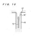
- the thickness of the thin-film liquid layer W was uniform in any location thereon as shown in FIG. 6.
- the ratio of the ultraviolet rays that have passed through the protective tube after 24 hours was 98 % or more of the initial level under any of the above conditions, and almost no reduction in the intensity of the ultraviolet rays was recognized.
- FIG. 8 shows inflow tubes 18 attached perpendicularly to a bottom wall of a liquid retention tank 16.
- these ultraviolet applying apparatus no swirling flow is developed in the liquid retention tank, and there is no swirling flow speed created on the inner wall surface of the cylinder 15.
- the thin-film liquid layer W on the inner wall surface of the cylinder suffered thickness irregularities shown in FIG. 9 at liquid flow rates starting from 100 l/minute. The liquid produced splashes much more than if a swirling flow was formed.
- the ratio of the ultraviolet rays that have passed through the protective tube after 24 hours dropped to 50 % of the initial level at liquid flow rates of 150 l/minute and higher.
- a comparison based on whether a swirling flow is produced or not indicates that the stability of the thin-film liquid layer W, the uniformity of the thickness thereof, and the flow rate load were better when a swirling flow was produced.
- the thin film was irregular, and the liquid produced fine splashes, which were attached frequently to the protective tube 12.
- the ratio of the ultraviolet rays that have passed through the protective tube after 24 hours dropped to 40 % of the initial level at a liquid flow rate of 100 l/minute.
- the cylinder described above refers to an object capable of forming a thin-film liquid layer when the liquid flows down smoothly therealong. Therefore, the concept of the cylinder according to the present invention includes a polygonal prism, an oblate cylinder, or a similar shape which is effective to provide the above effect.
- a large amount of liquid can be treated by being stably irradiated with an electromagnetic wave.
- the electromagnetic wave is applied from the electromagnetic wave source disposed in the protective tube to the liquid flowing as a thin film down the inner wall surface which is irradiated with the electromagnetic wave.
- the inlet portion for introducing the liquid overflow from the liquid retention tank onto the inner wall surface of the cylinder has a curved surface, the state of the surface of the liquid is stabilized and/or uniformized, and the liquid overflow is supplied from all locations on the inlet portion smoothly at a constant speed.
- a swirling flow speed is given to the liquid, even if the liquid contains suspended materials, they are prevented from being settled and/or accumulated in the liquid retention tank.
- the present invention is concerned with an apparatus for and a method of applying an electromagnetic wave such as ultraviolet rays or the like to various liquids including water being processed in wastewater treatment plants, industrial drains, water for various uses, sewage, purified water, drinking water, pure water, ultrapure water, etc.
- the invention is appropriately applicable to water treatments in various fields for decomposing trace amounts of contaminants by applying an electromagnetic wave such as ultraviolet rays or the like to various liquids in the above fields.
Landscapes
- Chemical & Material Sciences (AREA)
- Organic Chemistry (AREA)
- Health & Medical Sciences (AREA)
- Toxicology (AREA)
- Chemical Kinetics & Catalysis (AREA)
- Physics & Mathematics (AREA)
- Electromagnetism (AREA)
- General Health & Medical Sciences (AREA)
- Life Sciences & Earth Sciences (AREA)
- Hydrology & Water Resources (AREA)
- Engineering & Computer Science (AREA)
- Environmental & Geological Engineering (AREA)
- Water Supply & Treatment (AREA)
- Physical Water Treatments (AREA)
- Physical Or Chemical Processes And Apparatus (AREA)
- Organic Low-Molecular-Weight Compounds And Preparation Thereof (AREA)
Abstract
Description
Claims (8)
- An electromagnetic wave applying apparatus comprising:wherein said inlet portion has a curved surface joining an overflow portion of said liquid retention tank to the inner wall surface of said cylinder.an electromagnetic wave source;a cylinder surrounding said electromagnetic wave source;a liquid retention tank disposed around said cylinder; andan inlet portion for introducing a liquid overflow from said liquid retention tank as a thin film flowing down an inner wall surface of said cylinder, which is irradiated with an electromagnetic wave from said electromagnetic wave source;
- An electromagnetic wave applying apparatus according to claim 1, wherein swirling flow forming means is provided for causing the liquid introduced from said inlet portion onto the inner wall surface of said cylinder to flow as a swirling flow down said inner wall surface.
- An electromagnetic wave applying apparatus comprising:wherein swirling flow forming means is provided for causing the liquid introduced from said inlet portion onto the inner wall surface of said cylinder to flow as a swirling flow down said inner wall surface.an electromagnetic wave source;a cylinder surrounding said electromagnetic wave source;a liquid retention tank disposed around said cylinder;an inlet portion for introducing a liquid overflow from said liquid retention tank as a thin film flowing down an inner wall surface of said cylinder, which is irradiated with an electromagnetic wave from said electromagnetic wave source;
- An electromagnetic wave applying apparatus according to any one of claims 1 through 3, wherein said inner wall surface of said cylinder is slanted such that a diameter thereof is greater upwardly and smaller downwardly.
- An electromagnetic wave applying apparatus according to any one of claims 1 through 4, wherein said electromagnetic wave comprises ultraviolet rays and said electromagnetic wave source comprises an ultraviolet lamp.
- A method of applying an electromagnetic wave to a liquid, comprising:introducing a liquid along a curved surface to an inner wall surface of a cylinder from an upper end thereof;flowing down said liquid as a thin film along said inner wall surface of the cylinder; andapplying an electromagnetic wave to said liquid from an electromagnetic wave source disposed substantially centrally in said cylinder.
- A method of applying an electromagnetic wave to a liquid according to claim 6, wherein said electromagnetic wave is applied to the liquid while said liquid is flowing as a swirling thin film down said inner wall surface of the cylinder from upper end thereof.
- A method of applying an electromagnetic wave to a liquid, comprising:flowing down a liquid to flow as a swirling thin film down an inner wall surface of a cylinder from upper end thereof; andapplying an electromagnetic wave to said liquid from an electromagnetic wave source disposed substantially centrally in said cylinder.
Applications Claiming Priority (3)
| Application Number | Priority Date | Filing Date | Title |
|---|---|---|---|
| JP2000049657 | 2000-02-25 | ||
| JP2000049657 | 2000-02-25 | ||
| PCT/JP2001/001401 WO2001062671A1 (en) | 2000-02-25 | 2001-02-26 | Method and apparatus for electromagnetic irradiation of liquid |
Publications (2)
| Publication Number | Publication Date |
|---|---|
| EP1260483A1 true EP1260483A1 (en) | 2002-11-27 |
| EP1260483A4 EP1260483A4 (en) | 2007-08-01 |
Family
ID=18571562
Family Applications (1)
| Application Number | Title | Priority Date | Filing Date |
|---|---|---|---|
| EP01906294A Withdrawn EP1260483A4 (en) | 2000-02-25 | 2001-02-26 | Method and apparatus for electromagnetic irradiation of liquid |
Country Status (5)
| Country | Link |
|---|---|
| US (1) | US6713771B2 (en) |
| EP (1) | EP1260483A4 (en) |
| JP (1) | JP4090241B2 (en) |
| AU (1) | AU2001234172A1 (en) |
| WO (1) | WO2001062671A1 (en) |
Cited By (2)
| Publication number | Priority date | Publication date | Assignee | Title |
|---|---|---|---|---|
| FR2998486A1 (en) * | 2012-11-28 | 2014-05-30 | Alfaa France | DEVICE FOR TREATING FLUID |
| GB2567817A (en) * | 2017-10-24 | 2019-05-01 | Ipurtech Ltd | Treating thin film with UV radiation |
Families Citing this family (23)
| Publication number | Priority date | Publication date | Assignee | Title |
|---|---|---|---|---|
| US10188119B2 (en) | 2001-07-16 | 2019-01-29 | Foret Plasma Labs, Llc | Method for treating a substance with wave energy from plasma and an electrical arc |
| US7857972B2 (en) | 2003-09-05 | 2010-12-28 | Foret Plasma Labs, Llc | Apparatus for treating liquids with wave energy from an electrical arc |
| US8734643B2 (en) | 2001-07-16 | 2014-05-27 | Foret Plasma Labs, Llc | Apparatus for treating a substance with wave energy from an electrical arc and a second source |
| US7622693B2 (en) * | 2001-07-16 | 2009-11-24 | Foret Plasma Labs, Llc | Plasma whirl reactor apparatus and methods of use |
| US9481584B2 (en) * | 2001-07-16 | 2016-11-01 | Foret Plasma Labs, Llc | System, method and apparatus for treating liquids with wave energy from plasma |
| US8734654B2 (en) | 2001-07-16 | 2014-05-27 | Foret Plasma Labs, Llc | Method for treating a substance with wave energy from an electrical arc and a second source |
| US7422695B2 (en) | 2003-09-05 | 2008-09-09 | Foret Plasma Labs, Llc | Treatment of fluids with wave energy from a carbon arc |
| US8981250B2 (en) | 2001-07-16 | 2015-03-17 | Foret Plasma Labs, Llc | Apparatus for treating a substance with wave energy from plasma and an electrical Arc |
| US8764978B2 (en) | 2001-07-16 | 2014-07-01 | Foret Plasma Labs, Llc | System for treating a substance with wave energy from an electrical arc and a second source |
| WO2005033013A1 (en) * | 2003-10-05 | 2005-04-14 | Taizou Aoyama | Method of radiating light beam to liquid |
| WO2005062946A2 (en) * | 2003-12-23 | 2005-07-14 | San Diego State University Foundation | Perchlorate removal apparatus |
| US6991733B2 (en) * | 2004-05-25 | 2006-01-31 | Industrial Technology Research Institute | Process for removing organics from ultrapure water |
| US7241380B2 (en) * | 2005-06-15 | 2007-07-10 | Reiling Dennis R | Ultraviolet treatment unit and septic tank system |
| NZ542509A (en) * | 2005-09-20 | 2008-01-31 | Logistic Solutions Ltd | A treatment system |
| AT508099B1 (en) | 2009-03-17 | 2015-07-15 | Semperit Ag Holding | METHOD FOR PRODUCING A NETWORKED ELASTOMER |
| JP5818628B2 (en) * | 2011-10-24 | 2015-11-18 | 太平洋セメント株式会社 | Non-liquid substance manufacturing method and non-liquid substance manufacturing apparatus |
| CA2894535C (en) | 2012-12-11 | 2018-05-29 | Foret Plasma Labs, Llc | High temperature countercurrent vortex reactor system, method and apparatus |
| US10135236B2 (en) * | 2013-02-20 | 2018-11-20 | The Board of Regents of the Nevada Systems of Higher Education on behalf of the University of Nevada, Las Vegas | Auto-triggered methods and systems for protecting against direct and indirect electronic attack |
| EP2971488B1 (en) | 2013-03-12 | 2018-09-26 | Foret Plasma Labs, Llc | Apparatus and method for sintering proppants |
| JP5853982B2 (en) * | 2013-03-29 | 2016-02-09 | 三浦工業株式会社 | UV sterilizer and UV sterilizer system |
| JP6404404B1 (en) * | 2017-06-06 | 2018-10-10 | 日機装株式会社 | Fluid sterilizer |
| JP7035499B2 (en) * | 2017-12-14 | 2022-03-15 | 豊田合成株式会社 | Ultraviolet light irradiation sterilizer |
| WO2020016873A2 (en) * | 2018-07-18 | 2020-01-23 | Lebaron E Shem | System and method for treatment of a process fluid to inactivate undesirable organisms |
Family Cites Families (17)
| Publication number | Priority date | Publication date | Assignee | Title |
|---|---|---|---|---|
| GB450341A (en) * | 1934-12-24 | 1936-07-15 | Creamery Package Mfg Co | Improvements in liquid irradiating apparatus |
| NL282311A (en) * | 1964-01-14 | |||
| US3659096A (en) * | 1970-06-16 | 1972-04-25 | Controlex Corp America | Apparatus for irradiating a liquid |
| DE2258393B1 (en) * | 1972-11-29 | 1973-10-11 | Licentia Gmbh | Process and device for the irradiation of liquids and similar media with high-energy electrons |
| JPS5523662Y2 (en) * | 1974-11-01 | 1980-06-05 | ||
| JPS5159449A (en) | 1974-11-21 | 1976-05-24 | Mitsui Mining & Smelting Co | Kendakuekino shoriho |
| DE2527009C3 (en) * | 1975-06-18 | 1979-05-31 | Original Hanau Quarzlampen Gmbh, 6450 Hanau | Device for UV disinfection of water |
| US4274970A (en) * | 1979-10-29 | 1981-06-23 | Beitzel Stuart W | Method and apparatus for treating water |
| JP2757213B2 (en) | 1989-09-22 | 1998-05-25 | 日本原子力研究所 | Water sterilizer |
| DE4136949A1 (en) * | 1991-11-11 | 1993-05-13 | Roswitha Niedermeier | Photoactive purificn. of water contg. organic impurities - by passing thin film of water over UV light source which contains wavelengths suitable for formation of ozone molecules and hydroxyl radical |
| JP3301499B2 (en) * | 1993-02-15 | 2002-07-15 | 株式会社荏原製作所 | Electromagnetic wave irradiation device for liquid |
| DE4317939C2 (en) * | 1993-04-27 | 1995-09-28 | Darius Jung | Device for optimizing the intensity of the radiation aimed at liquid waste and waste water to be irradiated |
| US5503800A (en) * | 1994-03-10 | 1996-04-02 | Uv Systems Technology, Inc. | Ultra-violet sterilizing system for waste water |
| FR2729382B1 (en) * | 1995-01-16 | 1997-03-28 | Omnium Traitement Valorisa | UV IRRADIATION REACTOR FOR THE TREATMENT OF LIQUIDS |
| JP3109986B2 (en) | 1996-03-22 | 2000-11-20 | シャープ株式会社 | Signal transition detection circuit |
| GB2318264A (en) * | 1996-10-14 | 1998-04-15 | Malcolm James Robins | Liquid steriliser |
| AUPP158098A0 (en) * | 1998-01-29 | 1998-02-26 | Arnold, Geoffery Peter | Laser alignment apparatus and method |
-
2001
- 2001-02-26 AU AU2001234172A patent/AU2001234172A1/en not_active Abandoned
- 2001-02-26 EP EP01906294A patent/EP1260483A4/en not_active Withdrawn
- 2001-02-26 JP JP2001561687A patent/JP4090241B2/en not_active Expired - Fee Related
- 2001-02-26 WO PCT/JP2001/001401 patent/WO2001062671A1/en not_active Ceased
- 2001-02-26 US US10/204,599 patent/US6713771B2/en not_active Expired - Fee Related
Cited By (3)
| Publication number | Priority date | Publication date | Assignee | Title |
|---|---|---|---|---|
| FR2998486A1 (en) * | 2012-11-28 | 2014-05-30 | Alfaa France | DEVICE FOR TREATING FLUID |
| WO2014083284A1 (en) * | 2012-11-28 | 2014-06-05 | Alfaa France | Device for treating a fluid using ultraviolet rays |
| GB2567817A (en) * | 2017-10-24 | 2019-05-01 | Ipurtech Ltd | Treating thin film with UV radiation |
Also Published As
| Publication number | Publication date |
|---|---|
| AU2001234172A1 (en) | 2001-09-03 |
| US6713771B2 (en) | 2004-03-30 |
| WO2001062671A1 (en) | 2001-08-30 |
| JP4090241B2 (en) | 2008-05-28 |
| EP1260483A4 (en) | 2007-08-01 |
| US20030141457A1 (en) | 2003-07-31 |
Similar Documents
| Publication | Publication Date | Title |
|---|---|---|
| US6713771B2 (en) | Method and apparatus for electromagnetic irradiation of liquid | |
| JPWO2001062671A1 (en) | Apparatus and method for irradiating electromagnetic waves onto liquid | |
| CA1139460A (en) | Disinfection and purification of fluids using focused laser radiation | |
| US6991735B2 (en) | Free radical generator and method | |
| EP0671363B1 (en) | Method and system for treating polluted water | |
| Pérez et al. | Fenton and photo-Fenton oxidation of textile effluents | |
| KR950006684B1 (en) | Process and apparatus for the decomposition of organochlorine solvent contained in water | |
| JP2010504199A (en) | Apparatus and method for treating ballast water with ultraviolet radiation means and catalyst. | |
| Hand et al. | Destruction of DBP precursors with catalytic oxidation | |
| Das et al. | Ozone-based oxidation processes for the removal of pharmaceutical products from wastewater | |
| JP3797552B2 (en) | Ultraviolet irradiation treatment method and apparatus | |
| Trousil et al. | Paracetamol and ibuprofen removal from aqueous solutions by ozonation and photochemical processes | |
| JP2001259620A (en) | Water treating device by semiconductor photocatalyst using microwave and uv ray jointly | |
| Ku et al. | Decomposition of monocrotophos in aqueous solution by UV irradiation in the presence of titanium dioxide | |
| JPH1034171A (en) | Wastewater treatment method by ultraviolet rays | |
| JPH10337579A (en) | Sewage treatment method and treatment device | |
| KR200434724Y1 (en) | Wastewater Sterilization and Purification | |
| JP3576474B2 (en) | Decomposition method of dioxins | |
| JPH01236986A (en) | Method and apparatus for treating liquid by ultraviolet irradiation | |
| JP3573322B2 (en) | Method and apparatus for treating dioxin-containing wastewater | |
| JPH11300345A (en) | Method and apparatus for decomposing organic chlorine compounds such as dioxins in landfill leachate | |
| KR100399153B1 (en) | Water treatment system for production of industrial water from secondary effluent by gamma irradiation and TiO2 | |
| JP2003310741A (en) | Ultraviolet irradiating device | |
| JP3745055B2 (en) | Method and apparatus for processing liquid containing organic matter | |
| KR100411022B1 (en) | Photocatalyst apparatus for purification of wastewater |
Legal Events
| Date | Code | Title | Description |
|---|---|---|---|
| PUAI | Public reference made under article 153(3) epc to a published international application that has entered the european phase |
Free format text: ORIGINAL CODE: 0009012 |
|
| 17P | Request for examination filed |
Effective date: 20020904 |
|
| AK | Designated contracting states |
Kind code of ref document: A1 Designated state(s): AT BE CH CY DE DK ES FI FR GB GR IE IT LI LU MC NL PT SE TR |
|
| AX | Request for extension of the european patent |
Free format text: AL;LT;LV;MK;RO;SI |
|
| RBV | Designated contracting states (corrected) |
Designated state(s): AT BE CH DE FR GB LI |
|
| A4 | Supplementary search report drawn up and despatched |
Effective date: 20070704 |
|
| RIC1 | Information provided on ipc code assigned before grant |
Ipc: C02F 1/30 20060101AFI20010903BHEP Ipc: C02F 1/32 20060101ALI20070628BHEP |
|
| 17Q | First examination report despatched |
Effective date: 20080318 |
|
| STAA | Information on the status of an ep patent application or granted ep patent |
Free format text: STATUS: THE APPLICATION IS DEEMED TO BE WITHDRAWN |
|
| 18D | Application deemed to be withdrawn |
Effective date: 20080729 |