EP1260300A2 - A method of manufacturing an article - Google Patents
A method of manufacturing an article Download PDFInfo
- Publication number
- EP1260300A2 EP1260300A2 EP02253208A EP02253208A EP1260300A2 EP 1260300 A2 EP1260300 A2 EP 1260300A2 EP 02253208 A EP02253208 A EP 02253208A EP 02253208 A EP02253208 A EP 02253208A EP 1260300 A2 EP1260300 A2 EP 1260300A2
- Authority
- EP
- European Patent Office
- Prior art keywords
- integral structure
- sheet metal
- depositing
- weld
- metal
- Prior art date
- Legal status (The legal status is an assumption and is not a legal conclusion. Google has not performed a legal analysis and makes no representation as to the accuracy of the status listed.)
- Granted
Links
Images


Classifications
-
- B—PERFORMING OPERATIONS; TRANSPORTING
- B23—MACHINE TOOLS; METAL-WORKING NOT OTHERWISE PROVIDED FOR
- B23P—METAL-WORKING NOT OTHERWISE PROVIDED FOR; COMBINED OPERATIONS; UNIVERSAL MACHINE TOOLS
- B23P15/00—Making specific metal objects by operations not covered by a single other subclass or a group in this subclass
- B23P15/04—Making specific metal objects by operations not covered by a single other subclass or a group in this subclass turbine or like blades from several pieces
-
- B—PERFORMING OPERATIONS; TRANSPORTING
- B23—MACHINE TOOLS; METAL-WORKING NOT OTHERWISE PROVIDED FOR
- B23K—SOLDERING OR UNSOLDERING; WELDING; CLADDING OR PLATING BY SOLDERING OR WELDING; CUTTING BY APPLYING HEAT LOCALLY, e.g. FLAME CUTTING; WORKING BY LASER BEAM
- B23K20/00—Non-electric welding by applying impact or other pressure, with or without the application of heat, e.g. cladding or plating
- B23K20/02—Non-electric welding by applying impact or other pressure, with or without the application of heat, e.g. cladding or plating by means of a press ; Diffusion bonding
-
- B—PERFORMING OPERATIONS; TRANSPORTING
- B23—MACHINE TOOLS; METAL-WORKING NOT OTHERWISE PROVIDED FOR
- B23K—SOLDERING OR UNSOLDERING; WELDING; CLADDING OR PLATING BY SOLDERING OR WELDING; CUTTING BY APPLYING HEAT LOCALLY, e.g. FLAME CUTTING; WORKING BY LASER BEAM
- B23K9/00—Arc welding or cutting
- B23K9/04—Welding for other purposes than joining, e.g. built-up welding
- B23K9/044—Built-up welding on three-dimensional surfaces
-
- B—PERFORMING OPERATIONS; TRANSPORTING
- B23—MACHINE TOOLS; METAL-WORKING NOT OTHERWISE PROVIDED FOR
- B23K—SOLDERING OR UNSOLDERING; WELDING; CLADDING OR PLATING BY SOLDERING OR WELDING; CUTTING BY APPLYING HEAT LOCALLY, e.g. FLAME CUTTING; WORKING BY LASER BEAM
- B23K2101/00—Articles made by soldering, welding or cutting
- B23K2101/001—Turbines
-
- Y—GENERAL TAGGING OF NEW TECHNOLOGICAL DEVELOPMENTS; GENERAL TAGGING OF CROSS-SECTIONAL TECHNOLOGIES SPANNING OVER SEVERAL SECTIONS OF THE IPC; TECHNICAL SUBJECTS COVERED BY FORMER USPC CROSS-REFERENCE ART COLLECTIONS [XRACs] AND DIGESTS
- Y10—TECHNICAL SUBJECTS COVERED BY FORMER USPC
- Y10T—TECHNICAL SUBJECTS COVERED BY FORMER US CLASSIFICATION
- Y10T29/00—Metal working
- Y10T29/49—Method of mechanical manufacture
- Y10T29/49316—Impeller making
- Y10T29/49336—Blade making
-
- Y—GENERAL TAGGING OF NEW TECHNOLOGICAL DEVELOPMENTS; GENERAL TAGGING OF CROSS-SECTIONAL TECHNOLOGIES SPANNING OVER SEVERAL SECTIONS OF THE IPC; TECHNICAL SUBJECTS COVERED BY FORMER USPC CROSS-REFERENCE ART COLLECTIONS [XRACs] AND DIGESTS
- Y10—TECHNICAL SUBJECTS COVERED BY FORMER USPC
- Y10T—TECHNICAL SUBJECTS COVERED BY FORMER US CLASSIFICATION
- Y10T29/00—Metal working
- Y10T29/49—Method of mechanical manufacture
- Y10T29/49316—Impeller making
- Y10T29/49336—Blade making
- Y10T29/49339—Hollow blade
-
- Y—GENERAL TAGGING OF NEW TECHNOLOGICAL DEVELOPMENTS; GENERAL TAGGING OF CROSS-SECTIONAL TECHNOLOGIES SPANNING OVER SEVERAL SECTIONS OF THE IPC; TECHNICAL SUBJECTS COVERED BY FORMER USPC CROSS-REFERENCE ART COLLECTIONS [XRACs] AND DIGESTS
- Y10—TECHNICAL SUBJECTS COVERED BY FORMER USPC
- Y10T—TECHNICAL SUBJECTS COVERED BY FORMER US CLASSIFICATION
- Y10T29/00—Metal working
- Y10T29/49—Method of mechanical manufacture
- Y10T29/49805—Shaping by direct application of fluent pressure
Definitions
- the present invention relates to a method of manufacturing an article, particularly to a method of manufacturing an article from sheet metal workpieces and more particularly to a method of manufacturing an article from sheet metal workpieces by diffusion bonding and hot forming.
- a problem with the manufacture of a fan outlet guide vane is that attachment features are required on the radially inner and outer ends of the fan outlet guide vane to enable the fan outlet guide vane to be attached at the radially inner end to a core engine casing and to be attached at the radially outer end to a fan casing.
- titanium pieces are forged to produce locally thickened end portions suitable for a fastener, a bolt, to pass through to retain the fan outlet guide vane on the core engine casing or fan casing.
- the titanium piece is machined to size and is welded to the radially inner end or radially outer end of the fan outlet guide vane.
- a problem with the manufacture of a fan blade is that attachment features are required on the radially inner end of the fan blade to enable the fan blade to be attached at the radially inner end to a fan rotor.
- the present invention seeks to provide a novel method of manufacturing an article from sheet metal workpieces which reduces, preferably overcomes, the above mentioned problems.
- the present invention provides a method of manufacturing a sheet metal article comprising forming a sheet metal article from at least one sheet metal workpiece, weld-depositing metal at at least one predetermined position and in a predetermined shape to build up a feature to net shape at the at least one predetermined position on the sheet metal article.
- the method comprises selecting at least two sheet metal workpieces, assembling the at least two sheet metal workpieces in a stack of sheet metal workpieces, sealing the edges of the stack of sheet metal workpieces, diffusing bonding the stack of sheet metal workpieces in areas other than a predetermined pattern to form an integral structure, weld-depositing metal at at least one predetermined position and in a predetermined shape to build up a feature to net shape at the at least one predetermined position on the integral structure, and heating the integral structure and internally pressurising the interior of the integral structure to hot form at least one of the at least two metal workpieces to form a hollow integral structure of predetermined shape.
- the method comprises weld-depositing metal at at least one predetermined position at one end of the hollow integral structure.
- the method comprises weld-depositing metal at two predetermined positions.
- the method may comprise weld-depositing metal at both ends of the hollow integral structure, weld-depositing the metal in a predetermined position and in a predetermined shape to build up features to net shape at both ends of the hollow integral structure.
- the method may comprise weld-depositing metal at both sides at one end of the hollow integral structure, depositing the metal in a predetermined position and in a predetermined shape to build up a feature to net shape at both sides of the hollow integral structure.
- the method may comprise weld-depositing metal at both sides at both ends of the hollow integral structure, depositing the metal in a predetermined position and in a predetermined shape to build up a feature to net shape at both sides at both ends of the hollow integral structure.
- the method may comprise weld-depositing metal at one end and at one side of the hollow integral structure, depositing the metal in a predetermined position and in a predetermined shape to build up a feature to net shape at one end and on one side of the hollow integral structure.
- the article is a fan outlet guide vane or a compressor vane.
- the method comprises weld-depositing the metal to build up a boss at at least one end of the article.
- the method comprises drilling an aperture through the boss.
- the article is a fan blade or compressor blade.
- the method may comprise weld-depositing the metal to build up a dovetail root or a firtree root at one end of the article.
- the sheet metal article comprises titanium or a titanium alloy.
- the method comprises weld-depositing titanium or a titanium alloy.
- the titanium alloy comprises 6wt% Al, 4wt% and the balance is titanium plus incidental impurities.
- the sheet metal article comprises a nickel alloy.
- the method comprises weld-depositing a nickel alloy.
- the nickel alloy comprises 19wt% Cr, 18wt% Fe, 5wt%Nb, 3wt% Mo, 0.9wt% Ti, 0.5wt% Al and the balance Ni plus incidental impurities.
- a stop off material is applied in a predetermined pattern to at least one surface of at least one of the at least two sheet metal workpieces before assembling the at least two sheet metal workpieces in a stack of sheet metal workpieces.
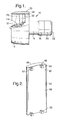
- a turbofan gas turbine engine 10 as shown in figure 1, comprises in flow series an inlet 12, a fan section 14, a compressor section 16, a combustion section 18, a turbine section 20 and an exhaust nozzle 22.
- the turbine section 20 comprises one or more turbines arranged to drive the compressor section 16 via one or more shafts (not shown) and one or more turbines arranged to drive the fan section 14 via one or more shafts (not shown).
- the fan section 14 comprises a fan rotor 24, which carries a plurality of circumferentially arranged radially outwardly extending fan blades 26.
- the fan blades 26 are surrounded by a fan casing 30 arranged coaxially with the axis X of the turbofan gas turbine engine 10.
- the fan casing 30 partially defines a fan duct 32 and the fan casing 30 is secured to a core engine casing 32 by a plurality of radially extending fan outlet guide vanes 34.
- Each fan outlet guide vane 34 comprises a radially inner end 36, an aerofoil portion 38 and a radially outer end 40.
- the radially outer end 40 has two axially spaced bosses 42 and 44 through which apertures 46 and 48 respectively are formed.
- the apertures 46 and 48 enable fasteners, for example bolts, to secure the radially outer end 40 of the fan outlet guide vane 34 to be secured to structure 50 on the fan casing 30.
- the apertures 46 and 48 are arranged radially to allow the bolts to pass radially through respective apertures in the fan casing 30.
- the fan outlet guide vane 34 is a hollow integral structure, which has been formed by diffusion bonding and hot forming two sheet metal workpieces.
- Each fan outlet guide vane 34 is manufactured, as shown in figures 3 to 6 by selecting two sheet titanium alloy workpieces 52 and 54.
- the titanium alloy workpiece 52 is thicker than the titanium alloy workpiece 54.
- the titanium alloy is preferably an alloy comprising 6wt% aluminium, 4wt% vanadium and the balance is titanium plus incidental impurities.
- the titanium alloy workpiece 52 is initially machined on one side to produce contoured surface 56 respectively to produce a predetermined mass distribution from edge to edge and from end to end.
- the other sides have flat surfaces 60 and 62 respectively.
- the titanium alloy workpieces 52 and 54 define the outer profile of the fan outlet guide vane 34.
- a stop off material 63 is applied in a predetermined pattern to the flat surface 60 or 62 of one of the titanium alloy workpieces 52 and 54 respectively.
- the stop off material prevents diffusion bonding occurring between the flat surfaces 60 and 62 in the predetermined pattern.
- the titanium alloy workpieces 52 and 54 are then stacked together so that the flat surfaces 60 and 62 are in mating abutment.
- the edges and ends of the titanium alloy workpieces 52 and 54 are sealed together, for example by welding, to form a sealed structure 64, as shown in figure 4.
- the sealed structure 64 is then heated and purged with air to remove the binder in the stop off from the sealed structure 64.
- the sealed structure 64 is evacuated, heated to a suitable temperature and a suitable pressure is applied for a predetermined time to diffusion bond the titanium alloy workpieces 52 and 54 together in areas other than those covered by the stop off to form an integral structure 66, as shown in figure 5.
- the sealed structure 64 is heated to a temperature greater than 850°C, e.g. 900°C to 950°C and a pressure of 300lbs per square inch (2.0MPa) to 450lbs per square inch (3.0MPa) is applied for 2 hours.
- the integral structure 66 is then heated to a suitable temperature, greater than 850°C, and is hot formed to produce an aerofoil shape.
- a robot-welding torch 100 under the control of a computer 102 is arranged to deposit a suitable titanium alloy at one or more ends of the integral structure 66, as shown in figure 6.
- the robot-welding torch 100 is arranged to deposit a suitable titanium alloy at the axially spaced positions, or regions, 70 and 72 on the titanium alloy workpiece 52.
- the robot-welding torch 100 is arranged to deposit the titanium alloy in a predetermined shape and to a predetermined depth to form the reinforcing bosses 42 and 44 at each of the positions, or regions, 70 and 72 respectively on the titanium alloy workpiece 52.
- the robot-welding torch 100 is moved in a controlled manner under instructions from the computer 102.
- the robot-welding torch 100 comprises a nine-axis robot, not shown.
- An example of a nine axis robot is produced by Reis Robotics GMBh (of Obernburg Germany' using their Reis SRV16 robot arm mounted in the hanging position from a gantry with 1m of vertical travel coupled to their Reis RDK26 rotary tilting table module and the whole robot is driven by a Reis robot controller.
- the robot welding torch 100 comprises an arc welding torch for example a tungsten inert gas (TIG), or metal inert gas (MIG).
- TIG tungsten inert gas
- MIG metal inert gas
- the welding torch 100 is supplied with power, welding wire 101 and protective gas via a pipe 103.
- other suitable welding torches may be used for example a laser welding torch.
- an inert gas is then supplied to the interior of the integral structure 66 to break the adhesive bond brought about during the diffusion bonding pressure where the predetermined pattern of stop off was applied.
- the integral structure 66 is then placed in an aerofoil shaped die, is heated to a suitable temperature and then an inert gas is supplied to the interior of the integral structure 66 to hot form the titanium alloy workpieces 52 and 54 to the shape of the dies to produce a hollow integral structure 68, as shown in figure 7.
- the integral structure 68 is heated to a temperature greater than 850°C, e.g. 900°C to 950°C.
- the integral structure 68 is substantially that of a finished fan outlet guide vane 34.
- the superplastic forming process is used to stress relieve the weld deposited titanium alloy.
- the bosses 42 and 44 are subsequently machined, drilled, to form apertures 46 and 48 therethrough.
- the advantage of the present invention is the titanium alloy workpieces are longer than in the prior art.
- more of the fan outlet guide vane radial length is hollow, and hence this produces a reduction in weight of the fan outlet guide vane.
- a reduction in weight of the gas turbine engine is produced.
- the bosses produced by the deposition of the weld metal are produced to net shape and do not require further machining, except for the apertures to receive the fasteners.
- the bosses produced by the deposition of weld metal eliminates the need to forge locally thickened end pieces which are machined to form bosses and which are subsequently welded to the fan outlet guide vanes. Additionally the process of the present invention is cheaper than the prior art process.
- the fan outlet guide vanes may be manufactured from other suitable titanium alloys, other suitable metals or suitable alloys.
- suitable titanium alloys such as INCO718, which comprises 19wt% Cr, 18wt% Fe, 5wt%Nb, 3wt% Mo, 0.9wt% Ti, 0.5wt% Al and the balance Ni plus incidental impurities.
- Each fan blade 26, as shown more clearly in figure 8, comprises a root portion 80 and an aerofoil portion 82.
- the root portion 80 comprises a dovetail root.
- the root portion 80 of the fan blade 26 enables the fan blade 26 to be secured to a correspondingly shaped slot in the fan rotor 24.
- the fan blade 26 comprises a hollow integral structure, which has been formed by diffusion bonding and superplastic forming three sheet metal workpieces.
- Each fan blade 26 is manufactured using substantially the same process as that used for manufacturing the fan outlet guide vane 34, but using three sheet titanium alloy workpieces.
- a first and a second of the titanium alloy workpieces are initially machined on one side to produce a predetermined mass distribution from edge to edge and from end to end, of the fan blade 26.
- the first and second titanium alloy workpieces define the outer profile of the fan blade 26.
- a stop off material is applied in a predetermined pattern to the flat surface of at least one of the titanium alloy workpieces.
- the titanium alloy workpieces are then stacked together so that the flat surfaces are in mating abutment and the third of the titanium alloy workpieces is between the first and second titanium alloy workpieces.
- the stack of titanium alloy workpieces is then diffusion bonded together to form an integral structure.
- a welding torch under the control of a computer is arranged to deposit a suitable titanium alloy at one end of the integral structure.
- the welding torch is arranged to deposit a suitable titanium alloy on the first and second titanium alloy workpieces.
- the welding torch is arranged to deposit the titanium alloy in a predetermined shape and to a predetermined depth to form the dovetail shaped root to net shape on the first and second titanium alloy workpieces.
- the welding torch may be arranged to deposit the titanium alloy by moving the welding torch parallel to the surfaces of the first and second titanium alloy workpieces and parallel to the inner end of the fan blade.
- the welding torch be arranged to deposit the titanium alloy by moving the welding torch parallel to the surfaces of the first and second titanium alloy workpieces and parallel to the radially extending edges of the fan blade.
- the integral structure is then placed in an aerofoil shaped die, is heated to a suitable temperature and then an inert gas is supplied to the interior of the integral structure to hot form the first and second titanium alloy workpieces to the shape of the dies and to superplastically form the third titanium alloy workpiece to produce a hollow integral structure.
- the integral structure is substantially that of a finished fan blade.
- the superplastic forming process is used to stress relieve the weld deposited titanium alloy.
- the advantage of the present invention is that thinner sheet metal titanium may be used to form the fan blade and the root is formed by weld deposition.
- titanium alloy in a predetermined shape and to a predetermined depth to form a firtree shaped root on the first and second titanium alloy workpieces.
- the fan blades may be manufactured from other suitable titanium alloys, other suitable metals or other suitable alloys.
- suitable titanium alloys other suitable metals or other suitable alloys.
- nickel alloy INCO718 a nickel alloy INCO718.
- the metal or alloy of the weld deposition is substantially the same metal or alloy as the metal workpieces.
Landscapes
- Engineering & Computer Science (AREA)
- Mechanical Engineering (AREA)
- Physics & Mathematics (AREA)
- Plasma & Fusion (AREA)
- Pressure Welding/Diffusion-Bonding (AREA)
- Structures Of Non-Positive Displacement Pumps (AREA)
Abstract
Description
Claims (19)
- A method of manufacturing a sheet metal article (34,36) comprising forming a sheet metal article from at least one sheet metal workpiece (52,54), characterised by weld-depositing metal at at least one predetermined position (70,72) and in a predetermined shape to build up a feature (42,44) to net shape at the at least one predetermined position (70,72) on the sheet metal article (34,26).
- A method of manufacturing a sheet metal article (34,26) as claimed in claim 1 comprising selecting at least two sheet metal workpieces (52,54), assembling the at least two sheet metal workpieces (52,54) in a stack of sheet metal workpieces (52,54), sealing the edges of the stack of sheet metal workpieces (52,54), diffusing bonding the stack of sheet metal workpieces (52,54) in areas other than a predetermined pattern (63) to form an integral structure (66), weld-depositing metal at at least one predetermined position (70,72) and in a predetermined shape to build up a feature (42,44) to net shape at the at least one predetermined position (70,72) on the integral structure (66), and heating the integral structure (66) and internally pressurising the interior of the integral structure (60) to hot form at least one of the at least two metal workpieces (52,54) to form a hollow integral structure (34,36) of predetermined shape.
- A method as claimed in claim 2 comprising weld-depositing metal at at least one predetermined position (70,72) at one end (40) of the hollow integral structure (34,26).
- A method as claimed in claim 2 or claim 3 comprising weld-depositing metal at two predetermined positions (70,72).
- A method as claimed in claim 4 comprising weld-depositing metal at both ends (36,40) of the hollow integral structure (34), weld-depositing the metal in a predetermined position (70,72) and in a predetermined shape to build up features (42,44) to net shape at both ends (36,40) of the hollow integral structure (34).
- A method as claimed in claim 4 comprising weld-depositing metal at both sides at one end of the hollow integral structure, depositing the metal in a predetermined position and in a predetermined shape to build up a feature to net shape at both sides of the hollow integral structure.
- A method as claimed in claim 4 comprising weld-depositing metal at one end (40) and at one side of the hollow integral structure (34), depositing the metal in a predetermined position and in a predetermined shape to build up a feature (42,44) to net shape at one end (40) and on one side of the hollow integral structure (34).
- A method as claimed in any of claims 2 to 7 wherein the article is a fan outlet guide vane (34) or a compressor vane.
- A method as claimed in any of claims 2 to 8 comprising weld-depositing the metal to build up a boss (42,44) at at least one end (40) of the article (34).
- A method as claimed in claim 9 comprising drilling an aperture (46,48) through the boss (42,44).
- A method as claimed in any of claims 2 to 7 wherein the article is a fan blade (36) or compressor blade.
- A method as claimed in claim 11 comprising weld-depositing the metal to build up a dovetail root (80) or a firtree root at one end of the article (26).
- A method as claimed in any of claims 1 to 12 wherein the sheet metal article (34,26) comprises titanium or a titanium alloy.
- A method as claimed in any of claim 13 comprising weld-depositing titanium or a titanium alloy.
- A method as claimed in claim 13 or claim 14 wherein the titanium alloy comprises 6wt% Al, 4wt% and the balance is titanium plus incidental impurities.
- A method as claimed in any of claims 1 to 12 wherein the sheet metal article (34,26) comprises a nickel alloy.
- A method as claimed in claim 16 comprising weld-depositing nickel or a nickel alloy.
- A method as claimed in claim 17 wherein the nickel alloy comprises 19wt% Cr, 18wt% Fe, 5wt%Nb, 3wt% Mo, 0.9wt% Ti, 0.5wt% Al and the balance Ni plus incidental impurities.
- A method as claimed in any of claims 2 to 18 comprising applying a stop off material (63) in a predetermined pattern to at least one surface (60,62) of at least one of the at least two sheet metal workpieces (52,54), before assembling the at least two sheet metal workpieces (52,54) in a stack of sheet metal workpieces (52,54).
Applications Claiming Priority (2)
| Application Number | Priority Date | Filing Date | Title |
|---|---|---|---|
| GB0112876 | 2001-05-26 | ||
| GBGB0112876.8A GB0112876D0 (en) | 2001-05-26 | 2001-05-26 | A method of manufacturing an article |
Publications (3)
| Publication Number | Publication Date |
|---|---|
| EP1260300A2 true EP1260300A2 (en) | 2002-11-27 |
| EP1260300A3 EP1260300A3 (en) | 2003-10-08 |
| EP1260300B1 EP1260300B1 (en) | 2005-08-24 |
Family
ID=9915372
Family Applications (1)
| Application Number | Title | Priority Date | Filing Date |
|---|---|---|---|
| EP02253208A Expired - Lifetime EP1260300B1 (en) | 2001-05-26 | 2002-05-08 | A method of manufacturing an article |
Country Status (5)
| Country | Link |
|---|---|
| US (1) | US6802122B2 (en) |
| EP (1) | EP1260300B1 (en) |
| DE (1) | DE60205676T2 (en) |
| ES (1) | ES2243660T3 (en) |
| GB (1) | GB0112876D0 (en) |
Cited By (5)
| Publication number | Priority date | Publication date | Assignee | Title |
|---|---|---|---|---|
| EP1481754A1 (en) * | 2003-05-27 | 2004-12-01 | Snecma Moteurs | Hollow fan blade for turbomachine and method for manufacturing such a blade |
| EP1669144A1 (en) * | 2004-12-10 | 2006-06-14 | Rolls-Royce Plc | A method of manufacturing a metal article by powder metallurgy |
| US7237709B2 (en) | 2003-08-13 | 2007-07-03 | Rolls-Royce Plc | Method of manufacturing an article by diffusion bonding and superplastic forming |
| FR2978077A1 (en) * | 2011-07-22 | 2013-01-25 | Snecma | ASSEMBLY OF A TITANIUM HULL AND A TITANIUM FIRE RESISTANT ALLOY HULL BY HOT ISOSTATIC COMPRESSION |
| WO2013014369A1 (en) * | 2011-07-22 | 2013-01-31 | Snecma | Method for assembling a titanium shell and a titanium fire-resistant alloy shell |
Families Citing this family (16)
| Publication number | Priority date | Publication date | Assignee | Title |
|---|---|---|---|---|
| FR2852999B1 (en) * | 2003-03-28 | 2007-03-23 | Snecma Moteurs | TURBOMACHINE RIDDLE AUBE AND METHOD OF MANUFACTURING THE SAME |
| DE602004014154D1 (en) * | 2003-07-29 | 2008-07-10 | Pratt & Whitney Canada | Turbofan engine casing, turbofan engine and corresponding process |
| GB0412915D0 (en) * | 2004-06-10 | 2004-07-14 | Rolls Royce Plc | Method of making and joining an aerofoil and root |
| US7900437B2 (en) * | 2006-07-28 | 2011-03-08 | General Electric Company | Heat transfer system and method for turbine engine using heat pipes |
| US7900438B2 (en) * | 2006-07-28 | 2011-03-08 | General Electric Company | Heat transfer system and method for turbine engine using heat pipes |
| WO2010002295A1 (en) * | 2008-07-04 | 2010-01-07 | Volvo Aero Corporation | A welding method |
| GB0906850D0 (en) * | 2009-04-22 | 2009-06-03 | Rolls Royce Plc | Method of manufacturing an aerofoil |
| DE102013214933A1 (en) * | 2013-07-30 | 2015-02-26 | MTU Aero Engines AG | Method for mounting a gas turbine blade in an associated receptacle of a rotor base body |
| US9606527B2 (en) * | 2014-06-30 | 2017-03-28 | Caterpillar Inc. | Automated fabrication system implementing 3-D void modeling |
| CN107263019A (en) * | 2016-04-08 | 2017-10-20 | 西门子公司 | Mixed production method and corresponding product for manufacturing product |
| US10677264B2 (en) | 2016-10-14 | 2020-06-09 | General Electric Company | Supersonic single-stage turbofan engine |
| GB201809111D0 (en) | 2018-06-04 | 2018-07-18 | Rolls Royce Plc | Manufacture of a hollow aerofoil |
| GB201816725D0 (en) | 2018-10-15 | 2018-11-28 | Rolls Royce Plc | Fan outlet guide vane manufacture |
| CN112792507B (en) * | 2021-01-04 | 2022-06-10 | 中国航空制造技术研究院 | Preparation method of titanium alloy blisk |
| CN117506342B (en) * | 2023-11-27 | 2026-02-10 | 西安热工研究院有限公司 | A spot welding method for titanium alloy materials used in dynamic characteristic testing of turbine blades |
| US20250277459A1 (en) * | 2024-02-29 | 2025-09-04 | Rtx Corporation | Cutting tool support for in-situ hole manufacturing |
Family Cites Families (21)
| Publication number | Priority date | Publication date | Assignee | Title |
|---|---|---|---|---|
| AT275283B (en) * | 1967-05-26 | 1969-10-27 | Boehler & Co Ag Geb | Process for the manufacture of turbine blades |
| US4155152A (en) | 1977-12-12 | 1979-05-22 | Matthew Bernardo | Method of restoring the shrouds of turbine blades |
| US4730093A (en) * | 1984-10-01 | 1988-03-08 | General Electric Company | Method and apparatus for repairing metal in an article |
| CH667611A5 (en) | 1985-02-28 | 1988-10-31 | Bbc Brown Boveri & Cie | METHOD FOR PRODUCING A CONTROL WHEEL FOR THE HIGH PRESSURE ROTOR OF A STEAM TURBINE. |
| JPS62101802A (en) * | 1985-10-28 | 1987-05-12 | Mitsubishi Heavy Ind Ltd | Moving blade made of titanium |
| CH669026A5 (en) | 1985-12-23 | 1989-02-15 | Sulzer Ag | WORKPIECE WITH RIBS AND METHOD FOR THE PRODUCTION THEREOF. |
| JPS62282796A (en) * | 1986-05-29 | 1987-12-08 | Mitsubishi Heavy Ind Ltd | Welding repair method for blade root part |
| US4903888A (en) * | 1988-05-05 | 1990-02-27 | Westinghouse Electric Corp. | Turbine system having more failure resistant rotors and repair welding of low alloy ferrous turbine components by controlled weld build-up |
| IL92428A (en) | 1989-02-08 | 1992-12-01 | Gen Electric | Fabrication of components by layered deposition |
| US5063662A (en) * | 1990-03-22 | 1991-11-12 | United Technologies Corporation | Method of forming a hollow blade |
| US5207371A (en) * | 1991-07-29 | 1993-05-04 | Prinz Fritz B | Method and apparatus for fabrication of three-dimensional metal articles by weld deposition |
| GB2264446A (en) | 1992-02-27 | 1993-09-01 | Turbine Blading Ltd | Turbine blade repair |
| GB9209464D0 (en) * | 1992-05-01 | 1992-06-17 | Rolls Royce Plc | A method of manufacturing an article by superplastic forming and diffusion bonding |
| US5465780A (en) * | 1993-11-23 | 1995-11-14 | Alliedsignal Inc. | Laser machining of ceramic cores |
| US5469618A (en) * | 1993-12-06 | 1995-11-28 | General Electric Company | Method for manufacturing hollow airfoils (two-piece concept) |
| US5584663A (en) * | 1994-08-15 | 1996-12-17 | General Electric Company | Environmentally-resistant turbine blade tip |
| GB2306353B (en) | 1995-10-28 | 1998-10-07 | Rolls Royce Plc | A method of manufacturing a blade |
| DE19547903C1 (en) | 1995-12-21 | 1997-03-20 | Mtu Muenchen Gmbh | Mfr. or repair of turbine blade tips using laser beam weld-coating and blade master alloy metal powder filler |
| US6034344A (en) * | 1997-12-19 | 2000-03-07 | United Technologies Corp. | Method for applying material to a face of a flow directing assembly for a gas turbine engine |
| GB9924219D0 (en) * | 1999-10-14 | 1999-12-15 | Rolls Royce Plc | A method of manufacturing an article by superplastic forming and diffusion bonding |
| GB2360236B (en) * | 2000-03-18 | 2003-05-14 | Rolls Royce Plc | A method of manufacturing an article by diffusion bonding and superplastic forming |
-
2001
- 2001-05-26 GB GBGB0112876.8A patent/GB0112876D0/en not_active Ceased
-
2002
- 2002-05-08 EP EP02253208A patent/EP1260300B1/en not_active Expired - Lifetime
- 2002-05-08 ES ES02253208T patent/ES2243660T3/en not_active Expired - Lifetime
- 2002-05-08 DE DE60205676T patent/DE60205676T2/en not_active Expired - Lifetime
- 2002-05-10 US US10/141,819 patent/US6802122B2/en not_active Expired - Lifetime
Cited By (7)
| Publication number | Priority date | Publication date | Assignee | Title |
|---|---|---|---|---|
| EP1481754A1 (en) * | 2003-05-27 | 2004-12-01 | Snecma Moteurs | Hollow fan blade for turbomachine and method for manufacturing such a blade |
| US7237709B2 (en) | 2003-08-13 | 2007-07-03 | Rolls-Royce Plc | Method of manufacturing an article by diffusion bonding and superplastic forming |
| EP1669144A1 (en) * | 2004-12-10 | 2006-06-14 | Rolls-Royce Plc | A method of manufacturing a metal article by powder metallurgy |
| US7407622B2 (en) | 2004-12-10 | 2008-08-05 | Rolls-Royce Plc | Method of manufacturing a metal article by powder metallurgy |
| FR2978077A1 (en) * | 2011-07-22 | 2013-01-25 | Snecma | ASSEMBLY OF A TITANIUM HULL AND A TITANIUM FIRE RESISTANT ALLOY HULL BY HOT ISOSTATIC COMPRESSION |
| WO2013014369A1 (en) * | 2011-07-22 | 2013-01-31 | Snecma | Method for assembling a titanium shell and a titanium fire-resistant alloy shell |
| GB2507430A (en) * | 2011-07-22 | 2014-04-30 | Snecma | Method for assembling a titanium shell and a titanium fire-resistant alloy shell |
Also Published As
| Publication number | Publication date |
|---|---|
| US6802122B2 (en) | 2004-10-12 |
| EP1260300A3 (en) | 2003-10-08 |
| GB0112876D0 (en) | 2001-07-18 |
| DE60205676T2 (en) | 2006-03-09 |
| DE60205676D1 (en) | 2005-09-29 |
| ES2243660T3 (en) | 2005-12-01 |
| EP1260300B1 (en) | 2005-08-24 |
| US20020174540A1 (en) | 2002-11-28 |
Similar Documents
| Publication | Publication Date | Title |
|---|---|---|
| EP1260300B1 (en) | A method of manufacturing an article | |
| US6467168B2 (en) | Method of manufacturing an article by diffusion bonding and superplastic forming | |
| EP1508400B1 (en) | A method of manufacturing an article by diffusion bonding and superplastic forming | |
| US5636440A (en) | Process for manufacturing a hollow blade for a turbo-machine | |
| JP5791882B2 (en) | Fabrication of turbine rotor using cold spraying | |
| US7594325B2 (en) | Aerofoil and a method of manufacturing an aerofoil | |
| EP2281653B1 (en) | A method of friction welding a first workpiece to a second workpiece with converging parts | |
| EP1338353B1 (en) | A method of manufacturing an article by diffusion bonding and superplastic forming | |
| US7407622B2 (en) | Method of manufacturing a metal article by powder metallurgy | |
| EP2392423B1 (en) | A method of manufacturing an article by diffusion bonding and superplastic forming | |
| EP2226133B1 (en) | Method of manufacturing an aerofoil | |
| US5323536A (en) | Method of manufacturing an article by superplastic forming and diffusion bonding | |
| GB2397855A (en) | Damping vibrations in turbomachine aerofoils | |
| EP2353750A1 (en) | Welding process and component produced therefrom | |
| EP3381603B1 (en) | Hybrid article, method for forming hybrid article and method for welding | |
| EP2412930B1 (en) | Turbine nozzle segment and method of repairing same | |
| EP3236014A1 (en) | Article, component, and method of making a component of a gas turbine engine | |
| EP2226134A2 (en) | Method of manufacturing an aerofoil | |
| EP2036650B1 (en) | Joining method | |
| JP3217401B2 (en) | How to repair van lag |
Legal Events
| Date | Code | Title | Description |
|---|---|---|---|
| PUAI | Public reference made under article 153(3) epc to a published international application that has entered the european phase |
Free format text: ORIGINAL CODE: 0009012 |
|
| AK | Designated contracting states |
Kind code of ref document: A2 Designated state(s): AT BE CH CY DE DK ES FI FR GB GR IE IT LI LU MC NL PT SE TR |
|
| AX | Request for extension of the european patent |
Free format text: AL;LT;LV;MK;RO;SI |
|
| PUAL | Search report despatched |
Free format text: ORIGINAL CODE: 0009013 |
|
| AK | Designated contracting states |
Kind code of ref document: A3 Designated state(s): AT BE CH CY DE DK ES FI FR GB GR IE IT LI LU MC NL PT SE TR |
|
| AX | Request for extension of the european patent |
Extension state: AL LT LV MK RO SI |
|
| 17P | Request for examination filed |
Effective date: 20030925 |
|
| 17Q | First examination report despatched |
Effective date: 20031217 |
|
| AKX | Designation fees paid |
Designated state(s): DE ES FR GB SE |
|
| GRAP | Despatch of communication of intention to grant a patent |
Free format text: ORIGINAL CODE: EPIDOSNIGR1 |
|
| GRAS | Grant fee paid |
Free format text: ORIGINAL CODE: EPIDOSNIGR3 |
|
| GRAA | (expected) grant |
Free format text: ORIGINAL CODE: 0009210 |
|
| AK | Designated contracting states |
Kind code of ref document: B1 Designated state(s): DE ES FR GB SE |
|
| REG | Reference to a national code |
Ref country code: GB Ref legal event code: FG4D |
|
| REG | Reference to a national code |
Ref country code: SE Ref legal event code: TRGR |
|
| REF | Corresponds to: |
Ref document number: 60205676 Country of ref document: DE Date of ref document: 20050929 Kind code of ref document: P |
|
| REG | Reference to a national code |
Ref country code: ES Ref legal event code: FG2A Ref document number: 2243660 Country of ref document: ES Kind code of ref document: T3 |
|
| ET | Fr: translation filed | ||
| PLBE | No opposition filed within time limit |
Free format text: ORIGINAL CODE: 0009261 |
|
| STAA | Information on the status of an ep patent application or granted ep patent |
Free format text: STATUS: NO OPPOSITION FILED WITHIN TIME LIMIT |
|
| 26N | No opposition filed |
Effective date: 20060526 |
|
| REG | Reference to a national code |
Ref country code: FR Ref legal event code: PLFP Year of fee payment: 14 |
|
| REG | Reference to a national code |
Ref country code: FR Ref legal event code: PLFP Year of fee payment: 15 |
|
| REG | Reference to a national code |
Ref country code: FR Ref legal event code: PLFP Year of fee payment: 16 |
|
| REG | Reference to a national code |
Ref country code: FR Ref legal event code: PLFP Year of fee payment: 17 |
|
| PGFP | Annual fee paid to national office [announced via postgrant information from national office to epo] |
Ref country code: ES Payment date: 20190603 Year of fee payment: 18 |
|
| PGFP | Annual fee paid to national office [announced via postgrant information from national office to epo] |
Ref country code: IT Payment date: 20190419 Year of fee payment: 13 |
|
| PG25 | Lapsed in a contracting state [announced via postgrant information from national office to epo] |
Ref country code: SE Free format text: LAPSE BECAUSE OF NON-PAYMENT OF DUE FEES Effective date: 20200509 |
|
| PGFP | Annual fee paid to national office [announced via postgrant information from national office to epo] |
Ref country code: FR Payment date: 20210526 Year of fee payment: 20 |
|
| PGFP | Annual fee paid to national office [announced via postgrant information from national office to epo] |
Ref country code: GB Payment date: 20210526 Year of fee payment: 20 |
|
| REG | Reference to a national code |
Ref country code: ES Ref legal event code: FD2A Effective date: 20210928 |
|
| PG25 | Lapsed in a contracting state [announced via postgrant information from national office to epo] |
Ref country code: ES Free format text: LAPSE BECAUSE OF NON-PAYMENT OF DUE FEES Effective date: 20200509 |
|
| PGFP | Annual fee paid to national office [announced via postgrant information from national office to epo] |
Ref country code: DE Payment date: 20210729 Year of fee payment: 20 |
|
| REG | Reference to a national code |
Ref country code: DE Ref legal event code: R071 Ref document number: 60205676 Country of ref document: DE |
|
| REG | Reference to a national code |
Ref country code: GB Ref legal event code: PE20 Expiry date: 20220507 |
|
| PG25 | Lapsed in a contracting state [announced via postgrant information from national office to epo] |
Ref country code: GB Free format text: LAPSE BECAUSE OF EXPIRATION OF PROTECTION Effective date: 20220507 |