EP1260193A2 - Dental light device - Google Patents
Dental light device Download PDFInfo
- Publication number
- EP1260193A2 EP1260193A2 EP02008013A EP02008013A EP1260193A2 EP 1260193 A2 EP1260193 A2 EP 1260193A2 EP 02008013 A EP02008013 A EP 02008013A EP 02008013 A EP02008013 A EP 02008013A EP 1260193 A2 EP1260193 A2 EP 1260193A2
- Authority
- EP
- European Patent Office
- Prior art keywords
- dental
- light device
- semiconductor radiation
- dental light
- radiation sources
- Prior art date
- Legal status (The legal status is an assumption and is not a legal conclusion. Google has not performed a legal analysis and makes no representation as to the accuracy of the status listed.)
- Withdrawn
Links
Images


Classifications
-
- A—HUMAN NECESSITIES
- A61—MEDICAL OR VETERINARY SCIENCE; HYGIENE
- A61C—DENTISTRY; APPARATUS OR METHODS FOR ORAL OR DENTAL HYGIENE
- A61C19/00—Dental auxiliary appliances
- A61C19/003—Apparatus for curing resins by radiation
-
- A—HUMAN NECESSITIES
- A61—MEDICAL OR VETERINARY SCIENCE; HYGIENE
- A61C—DENTISTRY; APPARATUS OR METHODS FOR ORAL OR DENTAL HYGIENE
- A61C19/00—Dental auxiliary appliances
- A61C19/003—Apparatus for curing resins by radiation
- A61C19/004—Hand-held apparatus, e.g. guns
-
- H—ELECTRICITY
- H01—ELECTRIC ELEMENTS
- H01L—SEMICONDUCTOR DEVICES NOT COVERED BY CLASS H10
- H01L2224/00—Indexing scheme for arrangements for connecting or disconnecting semiconductor or solid-state bodies and methods related thereto as covered by H01L24/00
- H01L2224/01—Means for bonding being attached to, or being formed on, the surface to be connected, e.g. chip-to-package, die-attach, "first-level" interconnects; Manufacturing methods related thereto
- H01L2224/42—Wire connectors; Manufacturing methods related thereto
- H01L2224/47—Structure, shape, material or disposition of the wire connectors after the connecting process
- H01L2224/48—Structure, shape, material or disposition of the wire connectors after the connecting process of an individual wire connector
- H01L2224/4805—Shape
- H01L2224/4809—Loop shape
- H01L2224/48091—Arched
-
- H—ELECTRICITY
- H01—ELECTRIC ELEMENTS
- H01L—SEMICONDUCTOR DEVICES NOT COVERED BY CLASS H10
- H01L2224/00—Indexing scheme for arrangements for connecting or disconnecting semiconductor or solid-state bodies and methods related thereto as covered by H01L24/00
- H01L2224/01—Means for bonding being attached to, or being formed on, the surface to be connected, e.g. chip-to-package, die-attach, "first-level" interconnects; Manufacturing methods related thereto
- H01L2224/42—Wire connectors; Manufacturing methods related thereto
- H01L2224/47—Structure, shape, material or disposition of the wire connectors after the connecting process
- H01L2224/48—Structure, shape, material or disposition of the wire connectors after the connecting process of an individual wire connector
- H01L2224/481—Disposition
- H01L2224/48135—Connecting between different semiconductor or solid-state bodies, i.e. chip-to-chip
- H01L2224/48137—Connecting between different semiconductor or solid-state bodies, i.e. chip-to-chip the bodies being arranged next to each other, e.g. on a common substrate
-
- H—ELECTRICITY
- H01—ELECTRIC ELEMENTS
- H01L—SEMICONDUCTOR DEVICES NOT COVERED BY CLASS H10
- H01L2224/00—Indexing scheme for arrangements for connecting or disconnecting semiconductor or solid-state bodies and methods related thereto as covered by H01L24/00
- H01L2224/01—Means for bonding being attached to, or being formed on, the surface to be connected, e.g. chip-to-package, die-attach, "first-level" interconnects; Manufacturing methods related thereto
- H01L2224/42—Wire connectors; Manufacturing methods related thereto
- H01L2224/47—Structure, shape, material or disposition of the wire connectors after the connecting process
- H01L2224/49—Structure, shape, material or disposition of the wire connectors after the connecting process of a plurality of wire connectors
- H01L2224/491—Disposition
- H01L2224/4912—Layout
- H01L2224/49175—Parallel arrangements
Definitions
- the invention relates to a dental light device, which is not only for curing photopolymerizable dental materials is suitable, e.g. also for bleaching teeth or can be used as a diagnostic device for caries. Also other therapy options not mentioned here can also be used the dental light device can be realized. The following will the dental light device also as a dental restoration device designated.
- Dental restoration devices are i.a. in the dental field used to light polymerize light-curable plastics make.
- high-energy light sources such as Halogen incandescent lamps, xenon flash lamps or even high-voltage discharge lamps.
- the latter lamps have one exceptionally high light intensity and therefore a corresponding one high luminance.
- the operating voltage is at least 3.5 kV and it is a corresponding ballast required such lamps for use in dental practices - at least as far as hand tools are concerned are - are unsuitable.
- the known lighting devices lead to restoration results, some of which have marginal column problems are.
- the known light-curing plastics are shrinking easy during curing. With the known lighting devices The hardening initially occurs in the upper / outer Area of material. The subsequent hardening the lower, central areas leads to contraction and thus for the formation of marginal gaps.
- lighting devices have also been known for some time become those with semiconductor radiation sources like LEDs work.
- LEDs semiconductor radiation sources like LEDs work.
- Light curing device has become known to be in the blue spectral range emitting light emitting diode used by a battery or an accumulator is fed.
- the light output of the light curing device can be improved. Independently whether the LEDs as a module, i.e. in a common Plastic housing, or as individual LEDs, so each in are arranged in a plastic housing and shine is theirs Limited light output.
- the plastic wrapper doesn't just work electrically insulating, but also insulates heat emission, so that even when cooling the plastic housing from the outside certain power density of the light-emitting chip is not should be exceeded.
- the invention is therefore based on the object of a light device for dental purposes according to the preamble of claim 1 create the light-curable tendency to form marginal gaps Reduced masses and yet inexpensive to manufacture and is flexible to use.
- the dental restoration device according to the invention 1 has a semiconductor radiation source with a Emission spectrum with at least 2 maxima. According to the invention the two maxima are clearly separated from each other. In order to for the first time the opportunity is opened to plastic materials to use, which have two different catalyst systems, which harden one after the other. It is hereby according to the invention possible to reduce the tendency to form marginal gaps.
- the maximum of the spectral sensitivity of the first catalyst corresponds to pre-curing performed. If necessary, post-processing can then be carried out be made after the plastic material in this state has an increased viscosity, but still is deformable.
- a second catalyst By activating the other radiation source with an emission spectrum with a maximum that of the first Maximum is significantly different and preferably a short one Wavelength, then a second catalyst can be activate whose sensitivity maximum is the second maximum equivalent. This is preferably 420 nm.
- the plastic material can be this catalyst finish hardening.
- the dental materials can both with light as well as additionally be cured with heat or post-cured.
- the light device with the radiation sources placed directly on the tooth In an advantageous embodiment of the invention, the light device with the radiation sources placed directly on the tooth.
- a connection grommet (a Cover) is provided, which lie elastically against the tooth can and ensures that the emitted light is complete to dental restoration. This configuration is the hardening time can be reproduced exactly by not only the from the light curing device emitted light output, but the for Dental restoration light output can be determined.
- a dental restoration device has one Base body 10 with a plurality of LED chips 12 is equipped on its top 14.
- the LED chips 12 are each attached to the bottom of troughs 16 and opposite the surface 18 sunk.
- 9 chips 12 are provided. By sinking the chips 12 Microreflectors that produce the light yield result in hollows increase.
- Some of the LED chips have an emission maximum of 470 nm. Another part of the LED chips has an emission maximum of 420 nm.
- the parts are connected to groups of LED chips, the groups each at an output of a Control device are connected and separately controllable are.
- the chips 12 of the first group 22 form semiconductor radiation sources 24 with an emission maximum of 470 nm
- the Chips 12 of the second group 20 form semiconductor radiation sources 26 with an emission maximum of 420 nm.
- the individual chips are connected via known bonding wires 28 12 of each group partly in parallel, partly in series connected to busbars 29.
- the busbars 29 are separate, not shown Supply lines connected and with one not shown control device connected.
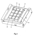
- FIG. 2 Another embodiment of a dental restoration device according to the invention can be seen from Fig. 2.
- the chips 12 are mounted closely adjacent and here too is one first group 22 from the semiconductor radiation sources 24 and a second group 20 of semiconductor radiation sources 26 is provided.
- the Dental restoration device according to the invention With the control device according to the invention are first the semiconductor radiation sources 24 switched on, the Dental restoration device according to the invention in immediate Neighborhood with the surface of the restoration part to be hardened has been brought. In this state the first catalyst activates and leads to pre-curing the photopolymerizable mass.
- post-processing may be carried out, if this is considered necessary. Also, for example another layer of dental restoration material be applied.
- the semiconductor radiation sources become the second Group 20 turned on and there is a hardening performed.
- FIG 3 shows the emission of the dental restoration device according to the invention in the state when all semiconductor radiation sources are switched on. It is a first maximum 30 and a second maximum 32 can be seen, the light intensity the second maximum 32, which is around 420 nm, is significantly higher.
Abstract
Description
Die Erfindung betrifft ein dentales Lichtgerät, welches nicht nur zum Aushärten von photopolymerisierbaren Dentalmaterialien geeignet ist, sondern z.B. auch zum Bleichen von Zähnen oder als Diagnostikgerät für Karies eingesetzt werden kann. Auch andere hier nicht erwähnte Therapiemöglichkeiten können mit dem dentalen Lichtgerät verwirklicht werden. Im folgenden wird das dentale Lichtgerät auch als Dentalrestaurationsvorrichtung bezeichnet.The invention relates to a dental light device, which is not only for curing photopolymerizable dental materials is suitable, e.g. also for bleaching teeth or can be used as a diagnostic device for caries. Also other therapy options not mentioned here can also be used the dental light device can be realized. The following will the dental light device also as a dental restoration device designated.
Dentalrestaurationsvorrichtungen werden u.a. im Dentalbereich eingesetzt, um eine Lichtpolymerisation lichthärtbarer Kunststoffe vorzunehmen. Um eine große Leuchtdichte zu erreichen, werden regelmäßig energiereiche Lichtquellen eingesetzt, wie Halogen-Glühlampen, Xenon-Blitzlampen oder gar Hochspannungs-Entladungslampen. Die letztgenannten Lampen weisen zwar eine ausgesprochen hohe Lichtstärke und damit eine entsprechend hohe Leuchtdichte auf. Jedoch beträgt die Betriebsspannung mindestens 3,5 kV, und es ist ein entsprechendes Vorschaltgerät erforderlich, so dass derartige Lampen für die Anwendung in zahnärztlichen Praxen - mindestens soweit Handgeräte betroffen sind - ungeeignet sind.Dental restoration devices are i.a. in the dental field used to light polymerize light-curable plastics make. To achieve a high luminance, are regularly used high-energy light sources, such as Halogen incandescent lamps, xenon flash lamps or even high-voltage discharge lamps. The latter lamps have one exceptionally high light intensity and therefore a corresponding one high luminance. However, the operating voltage is at least 3.5 kV and it is a corresponding ballast required such lamps for use in dental practices - at least as far as hand tools are concerned are - are unsuitable.
Es sind zahlreiche Versuche unternommen worden, die Leuchtdichte von Beleuchtungsvorrichtungen für Dentalrestaurationsvorrichtungen zu verbessern, um eine vollständige Durchhärtung auch tiefliegender Schichten rasch zu erzielen. Bislang bekannte, übliche Beleuchtungsvorrichtungen mit einer Beleuchtungsstärke von beispielsweise 150 mW/cm2 führen zwar bei entsprechend langer Lichtbeaufschlagung des zu polymerisierenden Kunststoffteils zu einer guten Oberflächenhärte. Tiefer liegende Schichten werden jedoch nicht oder nur unvollständig durchgehärtet. Es entsteht ein Härtegradient, der dazu führt, dass tieferliegende, mittlere Bereiche noch eher weich verbleiben oder später durchhärten als Oberflächenbereiche.Numerous attempts have been made to improve the luminance of lighting devices for dental restoration devices in order to achieve complete curing of deep-lying layers quickly. Previously known, conventional lighting devices with an illuminance of, for example, 150 mW / cm 2 lead to good surface hardness when the plastic part to be polymerized is exposed to light for a correspondingly long time. However, deeper layers are not or only incompletely hardened. A hardness gradient is created, which means that lower-lying, middle areas remain soft or harden later than surface areas.
Die bekannten Beleuchtungsvorrichtungen führen zu Restaurationsergebnissen, die teilweise mit Randspaltenproblemen behaftet sind. Die bekannten lichthärtenden Kunststoffe schrumpfen leicht während des Härtens. Mit den bekannten Beleuchtungsvorrichtungen entsteht die Durchhärtung zunächst im oberen/äußeren Bereich des Materials. Die nachfolgende Durchhärtung der tieferliegenden, zentralen Bereiche führt zur Kontraktion und damit zur Randspaltenbildung.The known lighting devices lead to restoration results, some of which have marginal column problems are. The known light-curing plastics are shrinking easy during curing. With the known lighting devices The hardening initially occurs in the upper / outer Area of material. The subsequent hardening the lower, central areas leads to contraction and thus for the formation of marginal gaps.
Ferner sind auch seit längerem Beleuchtungsvorrichtungen bekannt geworden, die mit Halbleiter-Strahlungsquellen wie LEDs arbeiten. Beispielsweise ist aus der DE-GM 295 11 927 ein Lichthärtgerät bekannt geworden, dass eine im blauen Spektralbereich emittierende Leuchtdiode verwendet, die von einer Batterie oder einem Akkumulator gespeist wird.Furthermore, lighting devices have also been known for some time become those with semiconductor radiation sources like LEDs work. For example, from DE-GM 295 11 927 Light curing device has become known to be in the blue spectral range emitting light emitting diode used by a battery or an accumulator is fed.
Ferner ist es auch bereits vorgeschlagen worden, mehrere LEDs für die Speisung des Lichtleiterstabs zu verwenden. Hierdurch lässt sich die Lichtabgabe des Lichthärtgeräts verbessern. Unabhängig davon, ob die LEDs als Modul, also in einem gemeinsamen Kunststoffgehäuse, oder als Einzel-LEDs, also jeweils in einem Kunststoffgehäuse angeordnet sind und strahlen, ist ihre Lichtabgabe begrenzt. Die Kunststoffumhüllung wirkt nicht nur elektrisch isolierend, sondern dämmt auch die Wärmeabgabe, so dass auch bei Kühlung des Kunststoffgehäuses von aussen eine bestimmte Leistungsdichte des je lichtaussendenden Chips nicht überschritten werden sollte.Furthermore, it has also already been proposed to use several LEDs to be used for feeding the light guide rod. hereby the light output of the light curing device can be improved. Independently whether the LEDs as a module, i.e. in a common Plastic housing, or as individual LEDs, so each in are arranged in a plastic housing and shine is theirs Limited light output. The plastic wrapper doesn't just work electrically insulating, but also insulates heat emission, so that even when cooling the plastic housing from the outside certain power density of the light-emitting chip is not should be exceeded.
Ferner ist es bereits vorgeschlagen worden, als Halbleiter-Strahlungsquelle eine lichtemittierende Diode zu verwenden, die Strahlung im Bereich sichtbaren oder ultravioletten Lichts abgeben soll. Dies ist jedoch mit Nachteilen verbunden. So hat sich bei Untersuchungen herausgestellt, dass gerade bei hellen Materialien Farbänderungen durch die Aushärtung auftreten. Andererseits erlauben die bisher bekannten Systeme nicht die Verwendung von weißen Photoinitiatoren.Furthermore, it has already been proposed as a semiconductor radiation source to use a light emitting diode the radiation in the range of visible or ultraviolet light should give up. However, this has disadvantages. So had investigations have shown that especially in bright Materials color changes occur due to curing. On the other hand, the previously known systems do not allow that Use of white photoinitiators.
Zudem ist die Tendenz zur Randspaltenbildung bei den bekannten Systemen immer noch ungebrochen.In addition, there is a tendency to form marginal gaps in the known ones Systems still unbroken.
Daher liegt der Erfindung die Aufgabe zugrunde, ein Lichtgerät für Dentalzwecke gemäß dem Oberbegriff von Anspruch 1 zu schaffen, das die Neigung zur Randspaltenbildung lichthärtbarer Massen reduziert und dennoch kostengünstig herzustellen und flexibel einzusetzen ist.The invention is therefore based on the object of a light device for dental purposes according to the preamble of claim 1 create the light-curable tendency to form marginal gaps Reduced masses and yet inexpensive to manufacture and is flexible to use.
Diese Aufgabe wird erfindungsgemäß durch Anspruch 1 gelöst. Vorteilhafte Weiterbildungen ergeben sich aus den Unteransprüchen.This object is achieved by claim 1. Advantageous further developments result from the subclaims.
Die erfindungsgemäße Dentalrestaurationsvorrichtung gemäß Anspruch 1 weist eine Halbleiter-Strahlungsquelle mit einem Emissionsspektrum mit mindestens 2 Maxima auf. Erfindungsgemäß sind die beiden Maxima deutlich voneinander getrennt. Damit wird erstmals die Möglichkeit eröffnet, Kunststoffmaterialien zu verwenden, die zwei verschiedene Katalysatorsysteme aufweisen, die nacheinander aushärten. Erfindungsgemäß ist es hiermit möglich, die Tendenz zur Randspaltenbildung zu reduzieren.The dental restoration device according to the invention 1 has a semiconductor radiation source with a Emission spectrum with at least 2 maxima. According to the invention the two maxima are clearly separated from each other. In order to for the first time the opportunity is opened to plastic materials to use, which have two different catalyst systems, which harden one after the other. It is hereby according to the invention possible to reduce the tendency to form marginal gaps.
Erfindungsgemäß besonders günstig ist es, daß Strahlungsquellen zweier verschiedener Wellenlängen zur Aushärtung gleichzeitig verwendet werden können, um alle in Dentalmaterialien verwendeten Initiatoren von 400 bis 500 nm anzuregen.According to the invention, it is particularly favorable that radiation sources two different wavelengths for curing at the same time can be used to all in dental materials used initiators from 400 to 500 nm.
Durch die Anregung einer Halbleiter-Strahlungsquelle mit einem Emissionsspektrum, dessen Maximum der spektralen Empfindlichkeit des ersten Katalysators entspricht, wird eine Voraushärtung vorgenommen. Bei Bedarf kann dann bereits eine Nachbearbeitung vorgenommen werden, nachdem das Kunststoffmaterial in diesem Zustand eine erhöhte Viskosität aufweist, aber noch verformbar ist. Durch Aktivierung der anderen Strahlungsquelle mit einem Emissionsspektrum mit einem Maximum, das von dem ersten Maximum deutlich verschieden ist und bevorzugt eine kurze Wellenlänge aufweist, läßt sich dann ein zweiter Katalysator aktivieren, dessen Empfindlichkeitsmaximum dem zweiten Maximum entspricht. Bevorzugt liegt dieses bei 420 nm. Durch die Aktivierung dieses Katalysators läßt sich das Kunststoffmaterial fertig durchhärten.By exciting a semiconductor radiation source with a Emission spectrum, the maximum of the spectral sensitivity of the first catalyst corresponds to pre-curing performed. If necessary, post-processing can then be carried out be made after the plastic material in this state has an increased viscosity, but still is deformable. By activating the other radiation source with an emission spectrum with a maximum that of the first Maximum is significantly different and preferably a short one Wavelength, then a second catalyst can be activate whose sensitivity maximum is the second maximum equivalent. This is preferably 420 nm. By activation The plastic material can be this catalyst finish hardening.
Überraschend stellt sich bei dieser Lösung auch ohne Nachbearbeitung und besonderen Maßnahmen eine geringere Neigung zur Randspaltenbildung ein. Durch die bislang übliche Lichthärtung mittels einer Strahlungsquelle bei Verwendung eines Katalysators erfolgt die Härtung regelmäßig so, dass zunächst die dünneren Randschichten und die Oberflächenschichten der Dentalrestauration gehärtet werden. Anschließend hieran werden die durch die Eindringtiefe der Strahlung schlechter erreichbaren tiefer liegenden und zentralen Schichten des Dentalmaterials gehärtet. Durch die Kontraktion dieser Bereiche werden Randspalten erzeugt, zumal die Oberflächenbereiche und Randbereiche der Dentalrestauration dann regelmäßig bereits eine höhere Festigkeit aufweisen als der noch weichere noch tief liegende Mittenbereich.Surprisingly, this solution is also possible without post-processing and special measures a lower tendency to Formation of marginal gaps. Due to the usual light curing by means of a radiation source when using a catalyst Hardening takes place regularly so that the thinner ones first Edge layers and the surface layers of the dental restoration be hardened. Then the more difficult to reach due to the penetration depth of the radiation deeper and central layers of the dental material hardened. By contraction of these areas, marginal gaps become generated, especially since the surface areas and edge areas of the dental restoration then regularly one have higher strength than the even softer still deep lying center area.
Erfindungsgemäß ist demgegenüber die mit der Härtung einhergehende Schrumpfung in einem Zustand vorgesehen, in dem das Material weder im Randbereich noch im Mittenbereich bereits vollständig hart ist. Hierdurch überwiegen die Adhäsionskräfte deutlich die der Verformung entgegenstehenden Kräfte, so dass die Schrumpfverformung kurzerhand darin besteht, dass sich die Schichtstärke des Restaurationsteils etwas reduziert. Dies ist unproblematisch und kann bei Bedarf auch durch das Auftragen zusätzlicher Schichten oder eine vorab vorgenommene erhöhte Schichtstärke kompensiert werden.In contrast, according to the invention is that associated with the hardening Shrinkage is provided in a condition where the material neither in the edge area nor in the middle area is completely hard. As a result, the adhesive forces predominate clearly the forces opposing the deformation, so that the shrinkage deformation is simply that the Slightly reduced layer thickness of the restoration part. This is unproblematic and can also be applied if necessary additional layers or a pre-increased Layer thickness can be compensated.
Es versteht sich, dass bei Bedarf die Möglichkeit besteht, die Auswahl von Katalysator und Emissionsmaximum je aufeinander abzustimmen und in weiten Bereichen an die Erfordernisse anzupassen. So kann bei Bedarf ein recht langwelliges Emissionsmaximum für die erste Strahlungsquelle realisiert sein, und der Katalysator für die erste Strahlungsquelle kann so ein Emissionsmaximum beispielsweise bei mehr als 500 nm aufweisen. Die Dentalmaterialien können sowohl mit Licht als auch zusätzlich mit Wärme ausgehärtet bzw. nachgehärtet werden.It goes without saying that, if necessary, there is the possibility of Selection of catalytic converter and emission maximum for each other to coordinate and adapt to the needs in wide areas. So, if necessary, a quite long-wave emission maximum be realized for the first radiation source, and the catalyst for the first radiation source can be one Have emission maximum, for example, at more than 500 nm. The dental materials can both with light as well as additionally be cured with heat or post-cured.
Erfindungsgemäß sind insofern dualhärtende Systeme möglich.To this extent, dual-curing systems are possible according to the invention.
In vorteilhafter Ausgestaltung der Erfindung wird das Lichtgerät mit den Strahlungsquellen direkt am Zahn aufgesetzt. In besonders günstiger Ausgestaltung ist eine Anschlusstülle (ein Überzug) vorgesehen, der gegen den Zahn elastisch anliegen kann und dafür sorgt, dass das emittierte Licht vollständig zur Dentalrestauration gelangt. Durch diese Ausgestaltung ist die Härtezeit exakt per reproduzierbar, nachdem nicht nur die vom Lichthärtgerät abgegebene Lichtleistung, sondern die zur Dentalrestauration gelangende Lichtleistung festlegbar ist.In an advantageous embodiment of the invention, the light device with the radiation sources placed directly on the tooth. In A particularly advantageous embodiment is a connection grommet (a Cover) is provided, which lie elastically against the tooth can and ensures that the emitted light is complete to dental restoration. This configuration is the hardening time can be reproduced exactly by not only the from the light curing device emitted light output, but the for Dental restoration light output can be determined.
Weitere Vorteile, Einzelheiten und Merkmale ergeben sich aus der nachstehenden Beschreibung zweier Ausführungsbeispiele anhand der Zeichnung.Further advantages, details and features result from the following description of two exemplary embodiments based on the drawing.
- Fig. 1Fig. 1
- eine Ansicht eines Details einer erfindungsgemäßen Dentalrestaurationsvorrichtung, nämlich eines Basiskörpers mit integrierten Strahlungswellen in perspektivischer Darstellung;2 shows a view of a detail of a dental restoration device according to the invention, namely a basic body with integrated radiation waves in perspective Presentation;
- Fig. 2Fig. 2
- eine weitere Ausführungsform einer erfindungsgemäßen Dentalrestaurationsvorrichtung, unter Darstellung einer modifizierten Ausgestaltung der Strahlungsquellen; unda further embodiment of an inventive Dental restoration device, showing a modified configuration of the radiation sources; and
- Fig. 3Fig. 3
- eine Darstellung eines Spektrums der Strahlungsquellen einer erfindungsgemäßen Dentalrestaurationsvorrichtung.a representation of a spectrum of the radiation sources a dental restoration device according to the invention.
Eine erfindungsgemäße Dentalrestaurationsvorrichtung weist einen
Basiskörper 10 auf, der mit einer Mehrzahl von LED-Chips
12 an seiner Oberseite 14 bestückt ist. Die LED-Chips 12 sind
je am Grunde von Mulden 16 befestigt und gegenüber der Oberfläche
18 versenkt. In dem dargestellten Ausführungsbeispiel
sind 9 Chips 12 vorgesehen. Durch die Versenkung der Chips 12
in Mulden ergeben sich Mikroreflektoren, die die Lichtausbeute
erhöhen.A dental restoration device according to the invention has one
Ein Teil der LED-Chips weist ein Emissionsmaximum von 470 nm. Ein weiterer Teil der LED-Chips weist ein Emissionsmaximum von 420 nm. Die Teile sind je zu Gruppen von LED-Chips zusammengeschaltet, wobei die Gruppen an je an einen Ausgang einer Steuervorrichtung angeschlossen sind und getrennt ansteuerbar sind.Some of the LED chips have an emission maximum of 470 nm. Another part of the LED chips has an emission maximum of 420 nm. The parts are connected to groups of LED chips, the groups each at an output of a Control device are connected and separately controllable are.
Die Chips 12 der ersten Gruppe 22 bilden Halbleiter-Strahlungsquellen
24 mit einem Emissionsmaximum von 470 nm, und die
Chips 12 der zweiten Gruppe 20 bilden Halbleiter-Strahlungsquellen
26 mit einem Emissionsmaximum von 420 nm.The
Über an sich bekannte Bonddrähte 28 sind die einzelnen Chips
12 jeder Gruppe teils in Parallelschaltung, teils in Reihenschaltung
mit Sammelschienen 29 verbunden.The individual chips are connected via known
Die Sammelschienen 29 sind über nicht dargestellte separate
Versorgungsleitungen angeschlossen und mit einer nicht
dargestellten Steuervorrichtung verbunden.The
Eine weitere Ausführungsform einer erfindungsgemäßen Dentalrestaurationsvorrichtung
ist aus Fig. 2 ersichtlich. Hier sind
die Chips 12 eng benachbart montiert und auch hier ist eine
erste Gruppe 22 von den Halbleiter-Strahlungsquellen 24 und
eine zweite Gruppe 20 von Halbleiter-Strahlungsquellen 26 vorgesehen.Another embodiment of a dental restoration device according to the invention
can be seen from Fig. 2. Here are
the
Mit der erfindungsgemäßen Steuervorrichtung werden zunächst
die Halbleiter-Strahlungsquellen 24 eingeschaltet, wobei die
erfindungsgemäße Dentalrestaurationsvorrichtung in unmittelbarer
Nachbarschaft mit der Oberfläche des zu härtenden Restaurationsteils
gebracht worden ist. In diesem Zustand wird
der erste Katalysator aktiviert und führt zur Voraushärtung
der photopolymerisierbaren Masse.With the control device according to the invention are first
the
Anschließend hieran wird ggf. eine Nachbearbeitung vorgenommen, wenn dies als erforderlich angesehen wird. Auch kann beispielsweise auch eine weitere Schicht Dentalrestaurationsmaterial aufgetragen werden.Subsequent to this, post-processing may be carried out, if this is considered necessary. Also, for example another layer of dental restoration material be applied.
Hieraufhin werden die Halbleiter-Strahlungsquellen der zweiten
Gruppe 20 eingeschaltet, und es wird eine Durchhärtung
vorgenommen.Thereupon the semiconductor radiation sources become the
Es versteht sich, dass eine beliebige Verteilung der Strahlungsquellen im Rahmen der Erfindung möglich ist.It is understood that any distribution of the radiation sources is possible within the scope of the invention.
Fig. 3 zeigt die Emission der erfindungsgemäßen Dentalrestaurationsvorrichtung in dem Zustand, wenn alle Halbleiter-Strahlungsquellen eingeschaltet sind. Es ist ein erstes Maximum 30 und eine zweites Maximum 32 ersichtlich, wobei die Lichtintensität des zweiten Maximums 32, das bei etwa 420 nm liegt, deutlich höher ist.3 shows the emission of the dental restoration device according to the invention in the state when all semiconductor radiation sources are switched on. It is a first maximum 30 and a second maximum 32 can be seen, the light intensity the second maximum 32, which is around 420 nm, is significantly higher.
Claims (16)
Applications Claiming Priority (2)
| Application Number | Priority Date | Filing Date | Title |
|---|---|---|---|
| DE10125340A DE10125340B4 (en) | 2001-05-23 | 2001-05-23 | Dental light device |
| DE10125340 | 2001-05-23 |
Publications (2)
| Publication Number | Publication Date |
|---|---|
| EP1260193A2 true EP1260193A2 (en) | 2002-11-27 |
| EP1260193A3 EP1260193A3 (en) | 2003-05-21 |
Family
ID=7685992
Family Applications (1)
| Application Number | Title | Priority Date | Filing Date |
|---|---|---|---|
| EP02008013A Withdrawn EP1260193A3 (en) | 2001-05-23 | 2002-04-10 | Dental light device |
Country Status (4)
| Country | Link |
|---|---|
| EP (1) | EP1260193A3 (en) |
| JP (1) | JP3629475B2 (en) |
| CA (1) | CA2383181A1 (en) |
| DE (1) | DE10125340B4 (en) |
Cited By (4)
| Publication number | Priority date | Publication date | Assignee | Title |
|---|---|---|---|---|
| DE102007011637A1 (en) * | 2007-03-09 | 2008-09-18 | Ivoclar Vivadent Ag | Light emitting device |
| US8113831B2 (en) | 2006-07-31 | 2012-02-14 | Ivoclar Vivadent Ag | Hand-held light curing device |
| EP2465466A1 (en) * | 2010-12-20 | 2012-06-20 | Ivoclar Vivadent AG | Handheld dental device |
| WO2024051274A1 (en) * | 2022-09-09 | 2024-03-14 | 桂林市啄木鸟医疗器械有限公司 | Light-emitting module, light source, and dental light-curing machine |
Families Citing this family (5)
| Publication number | Priority date | Publication date | Assignee | Title |
|---|---|---|---|---|
| DE10155034B4 (en) * | 2001-11-09 | 2006-03-09 | Ivoclar Vivadent Ag | A light curing apparatus and method of polymerizing polymerizable compositions |
| DE102006015336B4 (en) * | 2006-04-03 | 2015-05-07 | Ivoclar Vivadent Ag | A semiconductor radiation source, a semiconductor radiation source light curing device, a semiconductor radiation source illumination device, and a semiconductor radiation source illumination device |
| EP2489344B1 (en) | 2011-02-15 | 2021-03-24 | Ivoclar Vivadent AG | Dental material based on an anti-microbial compound |
| EP2801335B1 (en) | 2013-05-07 | 2018-03-14 | Ivoclar Vivadent AG | Syringe |
| CN105338948B (en) | 2013-06-27 | 2019-02-01 | 义获嘉伟瓦登特股份有限公司 | Nanocrystal zirconium oxide and its processing method |
Citations (1)
| Publication number | Priority date | Publication date | Assignee | Title |
|---|---|---|---|---|
| DE29511927U1 (en) | 1995-07-24 | 1997-01-09 | Thera Ges Fuer Patente | Light curing unit |
Family Cites Families (8)
| Publication number | Priority date | Publication date | Assignee | Title |
|---|---|---|---|---|
| DE3404904C2 (en) * | 1984-02-11 | 1986-01-16 | Kulzer & Co GmbH, 6393 Wehrheim | Process for the manufacture of orthodontic devices and appliances |
| US5420768A (en) * | 1993-09-13 | 1995-05-30 | Kennedy; John | Portable led photocuring device |
| DE29511297U1 (en) * | 1995-07-12 | 1995-12-14 | Sanitaetshaus Korn | Brake retrofit kit for wheels |
| EP0780103A3 (en) * | 1995-12-22 | 1997-12-03 | Heraeus Kulzer GmbH | Irradiation apparatus |
| DE19721311C1 (en) * | 1997-05-21 | 1998-12-03 | Eka Ges Fuer Medizinisch Tech | Irradiation device for the polymerization of light-curing plastics |
| EP1031326A1 (en) * | 1999-02-05 | 2000-08-30 | Jean-Michel Decaudin | Device for photo-activation of photosensitive composite materials especially in dentistry |
| EP1090607A1 (en) * | 1999-10-08 | 2001-04-11 | Mectron S.R.L. | A dental handpiece for the polymerization of photosetting compounds or resins |
| IT1321003B1 (en) * | 2000-05-03 | 2003-12-18 | Mcm Srl | METHOD FOR THE REMOVABLE LOCKING OF SLABS TO CORRESPONDING FORMEAS ADHESIVE TAPE CLAMP AND DEVICE THAT IMPLEMENTS SUCH |
-
2001
- 2001-05-23 DE DE10125340A patent/DE10125340B4/en not_active Expired - Fee Related
-
2002
- 2002-04-10 EP EP02008013A patent/EP1260193A3/en not_active Withdrawn
- 2002-04-24 CA CA002383181A patent/CA2383181A1/en not_active Abandoned
- 2002-05-23 JP JP2002149882A patent/JP3629475B2/en not_active Expired - Fee Related
Patent Citations (1)
| Publication number | Priority date | Publication date | Assignee | Title |
|---|---|---|---|---|
| DE29511927U1 (en) | 1995-07-24 | 1997-01-09 | Thera Ges Fuer Patente | Light curing unit |
Cited By (5)
| Publication number | Priority date | Publication date | Assignee | Title |
|---|---|---|---|---|
| US8113831B2 (en) | 2006-07-31 | 2012-02-14 | Ivoclar Vivadent Ag | Hand-held light curing device |
| DE102007011637A1 (en) * | 2007-03-09 | 2008-09-18 | Ivoclar Vivadent Ag | Light emitting device |
| EP2465466A1 (en) * | 2010-12-20 | 2012-06-20 | Ivoclar Vivadent AG | Handheld dental device |
| EP2465467A1 (en) * | 2010-12-20 | 2012-06-20 | Ivoclar Vivadent AG | Hand-controlled dental device |
| WO2024051274A1 (en) * | 2022-09-09 | 2024-03-14 | 桂林市啄木鸟医疗器械有限公司 | Light-emitting module, light source, and dental light-curing machine |
Also Published As
| Publication number | Publication date |
|---|---|
| EP1260193A3 (en) | 2003-05-21 |
| DE10125340B4 (en) | 2004-08-05 |
| CA2383181A1 (en) | 2002-11-23 |
| DE10125340A1 (en) | 2002-12-05 |
| JP3629475B2 (en) | 2005-03-16 |
| JP2002360614A (en) | 2002-12-17 |
Similar Documents
| Publication | Publication Date | Title |
|---|---|---|
| DE102006015336B4 (en) | A semiconductor radiation source, a semiconductor radiation source light curing device, a semiconductor radiation source illumination device, and a semiconductor radiation source illumination device | |
| DE102004063824B4 (en) | Light-emitting diode module with anti-parallel diode chip | |
| DE10258193B4 (en) | Method for producing light-emitting diode light sources with luminescence conversion element | |
| DE10135306A1 (en) | Process for the production of devices that emit light of the same color temperature | |
| DE10125341B4 (en) | Irradiation device and light curing device | |
| EP0879582A2 (en) | Light radiation device for hardening of light-curing resins | |
| DE102005053218A1 (en) | LED device and method of making the same | |
| EP1260193A2 (en) | Dental light device | |
| DE102005053217A1 (en) | Method of manufacturing an LED device | |
| EP3308740B1 (en) | Light curing device for dental restoration materials | |
| DE112018000656T5 (en) | LED assembly and method of making the same | |
| EP2454765A1 (en) | Light-emitting diode and method for producing a light-emitting diode | |
| DE10104579A1 (en) | light curing | |
| DE102014113844A1 (en) | Method for producing an optoelectronic component and optoelectronic component | |
| DE102016124873B4 (en) | White light source and method for producing a white light source | |
| DE10125343C2 (en) | lighting device | |
| DE102013204293A1 (en) | Production of an optoelectronic component | |
| DE102010031732A1 (en) | Optoelectronic component | |
| EP3106123B1 (en) | Dental light-curing device | |
| EP2396158B1 (en) | Method and mould for producing an led light | |
| DE102014205470B4 (en) | Lighting device with CoB range | |
| DE102016125022A1 (en) | MANUFACTURE OF LIGHTING DEVICES | |
| DE10155034B4 (en) | A light curing apparatus and method of polymerizing polymerizable compositions | |
| WO2014086784A1 (en) | Light-emitting diode comprising a plurality of luminescent regions | |
| WO2016071308A1 (en) | Optoelectronic component and method for the production thereof |
Legal Events
| Date | Code | Title | Description |
|---|---|---|---|
| PUAI | Public reference made under article 153(3) epc to a published international application that has entered the european phase |
Free format text: ORIGINAL CODE: 0009012 |
|
| AK | Designated contracting states |
Kind code of ref document: A2 Designated state(s): AT BE CH CY DE DK ES FI FR GB GR IE IT LI LU MC NL PT SE TR |
|
| AX | Request for extension of the european patent |
Free format text: AL;LT;LV;MK;RO;SI |
|
| PUAL | Search report despatched |
Free format text: ORIGINAL CODE: 0009013 |
|
| AK | Designated contracting states |
Designated state(s): AT BE CH CY DE DK ES FI FR GB GR IE IT LI LU MC NL PT SE TR |
|
| AX | Request for extension of the european patent |
Extension state: AL LT LV MK RO SI |
|
| 17P | Request for examination filed |
Effective date: 20031024 |
|
| AKX | Designation fees paid |
Designated state(s): AT BE CH CY DE DK ES FI FR GB GR IE IT LI LU MC NL PT SE TR |
|
| 17Q | First examination report despatched |
Effective date: 20050214 |
|
| STAA | Information on the status of an ep patent application or granted ep patent |
Free format text: STATUS: THE APPLICATION HAS BEEN WITHDRAWN |
|
| 18W | Application withdrawn |
Effective date: 20180905 |
|
| RIC1 | Information provided on ipc code assigned before grant |
Ipc: A61C 19/00 20060101ALI20020902BHEP Ipc: A61C 13/15 20060101AFI20020902BHEP |