EP1259851B1 - Mikrolinsen-folie mit zusammengesetztem, schwebendem bild - Google Patents
Mikrolinsen-folie mit zusammengesetztem, schwebendem bild Download PDFInfo
- Publication number
- EP1259851B1 EP1259851B1 EP00941580A EP00941580A EP1259851B1 EP 1259851 B1 EP1259851 B1 EP 1259851B1 EP 00941580 A EP00941580 A EP 00941580A EP 00941580 A EP00941580 A EP 00941580A EP 1259851 B1 EP1259851 B1 EP 1259851B1
- Authority
- EP
- European Patent Office
- Prior art keywords
- sheeting
- radiation
- image
- microlens
- images
- Prior art date
- Legal status (The legal status is an assumption and is not a legal conclusion. Google has not performed a legal analysis and makes no representation as to the accuracy of the status listed.)
- Expired - Lifetime
Links
Images


Classifications
-
- G—PHYSICS
- G02—OPTICS
- G02B—OPTICAL ELEMENTS, SYSTEMS OR APPARATUS
- G02B5/00—Optical elements other than lenses
- G02B5/12—Reflex reflectors
- G02B5/126—Reflex reflectors including curved refracting surface
- G02B5/128—Reflex reflectors including curved refracting surface transparent spheres being embedded in matrix
-
- G—PHYSICS
- G02—OPTICS
- G02B—OPTICAL ELEMENTS, SYSTEMS OR APPARATUS
- G02B30/00—Optical systems or apparatus for producing three-dimensional [3D] effects, e.g. stereoscopic images
- G02B30/50—Optical systems or apparatus for producing three-dimensional [3D] effects, e.g. stereoscopic images the image being built up from image elements distributed over a 3D volume, e.g. voxels
- G02B30/56—Optical systems or apparatus for producing three-dimensional [3D] effects, e.g. stereoscopic images the image being built up from image elements distributed over a 3D volume, e.g. voxels by projecting aerial or floating images
Definitions
- the present invention relates to sheeting that provides one or more composite images that are perceived by an observer to be suspended in space relative to the sheeting, and in which the perspective of the composite image changes with the viewing angle.
- Sheeting materials having a graphic image or other mark have been widely used, particularly as labels for authenticating an article or document.
- sheetings such as those described in U.S. Patent Nos. 3,154,872 ; 3,801,183 ; 4,082,426 ; and 4,099,838 have been used as validation stickers for vehicle license plates, and as security films for driver's licenses, government documents, tape cassettes, playing cards, beverage containers, and the like.
- Other uses include graphics applications for identification purposes such as on police, fire or other emergency vehicles, in advertising and promotional displays and as distinctive labels to provide brand enhancement.
- the images formed in the retroreflective sheeting of Galanos can be viewed if, and only if, the sheeting is viewed from the same angle at which the laser irradiation was directed at the sheeting. That means, in different terms, that the image is only viewable over a very limited observation angle. For that and other reasons, there has been a desire to improve certain properties of such a sheeting.
- Gabriel Lippman invented a method for producing a true three-dimensional image of a scene in lenticular media having one or more photosensitive layers. That process, known as integral photography, is also described in De Montebello, "Processing and Display of Three-Dimensional Data II" in Proceedings of SPIE, San Diego, 1984 .
- a photographic plate is exposed through an array of lenses (or “lenslets"), so that each lenslet of the array transmits a miniature image of the scene being reproduced, as seen from the perspective of the point of the sheet occupied by that lenslet, to the photosensitive layers on a photographic plate.
- an observer looking at the composite image on the plate through the lenslet array sees a three-dimensional representation of the scene photographed.
- the image may be in black and white or in color, depending on the photosensitive materials used.
- the three-dimensional representation produced is pseudoscopic. That is, the perceived depth of the image is inverted so that the object appears "inside out.”
- This is a major disadvantage, because to correct the image it is necessary to achieve two optical inversions.
- These methods are complex, involving multiple exposures with a single camera, or multiple cameras, or multi-lens cameras, to record a plurality of views of the same object, and require extremely accurate registration of multiple images to provide a single three-dimensional image. Further, any method that relies on a conventional camera requires the presence of a real object before the camera.
- a further disadvantage of integral photography is that the composite image must be illuminated from the viewing side to form a real image that may be viewed.
- US-A-5,712,731 describes a security device for security documents such as bank notes and credit cards comprising a regular two dimensional array of substantially identical printed microimages.
- US-A-3,801,183 describes a retro-reflective film including a layer of microspheres.
- the present invention provides a microlens sheeting having a composite image that appears to be suspended above or below the sheeting.
- These suspended images are referred to for convenience as floating images, and they can be located above or below the sheeting (either as two or three-dimensional images), or can be a three-dimensional image that appears above, in the plane of, and below the sheeting.
- the images can be in black and white or in color, and can appear to move with the observer. Unlike some holographic sheetings, imaged sheeting of the present invention cannot be used to create a replica of itself. Additionally, the floating image(s) can be observed by a viewer with the unaided eye.
- the inventive sheeting having a composite image as described may be used in a variety of applications such as securing tamperproof images in passports, ID badges, event passes, affinity cards, product identification formats and advertising promotions for verification and authenticity, brand enhancement images which provide a floating or sinking or a floating and sinking image of the brand, identification presentation images in graphics applications such as emblems for police, fire or other emergency vehicles; information presentation images in graphics applications such as kiosks, night signs and automotive dashboard displays; and novelty enhancement through the use of composite images on products such as business cards, hang-tags, art, shoes and bottled products.
- the present invention further provides a novel means of forming imaged sheeting containing the described composite images.
- a single composite image is formed.
- Embodiments are also disclosed in which two or more composite images are formed, as well as composite images that appear to be both above and below the sheeting.
- Other embodiments could consist of combinations of conventionally printed images and composite images formed by this invention.
- the microlens sheeting of the present invention provides a composite image, provided by individual images associated with a number of the microlenses, that appears to be suspended, or to float, above, in the plane of, and/or below the sheeting.
- microlens sheetings will be described in Part I below, followed by descriptions of the material layers (preferably radiation sensitive material layers) of such sheetings in Part II, radiation sources in Part III, and the imaging process in Part IV.
- material layers preferably radiation sensitive material layers
- Microlens sheeting in which the images of this invention can be formed comprise one or more discrete layers of microlenses with a layer of material (preferably a radiation-sensitive material or coating, as described below) disposed adjacent to one side of the microlens layer or layers.
- a layer of material preferably a radiation-sensitive material or coating, as described below
- Figure 1 shows an "exposed lens" type of microlens sheeting 10 that includes a monolayer of transparent microspheres 12 that are partially embedded in a binder layer 14, which is typically a polymeric material.
- the microspheres are transparent both to the wavelengths of radiation that may be used to image the layer of material, as well as to the wavelengths of light in which the composite image will be viewed.
- the layer of material 16 is disposed at the rear surface of each microsphere, and in the illustrated embodiment typically contacts only a portion of the surface of each of the microspheres 12. This type of sheeting is described in greater detail in U.S. Patent No. 2,326,634 and is presently available from 3M under the designation Scotchlite 8910 series reflective fabric.
- FIG. 2 shows another suitable type of microlens sheeting.
- This microlens sheeting 20 is an "embedded-lens" type of sheeting in which the microsphere lenses 22 are embedded in a transparent protective overcoat 24, which is typically a polymeric material.
- the layer of material 26 is disposed behind the microspheres at the back of a transparent spacer layer 28, which is also typically a polymeric material.
- This type of sheeting is described in greater detail in U.S. Patent No. 3,801,183 , and is presently available from 3M under the designation Scotchlite 3290 series Engineer grade retroreflective sheeting.
- Another suitable type of microlens sheeting is referred to as encapsulated lens sheeting, an example of which is described in U.S. Patent No. 5,064,272 , and presently is available from 3M under the designation Scotchlite 3870 series High Intensity grade retroreflective sheeting.
- Figure 3 shows yet.another suitable type of microlens sheeting.
- This sheeting comprises a transparent plano-convex or aspheric base sheet 30 having first and second broad faces, the second face 32 being substantially planar and the first face having an array of substantially hemi-spheroidal or hemi-aspheroidal microlenses 34.
- the shape of the microlenses and thickness of the base sheet are selected such that collimated light incident to the array is focused approximately at the second face.
- the layer of material 36 is provided on the second face. Sheeting of this kind is described in, for example, U.S. Patent No. 5,254,390 , and is presently available from 3M under the designation 2600 series 3M Secure Card receptor.
- the microlenses of the sheeting preferably have an image forming refractive surface in order for image formation to occur; generally this is provided by a curved microlens surface.
- the microlens will preferably have a uniform index of refraction.
- Other useful materials that provide a gradient refractive index (GRIN) will not necessarily need a curved surface to refract light.
- the microlens surfaces are preferably spherical in nature, but aspherical surfaces are also acceptable.
- the microlenses may have any symmetry, such as cylindrical or spherical, provided real images are formed by the refraction surfaces.
- microlenses themselves can be of discrete form, such as round plano-convex lenslets, round double convex lenslets, rods, microspheres, beads, or cylindrical lenslets.
- Materials from which the microlenses can be formed include glass, polymers, minerals, crystals, semiconductors and combinations of these and other materials. Non-discrete microlens elements may also be used.
- microlenses formed from a replication or embossing process (where the surface of the sheeting is altered in shape to produce a repetitive profile with imaging characteristics) can also be used.
- Microlenses with a uniform refractive index of between 1.5 and 3.0 over the visible and infrared wavelengths are most useful. Suitable microlens materials will have minimal absorption of visible light, and in embodiments in which an energy source is used to image a radiation-sensitive layer the materials should exhibit minimal absorption of the energy source as well.
- the refractive power of the microlens, whether the microlens is discrete or replicated, and regardless of the material from which the microlenses are made, is preferably such that the light incident upon the refracting surface will refract and focus on the opposite side of the microlens. More specifically, the light will be focused either on the back surface of the microlens or on the material adjacent to the microlens.
- the microlenses preferably form a demagnified real image at the appropriate position on that layer. Demagnification of the image by approximately 100 to 800 times is particularly useful for forming images that have good resolution.
- the construction of the microlens sheeting to provide the necessary focusing conditions so that energy incident upon the front surface of the microlens sheeting is focused upon a material layer that is preferably radiation sensitive is described in the U.S. patents referenced earlier in this section.
- Microspheres with diameters ranging from 15 micrometers to 275 micrometers are preferable, though other sized microspheres may be used.
- Good composite image resolution can be obtained by using microspheres having diameters in the smaller end of the aforementioned range for composite images that are to appear to be spaced apart from the microsphere layer by a relatively short distance, and by using larger microspheres for composite images that are to appear to be spaced apart from the microsphere layer by larger distances.
- Other microlens such as plano-convex, cylindrical, spherical or aspherical microlenses having lenslet dimensions comparable to those indicated for the microspheres, can be expected to produce similar optical results.
- a layer of material is provided adjacent to the microlenses.
- Individual images formed in the material associated with a plurality of microlenses when viewed by an observer under reflected or transmitted light, provide a composite image that appears to be suspended, or float, above, in the plane of, and/or below the sheeting.
- the preferred method for providing such images is to provide a radiation sensitive material as the material layer, and to use radiation to alter that material in a desired manner to provide the image.
- the invention is not limited thereby, the remaining discussion of the layer of material adjacent the microlenses will be provided largely in the context of a radiation sensitive material layer.
- Radiation sensitive materials useful for this invention include coatings and films of metallic, polymeric and semiconducting materials as well as mixtures of these.
- a material is "radiation sensitive" if upon exposure to a given level of visible or other radiation the appearance of the material exposed changes to provide a contrast with material that was not exposed to that radiation. The image created thereby could thus be the result of a compositional change, a removal or ablation of the material, a phase change, or a polymerization of the radiation sensitive coating.
- Some radiation sensitive metallic film materials include aluminum, silver, copper, gold, titanium, zinc, tin, chromium, vanadium, tantalum, and alloys of these metals.
- These metals typically provide a contrast due to the difference between the native color of the metal and a modified color of the metal after exposure to the radiation.
- the image may also be provided by ablation, or by the radiation heating the material until an image is provided by optical modification of the material.
- United States Patent 4,743,526 describes heating a metal alloy to provide a color change.
- metallic oxides and metallic suboxides can be used as a radiation sensitive medium.
- Materials in this class include oxide compounds formed from aluminum, iron, copper, tin and chromium.
- Non-metallic materials such as zinc sulfide, zinc selenide, silicon dioxide, indium tin oxide, zinc oxide, magnesium fluoride and silicon can also provide a color or contrast that is useful for this invention.
- Multiple layers of thin film materials can also be used to provide unique radiation sensitive materials. These multilayer materials can be configured to provide a contrast change by the appearance or removal of a color or contrast agent. Exemplary constructions include optical stacks or tuned cavities that are designed to be imaged (by a change in color, for example) by specific wavelengths of radiation.
- cryolite/zinc sulphide Na 3 AlF 6 /ZnS
- Another example is an optical stack composed of chromium/polymer (such as plasma polymerized butadiene)/silicon dioxide/aluminum where the thickness of the layers are in the ranges of 4 nm for chromium, between 20 nm and 60 nm for the polymer, between 20 nm and 60 nm for the silicon dioxide, and between 80 nm and 100 nm for the aluminum, and where the individual layer thicknesses are selected to provide specific color reflectivity in the visible spectrum.
- Thin film tuned cavities could be used with any of the single layer thin films previously discussed.
- a tuned cavity with an approximately 4 nm thick layer of chromium and the silicon dioxide layer of between about 100 nm and 300 nm, with the thickness of the silicon dioxide layer being adjusted to provide an colored imaged in response to specific wavelengths of radiation.
- thermochromic materials which include thermochromic materials.
- Thermochromic describes a material that changes color when exposed to a change in temperature.
- thermochromic materials useful in this invention are described in U.S. Patent No. 4,424,990 , and include copper carbonate, copper nitrate with thiourea, and copper carbonate with sulfur containing compounds such as thiols, thioethers, sulfoxides, and sulfones.
- Other suitable thermochromic compounds are described in U.S. Patent No. 4,121,011 , including hydrated sulfates and nitrides of boron, aluminum, and bismuth, and the oxides and hydrated oxides of boron, iron, and phosphorus.
- the material layer can, but is not required to, be radiation sensitive. Radiation sensitive materials are preferred for ease of manufacturing, however, and thus a suitable radiation source is preferably also used.
- a preferred manner of providing the image patterns on the layer of material adjacent the microlenses is to use a radiation source to image a radiation sensitive material.
- Any energy source providing radiation of the desired intensity and wavelength can be used with the method of the present invention.
- Devices capable of providing radiation having a wavelength of between 200 nm and 11 micrometers are believed to be particularly preferred.
- high peak power radiation sources useful for this invention include excimer flashlamps, passively Q-switched microchip lasers, and Q-switched Neodymium doped-yttrium aluminum garnet (abbreviated Nd:YAG), Neodymium doped-yttrium lithium fluoride (abbreviated Nd:YLF) and Titanium doped-sapphire (abbreviated Ti:sapphire) lasers.
- Nd:YAG Neodymium doped-yttrium aluminum garnet
- Nd:YLF Neodymium doped-yttrium lithium fluoride
- Ti:sapphire Titanium doped-sapphire
- useful radiation sources include devices that give low peak power such as laser diodes, ion lasers, non Q-switched solid state lasers, metal vapor lasers, gas lasers, arc lamps and high power incandescent light sources. These sources are particularly useful when the radiation sensitive medium is imaged by a non-ablative method.
- the energy from the radiation source is directed toward the microlens sheeting material and controlled to give a highly divergent beam of energy.
- the light is controlled by appropriate optical elements, examples of which are shown in Figures 14, 15 , and 16 and described in greater detail below.
- a requirement of this arrangement of optical elements, commonly referred to as an optical train is that the optical train direct light toward the sheeting material with appropriate divergence or spread so as to irradiate the microlens and thus the material layer at the desired angles.
- the composite images of the present invention are preferably obtained by using light spreading devices with numerical apertures (defined as the sine of the half angle of the maximum diverging rays) of greater than or equal to 0.3.
- Light spreading devices with larger numerical apertures produce composite images having a greater viewing angle, and a greater range of apparent movement of the image.
- An examplary imaging process consists of directing collimated light from a laser through a lens toward the microlens sheeting.
- the light is transmitted through a diverging lens with a high numerical aperture (NA) to produce a cone of highly divergent light.
- NA numerical aperture
- a high NA lens is a lens with a NA equal to or greater than 0.3.
- the radiation sensitive coating side of the microspheres is positioned away from the lens, so that the axis of the cone of light (the optical axis) is perpendicular to the plane of the microlens sheeting.
- each individual microlens occupies a unique position relative to the optical axis, the light impinging on each microlens will have a unique angle of incidence relative to the light incident on each other microlens. Thus, the light will be transmitted by each microlens to a unique position on the material layer, and produce a unique image. More precisely, a single light pulse produces only a single imaged dot on the material layer, so to provide an image adjacent each microlens, multiple pulses of light are used to create that image out of multiple imaged dots. For each pulse, the optical axis is located at a new position relative to the position of the optical axis during the previous pulse.
- the lens array consists of multiple small lenses all with high numerical apertures arranged in a planar geometry. When the array is illuminated by a light source, the array will produce multiple cones of highly divergent light, each individual cone being centered upon its corresponding lens in the array. The physical dimensions of the array are chosen to accommodate the largest lateral size of a composite image. By virtue of the size of the array, the individual cones of energy formed by the lenslets will expose the microlensed material as if an individual lens was positioned sequentially at all points of the array while receiving pulses of light. The selection of which lenses receive the incident light occurs by the use of a reflective mask. This mask will have transparent areas corresponding to sections of the composite image that are to be exposed and reflective areas where the image should not be exposed. Due to the lateral extent of the lens array, it is not necessary to use multiple light pulses to trace out the image.
- the portions of the mask that allow energy to pass through will form many individual cones of highly divergent light outlining the floating image as if the image was traced out by a single lens.
- a beam positioning system such as a galvometric xy scanner, can be used to locally illuminate the lens array and trace the composite image on the array. Since the energy is spatially localized with this technique, only a few lenslets in the array are illuminated at any given time. Those lenslets that are illuminated will provide the cones of highly diverging light needed to expose the microlensed material to form the composite image in the sheetings.
- the lens array itself can be fabricated from discrete lenslets or by an etching process to produce a monolithic array of lenses.
- Materials suitable for the lenses are those that are non-absorbing at the wavelength of the incident energy.
- the individual lenses in the array preferably have numerical apertures greater than 0.3 and diameters greater than 30 micrometers but less than 10 mm. These arrays may have antireflection coatings to reduce the effects of back reflections that may cause internal damage to the lens material.
- single lenses with an effective negative focal length and dimensions equivalent to the lens array may also be used to increase the divergence of the light leaving the array.
- Shapes of the individual lenslets in a monolithic array are chosen to have a high numerical aperture and provide a large fill factor of approximately greater than 60%.
- Figure 4 is a graphical schematic representation of divergent energy impinging on a microlens sheeting.
- the portion of the material layer on or in which an image I is formed is different for each microlens, because each microlense "sees" the incoming energy from a different perspective.
- a unique image is formed in the material layer associated with each microlens.
- a full or partial image of the object will be present in the radiation sensitive material behind each microsphere.
- the extent to which the actual object is reproduced as an image behind a microsphere depends on the energy density incident upon the microsphere. Portions of an extended object may be distant enough from a region of microlenses that the energy incident upon those microspheres has an energy density lower than the level of radiation required to modify that material.
- a spatially extended image when imaging with a fixed NA lens, not all portions of the sheeting will be exposed to the incident radiation for all parts of the extended object. As a result, those portions of the object will not be modified in the radiation sensitive medium and only a partial image of the object will appear behind the microspheres.
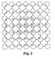
- Figure 5 is a perspective view of a section of a microlens sheeting depicting sample images formed in the radiation sensitive layer adjacent to individual microspheres, and further showing that the recorded images range from complete replication to partial replication of the composite image.
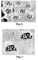
- Figures 6 and 7 are optical micrographs of a microlens sheeting imaged according to this invention, in which the radiation sensitive layer is an aluminum layer. As shown therein some of the images are complete, and others are partial.
- composite images can also be thought of as the result of the summing together of many images, both partial and complete, all with different perspectives of a real object.
- the many unique images are formed through an array of miniature lenses, all of which "see” the object or image from a different vantage point. Behind the individual miniature lenses, a perspective of the image is created in the material layer that depends on the shape of the image and the direction from which the imaging energy source was received. However, not everything that the lens sees is recorded in the radiation sensitive material. Only that portion of the image or object seen by the lens that has sufficient energy to modify the radiation sensitive material will be recorded.
- the "object" to be imaged is formed through the use of an intense light source by either tracing the outline of the "object” or by the use of a mask.
- the light from the object must radiate over a broad range of angles.
- all the light rays are carrying information about the object, but only from that single point, though the information is from the perspective of the angle of the light ray.
- the range of angles of the light rays emanating from an object is controlled by optical elements interposed between the object and the microlens material. These optical elements are chosen to give the optimum range of angles necessary to produce a composite image. The best selection of optical elements results in a cone of light whereby the vertex of the cone terminates at the position of the object. Optimum cone angles are greater than about 40 degrees.
- the object is demagnified by the miniature lenses and the light from the object is focused onto the energy sensitive coating against the backside of the miniature lens.
- the actual position of the focused spot or image at the backside of the lens depends upon the direction of the incident light rays originating from the object.
- Each cone of light emanating from a point on the object illuminates a fraction of the miniature lenses and only those miniature lenses illuminated with sufficient energy will record a permanent image of that point of the object.
- Geometrical optics will be used to describe the formation of various composite images according to the present invention. As noted previously, the imaging processes described below are preferred, but not exclusive, embodiments of the invention.
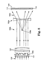
- incident energy 100 (light, in this example) is directed onto a light diffuser 101 to homogenize any non-uniformities in the light source.
- the diffusely scattered light 100a is captured and collimated by a light collimator 102 that directs the uniformly distributed light 100b towards a diverging lens 105a. From the diverging lens, the light rays 100c diverge toward the microlens sheeting 106.
- the energy of the light rays impinging upon the microlens sheeting 106 is focused by the individual microlenses 111 onto the material layer (a radiation sensitive coating 112, in the illustrated embodiment). This focused energy modifies the radiation sensitive coating 112 to provide an image, the size, shape, and appearance of which depends on the interaction between the light rays and the radiation sensitive coating.
- the arrangement shown in Figure 8 would provide a sheeting having a composite image that appears to an observer to float above the sheeting as described below, because diverging rays 100c, if extended backward through the lens, would intersect at the focal point 108a of the diverging lens. Stated differently, if a hypothetical "image ray" were traced from the material layer through each of the microspheres and back through the diverging lens, they would meet at 108a, which is where the composite image appears.
- a sheeting that has a composite image may be viewed using light that impinges on the sheeting from the same side as the observer (reflected light), or from the opposite side of the sheeting as the observer (transmitted light), or both.
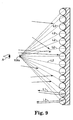
- Figure 9 is a schematic representation of a composite image that appears to the unaided eye of an observer A to float above the sheeting when viewed under reflected light.
- An unaided eye may be corrected to normal vision, but is not otherwise assisted by, for example, magnification or a special viewer.
- reflected light which may be collimated or diffuse
- light rays are reflected back from the imaged sheeting in a manner determined by the material layer struck by the light rays.
- the images formed in the material layer appear different than the non-imaged portions of the material layer, and thus an image can be perceived.
- light L2 may be reflected by the material layer back toward the observer.
- the material layer may not reflect light L1 back toward the observer well, or at all, from the imaged portions thereof.
- the observer may detect the absence of light rays at 108a, the summation of which creates a composite image that appears to float above the sheeting at 108a.
- light may be reflected from the entire sheeting except the imaged portions, which means that a relatively dark composite image will be apparent at 108a.
- the nonimaged material would absorb or transmit incident light, and that the imaged material would reflect or partially absorb incident light, respectively, to provide the contrast effect required to provide a composite image.
- the composite image under those circumstances would appear as a relatively bright composite image in comparison to the remainder of the sheeting, which would appear relatively dark.
- This composite image may be referred to as a "real image" because it is actual light, and not the absence of light, that creates the image at focal point 108a.
- Various combinations of these possibilities can be selected as desired.
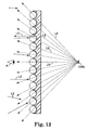
- Certain imaged sheetings can also be viewed by transmitted light, as shown in Figure 10 .
- transmitted light For example, when the imaged portions of the material layer are translucent and the nonimaged portions are not, then most light L3 will be absorbed or reflected by the material layer, while transmitted light L4 will be passed through the imaged portions of the material layer and directed by the microlenses toward the focal point 108a.
- the composite image will be apparent at the focal point, where it will in this example appear brighter than the remainder of the sheeting.
- This composite image may be referred to as a "real image" because it is actual light, and not the absence of light, that creates the image at focal point 108a.
- the imaged portions of the material layer are not translucent but the remainder of the material layer is, then the absence of transmitted light in the areas of the images will provide a composite image that appears darker than the remainder of the sheeting.
- a composite image may also be provided that appears to be suspended on the opposite side of the sheeting from the observer.
- This floating image that floats below the sheeting can be created by using a converging lens instead of the diverging lens 105 shown in Figure 8 .
- the incident energy 100 (light, in this example) is directed onto a diffuser 101 to homogenize any non-uniformities in the light source.
- the diffuse light 100a is then collected and collimated in a collimator 102 that directs the light 100b toward a converging lens 105b.
- the light rays 100d are incident on the microlens sheeting 106, which is placed between the converging lens and the focal point 108b of the converging lens.
- the energy of the light rays impinging upon the microlens sheeting 106 is focused by the individual microlenses 111 onto the material layer (a radiation sensitive coating 112, in the illustrated embodiment).
- This focused energy modifies the radiation sensitive coating 112 to provide an image, the size, shape, and appearance of which depends on the interaction between the light rays and the radiation sensitive coating.
- the arrangement shown in Figure 11 would provide a sheeting having a composite image that appears to an observer to float below the sheeting as described below, because converging rays 100d, if extended through the sheeting, would intersect at the focal point 108b of the diverging lens.
- Sheeting having a composite image that appears to float below the sheeting can also be viewed in reflected light, transmitted light, or both.
- Figure 12 is a schematic representation of a composite image that appears to float below the sheeting when viewed under reflected light.
- light L5 may be reflected by the material layer back toward the observer.
- the material layer may not reflect light L6 back toward the observer well, or at all, from the imaged portions thereof
- the observer may detect the absence of light rays at 108b, the summation of which creates a composite image that appears to float below the sheeting at 108b.
- light may be reflected from the entire sheeting except the imaged portions, which means that a relatively dark composite image will be apparent at 108b.
- the nonimaged material would absorb or transmit incident light, and that the imaged material would reflect or partially absorb incident light, respectively, to provide the contrast effect required to provide a composite image.
- the composite image under those circumstances would appear as a relatively bright composite image in comparison to the remainder of the sheeting, which would appear relatively dark.
- Various combinations of these possibilities can be selected as desired.
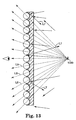
- imaged sheetings can also be viewed by transmitted light, as shown in Figure 13 .
- transmitted light For example, when the imaged portions of the material layer are translucent and the nonimaged portions are not, then most light L7 will be absorbed or reflected by the material layer, while transmitted light L8 will be passed through the imaged portions of the material layer.
- image rays back in the direction of the incident light results in the formation of a composite image at 108b.
- the composite image will be apparent at the focal point, where it will in this example appear brighter than the remainder of the sheeting.
- the imaged portions of the material layer are not translucent but the remainder of the material layer is, then the absence of transmitted light in the areas of the images will provide a composite image that appears darker than the remainder of the sheeting.
- Composite images made in accordance with the principles of the present invention may appear to be either two-dimensional, meaning that they have a length and width, and appear either below, or in the plane of, or above the sheeting, or three-dimensional, meaning that they have a length, width, and height. Three-dimensional composite images may appear below or above the sheeting only, or in any combination of below, in the plane of, and above the sheeting, as desired.
- the term "in the plane of the sheeting" refers only generally to the plane of the sheeting when the sheeting is laid flat. That is, sheeting that isn't flat can also have composite images that appear to be at least in part "in the plane of the sheeting" as that phrase is used herein.
- Three-dimensional composite images do not appear at a single focal point, but rather as a composite of images having a continuum of focal points, with the focal points ranging from one side of the sheeting to or through the sheeting to a point on the other side. This is preferably achieved by sequentially moving either the sheeting or the energy source relative to the other (rather than by providing multiple different lenses) so as to image the material layer at multiple focal points.
- the resulting spatially complex image essentially consists of many individual dots. This image can have a spatial extent in any of the three cartesian coordinates relative to the plane of the sheeting.
- a composite image can be made to move into a region of the microlensed sheeting where it disappears.
- This type of image is fabricated in a fashion similar to the levitation examples with the addition of placing an opaque mask in contact with the microlensed materials to partially block the imaging light for part of the microlensed material.
- the image can be made to move into the region where the imaging light was either reduced or eliminated by the contact mask. The image seems to "disappear" in that region.
- the composite images formed according to the present invention can have very wide viewing angles, meaning that an observer can see the composite image across a wide range of angles between the plane of the sheeting and the viewing axis.
- Composite images formed in microlens sheeting comprised of a monolayer of glass microspheres having an average diameter of approximately 70-80 micrometers and, when using an aspheric lens with a numerical aperture of 0.64, are visible within a conical field of view whose central axis is determined by the optical axis of the incident energy. Under ambient lighting, the composite image so formed is viewable across a cone of about 80-90 degrees full angle. Utilizing an imaging lens with less divergence or lower NA can form smaller half angle cones.
- Images formed by the process of this invention can also be constructed that have a restricted viewing angle. In other words, the image would only be seen if viewed from a particular direction, or minor angular variations of that direction.
- Such images are formed similar to the method described in Example One below, except that light incident on the final aspheric lens is adjusted so that only a portion of the lens is illuminated by the laser radiation.
- the partial filling of the lens with incident energy results in a restricted cone of divergent light incident upon the microlensed sheeting.
- the composite image appears only within a restricted viewing cone as a dark gray image on a light gray background. The image appears to be floating relative to the microlens sheeting.
- This example describes an embedded lens sheeting with an aluminum material layer, and a composite image that appeared to float above the sheeting.
- An optical train of the type depicted in Figure 14 was used to form the floating image.
- the optical train consisted of a Spectra Physics Quanta-RayTM DCR-2(10) Nd:YAG laser 300 operating in a Q-switched mode at its fundamental wavelength of 1.06 micrometers.
- the pulse width of this laser is typically from 10-30 ns.
- the energy was redirected by a 99% reflective turning mirror 302, a ground glass diffuser 304, a 5X beam expansion telescope 306, and an aspheric lens 308 with a numerical aperture of 0.64 and a focal length of 39.0 mm.
- the light from the aspheric lens 308 was directed toward an XYZ stage 310.
- the stage was composed of three linear stages, and is available from Aerotech Inc. of Pittsburgh, Pennsylvania under the designation ATS50060.
- One linear stage was used to move the aspheric lens along the axis between the aspheric focal point and the microlens sheeting (the z-axis), and the other two stages enabled the sheeting to be moved in two mutually orthogonal horizontal axes relative to the optical axis.
- the laser light was directed toward the ground glass diffuser 304 to eliminate any beam inhomogeneities caused by thermal lensing.
- a 5X beam expansion telescope 306 collimated the diverging light from the diffuser and enlarged the light beam to fill the aspherical lens 308.
- the aspheric lens was positioned above the XY plane of the XYZ stage so that the focal point of the lens was 1 cm above the microlens sheeting 312.
- the laser output was adjusted to obtain approximately 8 milliJoules per square centimeter (8 mJ/cm 2 ) over the illuminated area of the energy meter 1 cm from the focal point of the aspheric lens.
- a sample of embedded lens sheeting 312 with a 80 nm thick aluminum radiation sensitive layer was affixed to the XYZ stage 310 so that the aluminum coated side faced away from the aspherical lens 308.
- a controller available from Aerotech, Inc. of Pittsburgh, Pennsylvania under the designation U21 provided the necessary control signals for movement of the XYZ stage 312 and control voltages for pulsing of the laser 300.
- the stages were moved by importing a CAD file into the controller with the x-y-z coordinate information, movement commands, and laser firing commands necessary to produce the image.
- An arbitrary complex composite image was formed by coordinating the movement of the X, Y and Z stages with the pulsing of the laser to trace the image in space above the microlensed material.
- the stage speed was adjusted to 50.8 centimeters/minute for a laser pulse rate of 10Hz. This formed continuous composite lines in the aluminum layer adjacent the microlenses.
- the images were dark gray against a light gray background.
- the resulting image was a planar composite image that appeared to float approximately 1 cm above the sheeting.
- the composite image displayed reasonably large movement in relation to an observer's viewing perspective, so an observer could easily view different aspects of the composite image depending upon the viewing angle.
- an exposed lens sheeting construction with a transparent mirror radiation sensitive layer was used to form a composite image that appeared to float below the microlens sheeting.
- the optical train used in Example One was also used in this Example.
- the microlensed sheeting was positioned relative to the aspheric lens 308 so that the lens was nearly in contact with the microlens sheeting.
- the laser output was adjusted to achieve approximately 14 mJ/cm 2 directly beneath the aspheric lens.
- the exposed lens sheeting consisted of partially embedded microspheres as described in U.S. Patent Number 3,801,183 , with a zinc-sulfide (ZnS) dielectric mirror vapor deposited onto one side of the microspheres.
- the thickness of the ZnS layer was nominally 60 nm.
- Example One the laser was operated at 10 Hz while the sheeting was moved at 50.8 cm/min, resulting in the formation of continuous composite lines in the microlensed sheeting.
- a "globe" pattern (a circle with four inscribed arcs) was traced by the staging system.
- the globe appeared as a dark image against a white/yellow background.
- the dark composite image appeared to float approximately 39 mm below the sheeting.
- the location of the composite image corresponded to the location of the focal point of the aspheric lens, which for this Example correlated to approximately 39 mm behind the lens.
- This Example describes forming a composite image in an exposed lens sheeting with an aluminum radiation sensitive layer using a lens array in place of a single aspheric lens.
- An optical train of the type depicted in Figure 15 was used to form a floating composite image.
- the optical train consisted of a Q-switched laser 300, a 99% reflective mirror 302, an optical diffuser 304, and a beam expansion telescope 306. These components of the optical train used in this example are identical to those described in Example One.
- Also included in the optical train of this Example was a two-dimensional lens array 407, a reflective mask 409 and a negative bi-concave lens 411. Areas of the reflective mask 409 were transparent, to coincide with the areas of the microlensed material 412 to be exposed to the laser radiation, while the remaining surface of the mask was opaque or reflective.
- the lens array 407 consisted of a fused silica refractive microlens array available from MEMS Optical, LLC of Huntsville, Alabama under the designation 3038. This closed packed spherical lens array was placed almost in contact with a negative biconcave lens 411 having a diameter of 75 mm and focal length of negative 150 mm. Exposed lens sheeting 412 with an 80 nm thick aluminum radiation sensitive layer was placed within 25 mm of the negative bi-concave lens 411. The microlensed material was placed approximately 1 cm from the focal length of the combined optical path of the mircrolens array and the negative bi-concave lens. The output from the laser was adjusted to produce approximately 4 mJ/cm 2 at the surface of the exposed lens surface of the microlensed sheeting. A single laser pulse was activated to expose the entire image.
- the resulting imaged microlensed sheeting when viewed in ambient light, revealed images that appeared to float approximately 1 cm above the sheeting. The image appeared dark gray against a light gray background.
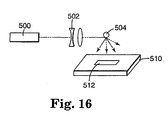
- the diverging light source was obtained by reflection from a scattering source.
- the scattering reflector consisted of a ceramic bead approximately 5 mm in diameter.
- An optical train of the type depicted in Figure 16 was used in this Example. It consisted of a Q-switched Nd:YAG laser 500, similar to that descried in Example One, followed by a telescope 502 which reduced the size of the incident laser beam to a diameter of approximately 1 mm.
- the light was then impinged upon the ceramic bead 504 at an angle sufficiently deviated from normal so as to illuminate approximately one quarter of the hemisphere of the ceramic bead 504 facing the microlens sheeting 512. This was confirmed by viewing the scattered radiation through an infrared camera.
- the ceramic bead 504 was positioned above the XY stage 510 at a distance of approximately 25 mm.
- the incident light from the laser was adjusted to be parallel to the sample stage.
- Embedded lens sheeting 512 with an 80 nm aluminum radiation sensitive layer was affixed to an XY stage 510 and a controller provided control signals to the stage and laser.
- the laser output was adjusted to obtain approximately 8 mJ/cm 2 at the surface of the microlens sheeting.
- Illumination of the ceramic bead 504 was adjusted to obtain the most uniform light exposure to the surface of the microlensed sheeting 512.
- the XY stage 510 was moved at 50.8 cm/minute with the laser pulsing at 10 Hz. A complex image was traced out with the stage while the microlensed sheeting was exposed to the scattered radiation from the ceramic reflector.
- the material layer of an embedded lens sheeting consisted of multilayer optical stacks, tuned for specific colors in the visible spectrum.
- thin film layers were deposited by vacuum evaporation and plasm polymerization to obtain a layer sequence consisting of chromium /plasma polymerized butadiene /silicon dioxide /aluminum, with the chromium layer being adjacent to the embedded lens.
- the thicknesses of the individual materials were adjusted to obtain colors in the red, green, and blue portions of the visible spectrum.
- Table 1 provides the specific thicknesses of the individual materials prepared.
- Table 1 Multilayer Construction Sample Cr (nm) PP (nm) SiO 2 (nm) Al (nm) Color 1 4 97 0 80 Blue 2 4 65 65 80 Light Blue 3 4 89 65 80 Green 4 4 165 20 80 Red/Blue
- the coated microlens base sheets were then laminated to a backing with the multilayers in contact with the laminating material.
- the liner of the microlens sheeting was then removed to expose the front surface of the embedded lenses with colors given by the above table.
- Example One An optical train as described in Example One was used to image the samples of this example.
- the focal point of the asphere was positioned 1 cm above the microlens sheeting.
- the laser output was adjusted to obtain an energy density of 5 mJ/cm 2 at the surface of the microlens sheeting.
- the optical properties of the multilayer stacks were modified in the regions irradiated.
- a globe pattern was traced to provide images in the multilayer stacks in a manner similar to that described in Example One.
- This example describes a second type of multilayer tuned stack as the radiation sensitive layer for producing a colored composite image.
- the optical stacks were prepared on a microlensed base sheet consisting of embedded lens sheeting.
- thin film layers were deposited by vacuum evaporation to obtain a layer sequence consisting of chromium/cryolite/aluminum (Cr/Na 3 AlF 6 /Al), chromium/silicon dioxide/aluminum (Cr/SiO 2 /Al), or chromium/magnesium fluoride/aluminum (Cr/MgF 2 /Al), as shown in Table 2, below.
- the thicknesses of the dielectric materials, SiO 2 , Na 3 AlF 6 and MgF 2 were adjusted to obtain a variety of colors in the visible spectrum. Table 2 provides the specific thicknesses of the individual materials prepared in the various samples. Table 2: Multilayer Construction Sample Cr Thickness (nm) Na 3 AlF 6 Thickness (nm) SiO 2 Thickness (nm) MgF 2 Thickness (nm) Al Thickness (nm) Color Imaging Energy Density (mJ/cm 2 ) A 4.8 200 0 0 83 Blue 12.7 B 4.2 0 135 0 83 Deep Blue 8.6 C 4.2 0 0 259 83 Aquagreen 8.6 D 4.2 0 275 0 83 Violet 7.5 E 4.2 0 160 0 83 Green 7.5 F 4.2 0 225 0 83 Orange-tan 7.5
- the coated microlens base sheets were then laminated to a backing such that the multilayer was in contact with the laminating material.
- the liner of the microlens sheeting was then removed to expose the front surface of the embedded lenses with colors given by the above table.
- Example One An optical train as described in Example One was used to image these samples.
- the position of the final aspheric lens was positioned to be almost in contact with the sample to provide a composite image that appeared to float below the sheeting.
- the laser energy was adjusted to obtain an energy density that would permanently alter the optical properties of the respective multilayer stacks, as shown in Table 2.
- the alphanumeric characters "SAMPLE" were traced for the image in this material in a manner similar to that described in Example One.
- the composite image appeared dark with a white/yellow outline against the background color of the microlensed sheeting. All composite images appeared to float approximately 39 mm below the sheeting and to move with respect to an observer viewing the sheeting.
- a color composite image was formed in an embedded lens sheeting using a phase change alloy of 50 atomic percent Silver and 50 atomic percent of Zinc (Ag 50 Zn 50 ) and a tuned bilayer stack consisting of chromium and silicon dioxide as the radiation sensitive layer.
- the phase change alloy was not ablated by the applied radiation, while the tuned bilayer enhances the spectral reflectance in the blue portion of the visible electromagnetic spectrum.
- the radiation sensitive layer was deposited onto the spacer layer of the enclosed lens sheeting in a manner similar to the procedure used to deposit the thin film layers of the multilayer stack unto the microlensed base sheet in Example Five.
- the chromium and silicon dioxide layers were vacuum deposited onto the polymeric spacer layer to thicknesses of 40 nm and 260 nm, respectively.
- an 80 nm thick layer of Ag 50 Zn 50 alloy was sputter deposited onto the silicon dioxide layer. The samples were then laminated and stripped to expose the clear portion of the microlens sheeting.
- the sheeting when viewed under ambient (reflected) light, appeared to be violet-blue.
- An optical train similar to Example One was used to image the Ag 50 Zn 50 radiation sensitive layer.
- a continuous wave Nd:YAG laser operating at a wavelength of 1.06 um, was used as the energy source.
- the pulse width was controlled by the use of an acousto-optic modulator in the optical train.
- the first order diffraction beam was sent through an optical train of the type depicted in Figure 14 . Samples of the enclosed lens sheeting were affixed to an XYZ stage.
- the laser power into the acousto-optic modulator was adjusted to give 810 mW of power at the microlensed material.
- the acousto-optic modulator was set to achieve 20 Hz pulsing at 100 microsecond pulse widths.
- a positive aspheric lens, as described in Example One, was placed 12mm above the surface of the microlensed material. An image was traced out with the XYZ stage while the laser radiation exposed the radiation sensitive layer.
- microlens sheeting a replicated lens structure with a copper radiation sensitive layer was used as the microlens sheeting.
- Replicated sheeting of the type described in U.S. Patent Number 5,254,390 was used as the microlens sheeting.
- a radiation sensitive layer of copper was vacuum evaporated on to the flat surface of the sheeting to a thickness of 80 nm.
- the microreplicated microlensed material was exposed to laser radiation from an optical train as described in Example One.
- the final aspheric lens was positioned with the focal point 6.5 mm away from the surface of the microlensed material.
- the laser output was adjusted to give approximately 7 mJ/cm 2 at the surface of the sheeting.
- the laser was set to pulse at 10Hz while the XYZ staging moved at a speed of 50.8 cm/minute.
- a "globe" pattern (a circle with four inscribed arcs) was traced above the sample.
- This Example describes the combination of a planar composite image with a composite image that appeared to float below the sheeting.
- Exposed lens microlens sheeting with an 80 nm thick aluminum radiation sensitive layer was imaged using the optical configuration described in Example One.
- the aspheric lens was positioned nearly in contact with the microlens sheeting, and the laser output was adjusted to yield 4 mJ/cm 2 at the sample surface.
- the controller was programmed to trace the alphanumeric characters "SAMPLE.”
- An absorptive mask was placed on top of the open sheeting. This mask was made by printing rows of the alphanumeric characters "3M" onto transparency sheets by way of a conventional photocopier. The alphanumeric characters absorbed the radiation while the surrounding areas would transmit the laser radiation.
- the exposed lens sheeting with this absorptive mask was positioned so that the "SAMPLE" characters were formed over the top of the mask position.
- This Example describes a sheeting with a complex, three-dimensional image.
- An embedded lens microlens sheeting with an 80 nm thick aluminum radiation sensitive layer was used in this Example.
- the optical train used in Example One was used.
- the microlensed sheeting was attached to the XY plane of an XYZ translation stage, while an aspheric lens was attached to the z-axis.
- the aspheric lens had a NA of 0.64 and a focal length of 39 mm.
- the controller was programmed to trace the outline of an isometric cube with 5 cm long cube diagonals (the distance between two opposite corners of the cube).
- the relative position and orientation of the cube as programmed in the controller placed one end of the composite cube image approximately 5 mm above the surface of the sheeting, and the other end of the composite cube image 5.5 cm above that surface.
- the cube image was oriented to place a corner of the cube closest to the observer.
- the energy per pulse from the laser was controlled to yield a constant energy density of 8 mJ/cm 2 at the sample surface regardless of the spacing between the diverging lens and the sheeting.
- the laser operated at 10 Hz and X, Y and Z stages moved at a speed of 50.8 cm/minute.
- the image of the isometric cube was continuously traced out in space above the microlensed sheeting by the controller.
- the isometric composite cube image When viewed in ambient lighting, the isometric composite cube image appeared dark gray against a light gray background, floating from between 5 mm and 5.5 cm above the surface. Furthermore, as an observer changed his or her viewing perspective, the isometric cube appeared to rotate in space above the microlens sheeting to expose sides of the cube that were previously obscured at different viewing angles.
- This Example describes a floating image that can be made to disappear. That is, the composite image can, by changing the viewing angle, be made to disappear from or reappear to view.
- An embedded lens sheeting with an 80 nm thick aluminum radiation sensitive layer was used.
- An optical train similar to that in Example One was used to form the images, and the distance of the aspheric lens from the sheeting was adjusted to position the focal point 1 cm above the microlensed sheeting.
- the controller was programmed to produce a "globe" pattern (a circle with four inscribed arcs) and the laser output was adjusted to provide 8 mJ/cm 2 at the sample surface.
- a square section of translucent tape was attached to the surface of the embedded lens sheeting. The square section of tape was positioned so that during the imaging of the globe, a portion of the area imaged by the laser would overlap the section covered by the translucent tape.
- Imaged sheeting containing the composite images of this invention are distinctive and impossible to duplicate with ordinary equipment.
- the composite images can be formed in sheeting that is specifically dedicated to applications such as passports, identification badges, identification graphics, and affinity cards. Documents requiring verification can have these images formed on the laminated sheeting for identification, authenticity, and enhancement.
- Conventional bonding means such as lamination, with or without adhesives, may be used.
- Providers of items of value such as boxed electronic products, compact discs, driver's licenses, title documents, passports or branded products, may simply apply the multilayer film of this invention to their products and instruct their customers only to accept as authentic items of value so labeled.
- composite images may be used as display materials for advertising, for license plates, and for numerous other applications in which the visual depiction of a unique image is desirable.
- Composite images may be formed on the same sheeting, and those composite images may be the same or different.
- Composite images may also be used along with other conventional images such as printed images, holograms, isograms, diffraction gratings, kinegrams, photographs, and the like.
Claims (25)
- Bogen (10, 20, 30), umfassend:mindestens eine Schicht aus mehreren Mikrolinsen (12, 22, 34), wobei die Schicht eine erste und zweite Seite aufweist;eine Schicht aus strahlungsempfindlichem Material (16, 26, 36), das neben der ersten Seite der Schicht aus Mikrolinsen angeordnet ist, die, wenn sie einem bestimmten Ausmaß an Strahlung ausgesetzt wird, ihre Erscheinung ändert, um einen Kontrast mit einem Material bereitzustellen, das der Strahlung nicht ausgesetzt wurde;mehrere unterschiedliche einzelne Bilder von einem Objekt, das in dem Material ausgebildet ist, wobei die Bilder durch Lenken eines divergierenden oder konvergierenden Energiestrahls von einer Strahlungsquelle in Richtung der mehreren Mikrolinsen gebildet werden, wobei der Energiestrahl einen Brennpunkt aufweist, wobei die Strahlung, die auf jede Mikrolinse auftritt, einen eindeutigen Einfallswinkel relativ zu der Strahlung aufweist, die auf jede andere Mikrolinse auftritt, derart, dass jede der Mikrolinsen die Strahlungsenergie derart auf eine eindeutige Position auf dem strahlungsempfindlichen Material überträgt, dass jedes Bild einer anderen der mehreren Mikrolinsen zugeordnet ist, wobei das Maß, zu dem das Objekt als ein Bild hinter einer Mikrolinse reproduziert ist, von der auf die Mikrolinse einfallenden Energiedichte abhängt, derart, dass mindestens eines der Bilder ein Teilbild des Objekts ist, und wobei die Bilder mit dem Material, das der Strahlung nicht ausgesetzt ist, in Kontrast stehen, wobei die verschiedenen einzelnen Bilder des Objekts derart sind, dass dem bloßen Auge eines Beobachters ein zusammengesetztes Bild, bereitgestellt durch Zusammentragen der verschiedenen einzelnen Bilder, so erscheint, als ob es an dem Brennpunkt über oder unter dem Bogen, oder beides, schwebt.
- Bogen nach Anspruch 1, wobei das zusammengesetzte Bild(a) unter Auflicht; oder(b) unter Durchlicht über dem Bogen zu schweben scheint.
- Bogen nach Anspruch 1, wobei das zusammengesetzte Bild(a) unter Auflicht; oder(b) unter Durchlicht unter dem Bogen zu schweben scheint.
- Bogen nach einem der vorhergehenden Ansprüche, wobei es sich bei dem Material um ein metallisches strahlungsempfindliches Material handelt.
- Bogen nach Anspruch 4, wobei das metallische strahlungsempfindliche Material aus Aluminium, Silber, Kupfer, Gold, Titan, Zink, Zinn, Chrom, Vanadium, Tantal und Legierungen dieser Metalle ausgewählt ist.
- Bogen nach einem der Ansprüche 1 bis 3, wobei es sich bei dem Material um ein nichtmetallisches strahlungsempfindliches Material handelt.
- Bogen nach Anspruch 6, wobei das nichtmetallische strahlungsempfindliche Material aus Zinksulfid, Zinkselenid, Siliziumdioxid, Indiumzinnoxid, Zinkoxid, Magnesiumfluorid und Silizium ausgewählt ist.
- Bogen nach einem der Ansprüche 1 bis 3, wobei es sich bei dem Material um eine strahlungsempfindliche metallische Oxidverbindung handelt.
- Bogen nach Anspruch 8, wobei das strahlungsempfindliche metallische Oxidverbindungsmaterial aus Oxidverbindungen, die aus Aluminium, Eisen, Kupfer, Zinn und Chrom ausgebildet sind, ausgewählt ist.
- Bogen nach Anspruch 1 bis 3, wobei es sich bei dem Material um ein thermochromisches strahlungsempfindliches Material handelt.
- Bogen nach Anspruch 10, wobei das thermochromische strahlungsempfindliche Material aus Kupfercarbonat, Kupfernitrat mit Thioharnstoff, Kupfercarbonat mit schwefelenthaltenden Verbindungen von Thiolen, Thioethern, Sulfoxiden und Sulfonen, hydratisierten Sulfaten, Nitriden von Bor, Aluminium und Wismut ausgewählt ist.
- Bogen nach einem der Ansprüche 1 bis 3, wobei es sich bei dem Material um ein mehrschichtiges strahlungsempfindliches Dünnfilmmaterial handelt.
- Bogen nach einem der vorhergehenden Ansprüche, ferner umfassend eine zwischen der Materialschicht und den Mikrolinsen angeordnete Abstandsschicht.
- Bogen nach einem der vorhergehenden Ansprüche, wobei es sich bei dem Bogen um einen Bogen mit freiliegenden Linsen oder einen Bogen mit eingebetteten Linsen handelt.
- Bogen nach einem der vorhergehenden Ansprüche, wobei der Bogen mehr als ein zusammengesetztes Bild bereitstellt.
- Bogen nach einem der vorhergehenden Ansprüche, wobei der Bogen ferner eine Klebeschicht zum Auftragen des Bogens auf ein Substrat umfasst.
- Bogen nach Anspruch 1, wobei es sich bei dem zusammengesetzten Bild um ein zweidimensionales Bild oder ein dreidimensionales Bild handelt.
- Verfahren zum Ausbilden eines zusammengesetzten Bilds auf einem Mikrolinsenbogen nach einem der Ansprüche 1 bis 17, umfassend die folgenden Schritte:a. Bereitstellen eines Bogens (10, 20, 30) mit mindestens einer Schicht aus mehreren Mikrolinsen (12, 22, 34), wobei die Schicht eine erste und zweite Seite aufweist, und einer Schicht aus strahlungsempfindlichem Material (16, 26, 36), das neben der ersten Seite der Schicht aus Mikrolinsen angeordnet ist, die, wenn sie einem bestimmten Ausmaß an Strahlung ausgesetzt wird, ihre Erscheinung ändert, um einen Kontrast mit einem Material bereitzustellen, das der Strahlung nicht ausgesetzt wurde;b. Bereitstellen einer Strahlungsquelle (300, 500); undc. Ausbilden mehrerer unterschiedlicher Bilder von einem Objekt in dem Material durch Lenken eines divergierenden oder konvergierenden Energiestrahls, wobei der Energiestrahl einen Brennpunkt aufweist, von der Strahlungsquelle in Richtung der mehreren Mikrolinsen, wobei die Strahlung, die auf jede Mikrolinse auftritt, einen eindeutigen Einfallswinkel relativ zu der Strahlung ausweist, die auf jede andere Mikrolinse auftritt, derart, dass jede der Mikrolinsen die Strahlung derart auf eine eindeutige Position auf dem strahlungsempfindlichen Material überträgt, dass jedes Bild einer anderen der mehreren Mikrolinsen zugeordnet ist, wobei das Maß, zu dem das Objekt als ein Bild hinter einer Mikrolinse reproduziert ist, von der auf die Mikrolinse einfallenden Energiedichte abhängt, derart, dass mindestens eines der Bilder ein Teilbild des Objekts ist, und wobei die Bilder mit dem Material, das der Strahlung nicht ausgesetzt ist, in Kontrast stehen, wobei die verschiedenen einzelnen Bilder des Objekts derart sind, dass dem bloßen Auge des Beobachters ein zusammengesetztes Bild, bereitgestellt durch Zusammentragen der verschiedenen einzelnen Bilder, so erscheint, als ob es an dem Brennpunkt über oder unter dem Bogen, oder beides, schwebt.
- Verfahren nach Anspruch 18, wobei jedes Bild durch mehrfaches strukturiertes Aussetzen der Strahlungsquelle gegenüber gebildet wird, wobei der Bogen sich während jedes Aussetzens an einer unterschiedlichen Position relativ zur Strahlungsquelle befindet.
- Verfahren nach Anspruch 18, wobei jedes Bild durch mindestens einfaches Aussetzen der Strahlungsquelle gegenüber durch eine Linsenanordnung gebildet wird.
- Verfahren nach Anspruch 18, wobei das Verfahren wiederholt wird, um mehr als ein zusammengesetztes Bild auf dem Bogen bereitzustellen.
- Verfahren nach Anspruch 18, wobei die Bilder durch mehrfaches Aussetzen der Strahlungsquelle gegenüber gebildet werden, wobei sich der Bogen während jedes Aussetzens in unterschiedlichen Abständen von der Strahlungsquelle befindet.
- Verfahren nach Anspruch 18, wobei die Strahlungsquelle eine Strahlung mit einer Wellenlänge von zwischen 200 nm und 11 µm bereitstellt.
- Verfahren nach Anspruch 18, wobei es sich bei dem zusammengesetzten Bild um ein zweidimensionales Bild oder ein dreidimensionales Bild handelt.
- Bogen nach Anspruch 1, wobei der Bogen auf Fahrzeugkennzeichen oder auf Wertdokumente aufgetragen ist.
Priority Applications (2)
| Application Number | Priority Date | Filing Date | Title |
|---|---|---|---|
| EP10172537A EP2278384A3 (de) | 2000-02-22 | 2000-06-20 | Folie mit zusammengesetztem, schwebendem Bild |
| EP10181565A EP2284596A3 (de) | 2000-02-22 | 2000-06-20 | Folie mit zusammengestztem, schwebendem Bild |
Applications Claiming Priority (3)
| Application Number | Priority Date | Filing Date | Title |
|---|---|---|---|
| US510428 | 2000-02-22 | ||
| US09/510,428 US6288842B1 (en) | 2000-02-22 | 2000-02-22 | Sheeting with composite image that floats |
| PCT/US2000/016954 WO2001063341A1 (en) | 2000-02-22 | 2000-06-20 | Sheeting with composite image that floats |
Related Child Applications (1)
| Application Number | Title | Priority Date | Filing Date |
|---|---|---|---|
| EP10153129.1 Division-Into | 2010-02-10 |
Publications (2)
| Publication Number | Publication Date |
|---|---|
| EP1259851A1 EP1259851A1 (de) | 2002-11-27 |
| EP1259851B1 true EP1259851B1 (de) | 2010-08-25 |
Family
ID=24030697
Family Applications (3)
| Application Number | Title | Priority Date | Filing Date |
|---|---|---|---|
| EP00941580A Expired - Lifetime EP1259851B1 (de) | 2000-02-22 | 2000-06-20 | Mikrolinsen-folie mit zusammengesetztem, schwebendem bild |
| EP10181565A Withdrawn EP2284596A3 (de) | 2000-02-22 | 2000-06-20 | Folie mit zusammengestztem, schwebendem Bild |
| EP10172537A Withdrawn EP2278384A3 (de) | 2000-02-22 | 2000-06-20 | Folie mit zusammengesetztem, schwebendem Bild |
Family Applications After (2)
| Application Number | Title | Priority Date | Filing Date |
|---|---|---|---|
| EP10181565A Withdrawn EP2284596A3 (de) | 2000-02-22 | 2000-06-20 | Folie mit zusammengestztem, schwebendem Bild |
| EP10172537A Withdrawn EP2278384A3 (de) | 2000-02-22 | 2000-06-20 | Folie mit zusammengesetztem, schwebendem Bild |
Country Status (22)
| Country | Link |
|---|---|
| US (1) | US6288842B1 (de) |
| EP (3) | EP1259851B1 (de) |
| JP (2) | JP4885395B2 (de) |
| KR (1) | KR100749587B1 (de) |
| CN (1) | CN100392470C (de) |
| AR (1) | AR031555A1 (de) |
| AT (1) | ATE479125T1 (de) |
| AU (2) | AU5627100A (de) |
| BR (2) | BRPI0017132B1 (de) |
| CA (1) | CA2400894C (de) |
| DE (1) | DE60044883D1 (de) |
| HU (1) | HUP0301412A2 (de) |
| IL (1) | IL151304A0 (de) |
| MX (1) | MXPA02008143A (de) |
| MY (1) | MY124506A (de) |
| NZ (1) | NZ520890A (de) |
| PL (1) | PL356536A1 (de) |
| RU (1) | RU2273038C2 (de) |
| SK (1) | SK287986B6 (de) |
| TW (1) | TW522257B (de) |
| WO (1) | WO2001063341A1 (de) |
| ZA (1) | ZA200206714B (de) |
Cited By (2)
| Publication number | Priority date | Publication date | Assignee | Title |
|---|---|---|---|---|
| US9415539B2 (en) | 2011-05-31 | 2016-08-16 | 3M Innovative Properties Company | Method for making microstructured tools having discontinuous topographies, and articles produced therefrom |
| US9523919B2 (en) | 2011-05-31 | 2016-12-20 | 3M Innovative Properties Company | Methods for making differentially pattern cured microstructured articles |
Families Citing this family (158)
| Publication number | Priority date | Publication date | Assignee | Title |
|---|---|---|---|---|
| US6969635B2 (en) * | 2000-12-07 | 2005-11-29 | Reflectivity, Inc. | Methods for depositing, releasing and packaging micro-electromechanical devices on wafer substrates |
| US6534221B2 (en) | 1998-03-28 | 2003-03-18 | Gray Scale Technologies, Inc. | Method for fabricating continuous space variant attenuating lithography mask for fabrication of devices with three-dimensional structures and microelectronics |
| US7167615B1 (en) | 1999-11-05 | 2007-01-23 | Board Of Regents, The University Of Texas System | Resonant waveguide-grating filters and sensors and methods for making and using same |
| US7068434B2 (en) * | 2000-02-22 | 2006-06-27 | 3M Innovative Properties Company | Sheeting with composite image that floats |
| US7336422B2 (en) * | 2000-02-22 | 2008-02-26 | 3M Innovative Properties Company | Sheeting with composite image that floats |
| AU2001245787A1 (en) | 2000-03-17 | 2001-10-03 | Zograph, Llc | High acuity lens system |
| US20050231800A1 (en) * | 2001-12-21 | 2005-10-20 | Barret Lippey | Selective reflecting |
| US7515336B2 (en) * | 2001-12-21 | 2009-04-07 | Bose Corporation | Selective reflecting |
| US7520624B2 (en) * | 2001-12-21 | 2009-04-21 | Bose Corporation | Light enhancing |
| US6847483B2 (en) * | 2001-12-21 | 2005-01-25 | Bose Corporation | Selective reflecting |
| US7255909B2 (en) * | 2002-02-19 | 2007-08-14 | 3M Innovative Properties Company | Security laminate |
| KR101140087B1 (ko) * | 2002-06-13 | 2012-04-30 | 쓰리엠 이노베이티브 프로퍼티즈 캄파니 | 제어되는 인증서 생산 및 관리 시스템 |
| US20030232210A1 (en) * | 2002-06-18 | 2003-12-18 | 3M Innovative Properties Company | Ink-receptive foam article |
| JP4238356B2 (ja) * | 2002-10-03 | 2009-03-18 | 独立行政法人産業技術総合研究所 | 認証システム、光放射装置、認証装置および認証方法 |
| DE20220078U1 (de) * | 2002-12-30 | 2003-03-27 | Shueh Ho Yuan | Vorrichtung zum Entnehmen von Lichtern |
| US7046447B2 (en) * | 2003-01-13 | 2006-05-16 | Pc Mirage, Llc | Variable focus system |
| US7655296B2 (en) | 2003-04-10 | 2010-02-02 | 3M Innovative Properties Company | Ink-receptive foam article |
| US7820282B2 (en) * | 2003-04-10 | 2010-10-26 | 3M Innovative Properties Company | Foam security substrate |
| WO2004104694A1 (ja) * | 2003-05-26 | 2004-12-02 | Sharp Kabushiki Kaisha | 反射型スクリーン |
| US20050031820A1 (en) * | 2003-08-04 | 2005-02-10 | Gorman Gregory Winfield | Information-bearing pavement tape |
| US8486208B2 (en) * | 2003-08-04 | 2013-07-16 | Parkmarx Advertising, Llc | Cold crack additive on paving advertising and related methods |
| ES2291932T3 (es) * | 2003-08-29 | 2008-03-01 | Bae Systems Plc | Dispositivo retrorreflectante que comprende lentes con indice en gradiente. |
| US8867134B2 (en) | 2003-11-21 | 2014-10-21 | Visual Physics, Llc | Optical system demonstrating improved resistance to optically degrading external effects |
| EP1695121B1 (de) * | 2003-11-21 | 2014-06-04 | Visual Physics, LLC | Mikrooptisches sicherheits- und bildpräsentationssystem |
| WO2005083661A1 (ja) * | 2004-02-27 | 2005-09-09 | Nippon Carbide Kogyo Kabushiki Kaisha | 盗難防止構造を具備した表示装置 |
| WO2005100041A2 (en) * | 2004-04-13 | 2005-10-27 | Digimarc Corporation | Retroreflective security features in secure documents |
| WO2005106601A2 (en) * | 2004-04-30 | 2005-11-10 | De La Rue International Limited | Arrays of microlenses and arrays of microimages on transparent security substrates |
| US7658980B2 (en) * | 2004-08-06 | 2010-02-09 | 3M Innovative Properties Company | Tamper-indicating printable sheet for securing documents of value and methods of making the same |
| US7648744B2 (en) * | 2004-08-06 | 2010-01-19 | 3M Innovative Properties Company | Tamper-indicating printable sheet for securing documents of value and methods of making the same |
| WO2006041812A2 (en) * | 2004-10-05 | 2006-04-20 | Threeflow, Inc. | Method of producing improved lenticular images |
| US7616332B2 (en) * | 2004-12-02 | 2009-11-10 | 3M Innovative Properties Company | System for reading and authenticating a composite image in a sheeting |
| DE102005028162A1 (de) | 2005-02-18 | 2006-12-28 | Giesecke & Devrient Gmbh | Sicherheitselement und Verfahren zu seiner Herstellung |
| NL1028776C2 (nl) * | 2005-04-14 | 2006-10-20 | Sdu Identification Bv | Identificatie en werkwijze voor het vervaardigen daarvan. |
| US7517091B2 (en) * | 2005-05-12 | 2009-04-14 | Bose Corporation | Color gamut improvement in presence of ambient light |
| EP1893074B2 (de) * | 2005-05-18 | 2017-06-14 | Visual Physics, LLC | Bilddarstellung und mikrooptisches sicherheitssystem |
| JP2008540283A (ja) * | 2005-05-20 | 2008-11-20 | スリーエム イノベイティブ プロパティズ カンパニー | 多次元画像を有するディスペンサー |
| BRPI0613147B1 (pt) * | 2005-06-16 | 2017-11-28 | Avery Dennison Corporation | BACKGROUND OF THE INVENTION The present invention relates to a retro-reflective blade structure, a final incorporating product, a method for manufacturing it, a laminate for manufacturing a plurality of the retro-reflective blade structures, a method of manufacturing a transparent layer for the retro-reflective laminate and a method of manufacturing the tool plate THERMOPLASTIC BLADE FOR MANUFACTURING A TRANSPARENT LAYER FOR RETROREFLETIVE LAMINATION |
| MX2008001674A (es) | 2005-08-09 | 2008-04-07 | Hexion Specialty Chemicals Inc | Metodos y composiciones para la determinacion de la geometria de fractura en formaciones subterraneas. |
| US7733567B2 (en) * | 2005-08-11 | 2010-06-08 | Aptina Imaging Corporation | Method and apparatus for reducing microlens surface reflection |
| US7981499B2 (en) | 2005-10-11 | 2011-07-19 | 3M Innovative Properties Company | Methods of forming sheeting with a composite image that floats and sheeting with a composite image that floats |
| US20070158230A1 (en) * | 2006-01-06 | 2007-07-12 | The Procter & Gamble Company | Merchandising systems, methods of merchandising, and point-of-sale devices comprising micro-optics technology |
| WO2007109725A2 (en) * | 2006-03-21 | 2007-09-27 | Three Point Optics, Inc. | Active mask variable data integral imaging system and method |
| EP1845496A1 (de) * | 2006-04-12 | 2007-10-17 | Trüb AG | Sicherheitselement für einen Datenträger, Datenträger mit einem solchen Sicherheitselement, Halbfabrikat zur Herstellung eines Datenträgers sowie Verfahren zur Herstellung eines Datenträger |
| EP2018589A2 (de) * | 2006-05-12 | 2009-01-28 | Crane & Co., Inc. | Mikrooptische folienstruktur zur mit oder ohne sicherheitsdokument oder -etikett erfolgenden projektion von mit statischen bildern oder anderen projizierten bildern räumlich koordinierten bildern |
| US7609452B2 (en) * | 2006-06-12 | 2009-10-27 | Guardian Industries Corp. | 3D gauge face for vehicle dashboard |
| MX2009000185A (es) * | 2006-06-28 | 2009-07-03 | Visual Physics Llc | Sistema de presentacion de imagen y seguridad micro-optica. |
| US8096584B2 (en) | 2006-07-24 | 2012-01-17 | 3M Innovative Properties Company | Document authentication using template matching with fast masked normalized cross-correlation |
| US7951319B2 (en) * | 2006-07-28 | 2011-05-31 | 3M Innovative Properties Company | Methods for changing the shape of a surface of a shape memory polymer article |
| US7586685B2 (en) * | 2006-07-28 | 2009-09-08 | Dunn Douglas S | Microlens sheeting with floating image using a shape memory material |
| US20080027199A1 (en) | 2006-07-28 | 2008-01-31 | 3M Innovative Properties Company | Shape memory polymer articles with a microstructured surface |
| EP2055534B1 (de) | 2006-08-23 | 2013-04-17 | Nippon Carbide Kogyo Kabushiki Kaisha | Kennzeichentafel und rückstrahlende folie dafür |
| US20080080056A1 (en) * | 2006-08-29 | 2008-04-03 | Micron Technology, Inc. | Method and apparatus for reducing microlens surface reflection |
| US20100028619A1 (en) * | 2006-09-11 | 2010-02-04 | 3M Innovative Properties Company | Card with a tearable security laminate |
| US7800825B2 (en) | 2006-12-04 | 2010-09-21 | 3M Innovative Properties Company | User interface including composite images that float |
| US8120854B2 (en) * | 2006-12-28 | 2012-02-21 | 3M Innovative Properties Company | Interference films having acrylamide layer and method of making same |
| CN101573471A (zh) * | 2006-12-29 | 2009-11-04 | 3M创新有限公司 | 固化含有金属烷氧化物的膜的方法 |
| KR20150015013A (ko) * | 2006-12-29 | 2015-02-09 | 쓰리엠 이노베이티브 프로퍼티즈 컴파니 | 무기 또는 무기/유기 하이브리드 필름의 제조 방법 |
| US20080163610A1 (en) * | 2007-01-05 | 2008-07-10 | Matthew Thomas Baird | Method and system for regenerating exhaust system filtering and catalyst components using variable high engine idle |
| US8081368B2 (en) * | 2007-03-29 | 2011-12-20 | Bose Corporation | Selective absorbing |
| DE102007029204A1 (de) * | 2007-06-25 | 2009-01-08 | Giesecke & Devrient Gmbh | Sicherheitselement |
| DE102007029203A1 (de) * | 2007-06-25 | 2009-01-08 | Giesecke & Devrient Gmbh | Sicherheitselement |
| US7710645B2 (en) * | 2007-06-29 | 2010-05-04 | Bose Corporation | Selective reflecting for laser projector |
| CN102830494B (zh) * | 2007-07-11 | 2015-04-01 | 3M创新有限公司 | 具有浮动合成图像的片材 |
| JP2009020813A (ja) * | 2007-07-13 | 2009-01-29 | Three M Innovative Properties Co | タグおよびそれを用いた物品認識システム |
| JP2010537843A (ja) * | 2007-09-06 | 2010-12-09 | スリーエム イノベイティブ プロパティズ カンパニー | 微細構造物品を作製するための工具 |
| US9102083B2 (en) | 2007-09-06 | 2015-08-11 | 3M Innovative Properties Company | Methods of forming molds and methods of forming articles using said molds |
| CN101796443A (zh) | 2007-09-06 | 2010-08-04 | 3M创新有限公司 | 具有提供输出光区域控制的光提取结构的光导装置 |
| CN101821659B (zh) | 2007-10-11 | 2014-09-24 | 3M创新有限公司 | 色差共聚焦传感器 |
| CN101878438B (zh) * | 2007-11-27 | 2013-09-25 | 3M创新有限公司 | 形成具有悬浮合成图像的片材以及母模具的方法 |
| US8540158B2 (en) * | 2007-12-12 | 2013-09-24 | Yiwu Lei | Document verification using dynamic document identification framework |
| CN101946305B (zh) | 2007-12-12 | 2014-02-12 | 3M创新有限公司 | 用于制备具有改善的边缘清晰度的结构的方法 |
| US8194933B2 (en) * | 2007-12-12 | 2012-06-05 | 3M Innovative Properties Company | Identification and verification of an unknown document according to an eigen image process |
| JP2011508265A (ja) | 2007-12-21 | 2011-03-10 | スリーエム イノベイティブ プロパティズ カンパニー | 球形コア及び2つの同心光学干渉層を含む、再帰反射性物品及び再帰反射素子 |
| DE102007062089A1 (de) * | 2007-12-21 | 2009-07-02 | Giesecke & Devrient Gmbh | Verfahren zum Erzeugen einer Mikrostruktur |
| JP2011509421A (ja) * | 2007-12-21 | 2011-03-24 | スリーエム イノベイティブ プロパティズ カンパニー | 衣類、繊維及びフィラメント形態の再帰反射物品 |
| JP2011509422A (ja) * | 2007-12-21 | 2011-03-24 | スリーエム イノベイティブ プロパティズ カンパニー | 再帰反射安全物品 |
| CN101945965A (zh) * | 2007-12-28 | 2011-01-12 | 3M创新有限公司 | 柔性封装膜系统 |
| US20090173654A1 (en) * | 2008-01-04 | 2009-07-09 | Nanoventions Holdings, Llc | Merchandising Systems, Methods of Merchandising, and Point-Of-Sale Devices Comprising Micro-Optics Technology |
| US20090172978A1 (en) * | 2008-01-04 | 2009-07-09 | Nanoventions Holdings, Llc | Merchandising Systems, Methods of Merchandising, and Point-Of-Sale Devices Comprising Micro-Optics Technology |
| US20090173653A1 (en) * | 2008-01-04 | 2009-07-09 | Nanoventions Holdings, Llc | Merchandising Systems, Methods of Merchandising, and Point-Of-Sale Devices Comprising Micro-Optics Technology |
| US8615383B2 (en) | 2008-01-18 | 2013-12-24 | Lockheed Martin Corporation | Immersive collaborative environment using motion capture, head mounted display, and cave |
| US8217995B2 (en) | 2008-01-18 | 2012-07-10 | Lockheed Martin Corporation | Providing a collaborative immersive environment using a spherical camera and motion capture |
| EP2257854B1 (de) * | 2008-02-26 | 2018-10-31 | 3M Innovative Properties Company | Mehrphotonenbelichtungssystem |
| DE102008029638A1 (de) * | 2008-06-23 | 2009-12-24 | Giesecke & Devrient Gmbh | Sicherheitselement |
| EP2304069A4 (de) * | 2008-06-30 | 2012-01-04 | 3M Innovative Properties Co | Verfahren zur herstellung von anorganischen barrierefilmen oder anorganisch/organischen hybridbarrierefilmen |
| US8857028B2 (en) * | 2008-07-08 | 2014-10-14 | 3M Innovative Properties Company | Processes for producing optical elements showing virtual images |
| CN102150071A (zh) * | 2008-07-08 | 2011-08-10 | 3M创新有限公司 | 用于显示虚像的光学元件 |
| US8651720B2 (en) | 2008-07-10 | 2014-02-18 | 3M Innovative Properties Company | Retroreflective articles and devices having viscoelastic lightguide |
| WO2010006102A2 (en) | 2008-07-10 | 2010-01-14 | 3M Innovative Properties Company | Retroreflective articles and devices having viscoelastic lightguide |
| KR20160105527A (ko) | 2008-07-10 | 2016-09-06 | 쓰리엠 이노베이티브 프로퍼티즈 컴파니 | 점탄성 도광체 |
| EP2321677A4 (de) | 2008-08-08 | 2011-08-17 | 3M Innovative Properties Co | Lichtleiter mit viskoelastischer schicht zur handhabung von licht |
| DE102008046511A1 (de) | 2008-09-10 | 2010-03-11 | Giesecke & Devrient Gmbh | Darstellungsanordnung |
| US8111463B2 (en) | 2008-10-23 | 2012-02-07 | 3M Innovative Properties Company | Methods of forming sheeting with composite images that float and sheeting with composite images that float |
| CN201302625Y (zh) * | 2008-10-23 | 2009-09-02 | 上海复旦天臣研发中心有限公司 | 在薄片上刻录动感浮点图像的装置 |
| US7995278B2 (en) | 2008-10-23 | 2011-08-09 | 3M Innovative Properties Company | Methods of forming sheeting with composite images that float and sheeting with composite images that float |
| US8865293B2 (en) * | 2008-12-15 | 2014-10-21 | 3M Innovative Properties Company | Optically active materials and articles and systems in which they may be used |
| CN101750775B (zh) * | 2008-12-22 | 2012-05-30 | 北京京东方光电科技有限公司 | 二维与三维显示切换装置及其制造方法和液晶显示器 |
| CN202661719U (zh) * | 2009-03-10 | 2013-01-09 | 3M创新有限公司 | 具有浮现的合成图像的用户接口 |
| US20120091703A1 (en) * | 2009-04-06 | 2012-04-19 | Reserve Bank Of Australia | Security document with an optically variable image and method of manufacture |
| US20120099200A1 (en) | 2009-07-17 | 2012-04-26 | Nippon Carbide Industries Co., Inc. | Retroreflective sheeting of micro glass sphere provided with image having visual direction |
| US20110130508A1 (en) * | 2009-07-29 | 2011-06-02 | Alan David Pendley | Topside optical adhesive for micro-optical film embedded into paper during the papermaking process |
| KR101758940B1 (ko) | 2009-08-12 | 2017-07-17 | 비쥬얼 피직스 엘엘씨 | 탬퍼 표시 광 보안 장치 |
| EP2470931B1 (de) * | 2009-08-25 | 2016-03-09 | Avery Dennison Corporation | Retroreflektierender artikel |
| CN102092210B (zh) * | 2009-12-11 | 2015-06-03 | 奥普赛科安全集团股份有限公司 | 光学可变装置,安全装置和利用它的制品及其生产方法 |
| WO2011100277A1 (en) | 2010-02-10 | 2011-08-18 | 3M Innovative Properties Company | Illumination device having viscoelastic layer |
| JP6251569B2 (ja) | 2010-06-30 | 2018-01-10 | スリーエム イノベイティブ プロパティズ カンパニー | 空間的に選択的な複屈折性の減少を有する拡散反射光学フィルム |
| KR101877209B1 (ko) | 2010-06-30 | 2018-07-10 | 쓰리엠 이노베이티브 프로퍼티즈 컴파니 | 공간 선택적 복굴절 감소를 갖는 필름을 사용하는 마스크 처리 |
| KR101841310B1 (ko) | 2010-06-30 | 2018-03-22 | 쓰리엠 이노베이티브 프로퍼티즈 컴파니 | 공간 선택적 복굴절 감소를 갖는 지연기 필름 조합물 |
| JP5500548B2 (ja) * | 2010-07-01 | 2014-05-21 | 独立行政法人 国立印刷局 | 潜像画像形成体 |
| DE102010048262A1 (de) * | 2010-10-12 | 2012-04-12 | Giesecke & Devrient Gmbh | Darstellungselement |
| RU2535430C1 (ru) | 2010-11-15 | 2014-12-10 | Нэшнл Инститьют Оф Джапэн Сайнс Энд Текнолоджи Эйдженси | Устройство генерирования изображения с иллюзией, носитель, данные изображения, способ генерирования изображения с иллюзией, способ изготовления печатного носителя и программа |
| KR101032191B1 (ko) * | 2010-12-13 | 2011-05-02 | 이주현 | 입체용 다중 복합 렌즈 시트 |
| EP2667227A4 (de) | 2011-01-19 | 2017-05-10 | Nippon Carbide Industries Co., Inc. | Rückstrahlende folie mit mikroglaskugeln sowie in diesen installierten bildern mit sichtbaren ausrichtungen |
| RU2460108C1 (ru) * | 2011-01-21 | 2012-08-27 | Александр Борисович Зензинов | Способ получения параллакс-панорамограммы и вариоизображения |
| CN103477250B (zh) | 2011-01-28 | 2015-09-02 | 克瑞尼股份有限公司 | 一种激光标记的器件 |
| WO2012162057A2 (en) | 2011-05-20 | 2012-11-29 | 3M Innovative Properties Company | Laser-personalizable security articles |
| EP2710520B1 (de) | 2011-05-20 | 2016-04-27 | 3M Innovative Properties Company | Durch laser personalisierbare sicherheitsartikel |
| US10890692B2 (en) | 2011-08-19 | 2021-01-12 | Visual Physics, Llc | Optionally transferable optical system with a reduced thickness |
| US8665523B2 (en) * | 2011-09-12 | 2014-03-04 | 3M Innovative Properties Company | Multilayer 3D floating images in a single substrate |
| CA2857335A1 (en) | 2011-12-15 | 2013-06-20 | 3M Innovative Properties Company | A personalized security article and methods of authenticating a security article and verifying a bearer of a security article |
| RU2628481C2 (ru) * | 2012-05-14 | 2017-08-17 | Нэшнл Инститьют Оф Джапэн Сайнс Энд Текнолоджи Эйдженси | Устройство обработки изображения, способ обработки изображения, программа, печатный носитель и носитель записи |
| EA023384B1 (ru) * | 2012-05-18 | 2016-05-31 | Государственное Научное Учреждение "Физико-Технический Институт Национальной Академии Наук Беларуси" | Способ формирования защитного покрытия на полимерном основании |
| US8610976B1 (en) | 2012-06-27 | 2013-12-17 | 3M Innovative Properties Company | Image enhancement methods |
| US8743426B2 (en) | 2012-06-27 | 2014-06-03 | 3M Innovative Properties Company | Image enhancement methods |
| KR102014576B1 (ko) | 2012-08-17 | 2019-08-26 | 비쥬얼 피직스 엘엘씨 | 미세구조물을 최종 기판에 전사하기 위한 프로세스 |
| US9132690B2 (en) | 2012-09-05 | 2015-09-15 | Lumenco, Llc | Pixel mapping, arranging, and imaging for round and square-based micro lens arrays to achieve full volume 3D and multi-directional motion |
| CN102981193B (zh) * | 2012-11-15 | 2015-12-02 | 3M中国有限公司 | 用于模塑的薄膜、由其制备的模塑制品及其制备方法 |
| US10173453B2 (en) | 2013-03-15 | 2019-01-08 | Visual Physics, Llc | Optical security device |
| JP6032432B2 (ja) * | 2013-04-15 | 2016-11-30 | 独立行政法人 国立印刷局 | 画像形成体 |
| US9873281B2 (en) | 2013-06-13 | 2018-01-23 | Visual Physics, Llc | Single layer image projection film |
| US8922895B1 (en) | 2013-07-03 | 2014-12-30 | 3M Innovative Properties Company | Optical body with fresnel-rendering of complex topographical surface |
| TWI562891B (en) * | 2013-09-27 | 2016-12-21 | Rohm & Haas | Optical effect coating |
| BR112016021736A2 (pt) | 2014-03-27 | 2017-08-15 | Visual Physics Llc | Dispositivo ótico que produz efeitos óticos de tipo cintilante |
| US10766292B2 (en) | 2014-03-27 | 2020-09-08 | Crane & Co., Inc. | Optical device that provides flicker-like optical effects |
| ES2721757T3 (es) | 2014-07-17 | 2019-08-05 | Visual Physics Llc | Material de lámina polimérico mejorado para su uso en la obtención de documentos de seguridad poliméricos tales como billetes de banco |
| DE102014111171A1 (de) * | 2014-08-06 | 2016-02-11 | Bundesdruckerei Gmbh | Bilderfassungsvorrichtung zum Erfassen eines ersten Bildes eines Identifikationsdokumentes in einem ersten Wellenlängenbereich und eines zweiten Bildes des Identifikationsdokumentes in einem zweiten Wellenlängenbereich |
| CN104191825B (zh) | 2014-09-04 | 2016-05-11 | 苏州苏大维格光电科技股份有限公司 | 彩色动态图的激光打印装置及方法 |
| MX2017003423A (es) | 2014-09-16 | 2017-11-22 | Crane Security Tech Inc | Capa de lente de seguridad. |
| DE102015202106A1 (de) * | 2015-02-06 | 2016-08-11 | Tesa Scribos Gmbh | Optisch variables Sicherheitselement |
| CA2976218C (en) | 2015-02-11 | 2023-02-14 | Crane & Co., Inc. | Method for the surface application of a security device to a substrate |
| JP6582481B2 (ja) * | 2015-03-25 | 2019-10-02 | セイコーエプソン株式会社 | 虚像表示装置 |
| TWI576608B (zh) * | 2015-10-20 | 2017-04-01 | 梁伯嵩 | 光學隱形結構以及光學隱形裝置 |
| US10189294B2 (en) | 2015-12-03 | 2019-01-29 | Lumenco, Llc | Arrays of individually oriented micro mirrors for use in imaging security devices for currency and brand authentication |
| US10317691B2 (en) | 2015-12-03 | 2019-06-11 | Lumenco, Llc | Arrays of individually oriented micro mirrors providing infinite axis activation imaging for imaging security devices |
| FR3046112B1 (fr) * | 2015-12-23 | 2019-06-14 | Idemia France | Procede de realisation d'images selectivement visibles en variant l'angle d'observation par gravure au travers d'un reseau lenticulaire |
| RU2629150C1 (ru) * | 2016-03-15 | 2017-08-24 | Общество с ограниченной ответственностью "МеталлЭффект" | Устройство для формирования динамического изображения и способ его получения |
| JP6942733B2 (ja) | 2016-05-13 | 2021-09-29 | スリーエム イノベイティブ プロパティズ カンパニー | セキュリティ要素を使用した光学活性物品の偽造品検出 |
| CN106560733B (zh) * | 2016-06-01 | 2022-05-24 | 杭州飞像科技有限公司 | 一种空中成像元件、空中成像显示装置及其应用 |
| EP3485321A4 (de) | 2016-07-15 | 2020-04-01 | Sun Chemical Corporation | 3d/flip/bewegungsfotosubstrat, bildgebungsverfahren und anwendungen davon |
| US10663657B2 (en) | 2016-07-15 | 2020-05-26 | Light Field Lab, Inc. | Selective propagation of energy in light field and holographic waveguide arrays |
| CN110582412B (zh) | 2017-02-10 | 2022-08-30 | 克瑞尼股份有限公司 | 机器可读光学安全器件 |
| EP3737980A4 (de) | 2018-01-14 | 2021-11-10 | Light Field Lab, Inc. | Systeme und verfahren zur transversalen energielokalisierung in energierelais mit geordneten strukturen |
| TWI695992B (zh) * | 2018-04-03 | 2020-06-11 | 英屬開曼群島商康而富控股股份有限公司 | 利用不同折射率的材料所組成的鏡片結構 |
| TWI695991B (zh) * | 2018-04-03 | 2020-06-11 | 英屬開曼群島商康而富控股股份有限公司 | 利用不同折射率的材料所組成的鏡片結構 |
| TWI670515B (zh) * | 2018-04-03 | 2019-09-01 | 英屬開曼群島商康而富控股股份有限公司 | 利用不同折射率的材料所組成的鏡片結構(一) |
| KR102249359B1 (ko) * | 2019-06-19 | 2021-05-06 | 윤세원 | 재귀반사시트 |
| EP3835851A1 (de) | 2019-12-10 | 2021-06-16 | Thales Dis France Sa | Lasergravierbares schwebendes bild für sicherheitslaminate |
| CN214633896U (zh) * | 2020-06-16 | 2021-11-09 | 厦门市维尔昇科技有限公司 | 一种微纳米结构卡牌 |
Citations (2)
| Publication number | Priority date | Publication date | Assignee | Title |
|---|---|---|---|---|
| US3801183A (en) * | 1973-06-01 | 1974-04-02 | Minnesota Mining & Mfg | Retro-reflective film |
| US5712731A (en) * | 1993-05-11 | 1998-01-27 | Thomas De La Rue Limited | Security device for security documents such as bank notes and credit cards |
Family Cites Families (81)
| Publication number | Priority date | Publication date | Assignee | Title |
|---|---|---|---|---|
| US1918705A (en) | 1930-12-20 | 1933-07-18 | Herbert E Ives | Parallax panoramagram |
| US1905716A (en) | 1931-04-03 | 1933-04-25 | Bell Telephone Labor Inc | Making stereoscopic parallax panoramagrams from pseudoscopic parallax panoramagrams |
| US2039648A (en) | 1933-05-06 | 1936-05-05 | Perser Corp | Camera for making parallax panoramagrams |
| US2063985A (en) | 1935-05-24 | 1936-12-15 | Winnek Stereoscopic Processes | Apparatus for making a composite stereograph |
| US2279825A (en) | 1940-07-24 | 1942-04-14 | Nicholas T Kaszab | Stereoscopic picture with aplanat focusing element |
| US2326634A (en) | 1941-12-26 | 1943-08-10 | Minnesota Mining & Mfg | Reflex light reflector |
| US2500511A (en) | 1944-07-10 | 1950-03-14 | Reliephographie Soc Pour L Exp | Relief photograph having reflecting back |
| US2622472A (en) | 1946-05-25 | 1952-12-23 | Reliephographie Soc Pour L Exp | Apparatus for relief and movement photography |
| US2833176A (en) | 1953-07-21 | 1958-05-06 | Ossoinak Andres Juan Luis | Arrangement for the exhibition of dynamic scenes to an observer in movement with respect to a screen |
| US3357770A (en) | 1961-10-02 | 1967-12-12 | Intermountain Res And Engineer | Stereoscopic viewing apparatus which includes a curved lenticular screen in front ofa curved picture supporting surface |
| US3161509A (en) | 1962-04-24 | 1964-12-15 | Eastman Kodak Co | Line stereo color pictures |
| FR1342335A (fr) | 1962-09-29 | 1963-11-08 | Centre Nat Rech Scient | Perfectionnements aux dispositifs pour l'obtention d'images virtuelles de divers objets |
| US3154872A (en) | 1963-02-13 | 1964-11-03 | Minnesota Mining & Mfg | Tamper-proof markings for reflecting structures |
| US3306974A (en) | 1963-03-08 | 1967-02-28 | Gilbert R Johnson | Color reproduction with a monochromatic gradient line image |
| US3365350A (en) | 1965-04-28 | 1968-01-23 | Cahn Leo | Three dimensional picture |
| US5449597A (en) | 1966-04-21 | 1995-09-12 | Sawyer; George M. | Lippmann process of color photography, which produces a photograph with a 2-dimensional image, to result in another process of color photography which produces a photograph with a 3-dimensional image |
| US3459111A (en) | 1966-06-20 | 1969-08-05 | Polaroid Corp | Image dissection camera |
| US3503315A (en) | 1966-12-12 | 1970-03-31 | Lucas Industries Ltd | Integral photography |
| US3607273A (en) | 1967-03-08 | 1971-09-21 | American Screen Process Equip | Image formation by selective foam generation |
| US3584369A (en) | 1967-10-11 | 1971-06-15 | Roger Lannes De Montebello | Process of making reinforced lenticular sheet |
| AT307280B (de) * | 1969-05-09 | 1973-05-10 | Swarovski & Co | Reflexfolie und Verfahren zu ihrer Herstellung |
| US3613539A (en) | 1968-07-26 | 1971-10-19 | Leslie Peter Dudley | Integral photography |
| US3551025A (en) * | 1969-03-28 | 1970-12-29 | Minnesota Mining & Mfg | Highly flexible reflex reflecting constructions |
| US3676130A (en) | 1969-11-26 | 1972-07-11 | Bell Telephone Labor Inc | Beaded plate integral photography |
| US3706486A (en) | 1970-08-27 | 1972-12-19 | Roger De Montebello | Reinforced lenticular sheet with plural apertured sheets |
| US3751258A (en) | 1970-10-29 | 1973-08-07 | Eastman Kodak Co | Autostereographic print element |
| US4121011A (en) | 1975-11-28 | 1978-10-17 | Raychem Corporation | Polymeric article coated with a thermochromic paint |
| US4541727A (en) * | 1975-12-16 | 1985-09-17 | Rosenthal Bruce A | Lenticular optical system |
| US4034555A (en) * | 1975-12-16 | 1977-07-12 | Rosenthal Bruce A | Lenticular optical system |
| US4099838A (en) | 1976-06-07 | 1978-07-11 | Minnesota Mining And Manufacturing Company | Reflective sheet material |
| US4082426A (en) | 1976-11-26 | 1978-04-04 | Minnesota Mining And Manufacturing Company | Retroreflective sheeting with retroreflective markings |
| US4200875A (en) | 1978-07-31 | 1980-04-29 | The United States Of America As Represented By The Secretary Of The Air Force | Apparatus for, and method of, recording and viewing laser-made images on high gain retroreflective sheeting |
| US4315665A (en) | 1979-09-07 | 1982-02-16 | Eidetic Images, Inc. | Composite optical element having controllable light transmission and reflection characteristics |
| US4424990A (en) | 1980-01-30 | 1984-01-10 | Raychem Corporation | Thermochromic compositions |
| US4509837A (en) | 1980-08-29 | 1985-04-09 | Michiel Kassies | Real image projection device |
| JPH0617981B2 (ja) | 1982-04-07 | 1994-03-09 | ストリ−ト,グレイアム スチユワ−ト ブランドン | 自動的立体像を製造するに使用する方法及び装置 |
| US4557590A (en) | 1982-09-10 | 1985-12-10 | Winnek Douglas Fredwill | Method and apparatus for making true three-dimensional photographs from pseudo three-dimensional photographs |
| US4634220A (en) | 1983-02-07 | 1987-01-06 | Minnesota Mining And Manufacturing Company | Directionally imaged sheeting |
| GB8326387D0 (en) | 1983-10-03 | 1983-11-02 | Brightad Ltd | Production of autostereoscopic images |
| US4618552A (en) | 1984-02-17 | 1986-10-21 | Canon Kabushiki Kaisha | Light receiving member for electrophotography having roughened intermediate layer |
| US4650283A (en) | 1984-08-03 | 1987-03-17 | Minnesota Mining And Manufacturing Company | Directionally imaged retroreflective sheeting |
| US4927238A (en) | 1984-11-27 | 1990-05-22 | Nicholas C. Terzis | Method and apparatus for displaying a three dimensional visual image |
| JPS61133349A (ja) | 1984-12-03 | 1986-06-20 | Hitachi Ltd | 分光反射率可変合金及び記録材料 |
| US4732453A (en) | 1984-12-10 | 1988-03-22 | Integrated Images, Inc. | Integral photography apparatus and method of forming same |
| US4629667A (en) | 1985-03-29 | 1986-12-16 | Minnesota Mining And Manufacturing Company | White reflective coating |
| US4691993A (en) | 1985-05-13 | 1987-09-08 | Minnesota Mining And Manufacturing Company | Transparent sheets containing directional images and method for forming the same |
| US4708920A (en) | 1985-09-16 | 1987-11-24 | Minnesota Mining And Manufacturing Company | Microlens sheet containing directional half-tone images and method for making the same |
| CA1267173A (en) | 1985-09-23 | 1990-03-27 | Thomas I. Bradshaw | Sheet containing contour-dependent directional image and method for forming the same |
| US4664966A (en) * | 1985-11-18 | 1987-05-12 | Minnesota Mining And Manufacturing Company | Enclosed-lens retroreflective sheeting having tough, weather-resistant, transparent cover film |
| US5064272A (en) | 1985-11-18 | 1991-11-12 | Minnesota Mining And Manufacturing Company | Encapsulated-lens retroreflective sheeting and method of making |
| US4935335A (en) | 1986-01-06 | 1990-06-19 | Dennison Manufacturing Company | Multiple imaging |
| US4775219A (en) | 1986-11-21 | 1988-10-04 | Minnesota Mining & Manufacturing Company | Cube-corner retroreflective articles having tailored divergence profiles |
| US4799739A (en) | 1987-08-10 | 1989-01-24 | Advanced Dimensional Displays, Inc. | Real time autostereoscopic displays using holographic diffusers |
| JPH0432708Y2 (de) * | 1988-06-10 | 1992-08-06 | ||
| US5644431A (en) | 1990-05-18 | 1997-07-01 | University Of Arkansas, N.A. | Directional image transmission sheet and method of making same |
| US5254390B1 (en) | 1990-11-15 | 1999-05-18 | Minnesota Mining & Mfg | Plano-convex base sheet for retroreflective articles |
| US5169707A (en) | 1991-05-08 | 1992-12-08 | Minnesota Mining And Manufacturing Company | Retroreflective security laminates with dual level verification |
| AU652051B2 (en) | 1991-06-27 | 1994-08-11 | Eastman Kodak Company | Electronically interpolated integral photography system |
| JP2746790B2 (ja) | 1992-03-02 | 1998-05-06 | 富士写真フイルム株式会社 | 立体画像記録方法および立体画像記録装置 |
| US5279912A (en) | 1992-05-11 | 1994-01-18 | Polaroid Corporation | Three-dimensional image, and methods for the production thereof |
| US5359454A (en) | 1992-08-18 | 1994-10-25 | Applied Physics Research, L.P. | Apparatus for providing autostereoscopic and dynamic images |
| EP0583766A1 (de) | 1992-08-18 | 1994-02-23 | Eastman Kodak Company | Auf Linsenrastermaterial gedruckte Tiefenbilder |
| US5330799A (en) | 1992-09-15 | 1994-07-19 | The Phscologram Venture, Inc. | Press polymerization of lenticular images |
| US5717844A (en) | 1993-01-06 | 1998-02-10 | Lo; Allen Kwok Wah | Method and apparatus for producing 3D pictures with extended angular coverage |
| JPH06308895A (ja) * | 1993-04-23 | 1994-11-04 | Copal Co Ltd | 表示装置 |
| FR2704951B1 (fr) | 1993-05-05 | 1995-07-21 | Particulier Editions | Dispositif de formation d'image autostereoscopique. |
| US5680171A (en) | 1993-10-21 | 1997-10-21 | Lo; Allen Kwok Wah | Method and apparatus for producing composite images and 3D pictures |
| JP2856052B2 (ja) * | 1993-11-19 | 1999-02-10 | 日本ビクター株式会社 | 三次元画像観察装置 |
| US5594841A (en) | 1993-12-27 | 1997-01-14 | Schutz; Stephen A. | Stereogram and method of constructing the same |
| JPH07281327A (ja) | 1994-04-08 | 1995-10-27 | Canon Inc | インクジェット装置およびインクジェット方法 |
| US5896230A (en) * | 1994-05-03 | 1999-04-20 | National Graphics, Inc. | Lenticular lens with multidimensional display having special effects layer |
| US5642226A (en) * | 1995-01-18 | 1997-06-24 | Rosenthal; Bruce A. | Lenticular optical system |
| US5706133A (en) * | 1995-02-09 | 1998-01-06 | Minnesota Mining And Manufacturing Company | Retroreflective signage articles, kits for producing same, and methods of making signage articles |
| US5757550A (en) | 1995-10-31 | 1998-05-26 | Eastman Kodak Company | Dual-view imaging product |
| US5689372A (en) | 1995-12-22 | 1997-11-18 | Eastman Kodak Company | Integral imaging with anti-halation |
| CN1126970C (zh) * | 1996-01-17 | 2003-11-05 | 布鲁斯·A·罗森塔尔 | 豆荚状光学系统 |
| US5639580A (en) | 1996-02-13 | 1997-06-17 | Eastman Kodak Company | Reflective integral image element |
| JPH10186276A (ja) * | 1996-12-26 | 1998-07-14 | Konica Corp | 3次元画像表示装置 |
| US5744291A (en) | 1997-04-03 | 1998-04-28 | Ip; Sunny Leong-Pang | 3D photographic print material |
| US5850278A (en) | 1997-08-28 | 1998-12-15 | Lo; Allen Kwok Wah | Optical 3D printer with extended angular coverage |
| DE19804997C1 (de) | 1997-09-24 | 1999-02-11 | Utsch Kg Erich | Verfahren zum Beschriften von Schildern, insbesondere Kraftfahrzeug-Kennzeichenschildern |
-
2000
- 2000-02-22 US US09/510,428 patent/US6288842B1/en not_active Expired - Lifetime
- 2000-06-20 EP EP00941580A patent/EP1259851B1/de not_active Expired - Lifetime
- 2000-06-20 RU RU2002122743/28A patent/RU2273038C2/ru active
- 2000-06-20 CN CNB008194521A patent/CN100392470C/zh not_active Expired - Lifetime
- 2000-06-20 DE DE60044883T patent/DE60044883D1/de not_active Expired - Lifetime
- 2000-06-20 CA CA2400894A patent/CA2400894C/en not_active Expired - Lifetime
- 2000-06-20 AU AU5627100A patent/AU5627100A/xx active Pending
- 2000-06-20 BR BRPI0017132A patent/BRPI0017132B1/pt active IP Right Grant
- 2000-06-20 MX MXPA02008143A patent/MXPA02008143A/es active IP Right Grant
- 2000-06-20 AU AU2000256271A patent/AU2000256271B2/en not_active Expired
- 2000-06-20 WO PCT/US2000/016954 patent/WO2001063341A1/en active IP Right Grant
- 2000-06-20 BR BRPI0017132A patent/BRPI0017132B8/pt unknown
- 2000-06-20 JP JP2001562245A patent/JP4885395B2/ja not_active Expired - Lifetime
- 2000-06-20 SK SK1217-2002A patent/SK287986B6/sk not_active IP Right Cessation
- 2000-06-20 NZ NZ520890A patent/NZ520890A/xx not_active IP Right Cessation
- 2000-06-20 AT AT00941580T patent/ATE479125T1/de not_active IP Right Cessation
- 2000-06-20 HU HU0301412A patent/HUP0301412A2/hu unknown
- 2000-06-20 PL PL00356536A patent/PL356536A1/xx not_active Application Discontinuation
- 2000-06-20 KR KR1020027011006A patent/KR100749587B1/ko active IP Right Grant
- 2000-06-20 EP EP10181565A patent/EP2284596A3/de not_active Withdrawn
- 2000-06-20 EP EP10172537A patent/EP2278384A3/de not_active Withdrawn
- 2000-06-20 IL IL15130400A patent/IL151304A0/xx unknown
-
2001
- 2001-02-05 TW TW090102353A patent/TW522257B/zh not_active IP Right Cessation
- 2001-02-10 MY MYPI20010606A patent/MY124506A/en unknown
- 2001-02-21 AR ARP010100769A patent/AR031555A1/es active IP Right Grant
-
2002
- 2002-08-21 ZA ZA200206714A patent/ZA200206714B/en unknown
-
2010
- 2010-06-09 JP JP2010132227A patent/JP2010211237A/ja active Pending
Patent Citations (2)
| Publication number | Priority date | Publication date | Assignee | Title |
|---|---|---|---|---|
| US3801183A (en) * | 1973-06-01 | 1974-04-02 | Minnesota Mining & Mfg | Retro-reflective film |
| US5712731A (en) * | 1993-05-11 | 1998-01-27 | Thomas De La Rue Limited | Security device for security documents such as bank notes and credit cards |
Cited By (2)
| Publication number | Priority date | Publication date | Assignee | Title |
|---|---|---|---|---|
| US9415539B2 (en) | 2011-05-31 | 2016-08-16 | 3M Innovative Properties Company | Method for making microstructured tools having discontinuous topographies, and articles produced therefrom |
| US9523919B2 (en) | 2011-05-31 | 2016-12-20 | 3M Innovative Properties Company | Methods for making differentially pattern cured microstructured articles |
Also Published As
Similar Documents
| Publication | Publication Date | Title |
|---|---|---|
| EP1259851B1 (de) | Mikrolinsen-folie mit zusammengesetztem, schwebendem bild | |
| EP1602946B1 (de) | Verfahren zur Befestigung einer Mikrolinsenanordnung auf einem Fertigteil und dann zur Aufzeichnung von einem zusammengesetztenen Bilds, das den Eindruck einer Bewegung hervorruft | |
| EP2008129B1 (de) | Verschalung mit einem fliessenden zusammengesetzten bild | |
| EP2165224B1 (de) | Bahn mit einem zusammengesetzten bild, das schwimmt | |
| AU2002320272A1 (en) | Microlens sheeting with composite image that appears to float |
Legal Events
| Date | Code | Title | Description |
|---|---|---|---|
| PUAI | Public reference made under article 153(3) epc to a published international application that has entered the european phase |
Free format text: ORIGINAL CODE: 0009012 |
|
| 17P | Request for examination filed |
Effective date: 20020923 |
|
| AK | Designated contracting states |
Kind code of ref document: A1 Designated state(s): AT BE CH CY DE DK ES FI FR GB GR IE IT LI LU MC NL PT SE |
|
| AX | Request for extension of the european patent |
Free format text: AL PAYMENT 20020923;LT PAYMENT 20020923;LV PAYMENT 20020923;MK PAYMENT 20020923;RO PAYMENT 20020923;SI PAYMENT 20020923 |
|
| 17Q | First examination report despatched |
Effective date: 20060914 |
|
| REG | Reference to a national code |
Ref country code: HK Ref legal event code: WD Ref document number: 1052221 Country of ref document: HK |
|
| GRAC | Information related to communication of intention to grant a patent modified |
Free format text: ORIGINAL CODE: EPIDOSCIGR1 |
|
| GRAP | Despatch of communication of intention to grant a patent |
Free format text: ORIGINAL CODE: EPIDOSNIGR1 |
|
| RTI1 | Title (correction) |
Free format text: MICROLENS SHEETING WITH COMPOSITE IMAGE THAT FLOATS |
|
| GRAS | Grant fee paid |
Free format text: ORIGINAL CODE: EPIDOSNIGR3 |
|
| GRAA | (expected) grant |
Free format text: ORIGINAL CODE: 0009210 |
|
| AK | Designated contracting states |
Kind code of ref document: B1 Designated state(s): AT BE CH CY DE DK ES FI FR GB GR IE IT LI LU MC NL PT SE |
|
| AX | Request for extension of the european patent |
Extension state: AL LT LV MK RO SI |
|
| REG | Reference to a national code |
Ref country code: GB Ref legal event code: FG4D |
|
| REG | Reference to a national code |
Ref country code: CH Ref legal event code: EP |
|
| REG | Reference to a national code |
Ref country code: IE Ref legal event code: FG4D |
|
| REF | Corresponds to: |
Ref document number: 60044883 Country of ref document: DE Date of ref document: 20101007 Kind code of ref document: P |
|
| REG | Reference to a national code |
Ref country code: NL Ref legal event code: T3 |
|
| LTIE | Lt: invalidation of european patent or patent extension |
Effective date: 20100825 |
|
| PG25 | Lapsed in a contracting state [announced via postgrant information from national office to epo] |
Ref country code: AT Free format text: LAPSE BECAUSE OF FAILURE TO SUBMIT A TRANSLATION OF THE DESCRIPTION OR TO PAY THE FEE WITHIN THE PRESCRIBED TIME-LIMIT Effective date: 20100825 |
|
| PG25 | Lapsed in a contracting state [announced via postgrant information from national office to epo] |
Ref country code: CY Free format text: LAPSE BECAUSE OF FAILURE TO SUBMIT A TRANSLATION OF THE DESCRIPTION OR TO PAY THE FEE WITHIN THE PRESCRIBED TIME-LIMIT Effective date: 20100825 Ref country code: PT Free format text: LAPSE BECAUSE OF FAILURE TO SUBMIT A TRANSLATION OF THE DESCRIPTION OR TO PAY THE FEE WITHIN THE PRESCRIBED TIME-LIMIT Effective date: 20101227 |
|
| PG25 | Lapsed in a contracting state [announced via postgrant information from national office to epo] |
Ref country code: GR Free format text: LAPSE BECAUSE OF FAILURE TO SUBMIT A TRANSLATION OF THE DESCRIPTION OR TO PAY THE FEE WITHIN THE PRESCRIBED TIME-LIMIT Effective date: 20101126 Ref country code: SE Free format text: LAPSE BECAUSE OF FAILURE TO SUBMIT A TRANSLATION OF THE DESCRIPTION OR TO PAY THE FEE WITHIN THE PRESCRIBED TIME-LIMIT Effective date: 20100825 Ref country code: BE Free format text: LAPSE BECAUSE OF FAILURE TO SUBMIT A TRANSLATION OF THE DESCRIPTION OR TO PAY THE FEE WITHIN THE PRESCRIBED TIME-LIMIT Effective date: 20100825 |
|
| PG25 | Lapsed in a contracting state [announced via postgrant information from national office to epo] |
Ref country code: DK Free format text: LAPSE BECAUSE OF FAILURE TO SUBMIT A TRANSLATION OF THE DESCRIPTION OR TO PAY THE FEE WITHIN THE PRESCRIBED TIME-LIMIT Effective date: 20100825 |
|
| PG25 | Lapsed in a contracting state [announced via postgrant information from national office to epo] |
Ref country code: ES Free format text: LAPSE BECAUSE OF FAILURE TO SUBMIT A TRANSLATION OF THE DESCRIPTION OR TO PAY THE FEE WITHIN THE PRESCRIBED TIME-LIMIT Effective date: 20101206 |
|
| PLBE | No opposition filed within time limit |
Free format text: ORIGINAL CODE: 0009261 |
|
| STAA | Information on the status of an ep patent application or granted ep patent |
Free format text: STATUS: NO OPPOSITION FILED WITHIN TIME LIMIT |
|
| 26N | No opposition filed |
Effective date: 20110526 |
|
| REG | Reference to a national code |
Ref country code: DE Ref legal event code: R097 Ref document number: 60044883 Country of ref document: DE Effective date: 20110526 |
|
| REG | Reference to a national code |
Ref country code: IE Ref legal event code: MM4A |
|
| PG25 | Lapsed in a contracting state [announced via postgrant information from national office to epo] |
Ref country code: IE Free format text: LAPSE BECAUSE OF NON-PAYMENT OF DUE FEES Effective date: 20110620 |
|
| PG25 | Lapsed in a contracting state [announced via postgrant information from national office to epo] |
Ref country code: MC Free format text: LAPSE BECAUSE OF NON-PAYMENT OF DUE FEES Effective date: 20110630 |
|
| PG25 | Lapsed in a contracting state [announced via postgrant information from national office to epo] |
Ref country code: LU Free format text: LAPSE BECAUSE OF NON-PAYMENT OF DUE FEES Effective date: 20110620 |
|
| REG | Reference to a national code |
Ref country code: FR Ref legal event code: PLFP Year of fee payment: 17 |
|
| PGFP | Annual fee paid to national office [announced via postgrant information from national office to epo] |
Ref country code: CH Payment date: 20160613 Year of fee payment: 17 |
|
| REG | Reference to a national code |
Ref country code: FR Ref legal event code: PLFP Year of fee payment: 18 |
|
| REG | Reference to a national code |
Ref country code: CH Ref legal event code: PL |
|
| PG25 | Lapsed in a contracting state [announced via postgrant information from national office to epo] |
Ref country code: LI Free format text: LAPSE BECAUSE OF NON-PAYMENT OF DUE FEES Effective date: 20170630 Ref country code: CH Free format text: LAPSE BECAUSE OF NON-PAYMENT OF DUE FEES Effective date: 20170630 |
|
| REG | Reference to a national code |
Ref country code: FR Ref legal event code: PLFP Year of fee payment: 19 |
|
| PGFP | Annual fee paid to national office [announced via postgrant information from national office to epo] |
Ref country code: DE Payment date: 20190604 Year of fee payment: 20 Ref country code: IT Payment date: 20190620 Year of fee payment: 20 Ref country code: NL Payment date: 20190612 Year of fee payment: 20 Ref country code: FI Payment date: 20190610 Year of fee payment: 20 |
|
| PGFP | Annual fee paid to national office [announced via postgrant information from national office to epo] |
Ref country code: FR Payment date: 20190510 Year of fee payment: 20 |
|
| PGFP | Annual fee paid to national office [announced via postgrant information from national office to epo] |
Ref country code: GB Payment date: 20190619 Year of fee payment: 20 |
|
| REG | Reference to a national code |
Ref country code: DE Ref legal event code: R079 Ref document number: 60044883 Country of ref document: DE Free format text: PREVIOUS MAIN CLASS: G02B0027220000 Ipc: G02B0030000000 |
|
| REG | Reference to a national code |
Ref country code: DE Ref legal event code: R071 Ref document number: 60044883 Country of ref document: DE |
|
| REG | Reference to a national code |
Ref country code: NL Ref legal event code: MK Effective date: 20200619 |
|
| REG | Reference to a national code |
Ref country code: GB Ref legal event code: PE20 Expiry date: 20200619 Ref country code: FI Ref legal event code: MAE |
|
| PG25 | Lapsed in a contracting state [announced via postgrant information from national office to epo] |
Ref country code: GB Free format text: LAPSE BECAUSE OF EXPIRATION OF PROTECTION Effective date: 20200619 |