EP1259777B1 - A system and a method for navigating a vehicle - Google Patents
A system and a method for navigating a vehicle Download PDFInfo
- Publication number
- EP1259777B1 EP1259777B1 EP01904705A EP01904705A EP1259777B1 EP 1259777 B1 EP1259777 B1 EP 1259777B1 EP 01904705 A EP01904705 A EP 01904705A EP 01904705 A EP01904705 A EP 01904705A EP 1259777 B1 EP1259777 B1 EP 1259777B1
- Authority
- EP
- European Patent Office
- Prior art keywords
- devices
- aircraft
- surface region
- terrain
- vehicle
- Prior art date
- Legal status (The legal status is an assumption and is not a legal conclusion. Google has not performed a legal analysis and makes no representation as to the accuracy of the status listed.)
- Expired - Lifetime
Links
- 238000000034 method Methods 0.000 title claims description 37
- 238000005259 measurement Methods 0.000 claims description 91
- 238000004458 analytical method Methods 0.000 claims description 4
- 238000004422 calculation algorithm Methods 0.000 abstract description 7
- XLYOFNOQVPJJNP-UHFFFAOYSA-N water Substances O XLYOFNOQVPJJNP-UHFFFAOYSA-N 0.000 description 4
- 230000001419 dependent effect Effects 0.000 description 3
- 230000035945 sensitivity Effects 0.000 description 3
- 238000000691 measurement method Methods 0.000 description 2
- 238000004364 calculation method Methods 0.000 description 1
- 238000004590 computer program Methods 0.000 description 1
- 238000010276 construction Methods 0.000 description 1
- 238000010586 diagram Methods 0.000 description 1
- 230000001052 transient effect Effects 0.000 description 1
Images


Classifications
-
- G—PHYSICS
- G01—MEASURING; TESTING
- G01S—RADIO DIRECTION-FINDING; RADIO NAVIGATION; DETERMINING DISTANCE OR VELOCITY BY USE OF RADIO WAVES; LOCATING OR PRESENCE-DETECTING BY USE OF THE REFLECTION OR RERADIATION OF RADIO WAVES; ANALOGOUS ARRANGEMENTS USING OTHER WAVES
- G01S7/00—Details of systems according to groups G01S13/00, G01S15/00, G01S17/00
- G01S7/02—Details of systems according to groups G01S13/00, G01S15/00, G01S17/00 of systems according to group G01S13/00
- G01S7/40—Means for monitoring or calibrating
-
- G—PHYSICS
- G01—MEASURING; TESTING
- G01C—MEASURING DISTANCES, LEVELS OR BEARINGS; SURVEYING; NAVIGATION; GYROSCOPIC INSTRUMENTS; PHOTOGRAMMETRY OR VIDEOGRAMMETRY
- G01C21/00—Navigation; Navigational instruments not provided for in groups G01C1/00 - G01C19/00
- G01C21/005—Navigation; Navigational instruments not provided for in groups G01C1/00 - G01C19/00 with correlation of navigation data from several sources, e.g. map or contour matching
-
- G—PHYSICS
- G01—MEASURING; TESTING
- G01S—RADIO DIRECTION-FINDING; RADIO NAVIGATION; DETERMINING DISTANCE OR VELOCITY BY USE OF RADIO WAVES; LOCATING OR PRESENCE-DETECTING BY USE OF THE REFLECTION OR RERADIATION OF RADIO WAVES; ANALOGOUS ARRANGEMENTS USING OTHER WAVES
- G01S13/00—Systems using the reflection or reradiation of radio waves, e.g. radar systems; Analogous systems using reflection or reradiation of waves whose nature or wavelength is irrelevant or unspecified
- G01S13/88—Radar or analogous systems specially adapted for specific applications
- G01S13/93—Radar or analogous systems specially adapted for specific applications for anti-collision purposes
- G01S13/933—Radar or analogous systems specially adapted for specific applications for anti-collision purposes of aircraft or spacecraft
- G01S13/935—Radar or analogous systems specially adapted for specific applications for anti-collision purposes of aircraft or spacecraft for terrain-avoidance
-
- G—PHYSICS
- G01—MEASURING; TESTING
- G01S—RADIO DIRECTION-FINDING; RADIO NAVIGATION; DETERMINING DISTANCE OR VELOCITY BY USE OF RADIO WAVES; LOCATING OR PRESENCE-DETECTING BY USE OF THE REFLECTION OR RERADIATION OF RADIO WAVES; ANALOGOUS ARRANGEMENTS USING OTHER WAVES
- G01S13/00—Systems using the reflection or reradiation of radio waves, e.g. radar systems; Analogous systems using reflection or reradiation of waves whose nature or wavelength is irrelevant or unspecified
- G01S13/88—Radar or analogous systems specially adapted for specific applications
- G01S13/882—Radar or analogous systems specially adapted for specific applications for altimeters
Definitions
- the present invention relates to a system for navigating a vehicle according to the contour of a surface region over which it moves, which comprises on board of the vehicle a radar altimeter adapted to send signals down towards said surface region and analyse signals reflected thereby for measuring the height over the part of the surface region just passed, a data base with information about the altitude of the surface region within the area in which the vehicle is present and a device having means adapted to compare the altitude of the surface region last measured with the data base information about surface region altitudes within a given uncertainty area and form a measurement shell extending over this area at the distance measured over the surface region and having a predetermined vertical thickness and having a control unit adapted to control this procedure of forming a measurement shell to be repeated for forming new measurement shells and sections between such shells and the previous measure shell for determining the position of the vehicle to be within the area of the section, which forms a new measurement shell, and to control a restart of said procedure if it is failed to form said section between a formed new measurement shell and the previous measurement shell
- Such a system may be used for navigating vehicles of the most different types, for example aircrafts, which may comprise all types of airborne vehicles, such as aeroplanes, unmanned flying objects and so on, in which the navigation is carried out according to the appearance of the terrain overflown by the aircraft, but the vehicle may also be constituted by a boat, a submarine or the like, in which the surface region then is the bottom of the water, such as the sea, in which the boat is moving.
- aircrafts which may comprise all types of airborne vehicles, such as aeroplanes, unmanned flying objects and so on, in which the navigation is carried out according to the appearance of the terrain overflown by the aircraft, but the vehicle may also be constituted by a boat, a submarine or the like, in which the surface region then is the bottom of the water, such as the sea, in which the boat is moving.
- the particular case of navigating an aeroplane will be discussed in this disclosure hereinafter so as to illuminate, but accordingly not in any way restrict the invention.
- a system of this type may be used for navigating an aircraft during start and landing as well as cruise flight while utilizing the information given by the contour of the terrain overflown about the position of the aeroplane.
- Said device included in the system is already known under the name terrain navigating filter, and this device performs an algorithm when forming a measurement shell in the way defined above.
- a terrain navigating filter has been developed by the applicant and been in use since 1995.
- an assumption about the noise of the radar altimeter is made, which depends on the fact that the measurement may sometimes take place on objects on the ground, such as trees, and a vertical thickness of the measurement shell is for that sake chosen so that independently of such noises it may for certain be said that the aeroplane is within the measurement shell. Should the noise be larger, there would be a risk for divergency, i.e. that the aeroplane ends up outside the measurement shell.
- US-A-4 894 659 shows an aircraft microwave altimeter system.
- the system has a threshold detector with two parallel channels providing two sets of output signals.
- the signal sets have different levels of sensitivity.
- the signals of the higher sensitivity are supplied to a display.
- the signals of the lower sensitivity are supplied to a navigation system.
- a comparator indicates a fault in the system if the two output signals differ with by more than a predetermined amount.
- US-A-5 331 562 shows a terrain referenced navigation system for an aircraft.
- the system is based on means for generating a circle error of probability having a plurality of grid points, each grid point including a Kalman filter having position parameters, and processing means arranged to eliminate diverging Kalman filters so as to provide a last Kalman filter.
- the object of the present invention is to provide a system and a method of the type defined in the introduction which improve the functionality and the robustness of systems and methods of this type already known.
- This object is according to the invention obtained by providing such a system with at least three said devices adapted to carry out said position determination of the vehicle and means adapted to compare the positions determined by devices and upon a substantial deviation of the position from one of the devices from the other devices assume that this position is erroneous and form an average of the positions from the other devices as the correct position of the vehicle.
- the risks of an occurrence of a fault in the position indication gets considerably smaller than when using only one device.
- the aeroplane in the case of a vehicle in the form of an aeroplane, is only located in one position at a given point of time it may be said that there is only one true position and infinitely many erroneous positions at a given point of time. This means that if a device makes a position determination coinciding with position determinations of other devices these devices have to give correct estimations of the position of the aeroplane, since the probability of the same erroneous position determination of several devices is infinitely low.
- control units of the different devices are adapted to co-operate for reducing the mutual dependency of the position determinations of the devices. This constitutes a very preferred embodiment of the invention, since a high degree of independency of the different devices with respect to each other considerably reduces the risk of two devices indicating the same erroneous position.
- a reduction of said dependency may in another preferred embodiment of the invention take place by arranging said means of at least one device to form a measurement shell having a thickness differing from the measurement shell thicknesses of the means of at least another device.
- the different devices are adapted to start said procedure at a time delay with respect to each other, which makes it possible to maintain the robustness also over a terrain having small variations, such as in the aeroplane case agriculture land or water.
- the radar altimeter is adapted to carry out measurements more often than the respective device is adapted to form a new measurement shell, and the respective device is adapted to utilize results from other altitude measurements of the radar altimeter than the other devices.
- the aeroplane 1 is provided with a radar altimeter 2 schematically indicated in Fig 2 through a measurement cone and adapted to send signals down towards the terrain and analyse signals reflected thereby for measuring the altitude of the terrain just passed.
- the aeroplane has also a data base with information about altitudes of the terrain within the area in which the aeroplane is present, in which this area could be very large, and the data base could contain information about the contour of the terrain of for example a whole country, such as Sweden, or for the entire earth surface.
- Terrain information is present in the form of altitude indications for certain fixed points in the terrain, between which the altitude may only be interpolated.
- the system also comprises a device 3 for position determination of the aeroplane, the operation algorithm of which is schematically represented in Fig 7 .
- This device which may be called terrain navigating filter, is adapted to operate in the following way:
- a circle cylindrical measurement shell 4 is formed, which looks like a giant icehockey puck and in which the aeroplane certainly is located.
- This measurement shell 4 may have a radius of typically 10 km and the vertical thickness thereof may for example be 200 m.
- the proportions in the Figures are not correct, but the Figures are only used to explain the invention in a simple way.
- the device comprises means adapted to compare the altitude measured of the terrain with data base information about terrain altitudes within a given uncertainty area and form a measurement shell 5 extending over this area at the measured distance above the terrain and having a predetermined vertical thickness.
- the aeroplane is both within the uncertainty area 4 and within the measurement shell 5, i.e. the section between the uncertainty area 4 and the measurement shell.
- the measurement shell 5 is now the new uncertainty area when the aeroplane flies further according to Fig 3 .
- the measurement shell is then moved according to an estimation of the movement of the aeroplane through any moving sensor not shown to the time t 2 for the next radar altitude measurement.
- the measurement is influenced by the movement of the aeroplane by a certain uncertainty with respect to the velocity, so that the measurement shell or the uncertainty area has to be expanded somewhat in all directions according to the uncertainty of the velocity.
- a new radar altitude measurement is accordingly carried out, which after the comparison described above with data base information results in a new measurement shell 9, and the section 10 between the uncertainty area 8 and the measurement shell 9 gives a new uncertainty area 10, which shows that the uncertainty of the position of the aeroplane has been reduced drastically.
- This procedure of time- and measurement updates is continued and the positioning determination gets better gradually. Accordingly, a time update expands the uncertainty area, while an altitude measurement update contracts the uncertainty area, should there be characteristic terrain variations upon which the measurement has taken place. An altitude measurement update will not provide any new information if the ground is flat. Thus, the navigation is very dependent upon variations of the underlying terrain.
- a box 11 illustrates how it is started with a large uncertainty area, a time update expanding the uncertainty area somewhat takes place in box 12, whereupon in box 13 a radar altitude measurement takes place, which forms a measurement shell reducing the uncertainty area.
- box 14 It is shown in box 14 that an attempt is made to form a new section between the measurement shell and the earlier uncertainty area, and if this is succeeded the arrow 15 is followed back to the box 12 for repeating this procedure between the boxes 12 and 14, but if the answer in box 14 is that no section may be formed then the arrow 16 is followed back to the box 11 for restarting the procedure with a large uncertainty area 4 according to Fig 1 .
- the present invention is characterized by having on board of an aeroplane at least three devices of the type described above, which are adapted to carry out said procedure for position determination of the aeroplane, and these different devices are indicated by a dashed line 19-22 each in Fig 6 .
- Means 24 are arranged for comparing the positions determined by the devices and upon a substantial deviation of any position from the other assume that this is erroneous and form an average of the other positions as the correct position of the aeroplane.
- the accuracy of the position determination for the navigation may in this way be improved considerably and the risk of faults may be reduced remarkably, since the probability that a plurality of devices give the same erroneous estimation of the position is infinitely low and therefore substantially equal results of the position determinations of different devices mean in the practice that these determinations are correct.
- the position determinations of the devices should then be made as far as possible independent of each other. This may be achieved for example by arranging said means of each device to form measurement shells of a thickness differing from the measurement shell thicknesses of the means of the other devices, i.e. the expected noise of the altitude measurements may be varied.
- Another possibility consists in the fact that the different devices are started with a time delay with respect to each other, so that for example a new device is not started until the latest started device has formed a new section.
- a terrain dependent time delay results in a maintained robustness even over a terrain having small variations.
- Another possibility consists in arranging the radar altimeter to carry out altitude measurements more often than the respective device is adapted to form a new measurement shell, and the respective device is adapted to utilize results from other altitude measurements of the radar altimeter than the other devices. It is already so that the altimeter most often in the practice measures more often than it is necessary to measurement update the devices, so that this possibility is already available and the invention utilizes this possibility.
- the measurements are then usually carried out at a frequency of 10-30 Hz, preferably about 15 Hz, which for a normal flight speed of an aeroplane means a distance of about 15 m between such measurements at start and landing.
- control units of the respective device are then preferably co-ordinated with each other, so that each utilizes the result of altitude measurements of a determined time interval substantially coinciding with corresponding time intervals of control units of other devices, so that for example a device utilizes measurement results from the measurements 1, 5, 9... in the chronological order, while for another device the corresponding order numbers are 2, 6, 10...
- the devices or the filters are advantageously as many as possible, and it is only the capacity of the computer of the aeroplane that sets the limits for how many devices that may be used. At least 5, preferably at least 10 devices are advantageously used in the system.
- Radar altimeter is to be given a broad sense and comprises all types of measurements in which a radar signal is transmitted and reflected by an object or causes a retransmission of any other type of radar signal for analysis and distance calculation.
- the device may as already mentioned be adapted for navigation of other vehicles than aeroplanes according to the contour of the surface region over which they move, such as airborne vehicles or boats. Accordingly, the medium in which the signals of the radar altimeter are transmitted may be air or water. In the case last mentioned it may also be called echo depth sounder.
Landscapes
- Engineering & Computer Science (AREA)
- Radar, Positioning & Navigation (AREA)
- Remote Sensing (AREA)
- Physics & Mathematics (AREA)
- General Physics & Mathematics (AREA)
- Computer Networks & Wireless Communication (AREA)
- Aviation & Aerospace Engineering (AREA)
- Electromagnetism (AREA)
- Automation & Control Theory (AREA)
- Radar Systems Or Details Thereof (AREA)
- Length Measuring Devices With Unspecified Measuring Means (AREA)
- Transition And Organic Metals Composition Catalysts For Addition Polymerization (AREA)
- Navigation (AREA)
Abstract
Description
- The present invention relates to a system for navigating a vehicle according to the contour of a surface region over which it moves, which comprises on board of the vehicle a radar altimeter adapted to send signals down towards said surface region and analyse signals reflected thereby for measuring the height over the part of the surface region just passed, a data base with information about the altitude of the surface region within the area in which the vehicle is present and a device having means adapted to compare the altitude of the surface region last measured with the data base information about surface region altitudes within a given uncertainty area and form a measurement shell extending over this area at the distance measured over the surface region and having a predetermined vertical thickness and having a control unit adapted to control this procedure of forming a measurement shell to be repeated for forming new measurement shells and sections between such shells and the previous measure shell for determining the position of the vehicle to be within the area of the section, which forms a new measurement shell, and to control a restart of said procedure if it is failed to form said section between a formed new measurement shell and the previous measurement shell as well as a method according to the preamble of the appended independent method claim.
- Such a system may be used for navigating vehicles of the most different types, for example aircrafts, which may comprise all types of airborne vehicles, such as aeroplanes, unmanned flying objects and so on, in which the navigation is carried out according to the appearance of the terrain overflown by the aircraft, but the vehicle may also be constituted by a boat, a submarine or the like, in which the surface region then is the bottom of the water, such as the sea, in which the boat is moving. However, the particular case of navigating an aeroplane will be discussed in this disclosure hereinafter so as to illuminate, but accordingly not in any way restrict the invention. It is pointed out that even if the radar altimeter measures the height of the aeroplane above the terrain it is understood that the altitude of the terrain is thereby indirectly determined, since the aeroplane through other sensors has information about the altitude thereof above sea level, so that thanks to the measurement of the radar altimeter said comparison of an altitude of the terrain measured with data base information about terrain altitudes may be carried out.
- A system of this type may be used for navigating an aircraft during start and landing as well as cruise flight while utilizing the information given by the contour of the terrain overflown about the position of the aeroplane.
- Said device included in the system is already known under the name terrain navigating filter, and this device performs an algorithm when forming a measurement shell in the way defined above. Such a terrain navigating filter has been developed by the applicant and been in use since 1995. Thus, in such a device or terrain navigating filter an assumption about the noise of the radar altimeter is made, which depends on the fact that the measurement may sometimes take place on objects on the ground, such as trees, and a vertical thickness of the measurement shell is for that sake chosen so that independently of such noises it may for certain be said that the aeroplane is within the measurement shell. Should the noise be larger, there would be a risk for divergency, i.e. that the aeroplane ends up outside the measurement shell. Should such a divergency occur when the aeroplane flies over flat ground or water the device would not "die" but will continue to deliver erroneous position estimations, since there is then no terrain varying making it possible to get the overlap to disappear. A device overestimating the noise of the radar altimeter is normally used for avoiding this problem, but the costs for this overestimation is that the transient time increases and the performance of the device is deteriorated, i.e. the algorithm gets less exact. By such an increase of the thickness of the measurement shell it is for instance said that "the trees are never higher than 50 meters", instead of as earlier 25 meters for example.
-
US-A-4 894 659 shows an aircraft microwave altimeter system. The system has a threshold detector with two parallel channels providing two sets of output signals. The signal sets have different levels of sensitivity. The signals of the higher sensitivity are supplied to a display. The signals of the lower sensitivity are supplied to a navigation system. Further, a comparator indicates a fault in the system if the two output signals differ with by more than a predetermined amount. -
US-A-5 331 562 shows a terrain referenced navigation system for an aircraft. The system is based on means for generating a circle error of probability having a plurality of grid points, each grid point including a Kalman filter having position parameters, and processing means arranged to eliminate diverging Kalman filters so as to provide a last Kalman filter. - The object of the present invention is to provide a system and a method of the type defined in the introduction which improve the functionality and the robustness of systems and methods of this type already known.
- This object is according to the invention obtained by providing such a system with at least three said devices adapted to carry out said position determination of the vehicle and means adapted to compare the positions determined by devices and upon a substantial deviation of the position from one of the devices from the other devices assume that this position is erroneous and form an average of the positions from the other devices as the correct position of the vehicle.
- By using a plurality of devices or terrain navigating filters in this way the risks of an occurrence of a fault in the position indication gets considerably smaller than when using only one device. Since the aeroplane, in the case of a vehicle in the form of an aeroplane, is only located in one position at a given point of time it may be said that there is only one true position and infinitely many erroneous positions at a given point of time. This means that if a device makes a position determination coinciding with position determinations of other devices these devices have to give correct estimations of the position of the aeroplane, since the probability of the same erroneous position determination of several devices is infinitely low.
- According to a preferred embodiment of the invention the control units of the different devices are adapted to co-operate for reducing the mutual dependency of the position determinations of the devices. This constitutes a very preferred embodiment of the invention, since a high degree of independency of the different devices with respect to each other considerably reduces the risk of two devices indicating the same erroneous position.
- A reduction of said dependency may in another preferred embodiment of the invention take place by arranging said means of at least one device to form a measurement shell having a thickness differing from the measurement shell thicknesses of the means of at least another device. By varying adjustments of the noise of the radar altimeter in this way it gets possible to determine whether any device indicates an erroneous position value after running through said procedure as a consequence of a too thin, or too thick, measurement shell, so that the position indication gets inexact.
- According to another preferred embodiment of the invention the different devices are adapted to start said procedure at a time delay with respect to each other, which makes it possible to maintain the robustness also over a terrain having small variations, such as in the aeroplane case agriculture land or water.
- According to another preferred embodiment of the invention the radar altimeter is adapted to carry out measurements more often than the respective device is adapted to form a new measurement shell, and the respective device is adapted to utilize results from other altitude measurements of the radar altimeter than the other devices. By the fact that the different devices in this way utilize different altitude measurements for the position determination thereof the risk of a repeated error as a consequence of any unusually large obstacle when measuring the terrain is extremely low.
- The method according to the invention and preferred embodiments thereof defined in the appended claims have advantages appearing without doubt from the description above of preferred embodiments of the system according to the invention.
- Further advantages as well as advantageous features of the invention appear from the following description and the other dependent claims.
- With reference to the appended drawings, below follows a description of a system and a method for navigating an aeroplane according to a preferred embodiment of the invention cited as an example.
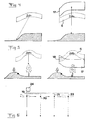
- In the drawings:
- Fig 1
- is a schematic view illustrating an aeroplane flying over a terrain portion and provided with a system for navigation according to the invention in a first stage of a position determination procedure,
- Fig 2
- is a view corresponding to
Fig 1 in a later stage of said procedure, - Fig 3
- is a view corresponding to
Figs 1 and 2 in a still later stage of said procedure, - Figs 4 and 5
- are views similar to the one in
Fig 1 illustrating how different types of terrain may result in measurement faults for a device included in the system according to the invention, - Fig 6
- is a very schematic view illustrating an aspect of the system according to the invention and the method according to the invention, and
- Fig 7
- is a simplified block diagram illustrating the algorithm according to which a device for terrain navigation included in the system according to the invention is adapted to function.
- The construction and the function of the system for navigating an aircraft according to the contour of the terrain overflown thereby according to the invention will now firstly be explained with reference made to
Figs 1-3 in parallel withFig 7 . The aeroplane 1 is provided with aradar altimeter 2 schematically indicated inFig 2 through a measurement cone and adapted to send signals down towards the terrain and analyse signals reflected thereby for measuring the altitude of the terrain just passed. The aeroplane has also a data base with information about altitudes of the terrain within the area in which the aeroplane is present, in which this area could be very large, and the data base could contain information about the contour of the terrain of for example a whole country, such as Sweden, or for the entire earth surface. Terrain information is present in the form of altitude indications for certain fixed points in the terrain, between which the altitude may only be interpolated. - The system also comprises a device 3 for position determination of the aeroplane, the operation algorithm of which is schematically represented in
Fig 7 . This device, which may be called terrain navigating filter, is adapted to operate in the following way: When the aeroplane is located in a position within a given uncertainty area and the position determination procedure is to be started a circle cylindrical measurement shell 4 is formed, which looks like a giant icehockey puck and in which the aeroplane certainly is located. This measurement shell 4 may have a radius of typically 10 km and the vertical thickness thereof may for example be 200 m. Thus, the proportions in the Figures are not correct, but the Figures are only used to explain the invention in a simple way. - We now assume that the
radar altimeter 2 carries out an altitude measurement at a certain time t1, which gives a value of the distance in the vertical direction between the aeroplane and the part of the terrain for which the measurement is carried out, which could be the ground, and the measurement result is then only provided with an error emanating from the measurement method itself, but the measurement may also have been done on for example the top of a tree, and an error depending on the terrain is then introduced, since it has not been measured on the ground. The device comprises means adapted to compare the altitude measured of the terrain with data base information about terrain altitudes within a given uncertainty area and form ameasurement shell 5 extending over this area at the measured distance above the terrain and having a predetermined vertical thickness. For the vertical position of the aeroplane this extends within thelateral limits 6, 7 between a lower limit Sd and an upper limit Su of the measurement shell defined as follows:

- Thus, knowledge is now gained of the fact that the aeroplane is both within the uncertainty area 4 and within the
measurement shell 5, i.e. the section between the uncertainty area 4 and the measurement shell. This means that themeasurement shell 5 is now the new uncertainty area when the aeroplane flies further according toFig 3 . The measurement shell is then moved according to an estimation of the movement of the aeroplane through any moving sensor not shown to the time t2 for the next radar altitude measurement. However, the measurement is influenced by the movement of the aeroplane by a certain uncertainty with respect to the velocity, so that the measurement shell or the uncertainty area has to be expanded somewhat in all directions according to the uncertainty of the velocity. - The uncertainty region moved and somewhat expanded is indicated in
Fig 3 by 8. At this time t2 a new radar altitude measurement is accordingly carried out, which after the comparison described above with data base information results in a new measurement shell 9, and thesection 10 between theuncertainty area 8 and the measurement shell 9 gives anew uncertainty area 10, which shows that the uncertainty of the position of the aeroplane has been reduced drastically. This procedure of time- and measurement updates is continued and the positioning determination gets better gradually. Accordingly, a time update expands the uncertainty area, while an altitude measurement update contracts the uncertainty area, should there be characteristic terrain variations upon which the measurement has taken place. An altitude measurement update will not provide any new information if the ground is flat. Thus, the navigation is very dependent upon variations of the underlying terrain. - For obtaining a high accuracy of the position determination it is necessary to create a small uncertainty area, which may be obtained for example by making the thickness of the measurement shell thinner, but this could then mean that a larger measurement error than the one predicted (N) could occur and then procure an end of the section method, since no section could be formed and thereby a restart of the entire procedure with uncertainty area 4 according to
Fig 1 has to be done. Thus, the choice of N is a compromise between a desire of a small uncertainty area and the risk of getting an empty uncertainty area or section. - The algorithm just described is schematically illustrated in
Fig 7 , in which a box 11 illustrates how it is started with a large uncertainty area, a time update expanding the uncertainty area somewhat takes place inbox 12, whereupon in box 13 a radar altitude measurement takes place, which forms a measurement shell reducing the uncertainty area. It is shown inbox 14 that an attempt is made to form a new section between the measurement shell and the earlier uncertainty area, and if this is succeeded thearrow 15 is followed back to thebox 12 for repeating this procedure between theboxes box 14 is that no section may be formed then thearrow 16 is followed back to the box 11 for restarting the procedure with a large uncertainty area 4 according toFig 1 . - However, in a position determination by a device in the way described above problems may sometimes occur and the device may deliver erroneous values or not have any possibility to deliver values at all during a longer period of time, which is illustrated in
Figs 4 and 5 . - It is shown in
Fig 5 how a "rather" large measurement error, which emanates from the fact that there is a high obstacle on the ground, results in the occurrence of a so called erroneous fixation", since a section between the precedinguncertainty area 5 and thenew one 17 will be formed, but the aeroplane will not be located within thisnew section 18. Is the aeroplane located over flat ground when this takes place the filter will not die, i.e. a restart of the filter will not take place, but the device will continue to deliver erroneous position determinations or estimations during a long period of time. - The present invention is characterized by having on board of an aeroplane at least three devices of the type described above, which are adapted to carry out said procedure for position determination of the aeroplane, and these different devices are indicated by a dashed line 19-22 each in
Fig 6 . Means 24 are arranged for comparing the positions determined by the devices and upon a substantial deviation of any position from the other assume that this is erroneous and form an average of the other positions as the correct position of the aeroplane. The accuracy of the position determination for the navigation may in this way be improved considerably and the risk of faults may be reduced remarkably, since the probability that a plurality of devices give the same erroneous estimation of the position is infinitely low and therefore substantially equal results of the position determinations of different devices mean in the practice that these determinations are correct. The position determinations of the devices should then be made as far as possible independent of each other. This may be achieved for example by arranging said means of each device to form measurement shells of a thickness differing from the measurement shell thicknesses of the means of the other devices, i.e. the expected noise of the altitude measurements may be varied. - Another possibility consists in the fact that the different devices are started with a time delay with respect to each other, so that for example a new device is not started until the latest started device has formed a new section. Such a terrain dependent time delay results in a maintained robustness even over a terrain having small variations.
- Another possibility consists in arranging the radar altimeter to carry out altitude measurements more often than the respective device is adapted to form a new measurement shell, and the respective device is adapted to utilize results from other altitude measurements of the radar altimeter than the other devices. It is already so that the altimeter most often in the practice measures more often than it is necessary to measurement update the devices, so that this possibility is already available and the invention utilizes this possibility. The measurements are then usually carried out at a frequency of 10-30 Hz, preferably about 15 Hz, which for a normal flight speed of an aeroplane means a distance of about 15 m between such measurements at start and landing. The control units of the respective device are then preferably co-ordinated with each other, so that each utilizes the result of altitude measurements of a determined time interval substantially coinciding with corresponding time intervals of control units of other devices, so that for example a device utilizes measurement results from the
measurements 1, 5, 9... in the chronological order, while for another device the corresponding order numbers are 2, 6, 10... - The devices or the filters are advantageously as many as possible, and it is only the capacity of the computer of the aeroplane that sets the limits for how many devices that may be used. At least 5, preferably at least 10 devices are advantageously used in the system.
- It is pointed out that the different devices in the system may in the practice very well be summarized by one single computer program co-operating with the radar altimeter and the data base for performing the algorithm described above for different measurement points associated with the determined imagined device.
- "Radar altimeter" is to be given a broad sense and comprises all types of measurements in which a radar signal is transmitted and reflected by an object or causes a retransmission of any other type of radar signal for analysis and distance calculation.
- The device may as already mentioned be adapted for navigation of other vehicles than aeroplanes according to the contour of the surface region over which they move, such as airborne vehicles or boats. Accordingly, the medium in which the signals of the radar altimeter are transmitted may be air or water. In the case last mentioned it may also be called echo depth sounder.
Claims (19)
- A system for navigating a vehicle according to the contour of a surface region over which it moves, which comprises on-board of the vehicle
a radar altimeter (2) adapted to send signals down towards said surface region and to analyse signals reflected therefrom for measuring the height over the part of the surface region just passed,
a data base with information about the altitude of the surface region within the area in which the vehicle is present and
a device (3, 19-22) having
means (13) adapted to compare the altitude of the surface region last measured with the data base information about surface region altitudes within a given uncertainty area and form a measurement shell (5) extending over this area at the distance measured over the surface region and having a predetermined vertical thickness and having
a control unit adapted
to control this procedure of forming a measurement shell to be repeated for forming new measurement shells and sections (10) between such newly formed shells and the previous measurement shell for determining the position of the vehicle to be within the area of a particular section, and
to control a restart of said procedure if it is failed to form said section between a formed new measurement shell and the previous measurement shell,
the system being characterized in that it comprises
at least three said devices (19-22) adapted to carry out said position determination of the vehicle and
means (24) adapted to compare the positions determined by the devices and upon a substantial deviation of the position from one of the devices from the other devices the other assume that this position is erroneous and form an average of the positions from the other devices as the correct position of the vehicle. - A system according to claim 1, characterized in that the control units of the different devices are adapted to co-operate for reducing the mutual dependency of the position determinations of the devices.
- A system according to claim 2, characterized in that said means (13) of at least one device is adapted to form measurement shells having a thickness differing from the measurement shell thicknesses of the means of at least another device.
- A system according to claim 3, characterized in that said means (13) of each device is adapted to form measurement shells having a thickness differing from the measurement shell thicknesses of the means of the other devices.
- A system according to any of claims 2-4, characterized in that the different devices (19-22) are adapted to start said procedure with a time delay with respect to the other devices.
- A system according to claim 5, characterized in that the different devices (19-22) are adapted to start said procedure with a time delay with respect to each other by not starting the procedure of a net device before the latest started device has formed a said section.
- A system according to any of claims 2-6, characterized in that the radar altimeter (2) is adapted to carry out altitude measurements more often than the respective device (19-22) is adapted to form a new measurement shell, and that the respective device is adapted to utilize results from other altitude measurements of the radar altimeter than the other devices.
- A system according to claim 7, characterized in that the control units of the respective device are co-ordinated with each other to each utilize the result of altitude measurements at a given time interval substantially coinciding with the corresponding time intervals of the control units of other devices.
- A system according to any of the preceding claims, characterized in that the radar altimeter is adapted to carry out the measurements with a frequency of 10-30 Hz, preferably about 15 Hz.
- A system according to any of the preceding claims, characterized in that it comprises at least five, preferably at least ten, such devices.
- A system according to any of the preceding claims, characterized in that it is adapted for navigation of an aircraft, that the radar altimeter (2) is adapted to send signals down towards the terrain just passed by the aircraft for measuring the height of the aircraft over the terrain, and that said data base contains information about altitudes of the terrain within the area in which the aircraft is present.
- A system according to claim 11, characterized in that it is adapted to be arranged on board of said aircraft for navigation thereof according to the contour of the terrain flown over by said aircraft.
- A method for navigating a vehicle according to the contour of a surface region over which it moves, said method comprising the steps of- sending signals through a radar altimeter (2) on board of the vehicle towards a surface region there under- analysing signals reflected by the surface for measuring the altitude of the surface region,- comparing the measured surface region altitude with information about surface region altitudes within a given area, said information being stored in a database,- forming a measurement shell (5) extending over this area at the measured distance above the surface region and having a predetermined vertical thickness,- repeatedly forming a new measurement shell in accordance with the foregoing steps and for each formed new measurement shell forming sections (10) between a new measurement shell and the previous measurement shell for determination of the position to be within the area of a particular section,
said procedure being restarted if no section could be formed, characterized by the steps of
carrying out the position determination of the vehicle through at least three different devices (19-22),
comparing the positions determined by the different devices, and
when the comparison indicates a substantial deviation of the position determined by one of the devices from the positions determined by the other devices, it is assumed that this position is erroneous, and an average of the positions from the other devices is formed as the correct position of the vehicle. - A method according to claim 13, characterized in that the different devices (19-22) are brought to co-operate so that the mutual dependency of the position determinations of the devices is reduced.
- A method according to claim 14, characterized in that for at least one device measurement shells having a thickness differing from the measurement shell thicknesses of at least another device are formed for reducing said dependency.
- A method according to claim 14 or 15, characterized in that said procedure of one of the devices (19-22) is started with a time delay with respect to the other devices.
- A method according to any of claims 14-16, characterized in that altitude measurements are carried out through the radar altimeter (2) more often than the respective device forms a new measurement shell, and that the respective device is brought to utilize results from other altitude measurements of the radar altimeter (2) than the other devices.
- A method according to any of claims 13-17, characterized in that for navigating an aircraft according to the contour of the terrain flown over, by said aircraft, signals are sent through the radar altimeter (2) on board of the aircraft towards the terrain just passed by the aircraft for measuring the height of the aircraft thereabove, and that the measured altitude of the terrain is compared with data base information about altitudes of the terrain within the area in which the aircraft is present.
- A method according to claim 18, characterized in that it is used for navigating said aircraft according to the contour of the terrain flown over by said aircraft.
Applications Claiming Priority (3)
| Application Number | Priority Date | Filing Date | Title |
|---|---|---|---|
| SE0000451A SE515860C2 (en) | 2000-02-14 | 2000-02-14 | Installation and procedure for navigating a vehicle |
| SE0000451 | 2000-02-14 | ||
| PCT/SE2001/000211 WO2001059407A1 (en) | 2000-02-14 | 2001-02-06 | A plant and a method for navigating a vehicle |
Publications (2)
| Publication Number | Publication Date |
|---|---|
| EP1259777A1 EP1259777A1 (en) | 2002-11-27 |
| EP1259777B1 true EP1259777B1 (en) | 2009-08-12 |
Family
ID=32710027
Family Applications (1)
| Application Number | Title | Priority Date | Filing Date |
|---|---|---|---|
| EP01904705A Expired - Lifetime EP1259777B1 (en) | 2000-02-14 | 2001-02-06 | A system and a method for navigating a vehicle |
Country Status (8)
| Country | Link |
|---|---|
| US (1) | US6725153B2 (en) |
| EP (1) | EP1259777B1 (en) |
| AT (1) | ATE439571T1 (en) |
| AU (1) | AU774969B2 (en) |
| DE (1) | DE60139546D1 (en) |
| ES (1) | ES2328557T3 (en) |
| SE (1) | SE515860C2 (en) |
| WO (1) | WO2001059407A1 (en) |
Families Citing this family (7)
| Publication number | Priority date | Publication date | Assignee | Title |
|---|---|---|---|---|
| US7095364B1 (en) * | 2005-08-04 | 2006-08-22 | The Boeing Company | Altitude measurement system and associated methods |
| US7831369B2 (en) * | 2005-11-16 | 2010-11-09 | Gm Global Technology Operations, Inc. | Method and apparatus for vehicle and engine operation |
| DE102006007006A1 (en) * | 2006-02-15 | 2007-08-16 | Eads Deutschland Gmbh | Method for database-supported estimation of an output variable in a k-dimensional value range |
| US8604970B1 (en) * | 2010-06-04 | 2013-12-10 | Rockwell Collins, Inc. | Systems and methods for generating data in a digital radio altimeter and detecting transient radio altitude information |
| CN106382933B (en) * | 2016-11-04 | 2019-09-10 | 北京农业智能装备技术研究中心 | A kind of operation course line acquisition methods and system for aviation plant protection aircraft |
| JP7196653B2 (en) * | 2019-02-05 | 2022-12-27 | トヨタ自動車株式会社 | Information processing system, program, and information processing method |
| US10852158B1 (en) * | 2019-09-27 | 2020-12-01 | Kitty Hawk Corporation | Distance sensor test system |
Citations (1)
| Publication number | Priority date | Publication date | Assignee | Title |
|---|---|---|---|---|
| US5331562A (en) * | 1992-01-16 | 1994-07-19 | Honeywell Inc. | Terrain referenced navigation-adaptive filter distribution |
Family Cites Families (10)
| Publication number | Priority date | Publication date | Assignee | Title |
|---|---|---|---|---|
| US3213451A (en) * | 1963-03-29 | 1965-10-19 | Frederick C Alpers | Airborne contour-sensing radar |
| US6218980B1 (en) * | 1982-09-13 | 2001-04-17 | Mcdonnell Douglas Corporation | Terrain correlation system |
| US4567483A (en) * | 1982-12-10 | 1986-01-28 | Sundstrand Data Control, Inc. | Position based ground proximity warning system for aircraft |
| US4646244A (en) * | 1984-02-02 | 1987-02-24 | Sundstrand Data Control, Inc. | Terrain advisory system |
| US4649389A (en) * | 1984-03-27 | 1987-03-10 | Westinghouse Electric Corp. | Stacked beam radar and target height measurement extractor especially for use therein |
| DE3427020A1 (en) * | 1984-07-21 | 1986-01-23 | Messerschmitt-Bölkow-Blohm GmbH, 8012 Ottobrunn | NAVIGATION AND FLIGHT GUIDANCE |
| US4698635A (en) * | 1986-03-02 | 1987-10-06 | The United States Of America As Represented By The Secretary Of The Navy | Radar guidance system |
| EP0267346B1 (en) * | 1986-11-12 | 1991-01-16 | LITEF GmbH | Method of determining the altitude of an aircraft |
| EP0311312A3 (en) * | 1987-10-07 | 1990-12-12 | Smiths Industries Public Limited Company | Radar altimeter systems |
| US5047779A (en) * | 1990-08-28 | 1991-09-10 | Honeywell Inc. | Aircraft radar altimeter with multiple target tracking capability |
-
2000
- 2000-02-14 SE SE0000451A patent/SE515860C2/en not_active IP Right Cessation
-
2001
- 2001-02-06 WO PCT/SE2001/000211 patent/WO2001059407A1/en not_active Ceased
- 2001-02-06 AU AU32533/01A patent/AU774969B2/en not_active Expired
- 2001-02-06 ES ES01904705T patent/ES2328557T3/en not_active Expired - Lifetime
- 2001-02-06 DE DE60139546T patent/DE60139546D1/en not_active Expired - Lifetime
- 2001-02-06 AT AT01904705T patent/ATE439571T1/en not_active IP Right Cessation
- 2001-02-06 EP EP01904705A patent/EP1259777B1/en not_active Expired - Lifetime
-
2002
- 2002-06-26 US US10/180,381 patent/US6725153B2/en not_active Expired - Lifetime
Patent Citations (1)
| Publication number | Priority date | Publication date | Assignee | Title |
|---|---|---|---|---|
| US5331562A (en) * | 1992-01-16 | 1994-07-19 | Honeywell Inc. | Terrain referenced navigation-adaptive filter distribution |
Also Published As
| Publication number | Publication date |
|---|---|
| SE0000451L (en) | 2001-08-15 |
| WO2001059407A1 (en) | 2001-08-16 |
| ATE439571T1 (en) | 2009-08-15 |
| US6725153B2 (en) | 2004-04-20 |
| EP1259777A1 (en) | 2002-11-27 |
| ES2328557T3 (en) | 2009-11-16 |
| SE515860C2 (en) | 2001-10-22 |
| SE0000451D0 (en) | 2000-02-14 |
| AU774969B2 (en) | 2004-07-15 |
| US20040002811A1 (en) | 2004-01-01 |
| AU3253301A (en) | 2001-08-20 |
| DE60139546D1 (en) | 2009-09-24 |
Similar Documents
| Publication | Publication Date | Title |
|---|---|---|
| EP1317677B1 (en) | Method and system for high precision altitude measurement over hostile terrain | |
| US6865477B2 (en) | High resolution autonomous precision positioning system | |
| US5654890A (en) | High resolution autonomous precision approach and landing system | |
| CA1111953A (en) | Vehicle guidance system | |
| EP0649034B1 (en) | SAR/GPS inertial method of range measurement | |
| CN111221018B (en) | A GNSS multi-source information fusion navigation method for suppressing maritime multipath | |
| US6744401B2 (en) | Methods and apparatus for radar data processing | |
| US11029159B2 (en) | Navigation system | |
| US6803878B2 (en) | Methods and apparatus for terrain correlation | |
| JP6567665B2 (en) | A method for estimating each drift (floating) vector at all points in a ship's route | |
| US5331562A (en) | Terrain referenced navigation-adaptive filter distribution | |
| US6725153B2 (en) | System and a method for navigating a vehicle | |
| JP3962403B2 (en) | Advanced computing device and method | |
| Campbell et al. | Terrain‐Referenced Positioning Using Airborne Laser Scanner | |
| CN116710909B (en) | Electronic device for storing a topographic database, method for generating such a database, avionics system, monitoring method and related computer program | |
| EP3988900B1 (en) | Terrain referenced navigation system | |
| US20240331554A1 (en) | Method and system for generating and providing descriptors of meteorological obstacles | |
| EP1325352B1 (en) | Adaptive measurement correction during remote distance measurement | |
| Pucar et al. | Saab NINS/NILS-an autonomons landing system for Gripen | |
| Brozena et al. | East coast gravity validation study | |
| JP2021023224A (en) | Growth value calculation method and growth value calculation system |
Legal Events
| Date | Code | Title | Description |
|---|---|---|---|
| PUAI | Public reference made under article 153(3) epc to a published international application that has entered the european phase |
Free format text: ORIGINAL CODE: 0009012 |
|
| 17P | Request for examination filed |
Effective date: 20020618 |
|
| AK | Designated contracting states |
Kind code of ref document: A1 Designated state(s): AT BE CH CY DE DK ES FI FR GB GR IE IT LI LU MC NL PT SE TR |
|
| AX | Request for extension of the european patent |
Free format text: AL;LT;LV;MK;RO;SI |
|
| RIN1 | Information on inventor provided before grant (corrected) |
Inventor name: PERSSON, NIKLAS |
|
| 17Q | First examination report despatched |
Effective date: 20070509 |
|
| GRAP | Despatch of communication of intention to grant a patent |
Free format text: ORIGINAL CODE: EPIDOSNIGR1 |
|
| RTI1 | Title (correction) |
Free format text: A SYSTEM AND A METHOD FOR NAVIGATING A VEHICLE |
|
| GRAS | Grant fee paid |
Free format text: ORIGINAL CODE: EPIDOSNIGR3 |
|
| GRAA | (expected) grant |
Free format text: ORIGINAL CODE: 0009210 |
|
| AK | Designated contracting states |
Kind code of ref document: B1 Designated state(s): AT BE CH CY DE DK ES FI FR GB GR IE IT LI LU MC NL PT SE TR |
|
| REG | Reference to a national code |
Ref country code: GB Ref legal event code: FG4D |
|
| REG | Reference to a national code |
Ref country code: CH Ref legal event code: EP |
|
| REG | Reference to a national code |
Ref country code: IE Ref legal event code: FG4D |
|
| REF | Corresponds to: |
Ref document number: 60139546 Country of ref document: DE Date of ref document: 20090924 Kind code of ref document: P |
|
| REG | Reference to a national code |
Ref country code: ES Ref legal event code: FG2A Ref document number: 2328557 Country of ref document: ES Kind code of ref document: T3 |
|
| PG25 | Lapsed in a contracting state [announced via postgrant information from national office to epo] |
Ref country code: FI Free format text: LAPSE BECAUSE OF FAILURE TO SUBMIT A TRANSLATION OF THE DESCRIPTION OR TO PAY THE FEE WITHIN THE PRESCRIBED TIME-LIMIT Effective date: 20090812 Ref country code: SE Free format text: LAPSE BECAUSE OF FAILURE TO SUBMIT A TRANSLATION OF THE DESCRIPTION OR TO PAY THE FEE WITHIN THE PRESCRIBED TIME-LIMIT Effective date: 20090812 Ref country code: AT Free format text: LAPSE BECAUSE OF FAILURE TO SUBMIT A TRANSLATION OF THE DESCRIPTION OR TO PAY THE FEE WITHIN THE PRESCRIBED TIME-LIMIT Effective date: 20090812 |
|
| NLV1 | Nl: lapsed or annulled due to failure to fulfill the requirements of art. 29p and 29m of the patents act | ||
| PG25 | Lapsed in a contracting state [announced via postgrant information from national office to epo] |
Ref country code: NL Free format text: LAPSE BECAUSE OF FAILURE TO SUBMIT A TRANSLATION OF THE DESCRIPTION OR TO PAY THE FEE WITHIN THE PRESCRIBED TIME-LIMIT Effective date: 20090812 |
|
| PG25 | Lapsed in a contracting state [announced via postgrant information from national office to epo] |
Ref country code: PT Free format text: LAPSE BECAUSE OF FAILURE TO SUBMIT A TRANSLATION OF THE DESCRIPTION OR TO PAY THE FEE WITHIN THE PRESCRIBED TIME-LIMIT Effective date: 20091212 |
|
| PG25 | Lapsed in a contracting state [announced via postgrant information from national office to epo] |
Ref country code: DK Free format text: LAPSE BECAUSE OF FAILURE TO SUBMIT A TRANSLATION OF THE DESCRIPTION OR TO PAY THE FEE WITHIN THE PRESCRIBED TIME-LIMIT Effective date: 20090812 |
|
| PLBE | No opposition filed within time limit |
Free format text: ORIGINAL CODE: 0009261 |
|
| STAA | Information on the status of an ep patent application or granted ep patent |
Free format text: STATUS: NO OPPOSITION FILED WITHIN TIME LIMIT |
|
| PG25 | Lapsed in a contracting state [announced via postgrant information from national office to epo] |
Ref country code: BE Free format text: LAPSE BECAUSE OF FAILURE TO SUBMIT A TRANSLATION OF THE DESCRIPTION OR TO PAY THE FEE WITHIN THE PRESCRIBED TIME-LIMIT Effective date: 20090812 |
|
| 26N | No opposition filed |
Effective date: 20100517 |
|
| REG | Reference to a national code |
Ref country code: CH Ref legal event code: PL |
|
| PG25 | Lapsed in a contracting state [announced via postgrant information from national office to epo] |
Ref country code: GR Free format text: LAPSE BECAUSE OF FAILURE TO SUBMIT A TRANSLATION OF THE DESCRIPTION OR TO PAY THE FEE WITHIN THE PRESCRIBED TIME-LIMIT Effective date: 20091113 Ref country code: CH Free format text: LAPSE BECAUSE OF NON-PAYMENT OF DUE FEES Effective date: 20100228 Ref country code: MC Free format text: LAPSE BECAUSE OF NON-PAYMENT OF DUE FEES Effective date: 20100301 Ref country code: LI Free format text: LAPSE BECAUSE OF NON-PAYMENT OF DUE FEES Effective date: 20100228 |
|
| PG25 | Lapsed in a contracting state [announced via postgrant information from national office to epo] |
Ref country code: IE Free format text: LAPSE BECAUSE OF NON-PAYMENT OF DUE FEES Effective date: 20100206 |
|
| PG25 | Lapsed in a contracting state [announced via postgrant information from national office to epo] |
Ref country code: CY Free format text: LAPSE BECAUSE OF FAILURE TO SUBMIT A TRANSLATION OF THE DESCRIPTION OR TO PAY THE FEE WITHIN THE PRESCRIBED TIME-LIMIT Effective date: 20090812 |
|
| PG25 | Lapsed in a contracting state [announced via postgrant information from national office to epo] |
Ref country code: LU Free format text: LAPSE BECAUSE OF NON-PAYMENT OF DUE FEES Effective date: 20100206 |
|
| PG25 | Lapsed in a contracting state [announced via postgrant information from national office to epo] |
Ref country code: TR Free format text: LAPSE BECAUSE OF FAILURE TO SUBMIT A TRANSLATION OF THE DESCRIPTION OR TO PAY THE FEE WITHIN THE PRESCRIBED TIME-LIMIT Effective date: 20090812 |
|
| REG | Reference to a national code |
Ref country code: FR Ref legal event code: PLFP Year of fee payment: 16 |
|
| REG | Reference to a national code |
Ref country code: FR Ref legal event code: PLFP Year of fee payment: 17 |
|
| REG | Reference to a national code |
Ref country code: FR Ref legal event code: PLFP Year of fee payment: 18 |
|
| PGFP | Annual fee paid to national office [announced via postgrant information from national office to epo] |
Ref country code: GB Payment date: 20200218 Year of fee payment: 20 Ref country code: DE Payment date: 20200220 Year of fee payment: 20 Ref country code: IT Payment date: 20200219 Year of fee payment: 20 Ref country code: ES Payment date: 20200302 Year of fee payment: 20 |
|
| PGFP | Annual fee paid to national office [announced via postgrant information from national office to epo] |
Ref country code: FR Payment date: 20200217 Year of fee payment: 20 |
|
| REG | Reference to a national code |
Ref country code: DE Ref legal event code: R071 Ref document number: 60139546 Country of ref document: DE |
|
| REG | Reference to a national code |
Ref country code: GB Ref legal event code: PE20 Expiry date: 20210205 |
|
| PG25 | Lapsed in a contracting state [announced via postgrant information from national office to epo] |
Ref country code: GB Free format text: LAPSE BECAUSE OF EXPIRATION OF PROTECTION Effective date: 20210205 |
|
| REG | Reference to a national code |
Ref country code: ES Ref legal event code: FD2A Effective date: 20211229 |
|
| PG25 | Lapsed in a contracting state [announced via postgrant information from national office to epo] |
Ref country code: ES Free format text: LAPSE BECAUSE OF EXPIRATION OF PROTECTION Effective date: 20210207 |